Tagsys L200TUNANT500 RFID PASSIVE TAG READER User Manual Conveyor Tunnel Reader V1 0
Tagsys S.A. RFID PASSIVE TAG READER Conveyor Tunnel Reader V1 0
Tagsys >
USERS MANUAL

50x50 CONVEYOR TUNNEL READER
User's Guide
Revision 1.0
November 2007

CONVEYOR TUNNEL READER User's Guide
2/45 Revision 1.0 November 2007
Publishing Information
Disclaimer and Limitation of Liability
All information herein is either public information or is the property of and owned solely by TAGSYS who shall have and
keep the sole right to file patent applications or any other kind of intellectual property protection in connection with such
information.
Nothing herein shall be construed as implying or granting to you any rights, by license, grant or otherwise, under any
intellectual and/or industrial property rights of or concerning any of TAGSYS’ information.
This document can be used for informational, non-commercial, internal and personal use only provided that:
the copyright notice below, the confidentiality and proprietary legend and this full warning notice appear in all copies.
this document shall not be posted on any network computer or broadcast in any media and no modification of any
part of this document shall be made.
Use for any other purpose is expressly prohibited and may result in severe civil and criminal liabilities.
The information contained in this document is provided “AS IS” without any warranty of any kind. Unless otherwise
expressly agreed in writing, TAGSYS makes no warranty as to the value or accuracy of information contained herein.
The document could include technical inaccuracies or typographical errors. Changes are periodically added to the
information herein. Furthermore, TAGSYS reserves the right to make any change or improvement in the specifications
data, information, and the like described herein, at any time.
Therefore TAGSYS assumes no liability and is not responsible for customer applications or product or software that
include TAGSYS products.
TAGSYS HEREBY DISCLAIMS ALL WARRANTIES AND CONDITIONS WITH REGARD TO THE INFORMATION
CONTAINED HEREIN, INCLUDING ALL IMPLIED WARRANTIES OF MERCHANTABILITY, FITNESS FOR A
PARTICULAR PURPOSE, TITLE AND NON-INFRINGEMENT. IN NO EVENT SHALL TAGSYS BE LIABLE, WHETHER
IN CONTRACT, TORT OR OTHERWISE, FOR ANY INDIRECT, SPECIAL OR CONSEQUENTIAL DAMAGES OR ANY
DAMAGES WHATSOEVER INCLUDING BUT NOT LIMITED TO DAMAGES RESULTING FROM LOSS OF USE,
DATA, PROFITS, REVENUES, OR CUSTOMERS, ARISING OUT OF OR IN CONNECTION WITH THE USE OR
PERFORMANCE OF INFORMATION CONTAINED IN THIS DOCUMENT.
TAGSYS does not and shall not warrant that this product/system/equipment will be resistant to all possible attacks, and
shall not incur, and disclaims, any liability in this respect. Even if each product is compliant with current security
standards in force on the date of their design, security mechanisms' resistance necessarily evolves according to the
state-of-the-art in security and notably under the emergence of new attacks. Under no circumstances shall TAGSYS be
held liable for any third party actions, and in particular in case of any successful attack against systems or equipment
incorporating TAGSYS products.
TAGSYS disclaims any liability with respect to security for direct, indirect, incidental or consequential damages that result
from any use of its products. It is further stressed that independent testing and verification by the person using the
product is particularly encouraged, especially in any application in which defective, incorrect, or insecure functioning
could result in damage to persons or property, denial of service, or loss of privacy.
© 2000-2007 TAGSYS. All rights reserved.
TRADEMARKS. TAGSYS is a registered trademark of TAGSYS S.A, all rights reserved. ARIO, FOLIO and other
TAGSYS products referenced in these pages are either trademarks or registered trademarks of TAGSYS S.A. Other
products and company names mentioned in these pages may be the trademarks of their respective owners.
Microsoft, Visual C++, Windows, and Windows NT are either registered trademarks or trademarks of Microsoft
Corporation in the U.S.A. and/or other countries.
I-Code is a registered trademark of Philips.
Tag-It is a registered trademark of Texas Instruments.
Printed in France.
TAGSYS – 180 Chemin de St Lambert, 13821 LA PENNE SUR HUVEAUNE, France.
Tel: +33 (0) 4.91.27.57.00 / fax: +33 (0) 4.91.27.57.01
Document Reference: DOC12454A0
Read This First
November 2007 Revision 1.0 3/45
Read This First
Welcome to the TAGSYS RFID System. This User's Guide is designed to help you get up and
running quickly using this high-quality Radio Frequency Identification (RFID) system. It describes
all you need to know about how to install and use the TAGSYS system and its associated
applications.
It provides a step-by-step guide for the following procedures:
Installation of the CONVEYOR TUNNEL READER
Select the best-adapted configuration for your application (Standalone Mode)
Troubleshoot any eventual problems.
After you become familiar with the basic functions of the product, you can use the rest of this
handbook as a reference for less common tasks, for maintaining your system, and also as a
source of information if you have problems operating the system.
This End User’s Guide is designed for all CIT (Certified Integrators by TAGSYS) and for TAGSYS
Expert Network customers implementing a low-cost and high-performance RFID solution.
This document does not assume any previous knowledge of Radio Frequency Identification (RFID)
technology.
Conventions
Symbol Meaning
CAUTION: A note that advises users that a specific action could result in the loss of data or
damage the hardware.
WARNING: A note that advises users that a specific action may result in physical harm.
A note that provides additional information that helps the user perform a task or obtain the
best performance from the product.
Abbreviations and Acronyms
ASK Amplitude Shift Keying
CPU Central Processing Unit
CRC Cyclic Redundancy Check
DLL Dynamic-Link Library
DSP Digital Signal Processor
ETX End of Text
HPI Host Port Interface
I/O Input/Output
LED Light Emitting Diode
LSB Least Significant Bit

CONVEYOR TUNNEL READER User's Guide
4/45 Revision 1.0 November 2007
MSB Most Significant Bit
OS Operating System
PC Personal Computer
PCB Printed Circuit Board
PLC Programmable Logic Controller
RAM Random Access Memory
RF Radio Frequency
RFID Radio Frequency Identification
RFU Reserved for Future Use
RTF Reader Talks First
TTF Tag Talks First
TTL Transistor-Transistor Logic
TTY TeleTYpe
Glossary
Anti-Collision Tag capability making it readable while other tags are present in the RF field.
Antenna An aerial that receives and/or transmits radio frequency signals. Aerials are
manufactured in a variety of forms, shapes and sizes.
Baud A unit of measure of data transmission speed representing the number of signal changes per
second.
BNC Connector Cylindrical metal connector with a copper core that is located at the tip of a
coaxial cable, and is used to connect cables together. It attaches by pushing and twisting the outer
cylinder on to two locking pins.
Digital Signal Processor This part of the Radio Processing Unit (RPU) performs real-time smart
label decoding and manages the Medio L200 configuration.
Dynamic-Link Library Executable routines that are stored as separate files with DLL extensions
and executed only when needed by the program.
Host Port Interface Interface used to access the DSP memory.
Monitoring Port Parallel Port granting access to the HPI. It communicates directly with the Radio
Processing Unit
Multi-Read See Anti-Collision
Packaged Reader A reader in its casing.
Phase Shift Difference of phase between the 13.56 MHz field emitted by two antennas. This
feature is dedicated to rotating field applications and three-dimensional volume smart label
detection.
PLC Programmable Logic Controller
Protocol A set of rules governing a particular function, such as the flow of data/information in a
communication system (communication between a smart label and a reader or a reader and a PC
or host computer).
Radio Frequency Identification System (RFID) An automatic identification and data capture
system comprising one or more readers and one or more smart labels in which data transfer is
achieved by means of suitable modulated inductive or radiating electromagnetic carriers.

Read This First
November 2007 Revision 1.0 5/45
Radio Processing Unit This unit controls the main features of TAGSYS Lx00 reader units, such
as the RF channels, the multiplexer and the smart label decoding.
Reader Electronic system for the communication between smart labels and host computers.
Reader Talks First Chip protocol for exchanges between the reader and the chip, whereby the
chip waits for a command from the reader to which it responds.
RS-232 Electronic Industries Association (EIA) standard for serial interfaces between computers
and peripherals that defines the function, the electrical characteristics and the timing of signals.
RS-485 Electronic Industries Association (EIA) standard for multipoint, differential data
transmission. It allows multiple nodes to communicate bi-directionally over 1 or 2 twisted pairs.
Smart Label Small, flexible tag from the 13.56 MHz TAGSYS product line. A smart label is made
of a chip connected to an etched antenna.
Tag See Smart Label.
Tag Talks First Chip protocol for exchanges between the reader and the chip, whereby the tag
sends information continuously, without waiting for a specific command from the reader.
Transceiver A combined transmitter and receiver.
Transponder A combined receiver/transmitter that automatically transmits a signal when a ‘trigger’
is received by it. The trigger is often a pulse, called an interrogation pulse.

CONVEYOR TUNNEL READER User's Guide
6/45 Revision 1.0 November 2007
If you need assistance
Please contact your nearest TAGSYS sales representative or the TAGSYS welcome desk at:
Telephone: +33 (0) 4 91 27 57 00
Fax: +33 (0) 4 91 27 57 01
E-Mail: tagsys@tagsysrfid.com
Website: http://www.tagsysrfid.com
Contact for Comments
We welcome your feedback to help us provide high quality documentation.
For technical comments, please contact our welcome desk:
Telephone: +33 (0) 4 91 27 57 00
Fax: +33 (0) 4 91 27 57 01
E-Mail: tagsys@tagsysrfid.com
Please remember to quote the Document Reference Number DOC12454A0, your job title and your
company.
Quality Issues
TAGSYS implements stringent quality controls at all stages of its manufacturing process. However,
should you find a defect with this product, please notify your TAGSYS Quality Service
representative using the dedicated Product Return Form.
Telephone: +33 (0) 4 91 27 57 36
Fax: +33 (0) 4 91 27 57 02
Read This First
November 2007 Revision 1.0 7/45
Table of Contents
PUBLISHING INFORMATION __________________________________________________________ 2
DISCLAIMER AND LIMITATION OF LIABILITY__________________________________________________ 2
READ THIS FIRST ____________________________________________________________________ 3
CONVENTIONS _________________________________________________________________________ 3
ABBREVIATIONS AND ACRONYMS _________________________________________________________ 3
GLOSSARY ____________________________________________________________________________ 4
IF YOU NEED ASSISTANCE________________________________________________________________ 6
CONTACT FOR COMMENTS _______________________________________________________________ 6
QUALITY ISSUES _______________________________________________________________________ 6
1 FOR YOUR SAFETY _______________________________________________________________ 9
1.1 GENERAL USE ____________________________________________________________________ 9
1.2 CARE AND MAINTENANCE ___________________________________________________________ 9
1.3 IMPORTANT SAFETY INFORMATION____________________________________________________ 9
1.3.1 OPERATING ENVIRONMENT ________________________________________________________ 9
2 CERTIFICATION__________________________________________________________________ 11
2.1 OCCUPATIONAL HEALTH AND SAFETY NOTICES________________________________________ 11
2.2 REGULATORY NOTICES ____________________________________________________________ 11
2.2.1 IN EUROPE (CE AND RTTE DIRECTIVES)____________________________________________ 11
2.2.2 IN USA (FCC DIRECTIVE)_________________________________________________________ 12
2.2.3 IN CANADA _____________________________________________________________________ 13
3 SYSTEM OVERVIEW______________________________________________________________ 14
3.1 FEATURES_______________________________________________________________________ 14
3.2 BRIEF CONVEYOR TUNNEL READER DESCRIPTION______________________________________ 15
4 MODES OF OPERATION __________________________________________________________ 17
4.1 CONVEYOR TUNNEL STANDALONE MODE _____________________________________________ 17
4.1.1 RS232 SERIAL COMMUNICATION PARAMETERS_______________________________________ 17
4.1.2 ADDITIONAL FEATURES TO STANDALONE MODE FRAME FORMAT_________________________ 18
4.2 CONVEYOR TUNNEL SLAVE MODE ___________________________________________________ 20
4.2.1 CONVEYOR COMMANDS (FOR SLAVE MODE WITH EXTERNAL CONVEYOR COMMAND)_________ 22
4.3 TAG COMPLIANCE ________________________________________________________________ 23
4.4 ARCHITECTURE OF THE INCLUDED LONG RANGE READER _______________________________ 24
4.5 TAGSYS CONVEYOR TUNNEL READER CONNECTIONS__________________________________ 24
4.5.1 SERIAL CONNECTOR _____________________________________________________________ 24
4.5.2 MONITORING PORT (PARALLEL PORT)______________________________________________ 25
4.5.3 ETHERNET PORT ON THE PLC CONTROLLER _________________________________________ 25
4.5.4 MAIN POWER SUPPLY ____________________________________________________________ 25

CONVEYOR TUNNEL READER User's Guide
8/45 Revision 1.0 November 2007
5 INSTALLATION __________________________________________________________________ 26
5.1 CONVEYOR TUNNEL READER _______________________________________________________ 26
5.1.1 INSTALLING ____________________________________________________________________ 26
6 OPERATION _____________________________________________________________________ 27
6.1 STARTING THE SYSTEM ____________________________________________________________ 27
6.2 NORMAL OPERATION______________________________________________________________ 27
6.3 SHUTDOWN______________________________________________________________________ 27
7 USING THE L200 EXPLORER______________________________________________________ 28
7.1 READER INFORMATION ____________________________________________________________ 29
7.2 GENERAL READER SETTINGS _______________________________________________________ 29
7.3 DEBUGGING TOOLS _______________________________________________________________ 30
7.3.1 DEBUG DIALOG BOX _____________________________________________________________ 30
7.4 STANDALONE MODE CONFIGURATION ________________________________________________ 31
8 L200 READER CONFIGURATION __________________________________________________ 32
8.1 L200 READER SLAVE MODE CONFIGURATION _________________________________________ 32
8.2 L200 READER STANDALONE MODE CONFIGURATION ___________________________________ 32
8.2.1 GENERAL PARAMETERS __________________________________________________________ 32
8.2.2 CHANNEL PARAMETERS __________________________________________________________ 32
8.2.3 TAG MESSAGE FRAME FORMAT ____________________________________________________ 33
8.2.4 SORTING PARAMETERS __________________________________________________________ 33
8.2.5 TRIGGER PARAMETERS __________________________________________________________ 33
8.2.6 WATCHDOG ____________________________________________________________________ 34
8.2.7 TYPICAL STANDALONE MODE PARAMETERS FOR 370DL LAUNDRY TAG READING ___________ 35
9 TECHNICAL SPECIFICATIONS ____________________________________________________ 36
9.1 TECHNICAL SPECIFICATIONS________________________________________________________ 36
9.1.1 SERIAL PORT PIN ASSIGNMENT ____________________________________________________ 36
10 WARRANTY CONDITIONS _______________________________________________________ 43
10.1 WARRANTY EXCLUSIONS _________________________________________________________ 43
10.2 GENERAL PROVISIONS ___________________________________________________________ 43
10.3 HOW TO RETURN DEFECTIVE PRODUCTS ____________________________________________ 44

For Your Safety
November 2007 Revision 1.0 9/45
1 For Your Safety
1.1 General Use
The CONVEYOR TUNNEL READER is designed to be rugged and reliable and to provide years of
trouble-free service. Please observe the following general tips:
Take care not to scratch the device. Keep the device clean. When working with the device,
use only TAGSYS-approved accessories.
This device is not waterproof and should not be exposed to rain or moisture. Under extreme
conditions, water may enter the circuitry.
Take care not to drop the device or subject it to any strong impact.
Protect the device from extreme temperatures. For example, do not leave the device in
front of a window on a hot day, and keep it away from heaters and other heat sources.
Do not store or use the device in any location that is extremely dusty, damp, or wet.
Use a soft, damp cloth to clean the device. If the surface of the device becomes soiled,
clean it with a soft cloth moistened with a diluted window-cleaning solution.
1.2 Care and Maintenance
This device is a product of superior design and should be handled with care. The suggestions
below will further increase the lifetime of this device.
Keep the device and all parts and accessories out of the reach of small children.
Keep the device dry. Precipitation, humidity and liquids contain minerals that will corrode
electronic circuits.
Do not use or store the device in dusty, dirty areas. Its moving parts can be damaged.
Do not store in hot areas. High temperatures can shorten the life of electronic devices,
damage batteries and warp or melt certain plastics.
Do not store in cold areas. When the device warms up (to its normal temperature), moisture
can form inside the device, which may damage electronic circuit boards.
Do not attempt to open the device. Non-professional handling of the device may damage it.
Handle the device with care. Shocks may break internal circuit boards.
Do not clean the device with harsh chemicals, cleaning solvents or strong detergents.
Gently wipe the device with a soft cloth slightly dampened in a mild soap-and-water
solution.
Do not paint the device. Paint may clog the device’s moving parts and prevent proper
operation. Paint with metallic contents may limit device performance.
1.3 Important Safety Information
1.3.1 Operating Environment
Follow all special regulations that are applicable in any area and always switch off the device
whenever its use is prohibited, or when it may cause interference or danger.

CONVEYOR TUNNEL READER User's Guide
10/45 Revision 1.0 November 2007
When connecting the device or any accessory to another device, read its user’s guide for detailed
safety instructions. Do not connect incompatible products.
As with all RF equipment, users are advised that the equipment should only be used in its normal
operating position.
Certification
November 2007 Revision 1.0 11/45
2 Certification
At the moment UL certification is in progress for this product.
2.1 Occupational Health and Safety Notices
TAGSYS CONVEYOR TUNNEL READER has been designed and tested to be in conformity with
the limits given in the European Standard EN 50364 “Limitation of human exposure to
electromagnetic fields from devices used in Electronic Article Surveillance (EAS), Radio Frequency
Identification (RFID) and similar applications” in conjunction with the European Standard EN 50357
describing how to evaluate the exposure level.
CAUTION: Modification of any TAGSYS System is prohibited without the written consent of
TAGSYS. Unauthorized modifications may void the conformity of the equipment to safety
standards and will void the TAGSYS warranty.
2.2 Regulatory Notices
An RFID system typically composed of an RF emission device such as the CONVEYOR TUNNEL
READER is subject to national regulations that may differ by country.
One important item to consider is the maximum permissible magnetic field intensity at a distance of
10 meters from the antenna that must not exceed 42 dBµA/m in Europe and 38 dBµA/m in US.
The CONVEYOR TUNNEL READER meets these limits.
2.2.1 In Europe (CE and RTTE Directives)
The CONVEYOR TUNNEL READER complies (CE Declaration of Conformity granted) with the
European EMC directive.
The CONVEYOR TUNNEL READER complies with the requirements of the Telecommunication
Terminal Equipment Act (FTEG) and the RTTE Directive 1995/5/EC.
It is the responsibility of the CIT (Certified Integrators by TAGSYS) to install the CONVEYOR
TUNNEL READER as described in this User’s Guide or in TAGSYS Documentation.
If a CONVEYOR TUNNEL READER is further integrated in a different product, it is the
responsibility of the manufacturer of this complementary product to obtain the required
approvals for this product.
CONVEYOR TUNNEL READER User's Guide
12/45 Revision 1.0 November 2007
2.2.2 In USA (FCC Directive)
CONVEYOR TUNNEL READER
WARNING TO USERS IN THE UNITED STATES
FEDERAL COMMUNICATIONS COMMISSION (FCC) RADIO
INTERFERENCE STATEMENT 47 CFR Section 15.105(b)
This equipment has been tested and been found to comply with the limits for a Class B digital
device, pursuant to Part 15 of the FCC Rules. These limits are designed to provide reasonable
protection against harmful interference in a residential installation. This equipment generates, uses
and can radiate radio frequency energy and if not installed and used in accordance with the
instructions may cause harmful interference to radio communications. However, there is no
guarantee that interference will not occur in a particular installation. If this equipment does cause
harmful interference to radio or television reception, which can be determined by turning the
equipment off and on, the user is encouraged to try to correct the interference by one or more of
the following measures:
▪ Reorient or relocate the CONVEYOR TUNNEL READER.
▪ Increase the separation between the equipment and receiver.
▪ Connect the equipment into an outlet on a circuit different to that to which the receiver is
connected.
▪ Consult the dealer or an experienced radio/TV technician for help.
NO UNAUTHORIZED MODIFICATIONS
47 CFR Section 15.21
CAUTION: This equipment may not be modified, altered, or changed in any way without signed
written permission from TAGSYS SA. Unauthorized modification may void the equipment
authorization from the FCC and will void the TAGSYS warranty.
ANTENNA REQUIREMENT
47 CFR Section 15.203
CAUTION: This equipment must be professionally installed. The installer shall be responsible for
ensuring that the proper antenna is employed so that the limits in this part are not exceeded. Non-
professional installation or installation of the equipment with an improper antenna may void the
equipment authorization from the FCC and will void the TAGSYS warranty.
Operation is subject to the following two conditions: (1) The system devices may not cause harmful
interference, and (2) The system devices must accept any interference received, including
interference that may cause undesired operation.
The CONVEYOR TUNNEL READER has been designed to comply with Part 15 of the FCC
Rules, FCC ID Number QHKL200TUN500ANT, and is delivered to work in Standalone mode
with no possibility to change the settings as a default factory-configured product.

Certification
November 2007 Revision 1.0 13/45
2.2.3 In Canada
Cet appareil numérique de la classe B respecte toutes les exigences du Règlement sur le matériel
brouilleur du Canada.
This Class B digital apparatus meets all requirements of the Canadian Interference-Causing
Equipment Regulations.
CONVEYOR TUNNEL READER User's Guide
14/45 Revision 1.0 November 2007
3 System Overview
The CONVEYOR TUNNEL READER is intended for Original Equipment Manufacturer (OEM) and
end users applications.
It is designed to identify batches of tagged carried by a conveyor through the tunnel. Items can be
either in bulk (in a box, a bag …), or in stacks.
It incorporates hardware and software to manage the Radio Frequency (RF) interfaces as:
• power supply
• data exchange
• RFID reader communication protocols
• PLC (Programmable Logic Controller to control the conveyor).
When delivered, the CONVEYOR TUNNEL READER is set in standalone mode (ready to work)
with the application settings.
Customized software can also be developed and downloaded to fit with application command set
of the RFID reader and the conveyor.
3.1 Features
• Optimized design for ISO15693 chips (370DL Laundry Tag, C370 chip based tags)
• Included 13.56-MHz RF multi-channel packaged long-range reader
• Shielded arrangement and antenna arrangement to guarantee a 3D reading in any tag
orientation
• 110VAC/60 Hz and 230VAC/50Hz power input versions
• Automatic start and stop of the RFID reading operation each time a batch of items tagged
enter and exit the tunnel
Whatever the configuration, the CONVEYOR TUNNEL READER will be installed and set up
by a CIT (Certified Integrators by TAGSYS).
System Overview
November 2007 Revision 1.0 15/45
• Configurable standalone mode settings (reader and multiplex settings, conveyor speed, …)
• Serial port for the communication with the RFID reader (RS-232)
• Ethernet port available for the industrial PLC (for customized conveyor command)
• Parallel port to monitor the RFID reader
• Stacklight indicators (optional)
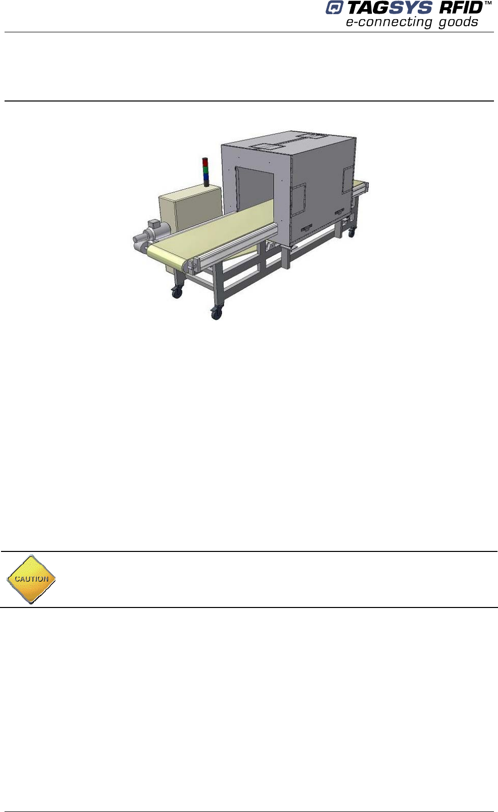
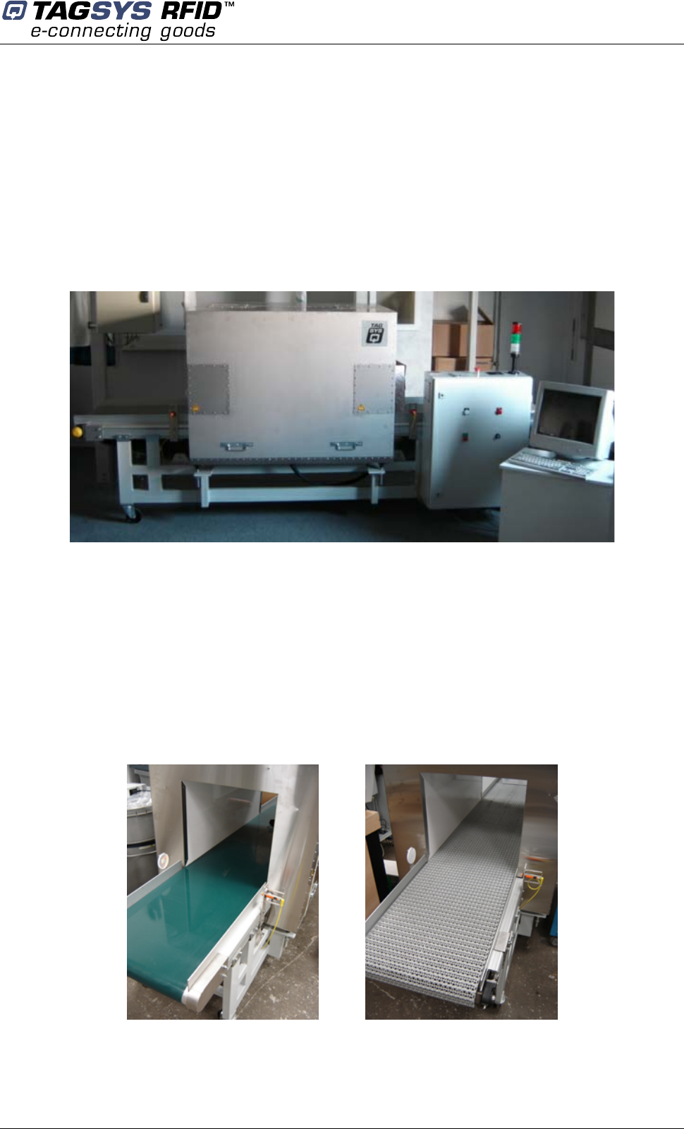
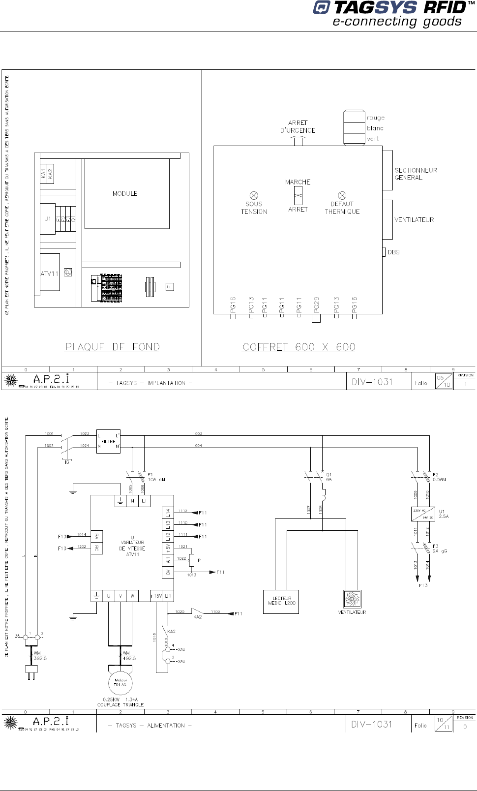
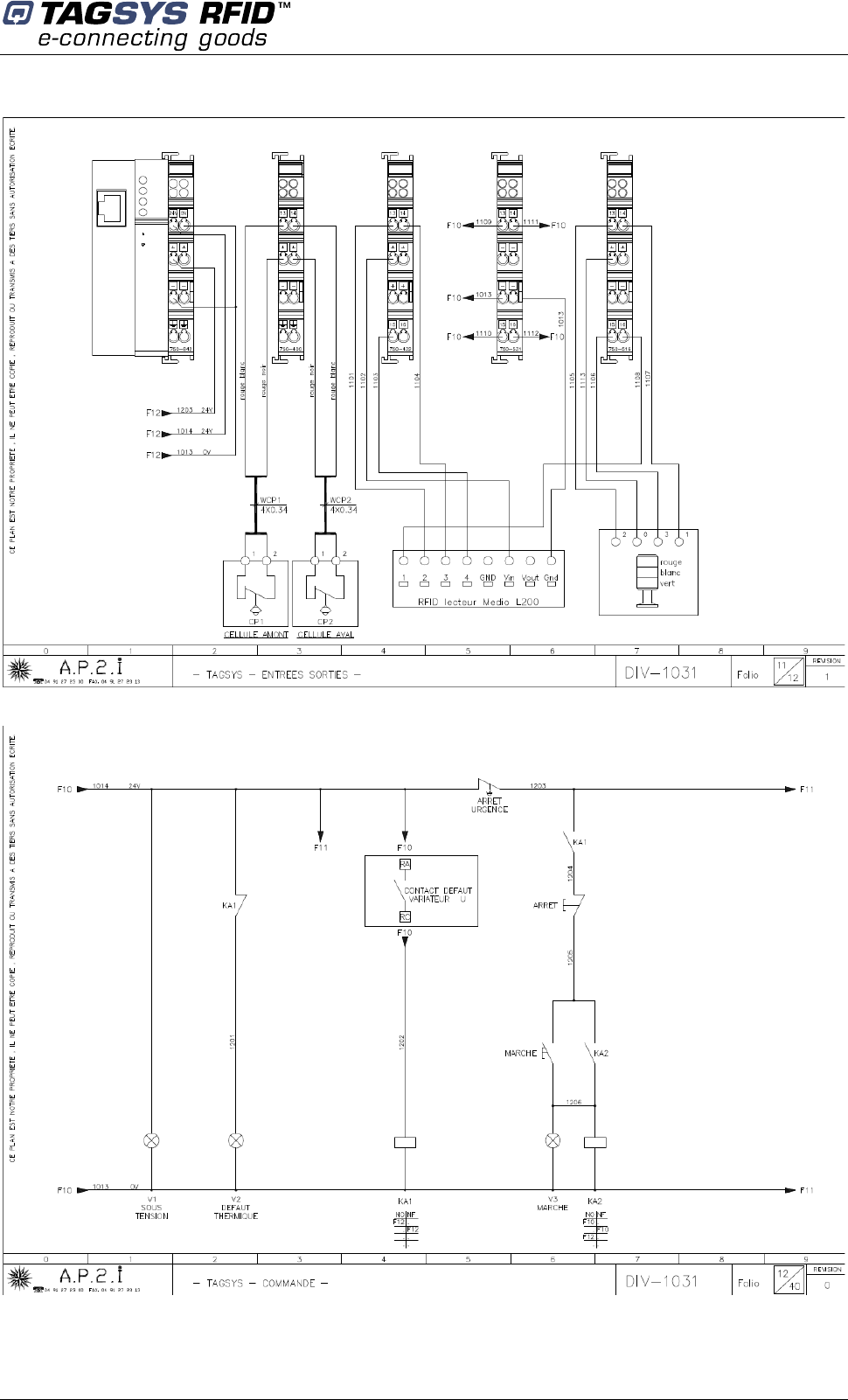
3.2 Brief Conveyor Tunnel Reader Description
Figure 1 : Conveyor Tunnel Reader
Being a standalone solution, TAGSYS Conveyor Tunnel Reader does not require additional
equipment to operate.
The CONVEYOR TUNNEL READER is made of three parts:
• The Tunnel (Electromagnetic shielded antenna arrangement)
• An electric cabinet including the RF reader and electrical devices to manage the conveyor.
The RF reader is based on the L200 TAGSYS reader with specific hardware and software
improvement for tunnel application.
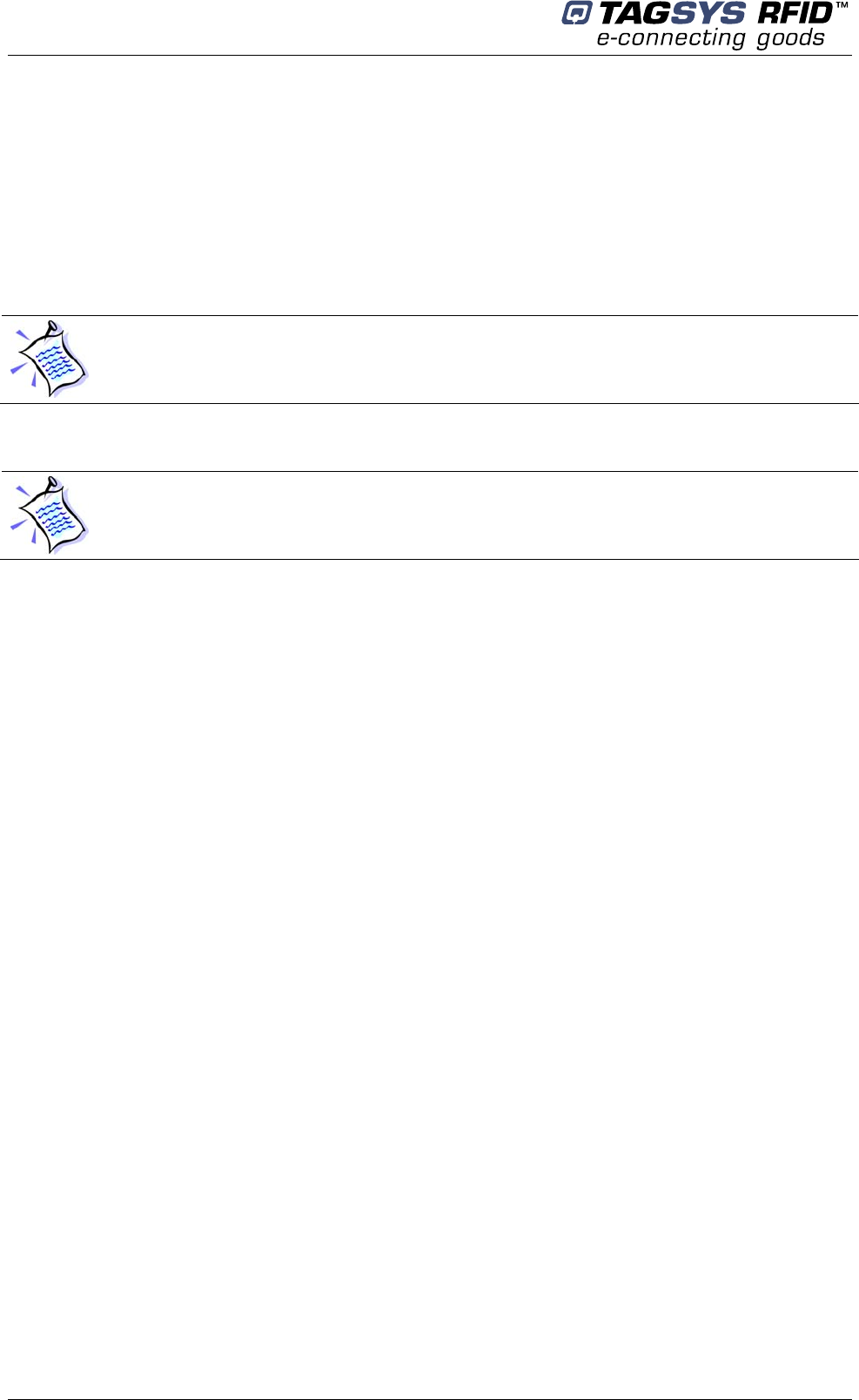
• The Conveyor, with a soft PVC belt or a plastic modular belt.
CONVEYOR TUNNEL READER User's Guide
16/45 Revision 1.0 November 2007
To operate, the Conveyor Tunnel Reader needs a power supply single-phase 110-120V AC / 60
Hz or 230V AC / 50Hz (depending on the version). Power consumption is less than 500W.
A RS232 serial cable is provided to connect the tunnel reader to the host PC, to collect and
manage data from the read tags.
Also provided, an Ethernet crossed cable for PLC command, and a DB25 parallel cable for RF
reader monitoring.
TAGSYS Medio L200 Reader for Tunnel (included in the electrical cabinet) is optimized for use
with TAGSYS TUNNEL antennas only.
The antennas are factory-calibrated to an impedance of 50 Ohms/ 0° that offers optimal
performances.
2 different mode to operate the CONVEYOR TUNNEL READER:
• standalone mode
• slave mode
They are described in following chapter.
The reader and the tunnel are fit together and cannot be used independently.
It is advised not to open tunnel to modify the antennas arrangement at the risk of loosing
performance and may conduct the TAGSYS TUNNEL READER to be unserviceable.
Modes of operation
November 2007 Revision 1.0 17/45
4 Modes of operation
4.1 Conveyor Tunnel Standalone Mode
In standalone mode no software application development is required. The tunnel is fully
autonomous, and the RFID reader sends automatically the read tags ID N° to the PC. The only
connection between host PC and the system is the serial RS232 cable to collect reader output data
(read tags can be displayed on the PC using Hyperterminal software).
The reader settings (baud rate, data frame format, RFID settings…) and PLC standard program
(ConvoyeurStandardDM_V2.pro) are loaded in the non volatile memory of the reader and the PLC
allowing tunnel to automatically run at power on.
TAGSYS Tunnels on conveyors are used to be delivered with customer application standalone
mode setting. The customer just has to push the green button on the front door of the electrical
cabinet to start the conveyor and place the tagged items on the conveyor.
4.1.1 RS232 Serial Communication Parameters
• baudrate: adjustable (9600, 18200 or 38400 bauds) – factory setting = 9600
• data bits: 8
• parity: none
• stop bit: 1
• flux control: none
• Frame format: Tag ID in hexadecimal, number of digits adjustable up to 16 (factory setting
= 16 digits)
• Trailer: adjustable – factory settings = carriage return + line feed (\0D\0A)
• Sorting: adjustable – factory settings = sorting activated (tag ID of a read tag is sent only
once by the reader)
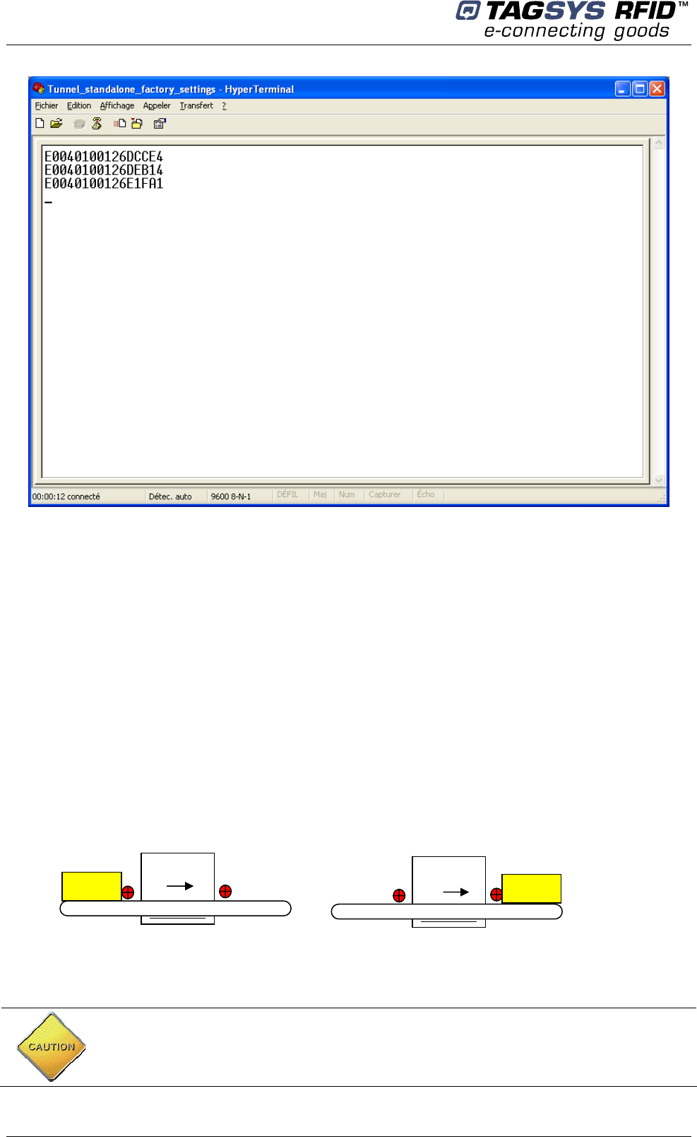
Below is an example of frames sent by the reader after 3 tags have been read (factory settings,
frames displayed on hyperterminal)
Uniqueness of tag ID can only be guaranteed if Tag ID is transmitted with 16 digits
Medio L200 reader cannot sort out more than 48 tags at a time, if more an additional sorting
sequence must be carried on by the customer application (otherwise the tunnel reader may
send several times the same tags ID)
CONVEYOR TUNNEL READER User's Guide
18/45 Revision 1.0 November 2007
4.1.2 Additional Features to Standalone Mode Frame Format
• CRC at the end of each ID frame
• sorting depth: minimal number of tags to be read before re-read the first one (max 48)
• sorting timeout: minimal time before re-read the first one
• watchdog characters and delay: check reader is still alive
All standalone reader parameters are adjusted using L200 Explorer software on the host PC.
Please refer to Chapter 8 and Medio L200 Reader User’s Guide for further information. These
parameters can easily be changed during/after installation.
For automation conveyor standard Standalone PLC program functionalities are as follow:
• Automatic start and stop of the RFID reading operation each time tagged items is going
through the tunnel (PLC manages upstream and downstream photocells information to
send an output trigger to the Medio L200 Reader) :
Trigger start Trigger stop
Photocells located at entry/exit of the tunnel are used to start and stop RFID reading
operations. If the container to read is too thin, it may not be detected by the photocell. If so,
the photocell must be placed just above the belt level, or the trigger features must be
cancelled in the standalone mode settings (permanent reading).
Tunnel
Box Tunnel
Box
Modes of operation
November 2007 Revision 1.0 19/45
• Counting or discounting number of boxes entering the tunnel trigger activation (trigger must
stop only when the last box has exited the tunnel). This feature is useful only when boxes
are moving one after the other.
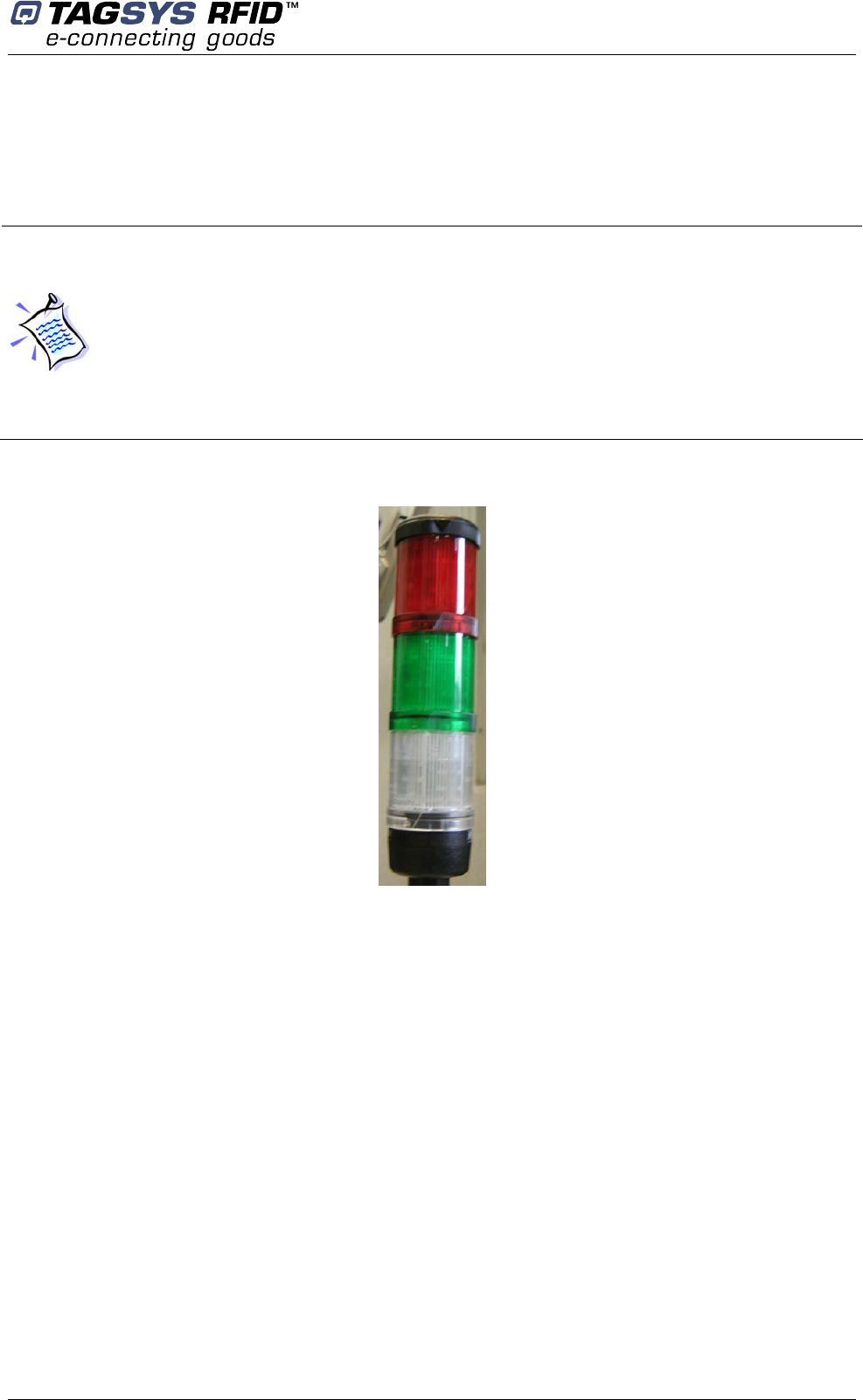
• A stacklight indicator is provided with the conveyor tunnel reader. It is not mounted at
delivery but can be easily plugged on top of the electrical cabinet.
Figure 2 : Indicating Lights
In standalone mode, Ethernet port on the WAGO PLC is not useful, unless the customer wants to
access (reading only) to the state of the inputs/outputs of the PLC (see below):
• Standard program loaded in the PLC (ConvoyeurStandardDM_V2.pro) does not run the
conveyor. Only buttons on the front door cabinet are used to start/ stop the conveyor.
Speed is adjusted using the potentiometer inside the electrical cabinet (nominal speed is
adjust by Tagsys during installation; it must not be changed without TAGSYS agreement).
• Optionally conveyor can be run in standalone mode if the program called
(ConvoyeurMoteurDM_V2.pro) is loaded in the PLC. The conveyor starts automatically
when the entry photocell sees the box (placed manually on the conveyor belt), and stops
automatically when the box exits the tunnel.
• Trigger features can be cancelled in the standalone mode settings and so the RF reading is
permanent at power on.
While operating the TAGSYS TUNNEL READER in standalone mode the stacklight (red,
green and white) will show process status.
1. White lamp is switched on when the RF field is ON. RF field is triggered by a box
crossing the optical sensor at the tunnel entry
2. Green lamp is switched on (for 500ms) when a new tag is read
3. Red lamp is switched on (for 500ms) after the box has crossed the tunnel and no
tag has been read
4. White lamp is switched off after a box has crossed the optical sensor at the tunnel
exit
CONVEYOR TUNNEL READER User's Guide
20/45 Revision 1.0 November 2007
4.2 Conveyor Tunnel Slave Mode
A custom software application has to be developed to fit with customer requirements. This software
application will drive the RFID Reader and the PLC conveyor.
The TAGSYS CONVEYOR TUNNEL READER is delivered with the STX-E standard protocol
application to operate in slave mode: the reader is the slave of the host PC or PLC and replies to
any STX-E command received. For more information about STX-E communication protocol, please
refer to the Lx00 Command Set documentation.
RS232 connection to the reader is used to set the reading parameters, start and stop the reading
or writing operations, etc. It will also be used to get the tags ID data exiting the reader.
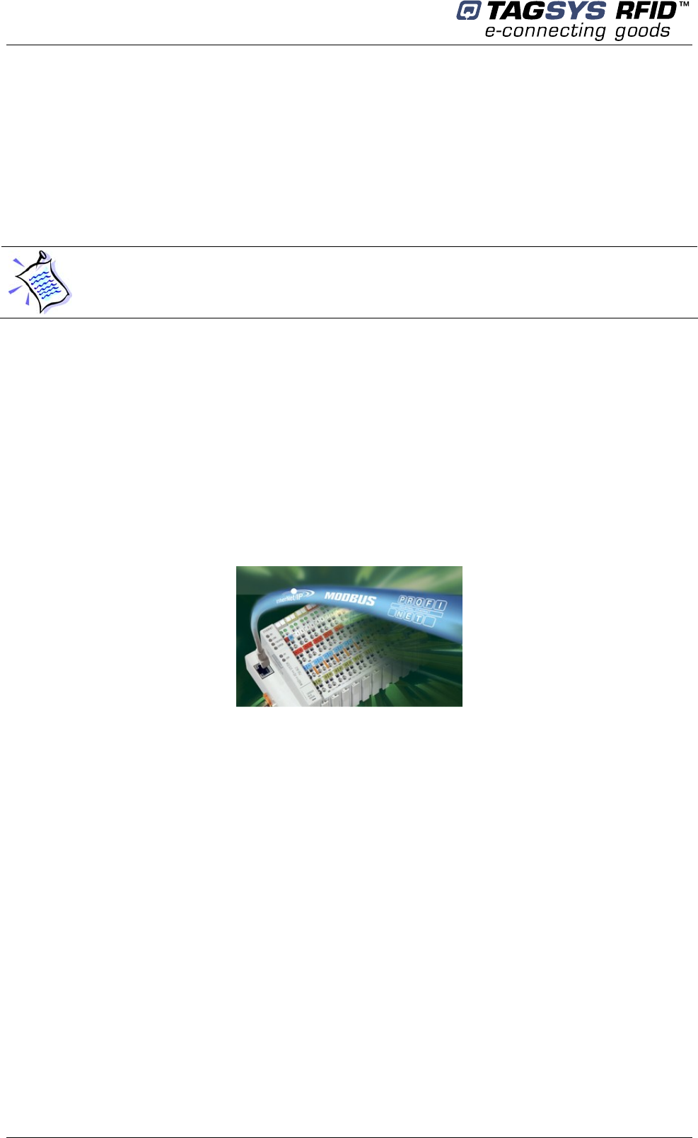
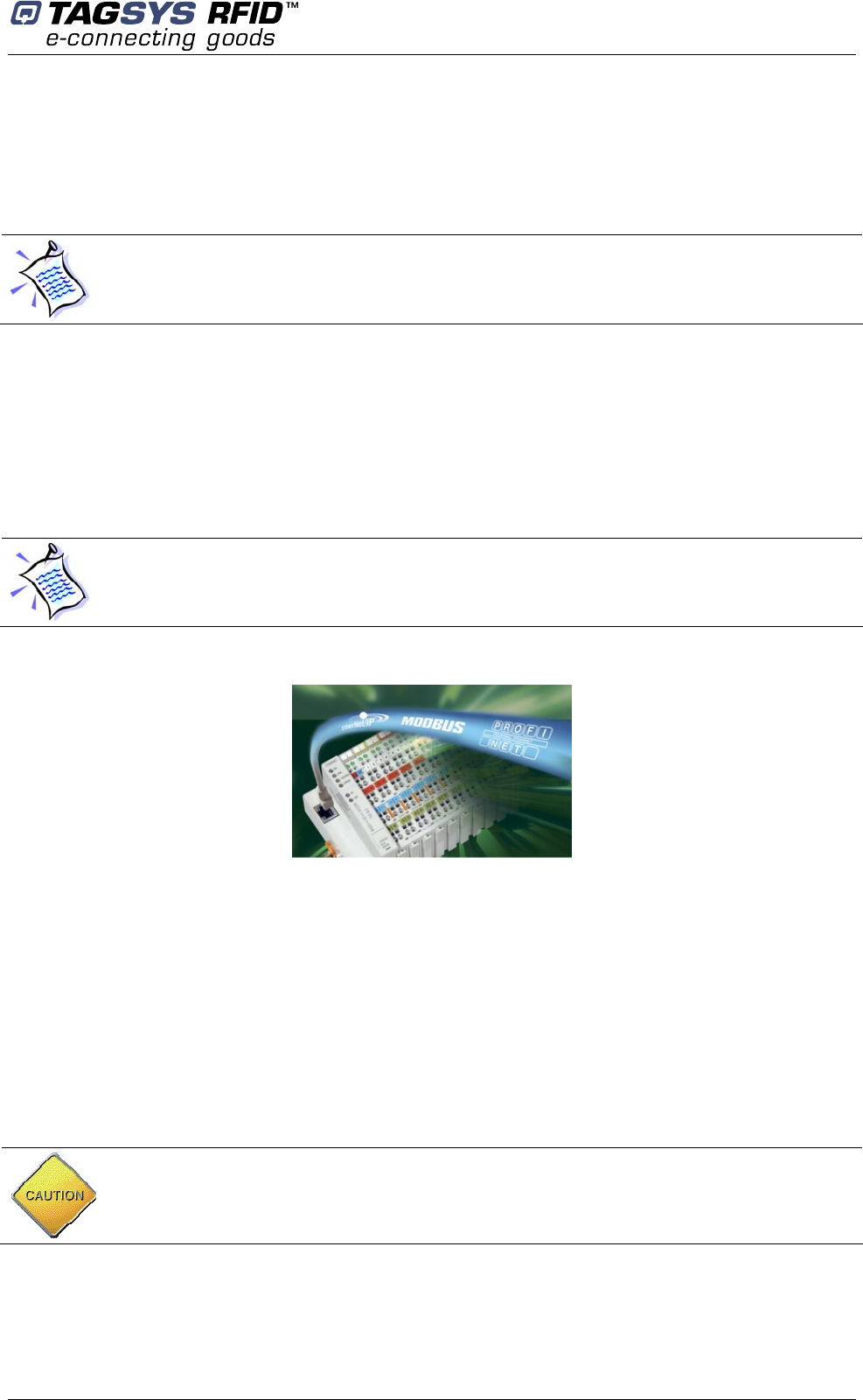
Ethernet/Modbus connection to the WAGO Controller can be used for external command of the
conveyor (reading of the state of any Input or Output, changing the state of any outputs Æ start,
stop, belt speed selection, etc).
TAGSYS can provide full commands set, DLLs and JAVA package for software developers to
develop their own application to drive the RFID reader.
WAGO DLLs (about $100 US) are also available for software developers to develop their own
application to drive PLC (conveyor) commands.
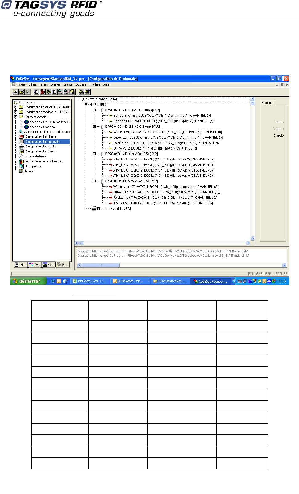
The PLC type is WAGO I/O System 750-842 TCP/IP Programmable Field Bus Controller equipped
with an Ethernet port. Standard IP address of the controller is 192.168.0.2.
List of PLC Inputs:
• Sensor In = photocell at the enter of the RFID tunnel
• Sensor Out = photocell at the exit o the RFID tunnel
• WhitelampL200, GreenlampL200n and RedlampL200 = not used in that mode
PLC Inputs reading can be used to:
• Trig the RFID reading
• Start any external operation
List of PLC Outputs:
• ATVL1, ATVL2, ATVL3, ATVL4 = outputs for conveyor start and speed management (see §
conveyor commands below)
• White-lamp, red-lamp, green-lamp = outputs corresponding to the stacklight
• Trigger = not used in that mode
PLC Outputs writing can be used to:
The STX-E Protocol is the TAGSYS standard protocol. It is compatible with all TAGSYS
products. We recommend using the STX-E protocol in order to address all TAGSYS reader
functions.
Modes of operation
November 2007 Revision 1.0 21/45
• start the conveyor forward or backward
• select one of the 3 preprogrammed conveyor speeds, or the speed adjusted by the
potentiometer inside the electrical cabinet
• light on any of the 3 lamps of the stack light
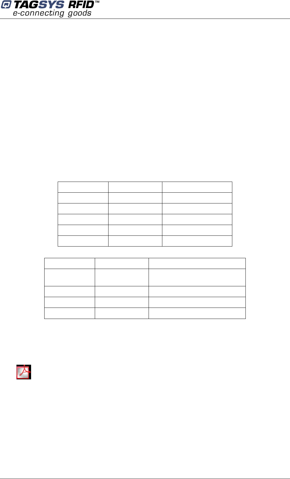
Here are the MODBUS bits addresses of the Inputs / Outputs of the WAGO controller
Identification Access Input
/Output Address
JBUS Address
Modbus
SensorIn Read In 0 1
SensorOut Read In 1 2
WhiteLampL200 Read In 2 3
GreenLampL200 Read In 3 4
RedLampL200 Read In 4 5
ATV_L1 Read / Write Out 512 513
ATV_L2 Read / Write Out 513 514
ATV_L3 Read / Write Out 514 515
ATV_L4 Read / Write Out 515 516
WhiteLamp Read / Write Out 516 517
GreenLamp Read / Write Out 517 518
RedLamp Read / Write Out 518 519
Trigger Read / Write Out 519 520
CONVEYOR TUNNEL READER User's Guide
22/45 Revision 1.0 November 2007
• To read the state of an Input from a supervisor, you need to make a read bit at the
corresponding address. Inputs, by definition, can not be modified.
• To read the state of an Output, you need to make a read bit at the corresponding address.
To modify the state of an Output, you need to make a write bit at the corresponding
address.
For more information on the variables addressing on WAGO I/O 750 system, please ask your
TAGSYS representative or go to http://www.wago.com/wagoweb/documentation/index_e.htm and
check manuals concerning 750-842 Ethernet TCP/IP Programmable Controller.
4.2.1 Conveyor Commands (for slave mode with external conveyor
command)
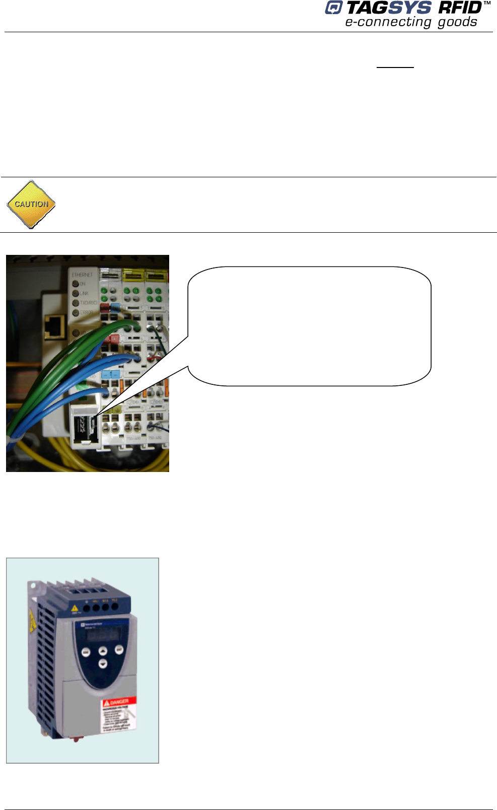
The conveyor motor is controlled by a Speed Variator Telemecanique Altivar 11.
Check the position of the small black switch on your PLC. It must be in the position
corresponding to your case (standalone or slave mode)
Small Black Switch
Upper position = standalone mode
Medium position = slave mode
Do not use lower position.
Modes of operation
November 2007 Revision 1.0 23/45
Altivar basic commands are available through following input:
• ATVL1 to ATVL4, that correspond to outputs on the WAGO PLC Controller):
• Stop
• Forward
• Backward
• SP3 (pre-programmed speed)
• SP2 (pre-programmed speed)
• SP4 (pre-programmed speed)
• Conveyor Speed from external potentiometer
See below Tables of settings and related actions:
ATVL1 to ATVL4 are 4 electrical inputs to command the motor speed variator (outputs from the
PLC):
Input ATVL1 Input ATVL2 Function
0 0 Stop
Front (0->1) 0 Forward
0 Front (0->1) Backward
1 Front (0->1) Nothing
Front (0->1) 1 Nothing
Input ATVL3 Input ATVL4 Speed
0 0 Potentiometer on conveyor front
panel
0 1 SP3 (pre-programmed)
1 0 SP2 (pre-programmed)
1 1 SP4 (pre-programmed)
These commands can be used to start and stop the conveyor depending on external conditions
(downstream saturation…).
Altivar User Guide
4.3 Tag compliance
The TAGSYS TUNNEL READER is designed for ISO15693 tags reading in Laundries,
Pharmaceutical, and retail warehouse or distribution centers.
Manuel_technique_
G
B.pdf
CONVEYOR TUNNEL READER User's Guide
24/45 Revision 1.0 November 2007
Table 1: Reader Chip Compatibility
Reader Compatible Chips
TAGSYS READER ISO 15693 (TAGSYS 370DL , CD tag 370 or FOLIO 370 tags)
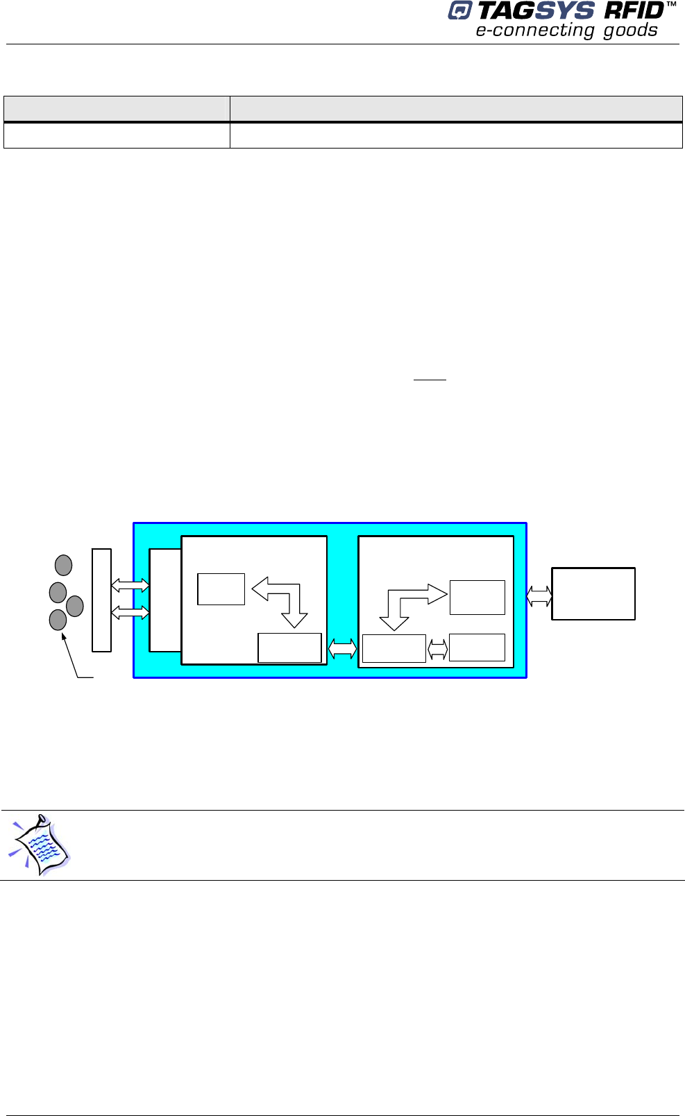
4.4 Architecture of the Included Long Range Reader
TAGSYS conveyor tunnel reader includes a Medio L200 Tunnel long range reader.
The 4 I/O reader ports are used to manage the stacklight indicator and trigger reading operation.
The Reader consists of two main parts: the Radio Processing Unit and the Data Processing Unit.
The Radio Processing Unit (RPU) manages the communication with the tags. This includes the
channel multiplexing management, RF output power levels and tag decoding. This part is built
around a high-performance Digital Signal Processor (DSP). Depending on the product reference,
the specific firmware associated to the DSP is downloaded into the DSP Flash memory. For more
details concerning the RPU architecture, please refer to the Lx00 Full Firmware Reference Guide.
The Data Processing Unit (DPU) consists of the GemCore® OS. The DPU controls the serial
communication link, I/O ports, and commands sent to the DSP. Custom application software can
be downloaded into the DPU. The standard application software is the TAGSYS STX-E
communication protocol.
Figure 3: Lx00 Reader Architecture
Data Processing Unit
Serial
Interface
HPI
Interface
DSP
Unit
RF Channels
GemCore
OS
Radio Processing Unit
Radio Frequency
I/O
Interface
External I/Os,
Interrupts and
Triggers
Tags
For set up, debug or monitoring purpose, the Host PC communicates directly with the DSP via the
Monitoring port. When the Monitoring port is in use, the DPU block (I/O ports and serial
communication link) is disabled.
4.5 TAGSYS Conveyor Tunnel Reader Connections
4.5.1 Serial Connector
The DB9 serial connector on the electrical cabinet is used to communicate with an external
environment (host PC).
• In standalone mode, this port transmits tags data to the host PC (Please refer to chapter
4.1).
Please refer to the Lx00 Firmware Reference Guide for further information about
CONVEYOR TUNNEL READER Firmware.
Modes of operation
November 2007 Revision 1.0 25/45
• In slave mode, user commands and data exchanges are transmitted through this port. It
can be set to RS-232, RS-485 or RS-422 mode by software. Different baudrates are
available to each mode.
Refer to Serial Port Pin Assignment for more details about cabling serial links.
Tx (Transmit Data) and Rx (Receive Data) LEDs indicate the activity of the serial port.
4.5.2 Monitoring Port (Parallel Port)
This port (connector on the RFID reader inside the electrical cabinet) is dedicated to monitoring the
reader. (Not to be used with customer application)
The monitoring port communicates directly with the DSP firmware stored in the Flash memory.
When the parallel cable is plugged in, the GemCore® OS and STX application software is
automatically deselected. The parallel port can be used as a monitoring tool or as a means to set
up or debug the CONVEYOR TUNNEL READER via the L200 Explorer.
4.5.3 Ethernet Port on the PLC Controller
This port is devoted to external monitoring of the PLC, for customized conveyor command or I/O
management.
The RJ45 connector is on the WAGO PLC, inside the electrical cabinet of the Conveyor Tunnel
Reader.
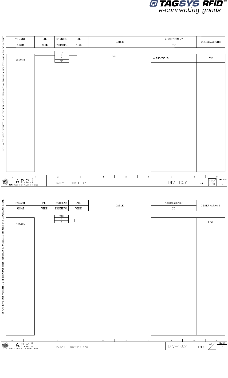
4.5.4 Main Power Supply
A 3-pole shielded cable of section >=3G2,5² must be connected by a sworn electrician directly on
the electrical terminals N°1, 2, and 3 inside the electrical cabinet.
Yellow / green terminal refer to the ground cable.
Conveyor Tunnel Reader power consumption less than 500W.
The RS-232 cable is a null modem cable.
The parallel cable uses pin-to-pin DB25 connectors. A shielded cable must be used to prevent
disruptions when antennas have a high output power.
CAUTION: 2 versions of Conveyor Tunnel Reader are available: 230VAC/50Hz and
110VAC/60Hz power supply.
Therefore check carefully the version before connecting the power cable.
CONVEYOR TUNNEL READER User's Guide
26/45 Revision 1.0 November 2007
5 Installation
5.1 Conveyor Tunnel Reader
5.1.1 Installing
After having defined the location of the Conveyor Tunnel Reader, immobilize it by applying the
brakes on at least two of the four conveyor wheels.
Conveyor elevation can be adjusted by acting on the feet position (2 screws on each foot).
Then, connect the power cable to the electrical terminal, and the plug the host PC to the serial port.
CAUTION: This equipment is intended for indoor use only under the conditions described in
this document. Should it be used outside these conditions cannot be guaranteed, and is not
recommended. Please read section 1“ For Your Safety “ before installation or use.
Operation
November 2007 Revision 1.0 27/45
6 Operation
6.1 Starting the System
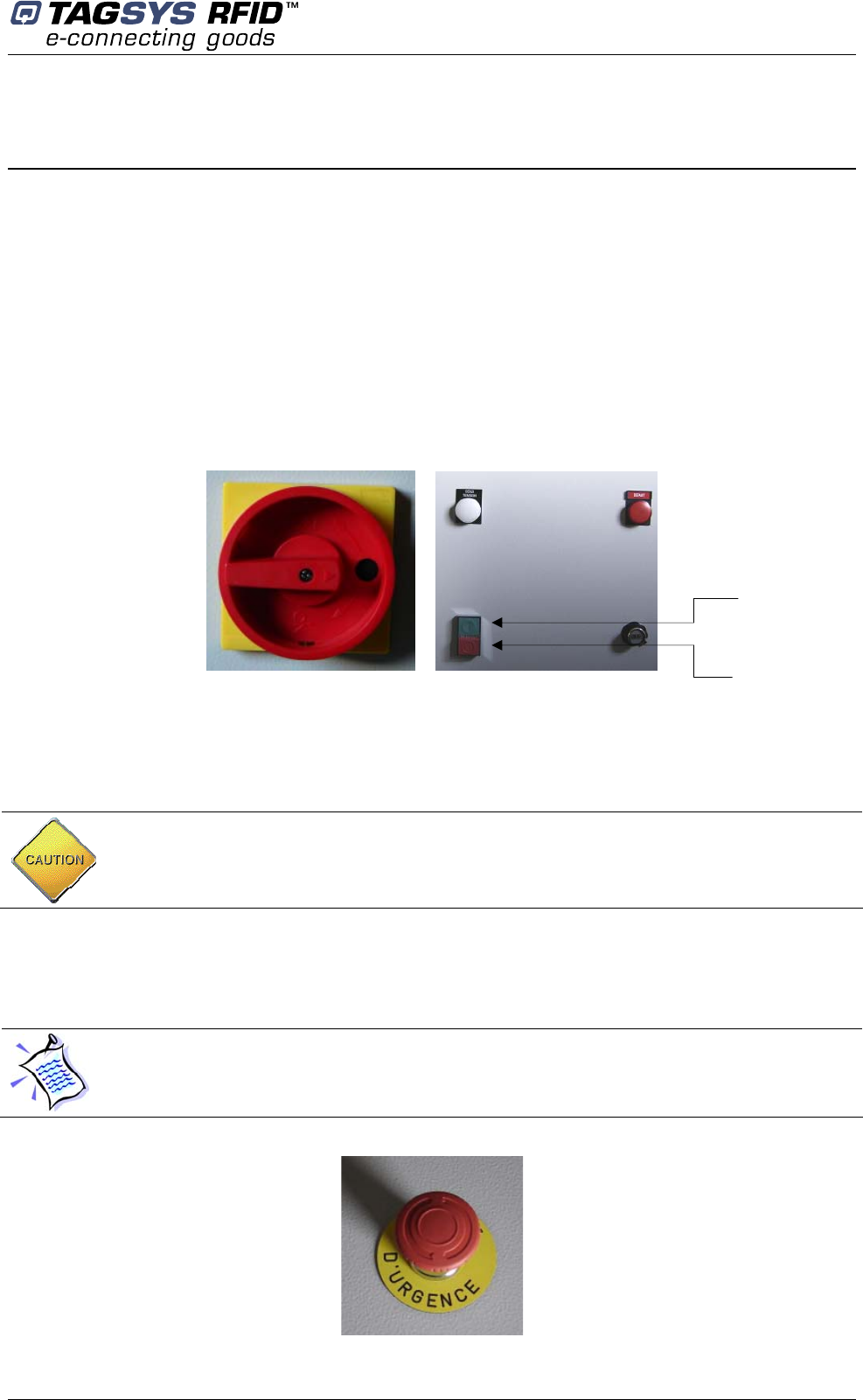
• To power on the system, switch on the main power switch.
• To start and stop the conveyor, use the red and yellow pushbuttons. If in standalone mode,
the reading will start and stop automatically as a batch of items is going through the tunnel.
Tags ID will also be transmitted automatically on the serial link.
Left picture shows the main power switch located on the edge of the electric cabinet.
Right picture shows the START/STOP push buttons for the conveyor.
Figure 4: Switches and push buttons
6.2 Normal Operation
No operating procedures are required. The system continues to operate as long as power is
supplied.
6.3 Shutdown
Stop the conveyor by pressing the red pushbutton, and then turn off the main power switch.
Figure 5: Emergency button
Avoid letting the conveyor running all day long if not necessary.
In case of emergency push the red button located at the top of the electric cabinet to stop the
Tunnel reader conveyor.
Press green button to
start conveyor
Press red button
to stop conveyor
CONVEYOR TUNNEL READER User's Guide
28/45 Revision 1.0 November 2007
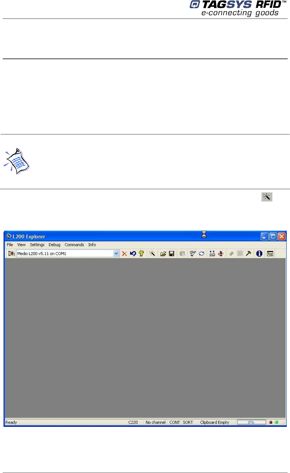
7 Using the L200 Explorer
The TAGSYS L200 Explorer is utility software that enables the user to identify the current smart
label reader system or system components (reader reference, firmware version, supported chips,
etc.) and to perform the following tasks:
• Perform debug operations and reading tests
• Configure the reader for operation in Standalone mode
• DSP firmware upgrades
The L200 Explorer resembles a typical Windows®-based user interface. A Wizard function is
provided to guide the user through each step of how to read or program specific smart labels
(tags).
Figure 6: L200 Explorer
An on-line help function is included (CTRL+H).
For optimal performances during debug operations, the Lx00 reader must be connected via
the monitoring port, using a parallel cable (supplied), to the host PC running the L200
Explorer software.
However, a serial connection is also possible if the STX-E GemCore® application, version 2.0
or more recent, is downloaded into the Medio™ Lx00 Reader. In this case, performances may
be affected.
The STX-E Standalone mode can only be configured using the serial communication link.
Using the L200 Explorer
November 2007 Revision 1.0 29/45
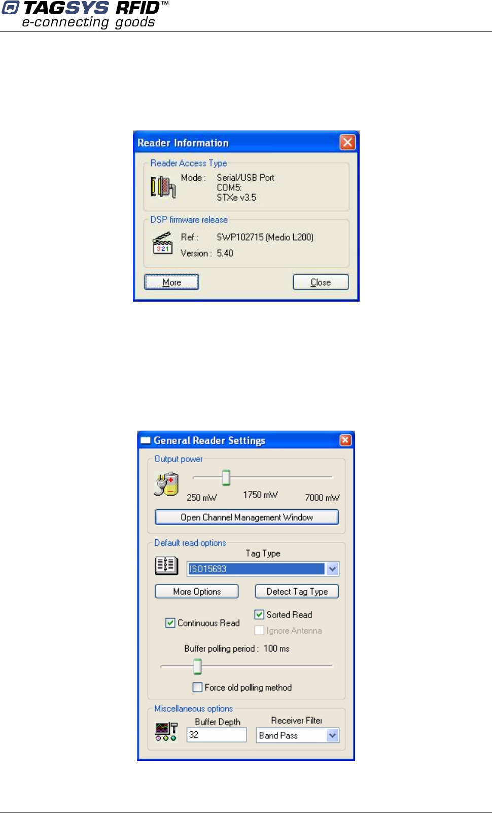
7.1 Reader Information
To display the current Reader Access type and DSP Firmware version, in the Info menu, select
Reader Information (CTRL + I).
Figure 7: Reader Info (Example)
Click More to display the list of additional features and supported chip types.
7.2 General Reader Settings
The General Reader Settings dialog box (CTRL + G) in the Settings menu is used to set the reader
parameters in order to test a given application. Several parameters can be set; i.e. antenna RF
power, channel multiplexing, chip type, read mode, etc.
Figure 8: General Reader Settings (Example)

CONVEYOR TUNNEL READER User's Guide
30/45 Revision 1.0 November 2007
7.3 Debugging Tools
The Lx00 Reader features debugging tools to optimize your RFID system installation and
communication with the tags. Debugging tools consist of:
• A real-time oscilloscope to display the antenna signals received by the Lx00 Reader,
• A real-time frequency analyzer to display the frequency information of the antenna signal,
• Certain statistical information about the quality of your RFID system environment.
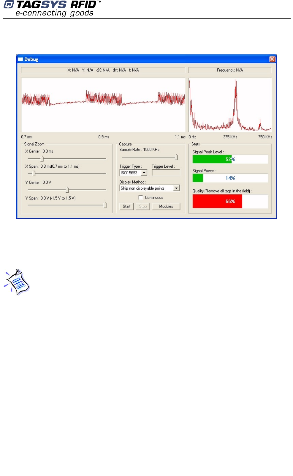
7.3.1 Debug Dialog Box
Medio Lx00 Readers can be debugged to locate possible decoding problems due to ambient noise.
The L200 Explorer provides an oscilloscope graphics display enabling the user to capture and
display the receiver analog signal and its Fast Fourier Transform. Of course, one of the channels
must be enabled.
The Debug dialog box also displays several indicators concerning the quality of the reader
performance. For more information, please refer to the L200 Explorer User's Guide.
Please refer to “L200 Explorer User’s Guide” for further information about debugging tools.
Using the L200 Explorer
November 2007 Revision 1.0 31/45
Figure 9: Debug Dialog Box
7.4 Standalone Mode Configuration
Standalone Mode is designed to use the reader without using any command set. While in this
mode, the reader is limited to tag reading.
The Standalone Configuration Mode dialog box is used to define all parameters of the Standalone
mode: chip type, frame format, baud rate, etc. For more information, please refer to Section 8.2,
"L200 Reader Standalone Mode" and the L200 Explorer User's Guide.
Requirements: The STX-E GemCore® application, version 2.0 or more recent, must be
downloaded into the Lx00 Reader. In addition, the serial communication link must be used to
configure Standalone mode using the L200 Explorer.
CONVEYOR TUNNEL READER User's Guide
32/45 Revision 1.0 November 2007
8 L200 Reader Configuration
The purpose of this chapter is just to provide guidelines that may be useful for customers who
need to configure the Medio L200 Reader for tunnel that is included in the Conveyor Tunnel reader
(for a modification of standalone mode parameters or for the development of an application in
slave mode).
The GemCore® Development Kit is also available for developing custom on-board applications
other than the one supplied.
8.1 L200 Reader Slave Mode Configuration
The host PC or PLC is the master of the serial communication links. In this mode, the Lx00 reader
replies to any STX-E command sent by the host PC or PLC. All Lx00 reader resources are
accessible via the STX-E commands (I/O ports, serial communication type, DSP features, etc.).
For more information, please refer to the Lx00 Reader Full Command Set documentation.
8.2 L200 Reader Standalone Mode Configuration
The Standalone Module included in the STX-E application software is used to generate an ASCII
message frame with configurable data fields.
Standalone mode features can only be configured using the L200 Explorer software.
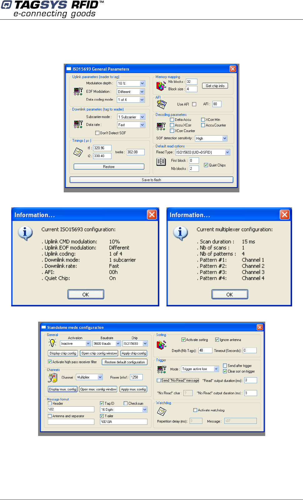
8.2.1 General Parameters
These parameters are used to define:
• Standalone Activation mode: Start upon next reset, Start Now or Inactive.
• Communication Baud rate: 4800, 9600, 19200 or 38400 bauds can be selected. Other
parameters are set to standard values: No parity, 1 stop bit and 8-bit characters.
• Chip Type to be read in Standalone mode: Only one single chip type can be selected in
Standalone mode. Depending on the selected chip type, specific chip parameters can be
configured.
• To improve reading performances when using high-quality factor antennas or when the
antenna RF power is greater than 1.5 W, select Activate High Pass Receiver Filter to set
the receiver filter to High Pass filter mode.
8.2.2 Channel Parameters
These parameters are used to define the general channel configuration:
• RF antenna output power (between 250 mW and 4 W for L100 platforms)
• Channel mode: Either one single channel or a Multiplex configuration is enabled. If no
channel is selected, all channels are switched off and no tag commands can be executed.
When one channel is selected, it is switched on immediately.
Requirements: The STX-E GemCore® application, version 2.0 or more recent, must be
downloaded into the Medio™ Lx00 Reader. In addition, the serial line must be used to
configure Standalone mode using the L200 Explorer.
L200 Reader Configuration
November 2007 Revision 1.0 33/45
If Multiplex mode is selected, all channels are switched off. In this case, the reader uses the
multiplexer patterns during default read operations. In Multiplex mode, only the default Standalone
read command can be executed. For more information, please refer to Section 4 of the Lx00 Full
Firmware Reference Guide.
8.2.3 Tag Message Frame Format
The format of the ASCII message used in Standalone mode is user-defined. The Header and
Trailer strings are optional, as is the Antenna (RF channel) and its separator string. The Tag ID
field contains the tag ID. The number of tag ID characters to be displayed can also be defined.
An optional Checksum field is available to verify the validity of the data.
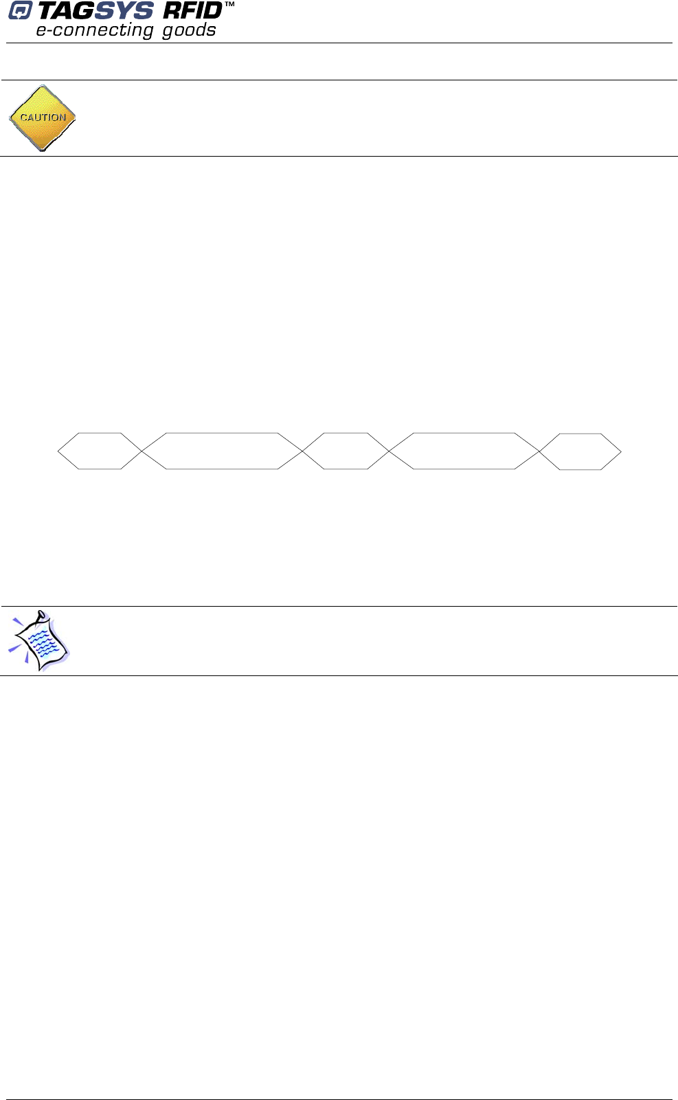
Messages are sent in frames with the elements shown in Figure 10. The elements sent in the
message can be individually selected.
Figure 10: Tag Message Frame Format
Header Ant. No. + Separator Tag ID Separator + CRC Trailer
The Header and Trailer can each contain from 1 to 16 characters or be absent. Their presence is
independent of one another.
The Antenna Number is from 1 to 4 depending on the product reference. This Separator can
contain between 1 and 16 characters.
The number of ASCII characters in the ID field can be configured between 2 and 16.
The second Separator can contain between 1 and 16 characters. The CRC field is the XOR of the
sum of all the characters (in hexadecimal format) included in the message. Two ASCII characters
represent this value.
8.2.4 Sorting Parameters
The Standalone module of the STX-E on-board software application features a Sorting mode. In
normal conditions, each tag frame is sent to the host PC or PLC as soon as it is decoded by the
Lx00 Reader.
In Sorting mode, the tags are sorted by the Lx00 Reader before the tag frames are sent to the host
PC or PLC. The tags are sorted by a combination of three parameters selected by the user.
• Buffer depth: between 1 and 50 frames
• Timeout per tag: between 0 and 255 seconds in steps of 1 second.
• Reader sorts tags by antenna or regroups all tags into a single group
8.2.5 Trigger Parameters
Standalone mode is able to function using an external trigger. In this Trigger mode, the I/O ports
are used with the following functions:
CAUTION: Antennas MUST be connected to the reader unit before the Channel settings are
enabled.
The ID Field is always present.

CONVEYOR TUNNEL READER User's Guide
34/45 Revision 1.0 November 2007
I/O 1: Trigger (input)
I/O 2: Copy of trigger (output)
I/O 3: Active when tag is correctly read (output)
I/O 4: Active when no tag has been read after a trigger (output)
The trigger function operates based on the voltage level; i.e. active high or active low. The IDs of
tags detected when the trigger is active can either be sent immediately or after the trigger is reset
(inactive). If no tags are detected during a valid trigger condition, a specific character string can be
sent. This character string is called a "No Read" message and can be defined by the user. This
string replaces the tag ID field in the tag message frame.
The output duration of I/Os 3 and 4 can be individually set for a time between 0 and 63750
milliseconds in steps of 250 milliseconds. These outputs are generally used in connection with a
signal box.
8.2.6 Watchdog
A Watchdog function is available. A specific user-defined ASCII message can be regularly sent.
The Repetition Delay can be set up to 63750 milliseconds in steps of 250 milliseconds.
In Trigger mode, the antenna RF field is switched on only when the trigger is activated.
L200 Reader Configuration
November 2007 Revision 1.0 35/45
8.2.7 Typical Standalone Mode Parameters for 370DL Laundry Tag Reading
CONVEYOR TUNNEL READER User's Guide
36/45 Revision 1.0 November 2007
9 Technical Specifications
9.1 Technical Specifications
Table 2: Technical Specifications
Parameter Value
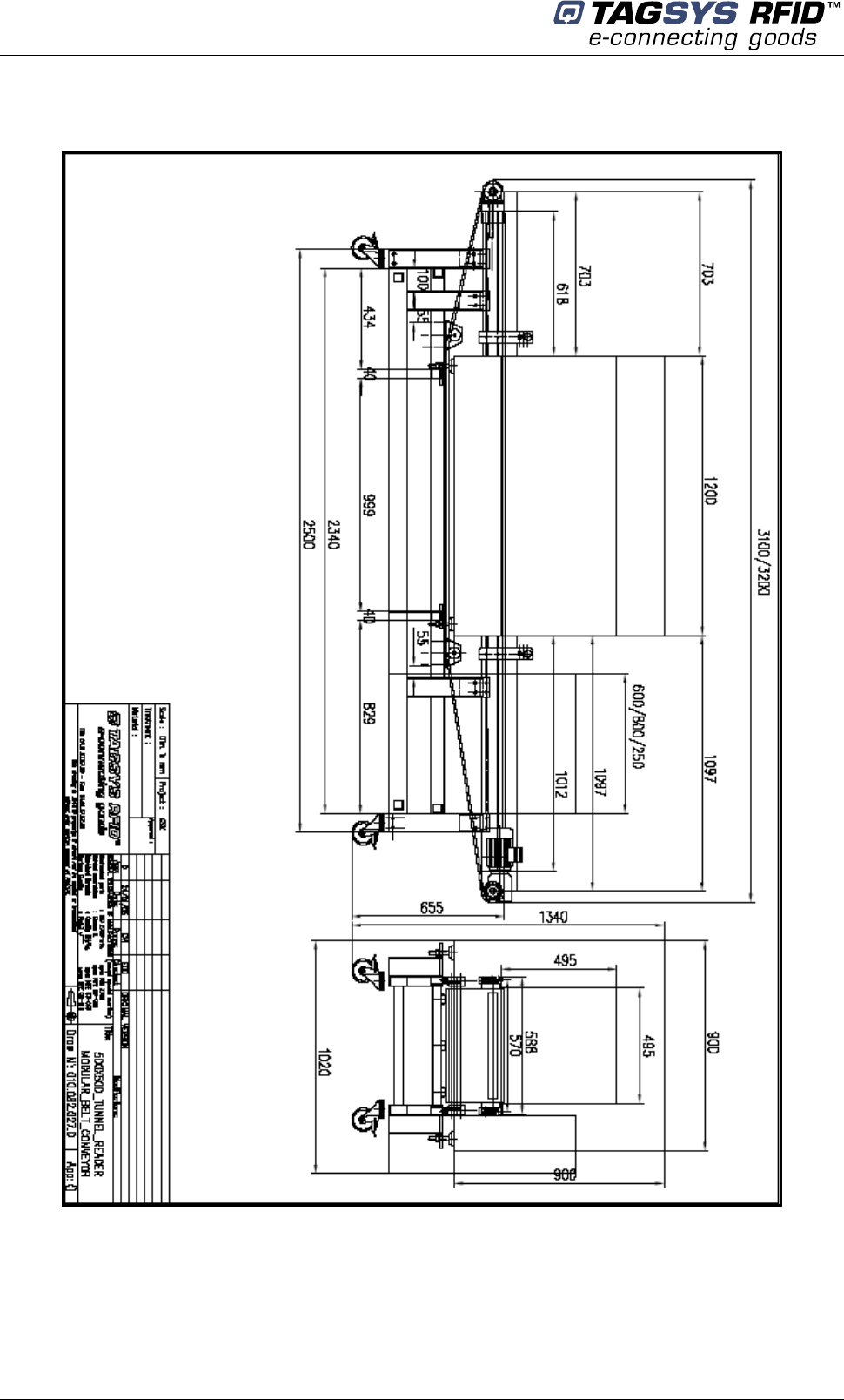
Size (L x W x H) Please see Figure 13
Weight 330kg. (727.5lbs.)
Ambient Operating Temperature 0 °C to 55 °C (32 °F to 131 °F)
Storage Temperature –20 °C to 70 °C (–4 °F to 158 °F)
Power Supply 110 o 120 V AC / 60 Hz or 230V AC / 50 Hz
Communication Speed Serial: Up to 38400 Kbps
Communication Interface Serial: RS-232, RS-485 and RS-422
Parallel: Bi-directional and Enhanced
RF Output Power Up to 7 W
with multiplex capability and balanced 0° / 180° operation
Power Consumption Up to 500W (maximum)
L-200 reader Conformity
CE
EN 300-330, ETS 300-683 European Radio
FCC Part 15 (for typical configurations)
Embedded Application Software 512 KB of Flash memory
Reader Inputs/Outputs 4 I/O ports (Using I/Os in STX-E Standalone Mode)
PLC Inputs/Outputs
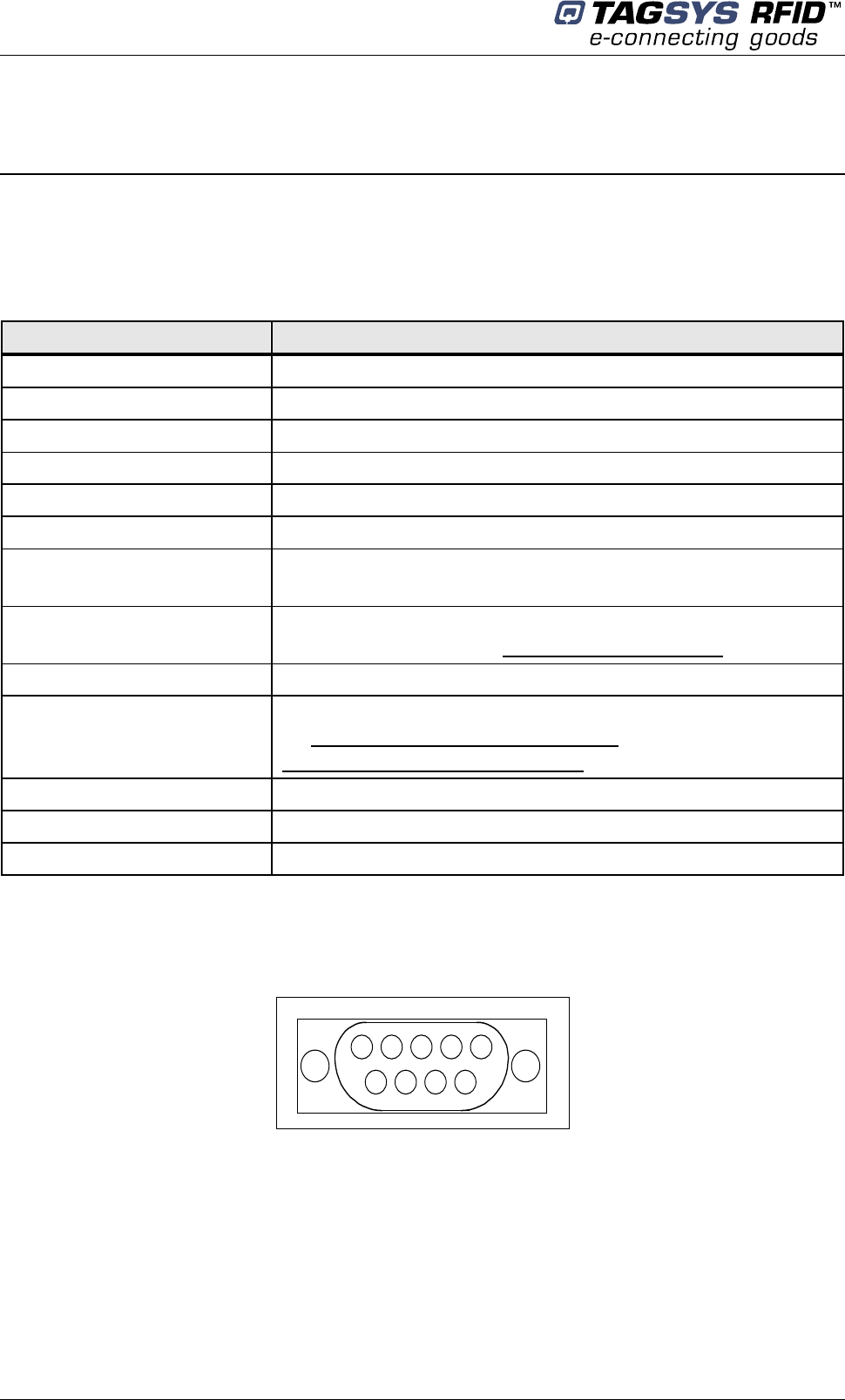
9.1.1 Serial Port Pin Assignment
Figure 11: DB9 Serial Connector
12345
6 7 8 9
Technical Specifications
November 2007 Revision 1.0 37/45
Connector Description Connector Description
1 NC 6 TRx+ RS485/ Rx+ RS422
2 Rx RS232 / TRx- RS485 / Rx- RS422 7 NC
3 Tx RS232 / TRx- RS485 / Tx- RS422 8 NC
4 NC 9 TRx+ RS485/ Tx+ RS422
5 NC
Following pages show the mechanical and electrical characteristics of the CONVEYOR TUNNEL
READER.
Figure 12
CONVEYOR TUNNEL READER User's Guide
38/45 Revision 1.0 November 2007
Figure 13 Mechanical Dimensions
Technical Specifications
November 2007 Revision 1.0 39/45
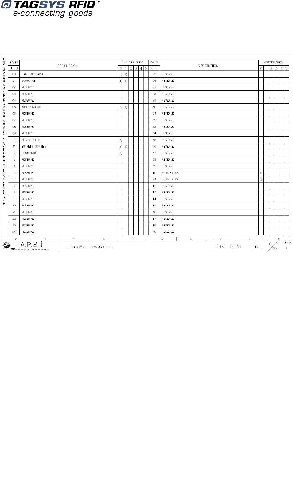
Figure 14
CONVEYOR TUNNEL READER User's Guide
40/45 Revision 1.0 November 2007
Figure 15
Figure 16
Technical Specifications
November 2007 Revision 1.0 41/45
Figure 17
Figure 18
CONVEYOR TUNNEL READER User's Guide
42/45 Revision 1.0 November 2007
Figure 19
Figure 20

Warranty Conditions
November 2007 Revision 1.0 43/45
10 Warranty Conditions
TAGSYS warrants that this Product shall comply with the functional specifications set forth herein
for a period of one year from the date of delivery to the Buyer.
This warranty is valid for the original Buyer of the Product and is not assignable or transferable to
any other party.
TAGSYS cannot be responsible in any way for, and disclaims any liability in connection with the
operation or performance of:
Any product in which the Product is incorporated;
Any equipment not supplied by TAGSYS which is attached to or used in connection with
the Product; or
The Product with any equipment
This warranty does only cover the Product to the exclusion of any such other equipment.
Optimal operation and performance of the Product are obtained by using TAGSYS’ readers, by
applying TAGSYS installation guidelines and by having your installation reviewed by a TAGSYS’
technical consultant.
TAGSYS warranty does not cover the installation, maintenance or service of the Product and is
strictly limited to the replacement of Products considered as defective by TAGSYS and returned
according to the return procedure defined below; in such case, TAGSYS will, at TAGSYS’ option,
either replace every defective Product by one new Product or refund the purchase price paid by
Buyer to TAGSYS for the defective Product.
10.1 Warranty Exclusions
Defects or damages resulting from storage of the Product under conditions which do not
comply with TAGSYS specifications or normal usage
Defects or damages resulting from use of the Product in abnormal conditions (abnormal
conditions being defined as any conditions exceeding the ones stated in the product
specifications).
Defects or damages from misuse, accident or neglect.
Defects from improper testing, operation, maintenance or installation.
Defects from alteration, modification except modifications or adjustments specifically described
in this Product reference guide, adjustment or repair, or any attempt to do any of the foregoing,
by anyone other than TAGSYS.
Any action on Product that prevents TAGSYS from performing an inspection and test of the
Product in case of a warranty claim.
Tampering with or abuse of the Product.
Any use or incorporation by the Buyer or a third party of TAGSYS' Product into life saving or life
support devices or systems, or any related products, TAGSYS expressly excludes any liability
for such use.
10.2 General Provisions
This warranty sets forth the full extent of TAGSYS responsibility regarding the Product.

CONVEYOR TUNNEL READER User's Guide
44/45 Revision 1.0 November 2007
In any event, TAGSYS warranty is strictly limited to (at TAGSYS’ sole option) the replacement or
refund of the Products purchase price to TAGSYS, of Products considered as defective by
TAGSYS.
The remedy provided above is in lieu and to the exclusion of all other remedies, obligations or
liabilities on the part of TAGSYS for damages, whether in contract, tort or otherwise, and including
but not limited to, damages for any defects in the Products or for any injury, damage, or loss
resulting from such defects or from any work done in connection therewith or for consequential
loss, whether based upon lost goodwill, lost resale profits, impairment of other goods or arising
from claims by third parties or otherwise.
TAGSYS disclaims any explicit warranty not provided herein and any implied warranty, guaranty or
representation as to performance, quality and absence of hidden defects, and any remedy for
breach of contract, which but for this provision, might arise by implication, operation of law, custom
of trade or course of dealing, including implied warranties of merchantability and fitness for a
particular purpose.
10.3 How to Return Defective Products
The Buyer shall notify TAGSYS of the defects within 15 working days after the defects are
discovered.
Defective Products must be returned to TAGSYS after assignment by a TAGSYS Quality
Department representative of an RMA (Return Material Authorization) number. No Products shall
be returned without their proof of purchase and without the acceptance number relating to the
return procedure.
All Products must be returned in their original packaging.
All Products shall be returned with a report from the Buyer stating the complete details of the
alleged defect.
Call +33 4 91 27 57 36 for return authorization and shipping address.
If returned Products prove to be non-defective, a charge will be applied to cover TAGSYS’ analysis
cost and shipping costs.
If the warranty does not apply for returned Products (due to age, or application of a warranty
exclusion clause), a quote for replacement will be issued, and no replacement will be granted until
a valid purchase order is received. If no purchase order is received within 30 days after the date of
TAGSYS quote, TAGSYS will return the products and charge the analysis cost and shipping costs.
All replaced Products shall become the property of TAGSYS.
The Product Return Form is included on the following page. This form should accompany any
product you need to return to TAGSYS for analysis in the event of a problem.
Warranty Conditions
November 2007 Revision 1.0 45/45
Product Return Form
Customer Profile:
Company: ................................................................
Address: ..................................................................
.................................................................................
.................................................................................
City & State:.............................................................
Zip Code: .................................................................
Country: ...................................................................
Contact Name: .......................................................
Contact e-mail: ......................................................
Contact Phone: ......................................................
Contact Fax:...........................................................
Order identification:
Product Name:.........................................................
Order Number (OEF):..............................................
Invoice Number: .....................................................
Return Quantity: ....................................................
Reason for return:
.........................................................................................................................................................................
.........................................................................................................................................................................
.........................................................................................................................................................................
.........................................................................................................................................................................
.........................................................................................................................................................................
To inform TAGSYS of this return, please email it to
RMA@tagsysrfid.com
Address to ship the product with this document attached:
TAGSYS
QUALITY DEPARTMENT
180, chemin de Saint Lambert
13821 La Penne sur Huveaune France
To inform TAGSYS of this return, please also fax it to your Customer Service Representative
+33 4-9127-5701
Return Procedure:
The product returned will go through stringent quality controls.
A final analysis report will be sent to you as soon as possible.
Please contact your Quality Service representative for further details.
+33 4-91-27-5736