Tagsys LSP3STANDARD RFID Tag Reader User Manual L SP3 UserGuide DOC13259A1
Tagsys S.A. RFID Tag Reader L SP3 UserGuide DOC13259A1
UserManual.wiki
>
Tagsys
>
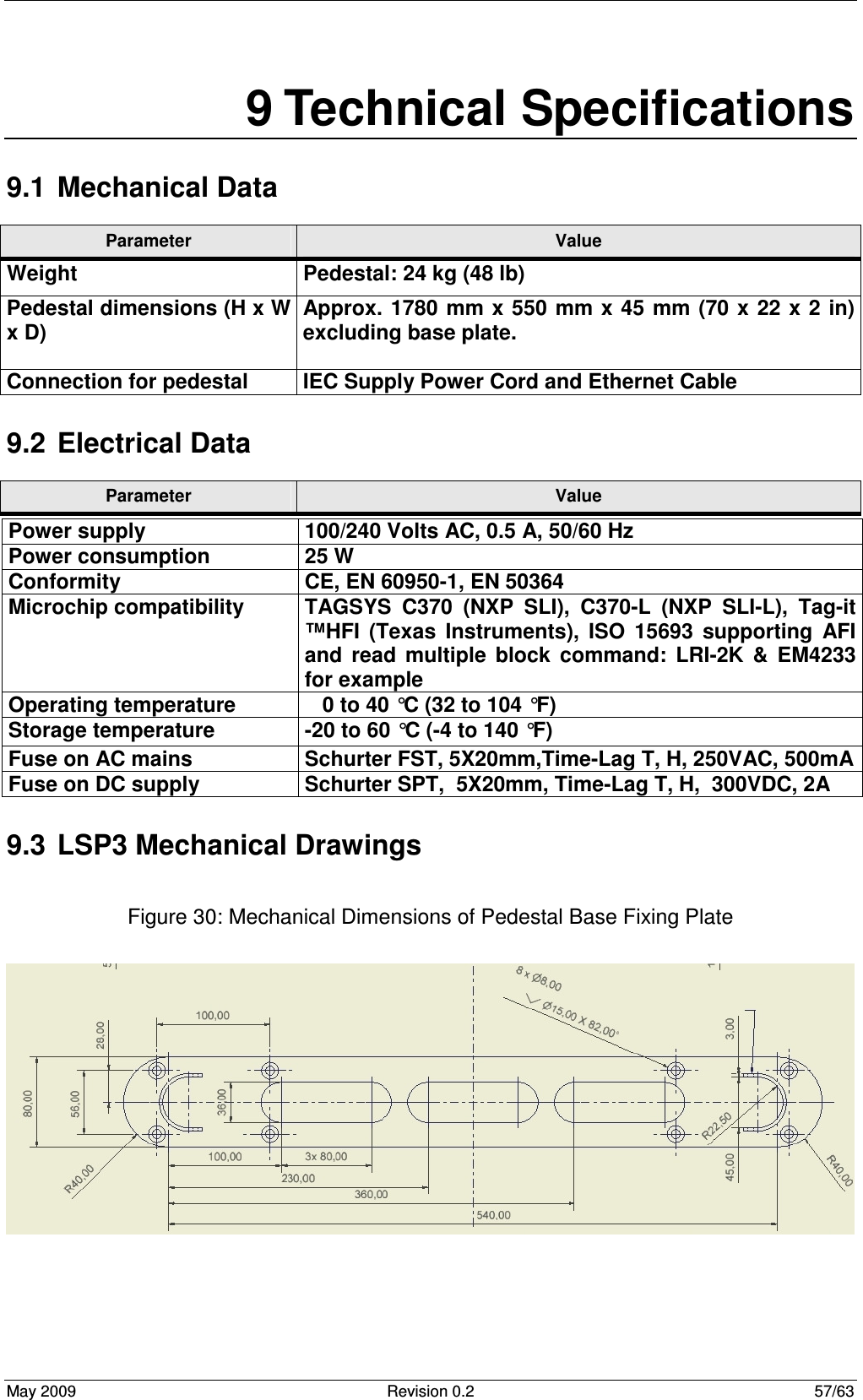
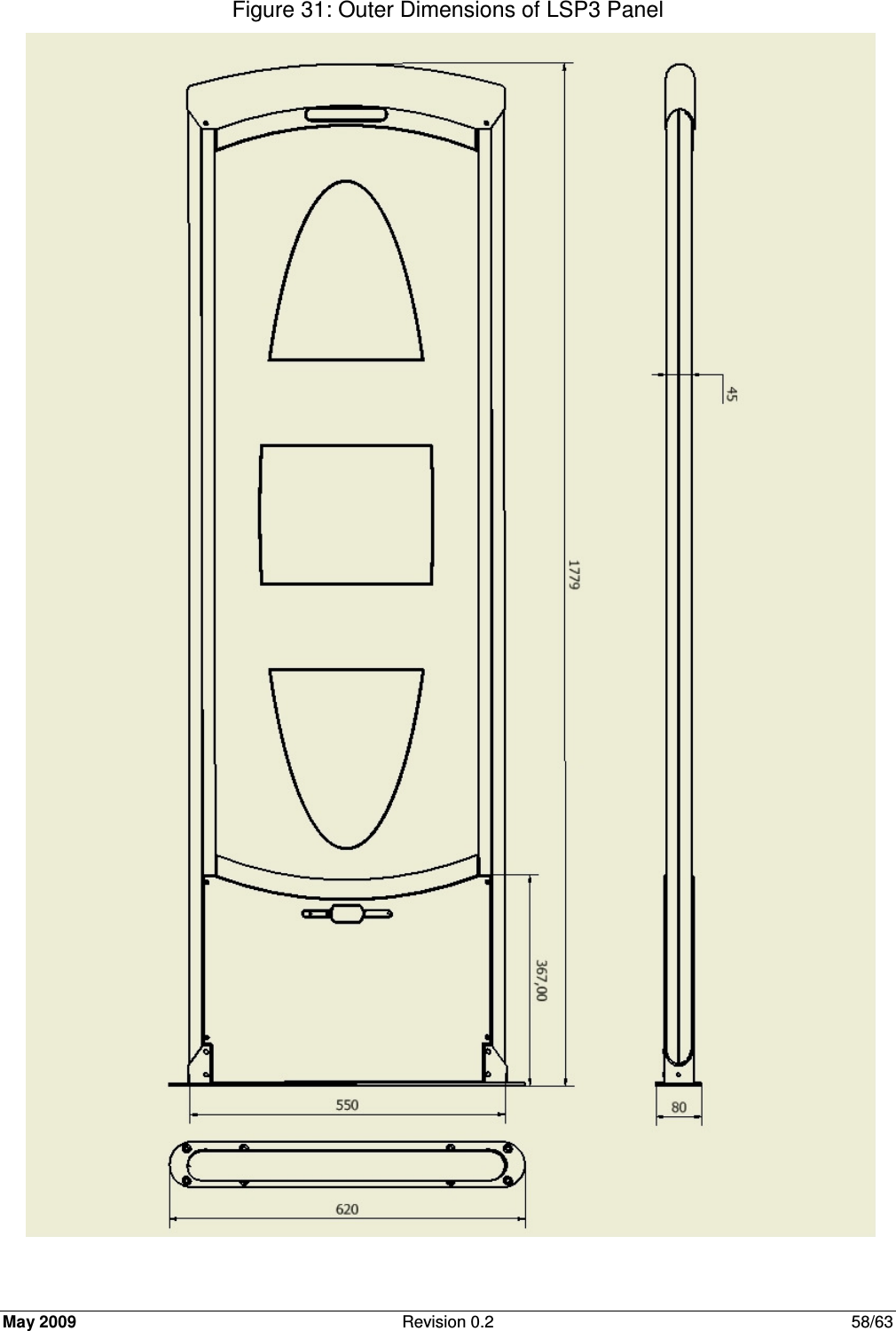
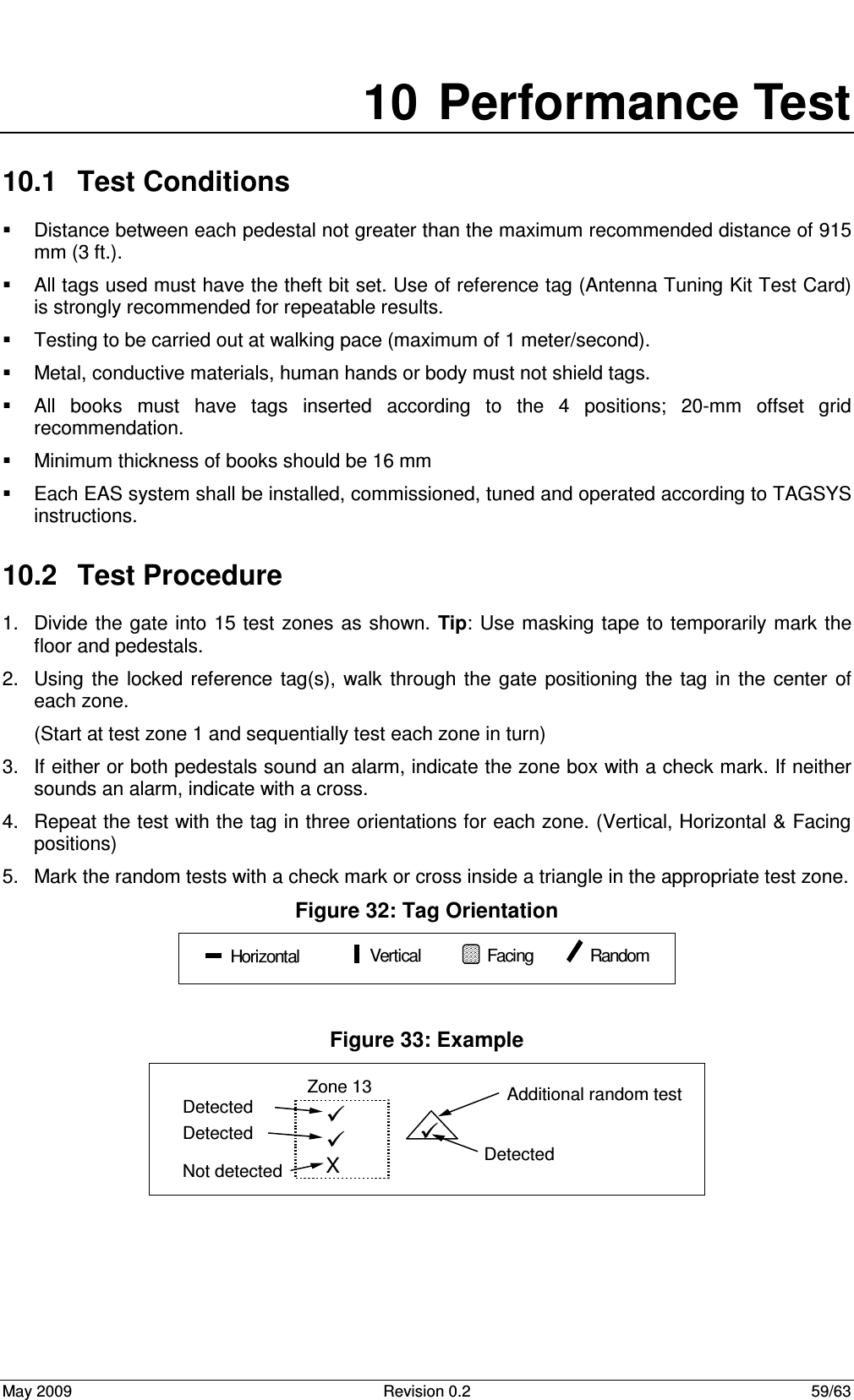
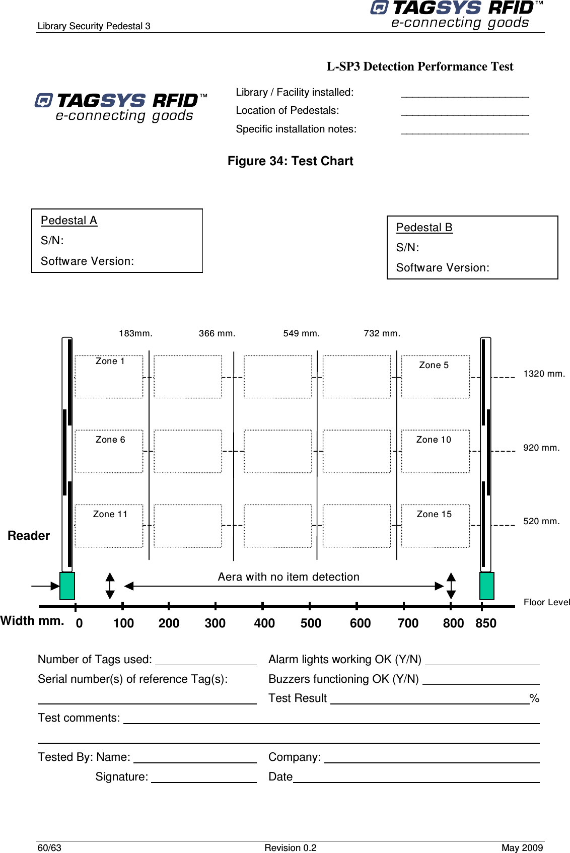
LSP3STANDARD User Manual
Manual
Navigation menu
Upload a User Manual
Namespaces
Wiki Guide
HTML
PDF
Info
Views
User Manual
Discussion / Help
Navigation