Tagsys MEDIOL40 RFID TAG READER User Manual Manual
Tagsys S.A. RFID TAG READER Manual
UserManual.wiki
>
Tagsys
>
MEDIOL40 User Manual
>
Manual.pdf
Contents
1.
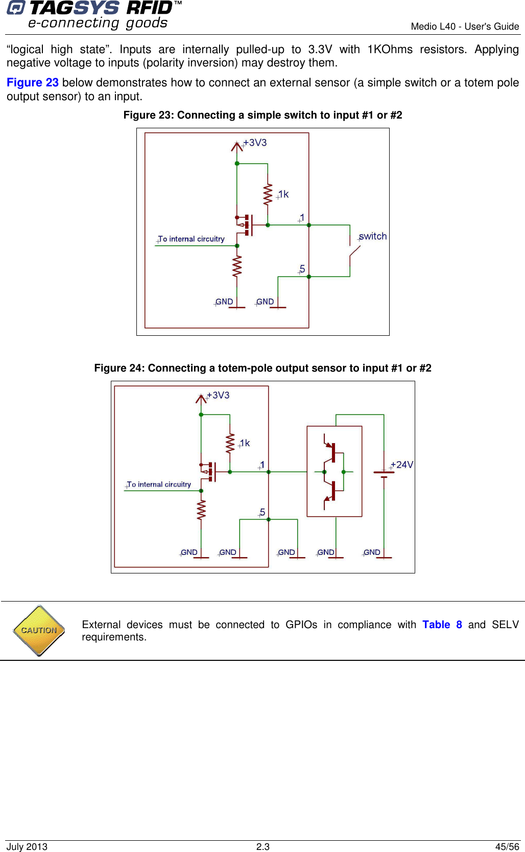
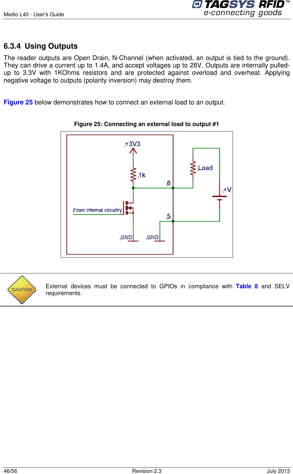
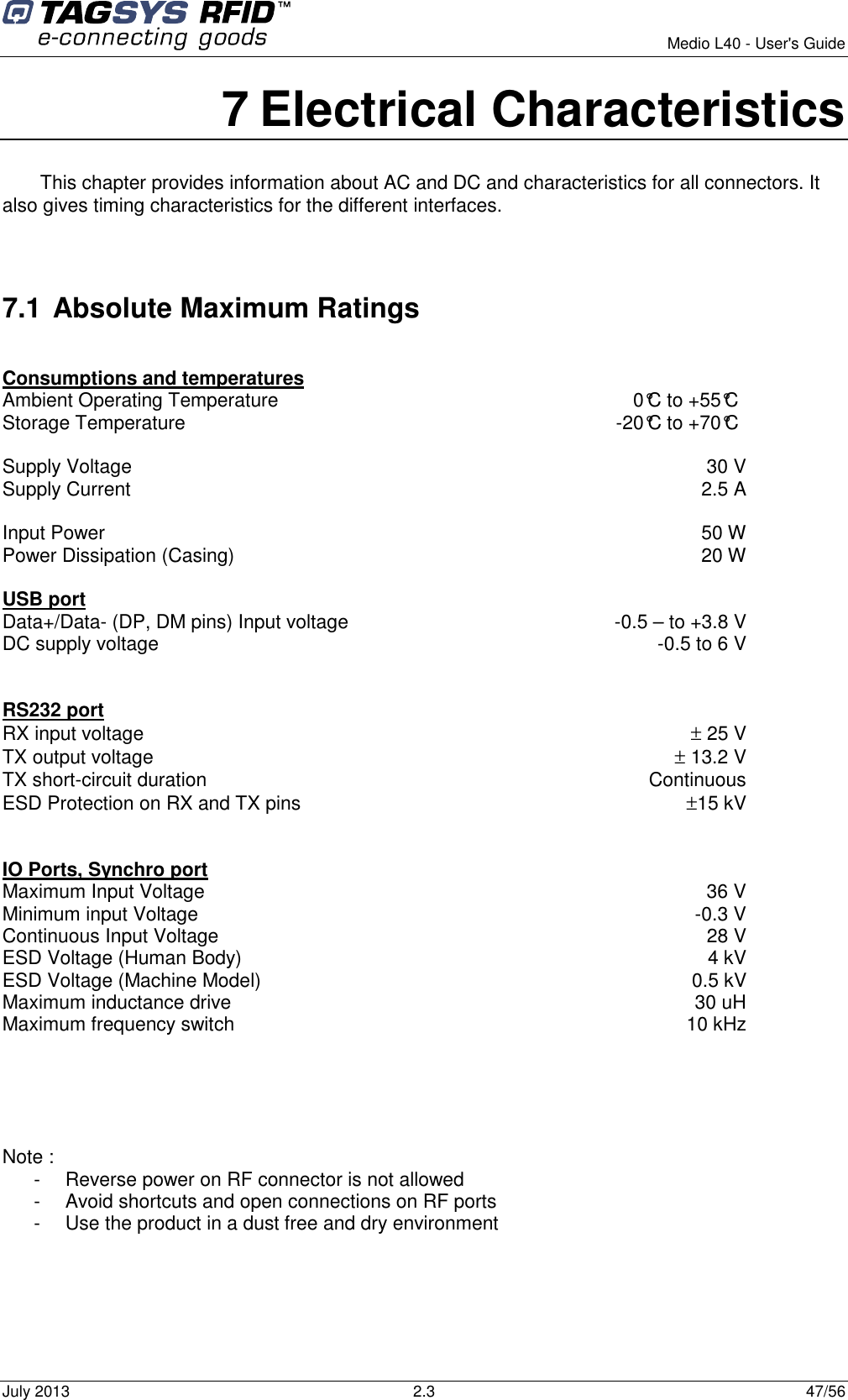
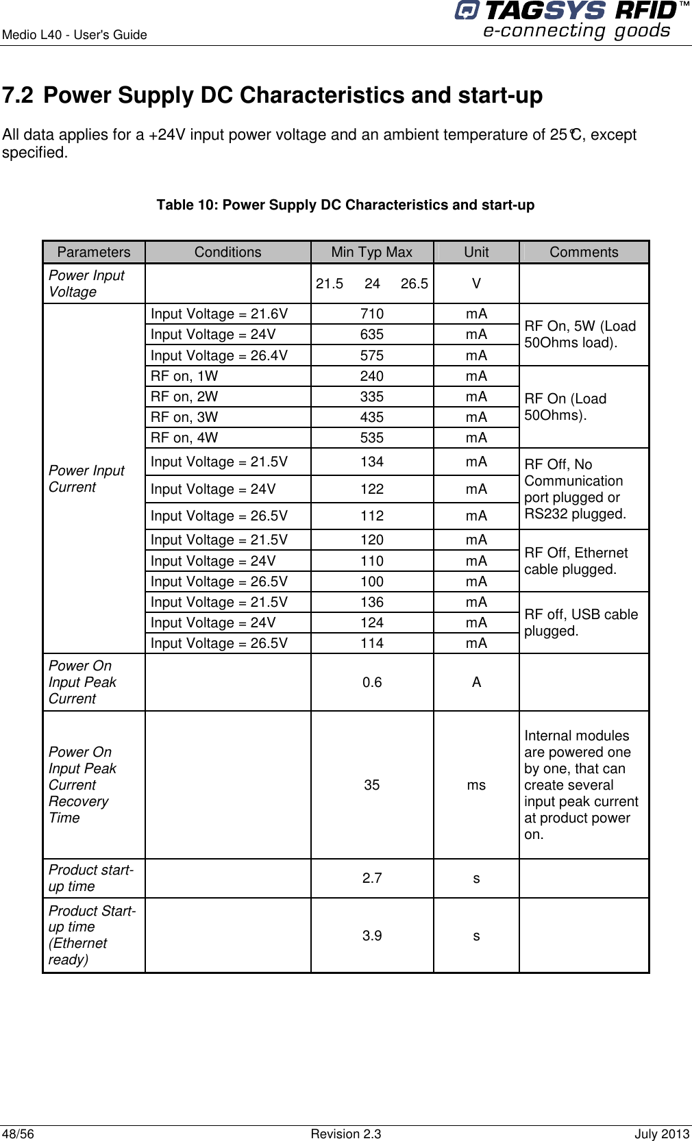
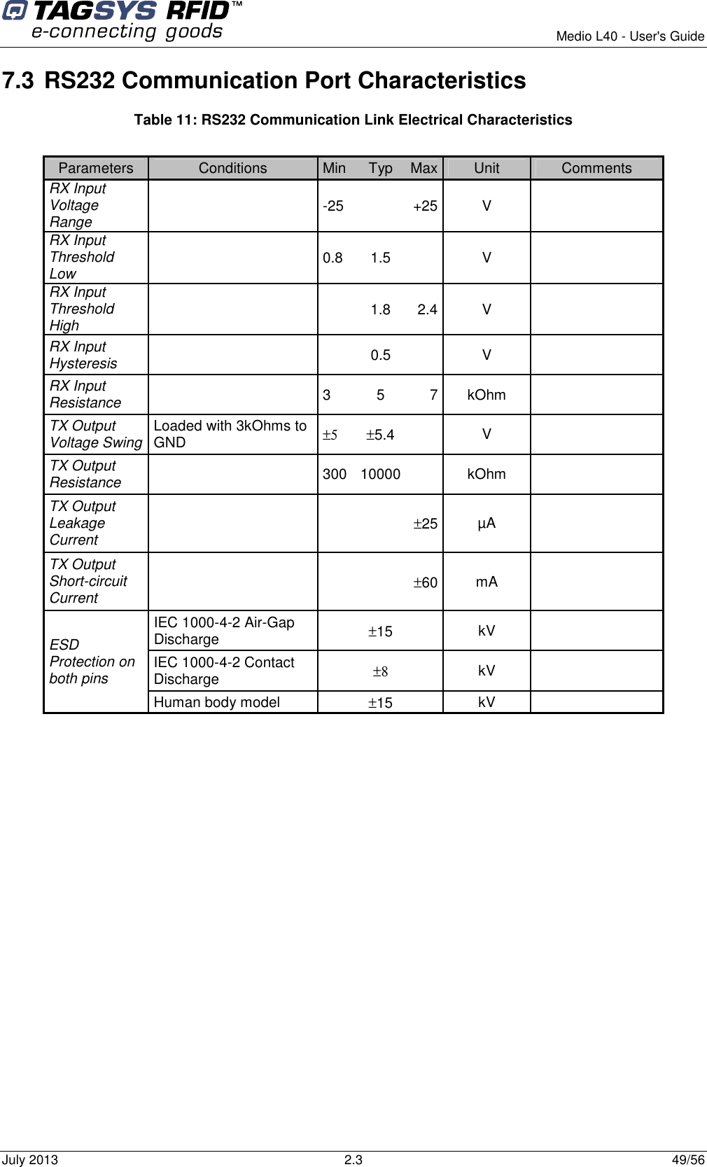
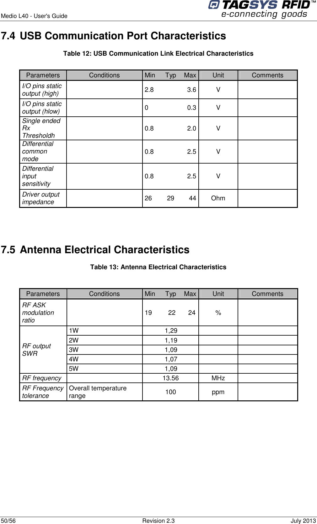
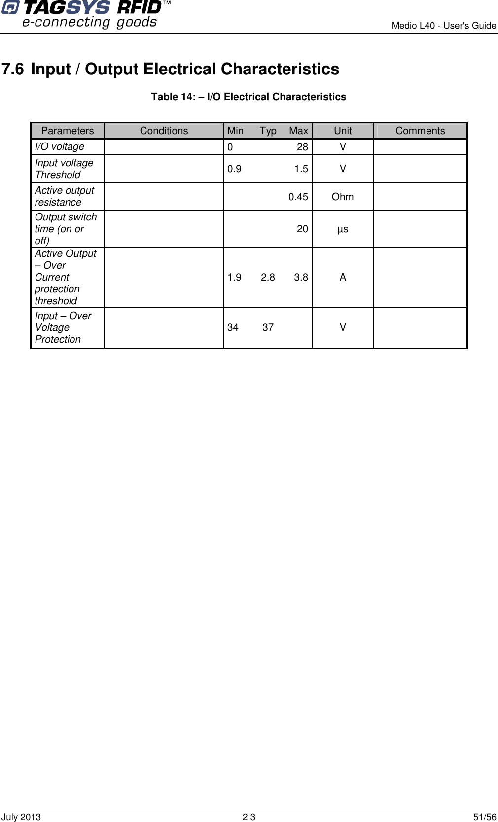
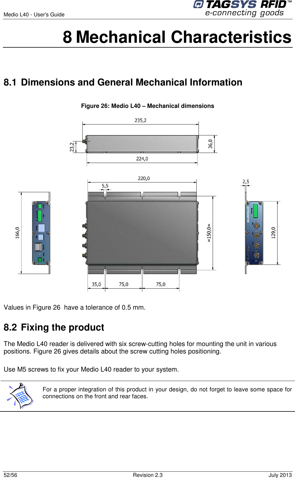
Manual
2.
Manual.pdf
Manual.pdf
Navigation menu
Upload a User Manual
Namespaces
Wiki Guide
HTML
PDF
Info
Views
User Manual
Discussion / Help
Navigation