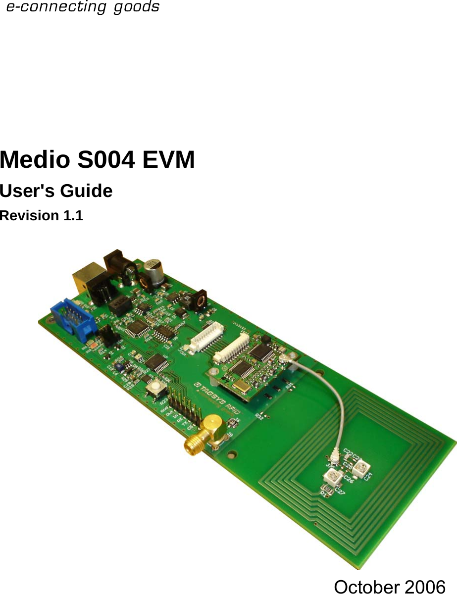
Tagsys MEDIOS004EVAL Medio S004 EVM Evaluation Board User Manual Medio S004 EVM

Tagsys S.A. Medio S004 EVM Evaluation Board Medio S004 EVM

Manual

        Medio S004 EVM User's Guide Revision 1.1   October 2006
  Medio S004 EVM Publishing Information Disclaimer and Limitation of Liability All information herein is either public information or is the property of and owned solely by TAGSYS who shall have and keep the sole right to file patent applications or any other kind of intellectual property protection in connection with such information. Nothing herein shall be construed as implying or granting to you any rights, by license, grant or otherwise, under any intellectual and/or industrial property rights of or concerning any of TAGSYS’ information. This document can be used for informational, non-commercial, internal and personal use only provided that:    the copyright notice below, the confidentiality and proprietary legend and this full warning notice appear in all copies.   this document shall not be posted on any network computer or broadcast in any media and no modification of any part of this document shall be made. Use for any other purpose is expressly prohibited and may result in severe civil and criminal liabilities. The information contained in this document is provided “AS IS” without any warranty of any kind. Unless otherwise expressly agreed in writing, TAGSYS makes no warranty as to the value or accuracy of information contained herein. The document could include technical inaccuracies or typographical errors. Changes are periodically added to the information herein. Furthermore, TAGSYS reserves the right to make any change or improvement in the specifications data, information, and the like described herein, at any time. Therefore TAGSYS assumes no liability and is not responsible for customer applications or product or software which include TAGSYS products. TAGSYS HEREBY DISCLAIMS ALL WARRANTIES AND CONDITIONS WITH REGARD TO THE INFORMATION CONTAINED HEREIN, INCLUDING ALL IMPLIED WARRANTIES OF MERCHANTABILITY, FITNESS FOR A PARTICULAR PURPOSE, TITLE AND NON-INFRINGEMENT. IN NO EVENT SHALL TAGSYS BE LIABLE, WHETHER IN CONTRACT, TORT OR OTHERWISE, FOR ANY INDIRECT, SPECIAL OR CONSEQUENTIAL DAMAGES OR ANY DAMAGES WHATSOEVER INCLUDING BUT NOT LIMITED TO DAMAGES RESULTING FROM LOSS OF USE, DATA, PROFITS, REVENUES, OR CUSTOMERS, ARISING OUT OF OR IN CONNECTION WITH THE USE OR PERFORMANCE OF INFORMATION CONTAINED IN THIS DOCUMENT. TAGSYS does not and shall not warrant that this product/system/equipment will be resistant to all possible attacks, and shall not incur, and disclaims, any liability in this respect. Even if each product is compliant with current security standards in force on the date of their design, security mechanisms' resistance necessarily evolves according to the state-of-the-art in security and notably under the emergence of new attacks. Under no circumstances shall TAGSYS be held liable for any third party actions, and in particular in case of any successful attack against systems or equipment incorporating TAGSYS products. TAGSYS disclaims any liability with respect to security for direct, indirect, incidental or consequential damages that result from any use of its products. It is further stressed that independent testing and verification by the person using the product is particularly encouraged, especially in any application in which defective, incorrect, or insecure functioning could result in damage to persons or property, denial of service, or loss of privacy. Pictures in this document are not representative of the final product. In particular, connectors’ availability is subject to local radio regulations. All the pictures are related to European product.  © 2000-2006 TAGSYS. All rights reserved. Microsoft, Visual C++, Windows, and Windows NT are either registered trademarks or trademarks of Microsoft Corporation in the U.S.A. and/or other countries. I-Code is a registered trademark of Philips. Tag-It is a registered trademark of Texas Instruments.  Printed in France. TAGSYS – 180 Chemin de St Lambert, 13821 LA PENNE SUR HUVEAUNE, France. Tel: +33 (0)4.91.27.57.00 / Fax: +33 (0)4.91.27.57.01 Document Reference: 12125A1 2/33  Revision 1.1   October 2006
     Medio S004 EVM Read This First Welcome to the TAGSYS range of products operating at the 13.56 MHz frequency. This range of products is used to implement high-quality RFID systems for demanding applications. This document provides information about how to install and use the Medio S004 EVM (Evaluation Module).  Audience This document requires familiarity with RFID technology. It is intended for people in charge of installing and using the product. Conventions Symbol Meaning  CAUTION: A note that advises users that a specific action could result in the loss of data or damage the hardware. WARNING: A note that advises users that a specific action may result in physical harm.   A note that provides additional information that helps the user perform a task or obtain the best performance from the product.  If you need assistance Please contact your nearest TAGSYS sales representative or the TAGSYS welcome desk at: Telephone:  +33 (0)4 91 27 57 00  Fax:  +33 (0)4 91 27 57 01 E-Mail:  info@tagsysrfid.comWebsite:  http://www.tagsysrfid.comContact for Comments We welcome your feedback to help us provide high quality documentation.  For technical comments, please contact our welcome desk: Telephone:  +33 (0)4 91 27 57 00  Fax:  +33 (0)4 91 27 57 01 E-Mail:  info@tagsysrfid.comPlease remember to quote the Document Reference Number 12125A1, your job title and your company.  October 2006  Revision 1.1  3/33
  Medio S004 EVM Quality Issues TAGSYS implements stringent quality controls at all stages of its manufacturing process. However, should you find a defect with this product, please notify your TAGSYS Quality Service representative using the dedicated Product Return Form. Telephone:    +33 (0)4 91 27 57 36 Fax:      +33 (0)4 91 27 57 02 4/33  Revision 1.1   October 2006
     Medio S004 EVM Table of Contents PUBLISHING INFORMATION __________________________________________________________ 2 DISCLAIMER AND LIMITATION OF LIABILITY__________________________________________________ 2 READ THIS FIRST ____________________________________________________________________ 3 AUDIENCE ____________________________________________________________________________ 3 CONVENTIONS _________________________________________________________________________ 3 IF YOU NEED ASSISTANCE________________________________________________________________ 3 CONTACT FOR COMMENTS _______________________________________________________________ 3 QUALITY ISSUES _______________________________________________________________________ 4 1 FOR YOUR SAFETY _______________________________________________________________ 7 1.1 GENERAL USE ____________________________________________________________________ 7 1.2 CARE AND MAINTENANCE ___________________________________________________________ 7 1.3 IMPORTANT SAFETY INFORMATION____________________________________________________ 8 1.3.1 OPERATING ENVIRONMENT ________________________________________________________ 8 2 CERTIFICATION___________________________________________________________________ 9 2.1 OCCUPATIONAL HEALTH ____________________________________________________________ 9 2.2 REGULATORY NOTICES _____________________________________________________________ 9 2.2.1 IN EUROPE (CE AND RTTE DIRECTIVES)_____________________________________________ 9 2.2.2 IN USA (FCC DIRECTIVE)_________________________________________________________ 10 2.2.3 IN CANADA _____________________________________________________________________ 10 2.3 ROHS AND WEEE DIRECTIVES _____________________________________________________ 11 2.3.1 ROHS (RESTRICTION OF THE USES OF CERTAIN HAZARDOUS SUBSTANCES)_______________ 11 2.3.2 WEEE (WASTE ELECTRICAL AND ELECTRONIC EQUIPMENT)____________________________ 11 3 INTRODUCTION__________________________________________________________________ 12 3.1 EVM DESCRIPTION _______________________________________________________________ 12 3.2 MEDIO S004 READER DESCRIPTION _________________________________________________ 12 3.3 MEDIO S004 EVM DELIVERY _______________________________________________________ 13 3.4 MEDIO S004 EVM KEY FEATURES___________________________________________________ 13 4 GETTING STARTED WITH THE EVM _______________________________________________ 16 4.1 INSTALLING THE EVM PRODUCT_____________________________________________________ 16 4.2 INSTALLING EVM DRIVERS _________________________________________________________ 16 4.2.1 WINDOW 98® USB DRIVERS INSTALLATION __________________________________________ 17 4.2.2 WINDOWS XP USB DRIVERS INSTALLATION __________________________________________ 17 5 TECHNICAL INFORMATION ON THE EVM __________________________________________ 19 5.1 MONITORING MEDIO S004 EVM DIGITAL SIGNALS______________________________________ 19 October 2006  Revision 1.1  5/33
  Medio S004 EVM 5.2 A-VSA ANTENNA DESCRIPTION _____________________________________________________ 20 5.3 PLUGGING ANOTHER ANTENNA TO THE SMA CONNECTOR _______________________________ 21 6 S004 EXPLORER _________________________________________________________________ 22 6.1 INSTALLING S004 EXPLORER _______________________________________________________ 22 6.2 RUNNING S004 EXPLORER _________________________________________________________ 24 6.2.1 USB COMMUNICATION ___________________________________________________________ 24 6.3 READING AND WRITING A TAG ______________________________________________________ 25 7 STAND-ALONE MODE ____________________________________________________________ 26 7.1 STAND-ALONE MODE FEATURES ____________________________________________________ 26 7.1.1 CUSTOMIZED ASCII MESSAGE FORMAT _____________________________________________ 27 7.1.2 REPETITION OPTION _____________________________________________________________ 27 7.1.3 TRIGGER INPUT _________________________________________________________________ 28 7.1.4 OUTPUT SETTINGS ______________________________________________________________ 28 7.2 STAND-ALONE MODE SETTINGS _____________________________________________________ 29 7.2.1 USING S004 EXPLORER __________________________________________________________ 29 7.3 DISABLING STAND-ALONE MODE ____________________________________________________ 30 8 WARRANTY CONDITIONS ________________________________________________________ 31 8.1 WARRANTY ______________________________________________________________________ 31 8.2 WARRANTY EXCLUSIONS __________________________________________________________ 31 8.2.1 GENERAL PROVISIONS ___________________________________________________________ 32 8.2.2 HOW TO RETURN DEFECTIVE PRODUCTS ____________________________________________ 32     6/33  Revision 1.1   October 2006
     Medio S004 EVM 1 For Your Safety 1.1 General Use The Medio S004 reader and EVM are designed to be reliable and to provide years of trouble-free service. Please observe the following general tips:   Take care not to damage the components. When working with the device, use only equipment that meet TAGSYS specifications.    This device is not waterproof and should not be exposed to moisture.    Protect the device from extreme temperatures. For example, do not place the device in a windowed area where the sun may cause extreme temperatures, and keep it away from heaters and other heat sources.   Do not store or use the device in any location that is extremely dusty, damp, or wet.  1.2 Care and Maintenance This device is a product of superior design and should be handled with care. The suggestions below will further increase the lifetime of this device.    Keep the device and all parts and accessories out of the reach of small children.   Keep the device dry. Precipitation, humidity and liquids contain minerals that will corrode electronic circuits.   Do not use or store the device in dusty, dirty areas. Its moving parts can be damaged.   Do not store in hot areas. High temperatures can shorten the life of electronic devices, damage batteries and warp or melt certain plastics.   Do not store in cold areas. When the device warms up (to its normal temperature), moisture can form which may damage electronic circuit boards.   Do not attempt to modify the device. Non-professional handling of the device may damage it.   Handle the device with care. Shocks may break internal circuit boards.   If the device or any accessory are not working properly, take it to your nearest qualified TAGSYS representative. October 2006  Revision 1.1  7/33
  Medio S004 EVM 1.3 Important Safety Information 1.3.1 Operating Environment When connecting the device or any accessory to another device, read its user’s guide for detailed safety instructions. Do not connect incompatible products. 8/33  Revision 1.1   October 2006
     Medio S004 EVM 2 Certification 2.1 Occupational Health  TAGSYS EVM has been designed and tested to be in conformity with the European Standard EN 50364 “Limitation of human exposure to electromagnetic fields from devices used in Electronic Article Surveillance (EAS), Radio Frequency Identification (RFID) and similar applications” in conjunction with the European Standard EN 50357 describing how to evaluate the exposure level. The EVM has been also designed to be in conformity with Specific Absorption Rate (SAR) standards according to FCC CFR47 and EN 50392:2004 recommendations.  Modification of any part of TAGSYS System is prohibited without the written consent of  TAGSYS. Unauthorized modifications may void the certificate of conformity of the equipment and will also void the TAGSYS certificate of warranty. 2.2 Regulatory Notices An RFID system typically composed of an RF emission device connected to an antenna such as the Medio S004 EVM comprising the Medio S004 reader and the EVM with its embedded antenna. Every RFID system is subject to national regulations that may differ by country. The EVM is meant to be used solely for evaluation purposes. It is the responsibility of the system integrator to ensure that the final solution meets all regulatory requirements.    The Medio S004 EVM product is primary intended for evaluation usage and as such is not supposed to be integrated. Nevertheless it is the responsibility of the CIT (Certified Integrators by TAGSYS) to integrate the Medio S004 EVM as described in this Integrator’s Guide. If the Medio S004 EVM is integrated in custom solution, it is the sole responsibility of the manufacturer to obtain the required approvals for the customized product. 2.2.1  In Europe (CE and RTTE Directives)  The Medio S004 EVM complies (CE Declaration of Conformity granted) with the European EMC directive. The Medio S004 EVM complies with the requirements of the Telecommunication Terminal Equipment Act (FTEG) and the RTTE Directive 1995/5/EC. October 2006  Revision 1.1  9/33
  Medio S004 EVM  2.2.2  In USA (FCC Directive) Medio S004 EVM WARNING TO USERS IN THE UNITED STATES FEDERAL COMMUNICATIONS COMMISSION (FCC) RADIO INTERFERENCE STATEMENT 47 CFR Section 15.105(b)  This equipment has been tested and found to comply with the limits for a Class B digital device, pursuant to Part 15 of the FCC Rules. These limits are designed to provide reasonable protection against harmful interference in a residential installation. This equipment generates uses and can radiate radio frequency energy and if not installed and used in accordance with the instructions may cause harmful interference to radio communications. However, there is no guarantee that interference will not occur in a particular installation. If this equipment does cause harmful interference to radio or television reception, which can be determined by turning the equipment off and on, the user is encouraged to try to correct the interference by one or more of the following measures:  ▪   Reorient or relocate the receiving antenna. ▪   Increase the separation between the equipment and receiver. ▪   Connect the equipment into an outlet on a circuit different to that to which the receiver is connected. ▪   Consult the dealer or an experienced radio/TV technician for help. NO UNAUTHORIZED MODIFICATIONS 47 CFR Section 15.21 CAUTION: This equipment may not be modified, altered, or changed in any way without signed written permission from TAGSYS SA. Unauthorized modification may void the equipment authorization from the FCC and will void the TAGSYS warranty.  ANTENNA REQUIREMENT 47 CFR Section 15.203 CAUTION: This equipment must be professionally installed. The installer shall be responsible for ensuring that only the supplied antenna is employed so that the limits in this part are not exceeded. Non-professional installation or installation of the equipment with an improper antenna may void the equipment authorization from the FCC and will void the TAGSYS warranty. The Medio S004 EVM has been designed to comply with FCC 47 CFR Part 15 Rules. Operation is subject to the following two conditions: (1) The system devices may not cause harmful interference, and (2) The library system devices must accept any interference received, including interference that may cause undesired operation. 2.2.3 In Canada Cet appareil numérique de la classe B respecte toutes les exigences du Règlement sur le matériel brouilleur du Canada. This Class B digital apparatus meets all requirements of the Canadian Interference-Causing Equipment Regulations 10/33  Revision 1.1   October 2006
     Medio S004 EVM 2.3  RoHS and WEEE Directives 2.3.1  RoHS (Restriction of the uses of certain Hazardous Substances) TAGSYS certifies that this product is compliant with the European Directive 2002/95/EC for the restriction in Electric and Electronic Equipments (RoHS) of the use of the following hazardous substances: • Lead • Mercury • Cadmium • Hexavalent Chromium •  Polybrominated biphenyl flame retardants •  Polybrominated diphenyl ether flame retardants  This declaration is based on information provided by our suppliers and subcontractors.  2.3.2 WEEE (Waste Electrical and Electronic Equipment)   This product bears the selective sorting symbol for waste electrical and electronic equipment (WEEE) This means that this product must be handled pursuant to European Directive 2002/96/EC in order to be recycled or dismantled to minimize its impact on the environment. For further information, please contact your local or regional authorities.   October 2006  Revision 1.1  11/33
  Medio S004 EVM 3 Introduction 3.1 EVM Description The Evaluation Module (EVM) provided by Tagsys allows the OEM to test the reader before its integration within their solution: • The EVM provides all necessary connections to perform tests and includes also an embedded antenna. • The EVM is not meant to be integrated within a final solution; it is only intended to test the performance of the Medio S004 reader. • The EVM is supplied with a foot print pattern that can be used to solder the Medio S004 reader to it.  3.2 Medio S004 Reader Description TAGSYS Medio S004 reader is dedicated to Original Equipment Manufacturer (OEM) applications. The Medio S004 reader is a Universal Short Range RFID reader designed to operate at 13.56 MHz with any I-CodeTM EPC, I-CodeTM UID, I-CodeTM 1, and ISO 15693 compliant tags.  The Medio S004 reader’s technical features make it the ideal device for easy integration into handheld computers and printers. It offers the following features on a small printed circuit board: • A high-performance radio processing unit operating at 13.56 MHz, • A digital processing unit that incorporates chip drivers and the anti-collision feature depending on the type of chip. • The Medio S004 reader is provided with solder pads to help its soldering fixation to the EVM. Medio S004 EVM requires minimal computing power (host workstation) and communicates at high speed, thanks to the TAGSYS enhanced communication protocol (STX-E) already used for the Medio P101 series and the Medio L100/L200 readers. The Medio S004 reader is fixed onto the EVM with help of screws and is electrically connected to the EVM using the 10 pin Molex cable.   In case you were to solder the Medio S004 reader to the EVM, do not use the Molex Cable connector.  12/33  Revision 1.1   October 2006
     Medio S004 EVM 3.3 Medio S004 EVM Delivery The Medio S004 EVM reader kit is supplied with the following items: Table 1: Package Contents Quantity  Item 1  Medio S004 reader mounted onto the EVM 1 CD-ROM including: •  Medio S004 Integrator's Guide •  Medio S004 Command Set •  User-friendly Sx Explorer software provided for test and debug operations on Windows® 9x, NT®, 2000 and XP platforms •  Medio STX Windows® DLLs to facilitate the development your own applications on Windows® Mobile platform •  Medio STX Windows® DLL Programming Guide •  One set of Microsoft® Visual C++® source code and executable samples using the Medio STX Windows® DLLs 1  Welcome Letter / Product Return Form  3.4 Medio S004 EVM Key Features Table 2: Medio S004 EVM Key Features Description  Medio S004 Operating Frequency  13.56 MHz Chip Compatibility  ISO 15693 compliant  I-Code EPCTM I-Code UIDTM C270  (Philips I-CodeTM-1) Serial Link  Asynchronous serial TTL (RS-232 compliant) or 3-wired Synchronous I/O  1 input 1 Output   October 2006  Revision 1.1  13/33
  Medio S004 EVM      Figure 1: Medio S004 TAGSYS RFID Tag Reader and EVM Module    Molex Cable Power Supply Connector USB Connector Medio S004 reader Output LED MCB coaxial Cable  A-VSA Antenna    USB RX/TX LED SMA Connector Com. Mode LED  Serial Selector  Push button for Input Monitoring Connector 14/33  Revision 1.1   October 2006
     Medio S004 EVM      Table 3: Component Descriptions Connector/Component  Description Medio S004  RFID Reader Power Supply Connector  To plug the power supply to the EVM power connector. USB Connector  To connect the USB cable and the other end to the host PC. RX and TX USB LED  RX led flashes orange when the host is sending commands to the EVM TX led flashes green when the reader is sending data to the host Serial Selector This jumper selects the Synchronous / Asynchronous mode.  Synchronous Mode    Asynchronous Mode The jumper must be positioned before plugging in the power and USB cables. To change the serial communication mode, you must unplug the power and USB cables, change the jumper setting, and reconnect the power and USB cables. The green communication mode LED is on when synchronous serial mode is selected.  Push Button for input  When pushed provides +5V on the IN pin. Output LED  This LED is ON (yellow) when +5V is present on the OUT pin. Molex Cable  To connect the reader signals from the EVM to the S004 reader. MCB Coaxial Cable  To connect the reader to its antenna Monitoring Connector  This is used solely for monitoring the reader signals. See the Medio S004 Integrator’s Guide for more information. SMA Connector External Antenna connector can be used to connect other antennas. (Be sure to connect the antenna cable from the S004 RF coaxial connector to the coaxial that is next to the SMA connector.)  Carefully unplug the RF Coaxial cable for the EVM antenna and connect it to the SMA antenna receptacle near the SMA connector.  A-VSA  The built-in antenna has a RF coaxial connector which (when used) must be connected to the S004 RF coaxial connector.       October 2006  Revision 1.1  15/33
  Medio S004 EVM 4 Getting Started with the EVM  4.1 Installing the EVM product  1.  Before any plugging takes place, please select the communication mode using the serial selector.   Asynchronous serial mode  Synchronous serial mode   2.  Plug both power supply and USB supply cables to the EVM. If the Synchronous serial communication is selected, the green LED for Serial Communication mode turns on.   DO NOT change the Serial Communication Selector until both power supply and USB cable are unplugged or unpredictable result can occur.  4.2 Installing EVM drivers At first connection to the PC USB port, Windows® will detect the TAGSYS Evaluation Board (for Medio S004 reader) and will ask you for driver installation. USB drivers are located into the USB Drivers folder on the product CD-Rom. Two drivers must be installed: 16/33  Revision 1.1   October 2006
     Medio S004 EVM -  The first one is the direct driver, which provides direct access to USB device via a dynamic link library (DLL). -  The second one is the virtual COM port (VCP) driver. The VCP driver emulates a standard PC COM port. 4.2.1 Window 98® USB Drivers Installation Power up and connect your Medio S004 to a spare USB port on your PC. This should bring up a “Building Driver Information Database” followed by the Windows Add New Hardware Wizard. Click “Next” to proceed with the installation   Select “Search for the best driver for your device” and then click “Next”   Select “Specify a location” and click the Browse button to select the USB Drivers folder on the Product CR-Rom. Once the files have been located, click “Next” to proceed with the installation   Click “Next” to install the device   Windows® should then display a message indicating that the installation was successful. Click “Finish” to complete the installation. To confirm that the installation has completed successfully, open the Device Manager and select “View devices by type”. The TAGSYS Medio S004 appears as a USB device connected to a USB port The next step is to install the VCP drivers. Power up and connect your Medio S004 to a spare USB port on your PC. This should bring up a “Building Driver Information Database” followed by the Windows Add New Hardware Wizard.   Select “Search for the best driver for your device” and then click “Next”   Select “Specify a location” and click the Browse button to select the USB Drivers folder on the Product CR-Rom. Once the files have been located, click “Next” to proceed with the installation    Click “Next” to install the device   Windows® should then display a message that the installation of the serial converter driver was successful. The COM port emulation driver must now be installed. Click “Finish” to complete the installation. To confirm that the installation has completed successfully, open the Device Manager and select “View > devices by type”. The TAGSYS Medio S004 appears as an additional COM port. 4.2.2  Windows XP USB Drivers Installation Power up and connect your Medio S004 to a spare USB port on your PC. This will launch the Windows Found New hardware Wizard   Select “No, not this time” and click next to proceed with the installation   Select “Install from a list or specific location (Advanced)” and then click “Next”   Select “Search for the best driver in these locations” and click the Browse button to select the TAGSYS USB Drivers folder on the Product CR-Rom. Then click “Next” to proceed.   Windows should then display a message indicating that the installation was successful. Click Finish to complete the installation To confirm that the installation has completed successfully, open the Device Manager and select “View > Devices by type”. The TAGSYS Medio S004 appears as a USB device connected to a USB port. October 2006  Revision 1.1  17/33
  Medio S004 EVM The next step is to install the VCP drivers. Power up and connect your Medio S004 to a spare USB port on your PC. This will launch the Windows Found New Hardware Wizard   Select “No, not this time” and click next to proceed with the installation   Select “Install from a list or specific location (Advanced)” and then click “Next”   Select “Search for the best driver in these locations” and click the Browse button to select the USB Drivers folder on the Product CR-Rom. Then click “Next” to proceed.   Windows should then display a message indicating that the installation was successful. Click Finish to complete the installation. This has installed the serial converter. The COM port emulation driver must be installed after this has completed.   After clicking “Finish”, the Found New Hardware Wizard will continue by installing the COM port emulation driver. To confirm that the installation has completed successfully, open the Device Manager and select “View > Devices by type”. The TAGSYS Medio S004 appears as an additional COM port.   18/33  Revision 1.1   October 2006
     Medio S004 EVM 5 Technical Information on the EVM We recommend you to first read the Medio S004 Integrator’s Guide for details on the Medio S004 reader. 5.1 Monitoring Medio S004 EVM Digital Signals Signals sent to the Medio S004 can be monitored connecting probes (oscilloscope) to the Monitoring Connector as described below: Figure 2: Monitoring Connector  Pin  Pin  Signal 1 GND 2 OUT 3 IN 4 RX 5 TX 6 CS 7 COMSELECT   DO NOT drive any signal with a digital level on this connector. The EVM may be damaged. October 2006  Revision 1.1  19/33
  Medio S004 EVM Example of an asynchronous communication (SetIO command – 115200 Bps)          Example of a synchronous communication (SetIO command)         5.2 A-VSA Antenna description The A-VSA is a 13.56MHz resonant antenna designed according to the following schematic:  RpCpCsL  Parameter  Value Nominal working frequency  13,560MHz Number of 0,2mm turns  6 Internal turn dimensions  22mmx37mm External turn dimension  39mmx54mm PCB inductance (L)  2400nH Damping Resistor (Rp)  15000 Ohm Parallel Capacitor (Cp)  ~39pF Serial Capacitor (Cs)  ~15pF Q factor  28   20/33  Revision 1.1   October 2006
     Medio S004 EVM 5.3 Plugging another antenna to the SMA connector Other antennas may be plugged to the Medio S004 EVM antenna output using a MCB coaxial cable. The SMA connector may also be used to convert the MCB connector to a standard one, and plug a SMA cable to another antenna. To do so, unplug the MCB cable from the A-VSA and connect it to the SMA connector as shown below:       Depending on your local radio regulations, you will have to solder a SMA connector on the dedicated footprint by yourself but this will void the TAGSYS certification.   Using another antenna will void any of the certifications (CE or FCC). You will have to certify your final integrated system according to local radio regulations. To help you certify your final integrated system, radio test report is included on the CDROM (“Medio S004 – Radio Test Reports” folder)     October 2006  Revision 1.1  21/33
  Medio S004 EVM 6 S004 Explorer The Medio S004 reader is delivered with the Sx Explorer software tool intended to easily setup the reader, test it and perform reading and writing operations according to the antenna and type of tag to be used. In addition, S004 Explorer can display additional information such as the Product Reference and Firmware version and revision. This section describes how to start with Sx Explorer. 6.1 Installing S004 Explorer To install S004 Explorer software, insert the product CD-ROM into the disk drive on your PC and run the Setup from the “Medio S004 - Software Suite\ Tools\S004 Explorer 1-0-1 folder and click “Next”    Click the “Browse” button to choose a specific installation folder. 22/33  Revision 1.1   October 2006
     Medio S004 EVM   Once the correct folder is selected, click “Next”    Click “Next” to start the installation process. A shortcut will be created on your desktop and a program group will be created in the start menu. October 2006  Revision 1.1  23/33
  Medio S004 EVM 6.2 Running S004 Explorer 6.2.1 USB Communication Before launching S004 Explorer, be sure which COM port number is assigned to the Tagsys EVM Module. Open the Device Manager and select “View > Devices by type”.   The COM port number is assigned to the Tagsys EVM Module.  Power up the Medio S004 EVM and connect the USB cable to both your PC and the Medio S004 EVM. Run Sx Explorer. If the following window is displayed click yes.    Open the Communication Settings window (CTRL+C) and check the type of the media, the COM port number and the communication speed. The default communication speed for the Medio S004 EVM is 115200 Baud.    Click OK. Now S004 Explorer is ready to communicate with your Medio S004 EVM.  24/33  Revision 1.1   October 2006
     Medio S004 EVM 6.3 Reading and Writing a Tag S004 Explorer includes a Wizard function used to guide you each step of how to read or program a tag. We recommend using the Wizard function for users who are not familiar with all S004 Explorer capabilities and features. Click on the Wizard icon (magic wand) to open the S004 Explorer Wizard dialog box.    Select the type of chip from the drop–down menu or place the tag on the antenna and click the “Detect “button to automatically detect the tag type. Select the desired operation (Read or Write) and then click OK. All the necessary windows to perform the desired action will be automatically displayed on the screen. For more details concerning S004 Explorer, select the info menu and click Help (CTRL+H) to display the S004 Explorer User’s Guide. October 2006  Revision 1.1  25/33
  Medio S004 EVM 7 Stand-alone Mode Stand-alone Mode is designed to use the reader without using any command set. While in Stand-alone mode, the reader only performs tag reading operations. The reader sends the tag ID to the Host System using ASCII protocol via the Reader-to-Host interface.  ASCII protocol is used in order to provide hexadecimal data that can be read by a variety of terminal programs (e.g. Microsoft® HyperTerminal). 7.1 Stand-alone Mode Features Table 4 lists the available Stand-alone mode features.  Table 4: Available Features in Stand-alone Mode  Features  Medio S004 Customized tag type reading compatibility  (depending on downloaded application firmware) ISO 15693 compliant  I-Code EPCTM I-Code UIDTM C270  (Philips I-CodeTM-1) Serial Communication Type  Asynchronous serial TTL (RS-232 compliant) or 3-wired Synchronous Repetition Option  Available Customized ASCII message format STX/ETX Characters Header String Chip Description String ID String (variable length) End of Message String Input Trigger  Available Output for active trigger information  Available Output for tag reading information  Available 26/33  Revision 1.1   October 2006
     Medio S004 EVM 7.1.1 Customized ASCII Message Format When a tag is read, its data are transmitted to the host in the form of an ASCII character frame.  Table 5: Customized ASCII Message Format (TAGSYS RFID Tag is read)  Start of Text Header String Chip Description String ID End of Message String End of Text Description  <STX> (0x02) “TAGSYS-“ (Default)  Chip name  <CR/LF> (Default) <ETX> (0x03) I-Code EPC  2 to 24 characters I-Code UID  2 to 16 characters C270 (Philips I-Code™-1)2 to 16 characters      ISO15693 2 to 16 characters   S004 Optional Optional Optional  Required  Optional Optional  Medio S004 reader can decode all chips in Stand-alone mode. Only the ID field is required in the return ASCII message. All other fields are optional. The ID field length is programmable; the default lengths are given in Table 6. Table 6: Default ID Field Lengths Chip Type  Default ID Field Length I-Code EPC  24 (Total memory) I-Code UID  10 (Memory area 1) C270 (Philips I-Code™) chip  16 (Block 0 and Block 1) ISO 15693 compliant  16 (UID) 7.1.2 Repetition Option The reader constantly attempts to read any chips present in the field. When a chip ID is detected, the reader can send the information to the host in one of 2 modes: 1.  In “Repeated Read” mode, the reader returns a chip’s ID to the host with each successful read operation. 2.  In “Read Once” mode, the reader only returns the ID of a chip if the previous read corresponds to a different chip, or if all reading attempts have failed 4 times (this feature makes it possible to detect a chip’s potential exit out of the field).   October 2006  Revision 1.1  27/33
  Medio S004 EVM 7.1.3 Trigger Input When the trigger capability is enabled, a trigger state is used to start and stop the RF scanning. The trigger is connected to the input of the reader. Depending on the reply settings of the trigger, the ASCII message can be sent during the trigger activity (Repeated Read mode and Read Once mode are available) or at the end of the trigger. In this last case, a message is always sent to the host system:   if a tag has been read, the message contains its ID,   if no tag has been read, the message contains a No Message string (that can be defined) as shown in Table 7.  Table 7: Customized ASCII Message Format (TAGSYS RFID Tag is not read)  Start of Text  Header String  No Tag Found String  End of Message String  End of Text Description  <STX> (0x02) “TAGSYS-“ (Default) “????????“ (Default) <CR/LF> (Default) <ETX> (0x03) Size  1 character 0 to 16 characters 0 to 16 characters 0 to 16 characters 1 character Status Optional  Optional Required  Optional  Optional 7.1.4 Output Settings The output of the reader can be used to monitor the trigger activity or the successful reads. 28/33  Revision 1.1   October 2006
     Medio S004 EVM  7.2 Stand-alone Mode Settings Stand-alone Mode can be set in one of two ways while the reader is in Normal Operating mode  •  Using the Sx Explorer software provided with the reader •  Using “Set Stand-alone Mode” command followed by a “Reset Reader” command. For more information, refer to the Medio S004 Command Set document. 7.2.1  Using S004 Explorer Run the S004 Explorer software. In the Settings menu, select General Reader Settings     Enable    Standalone mode at next power on October 2006  Revision 1.1  29/33
  Medio S004 EVM 7.3 Disabling Stand-alone Mode The Medio S004 can be reset in Standard mode in one of two ways as described below: •  Use the S004 Explorer software provided with the reader and click Yes when the following window is displayed  •  Send the 'S' character using a console interface (for example, HyperTerminal). •  Unplug both power supply and USB cable. Change the Serial Communication Selector to Synchronous mode. Plug both power supply and USB cables. Then revert to Asynchronous mode if necessary by unplugging both power supply and USB cables and changing the Serial Communication Selector again. 30/33  Revision 1.1   October 2006
     Medio S004 EVM 8 Warranty Conditions 8.1 Warranty TAGSYS warrants that this Product shall comply with the functional specifications set forth herein for a period of one year from the date of delivery to the Buyer. This warranty is valid for the original Buyer of the Product and is not assignable or transferable to any other party. TAGSYS cannot be responsible in any way for, and disclaims any liability in connection with the operation or performance of:   any product in which the Product is incorporated;   any equipment not supplied by TAGSYS which is attached to or used in connection with the Product; or   the Product with any equipment This warranty does only cover the Product to the exclusion of any such other equipment. Optimal operation and performance of the Product are obtained by using TAGSYS’ readers, by applying TAGSYS installation guidelines and by having your installation reviewed by a TAGSYS’ technical consultant. TAGSYS warranty does not cover the installation, maintenance or service of the Product and is strictly limited to the replacement of Products considered as defective by TAGSYS and returned according to the return procedure defined below; in such case, TAGSYS will, at TAGSYS’ option, either replace every defective Product by one new Product or refund the purchase price paid by Buyer to TAGSYS for the defective Product. 8.2 Warranty Exclusions   Defects or damages resulting from storage of the Product under conditions which do not comply with TAGSYS specifications or normal usage   Defects or damages resulting from use of the Product in abnormal conditions (abnormal conditions being defined as any conditions exceeding the ones stated in the product specifications).   Defects or damages from misuse, accident or neglect.   Defects from improper testing, operation, maintenance or installation.   Defects from alteration, modification except modifications or adjustments specifically described in this Product reference guide, adjustment or repair, or any attempt to do any of the foregoing, by anyone other than TAGSYS.   Any action on Product that prevents TAGSYS from performing an inspection and test of the Product in case of a warranty claim.   Tampering with or abuse of the Product.   Any use or incorporation by the Buyer or a third party of TAGSYS' Product into life saving or life support devices or systems, or any related products, TAGSYS expressly excludes any liability for such use. October 2006  Revision 1.1  31/33
  Medio S004 EVM 8.2.1 General Provisions This warranty sets forth the full extent of TAGSYS responsibility regarding the Product. In any event, TAGSYS warranty is strictly limited to (at TAGSYS’ sole option) the replacement or refund of the Products purchase price to TAGSYS, of Products considered as defective by TAGSYS. The remedy provided above is in lieu and to the exclusion of all other remedies, obligations or liabilities on the part of TAGSYS for damages, whether in contract, tort or otherwise, and including but not limited to, damages for any defects in the Products or for any injury, damage, or loss resulting from such defects or from any work done in connection therewith or for consequential loss, whether based upon lost goodwill, lost resale profits, impairment of other goods or arising from claims by third parties or otherwise. TAGSYS disclaims any explicit warranty not provided herein and any implied warranty, guaranty or representation as to performance, quality and absence of hidden defects, and any remedy for breach of contract, which but for this provision, might arise by implication, operation of law, custom of trade or course of dealing, including implied warranties of merchantability and fitness for a particular purpose. 8.2.2  How to Return Defective Products The Buyer shall notify TAGSYS of the defects within 15 working days after the defects are discovered. Defective Products must be returned to TAGSYS after assignment by a TAGSYS Quality Department representative of an RMA (Return Material Authorization) number. No Products shall be returned without their proof of purchase and without the acceptance number relating to the return procedure. All Products shall be returned with a report from the Buyer stating the complete details of the alleged defect. Call +33 4 91 27 57 36 for return authorization and shipping address. If returned Products prove to be non-defective, a charge will be applied to cover TAGSYS’ analysis cost and shipping costs. If the warranty does not apply for returned Products (due to age, or application of a warranty exclusion clause), a quote for replacement will be issued, and no replacement will be granted until a valid purchase order is received. If no purchase order is received within 30 days after the date of TAGSYS quote, TAGSYS will return the products and charge the analysis cost and shipping costs. All replaced Products shall become the property of TAGSYS. The Product Return Form is included on the following page. This form should accompany any product you need to return to TAGSYS for analysis in the event of a problem. 32/33  Revision 1.1   October 2006
     Medio S004 EVM  Product Return Form Customer Profile: Company: ................................................................  Address: ....................................................................................................................................................................................................................................  City & State:.............................................................  Zip Code: .................................................................  Country: ...................................................................    Contact Name: .......................................................  Contact e-mail:  ......................................................  Contact Phone: ......................................................  Contact Fax:...........................................................  Order identification:  Product Name:.........................................................  Order Number (OEF):..............................................     Invoice Number: .....................................................  Return Quantity:  ....................................................  Reason for return: ......................................................................................................................................................................... ......................................................................................................................................................................... ......................................................................................................................................................................... ......................................................................................................................................................................... .........................................................................................................................................................................  To inform TAGSYS of this return, please email it to RMA@tagsysrfid.comAddress to ship the product with this document attached: TAGSYS QUALITY DEPARTMENT 180, chemin de Saint Lambert 13821 La Penne sur Huveaune France To inform TAGSYS of this return, please also fax it to your Customer Service Representative +33 491-275-701 Return Procedure: The product returned will go through stringent quality controls. A final analysis report will be sent to you as soon as possible. Please contact your Quality Service representative for further details. +33 491-275-736    This product bears the selective sorting symbol for waste electrical and electronic equipment (WEEE) This means that this product must be handled pursuant to European Directive 2002/96/EC in order to be recycled or dismantled to minimize its impact on the environment. October 2006  Revision 1.1  33/33

Navigation menu