Taisync Technology T18V12110 2.4GHz HD Wireless Link User Manual
Taisync Technology LLC 2.4GHz HD Wireless Link Users Manual
UserManual.wiki
>
Taisync Technology
>
T18V12110 User Manual
Users Manual
Navigation menu
Upload a User Manual
Namespaces
Wiki Guide
HTML
PDF
Info
Views
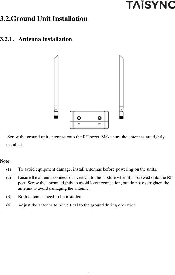
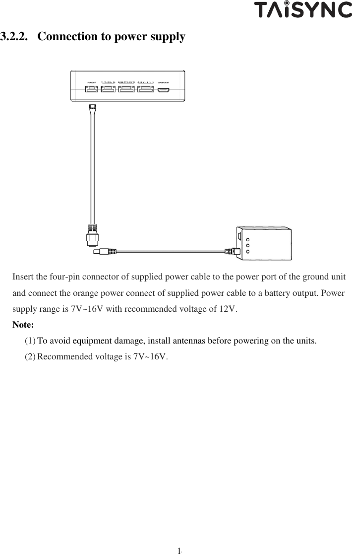
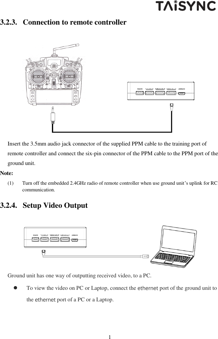
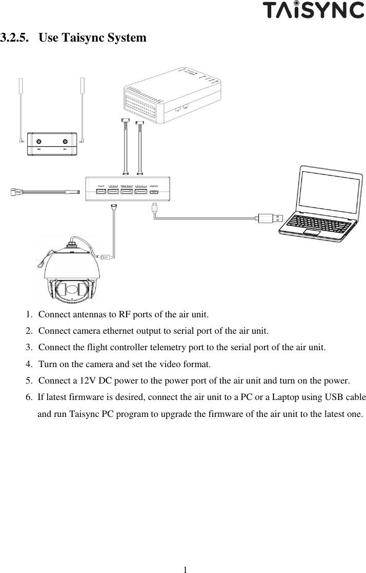
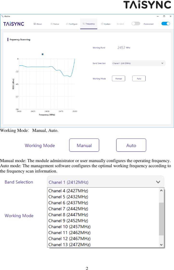
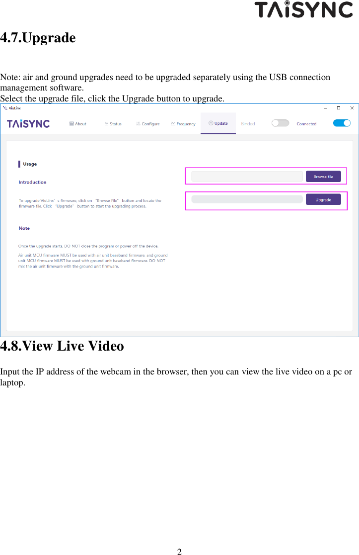
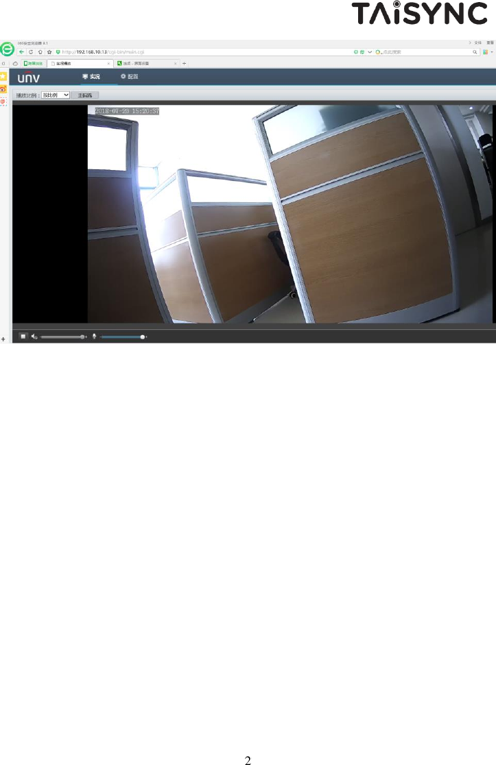
User Manual
Discussion / Help
Navigation