Taisync Technology T18V12110 2.4GHz HD Wireless Link User Manual
Taisync Technology LLC 2.4GHz HD Wireless Link Users Manual
Users Manual
1
Taisync
User Manual
www.taisync.com

2
Contents
1. Package Contents ............................................................................. 3
2. Product Description ......................................................................... 5
2.1. Air Unit Interfaces ................................................................. 5
2.2. Ground Unit Interfaces .......................................................... 6
3. Installation........................................................................................ 9
3.1. Air Unit Installation ............................................................... 9
3.1.1. Antenna installation .................................................... 9
3.1.2. Connection to power supply ..................................... 10
3.1.3. Connection to camera ............................................... 11
3.1.4. Connection to flight controller .................................. 12
3.2. Ground Unit Installation ...................................................... 13
3.2.1. Antenna installation .................................................. 13
3.2.2. Connection to power supply ..................................... 14
3.2.3. Connection to remote controller ............................... 15
3.2.4. Setup Video Output................................................... 15
3.2.5. Use Taisync System .................................................. 16
4. Software ......................................................................................... 17
4.1. Installation ........................................................................... 17
4.2. Language Selection ............................................................. 20
4.3. Device Info. ......................................................................... 21
4.4. Status ................................................................................... 22
4.5. Configuration ....................................................................... 22
4.6. Frequency Scan ................................................................... 24
4.7. Upgrade ............................................................................... 26
4.8. View Live Video ................................................................. 26
3
1. Package Contents
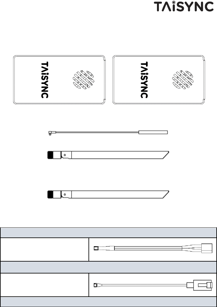
Air Unit & Ground Unit
Air Antenna × 2
(2dbi)
(5dbi)
Note:Air unit can choose 2dbi or 5dbi antenna.
Ground Antenna × 2
(5dbi)
Note:Ground unit use 5dbi antenna.
Air Unit Cables
Power cable x1
This is used to connect the output
of a battery to the power input of
the air unit.
ETH cable x1
This is used to connect the ethernet
output of camera to the Serial input
of the air unit.
Serial cable x1
4
This is used to connect the
telemetry port of flight controller to
the serial port of the air unit.
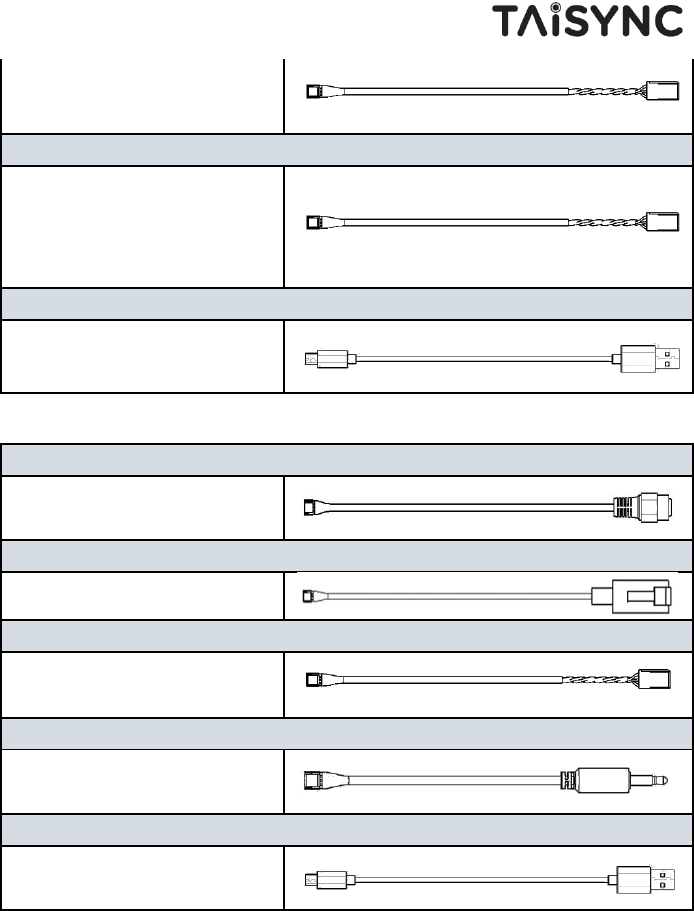
PPM cable x1
This is used to connect the PPM
training port of a remote controller
to the serial port of the air unit.
USB cable (Micro to Type-A)×1
This is used to connect the USB
port of a PC or a cell phone, to the
Micro USB port of the ground unit.
Ground Unit Cables
Power cable x1
This is used to connect the output
of a battery to the power input of
the ground unit.
ETH cable x1
This is used to connect the video
output of the ground unit.
Serial cable x1
This is used to connect the
telemetry port of flight controller to
the serial port of the ground unit.
PPM cable x1
This is used to connect the PPM
training port of a remote controller
to the serial port of the ground unit.
USB cable (Micro to Type-A)×1
This is used to connect the USB
port of a PC or a cell phone, to the
Micro USB port of the ground unit.
5
2. Product Description
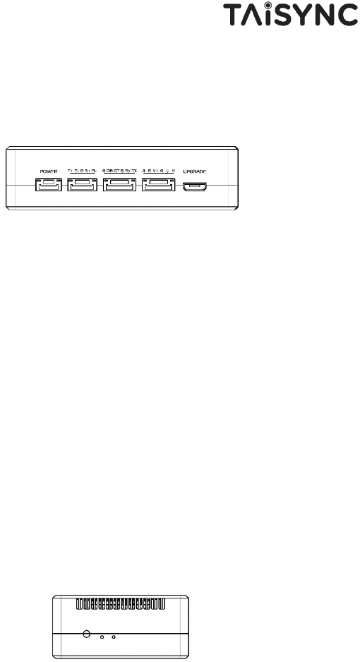
2.1.Air Unit Interfaces
① Power Input Port
Connect a 7V ~ 16V power source to this port. The power supply recommended 2s-3s
battery.
② Serial port
Connect the ethernet output of camera to the Serial input of the air unit.
③ Serial port
Connect this port to the telemetry port of a flight controller for data communication with
the air unit, can also be used to adjust the parameters.
④ Serial port
Connect this port to the telemetry port of a flight controller for telemetry communication
with the air unit.
⑤ Micro USB Port
Connect this port to the USB port of a PC or Laptop, and use the Taisync PC program to
upgrade firmware and set parameters on the air unit.
① BIND Button
Press this button to perform the binding operation.
② LED 1
③
②
①
①
④
⑤
③
②
6
When this LED is on, it means the air-to-ground link is connected; when this LED is off, it
means the air-to-ground link is disconnected.
③ LED 2
When this LED is on, it means the ground -to-air link is connected; when this LED is off,
it means the ground -to-air link is disconnected.
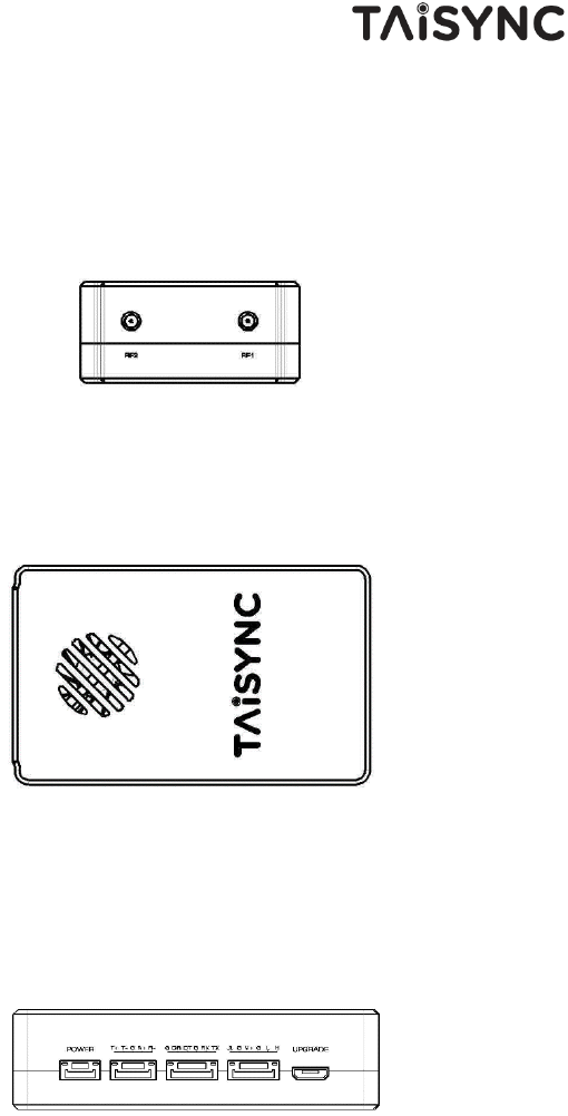
① RF2 port
Connect the 2nd air unit antenna to this port.
② RF1 port
Connect the air unit antenna to this port.
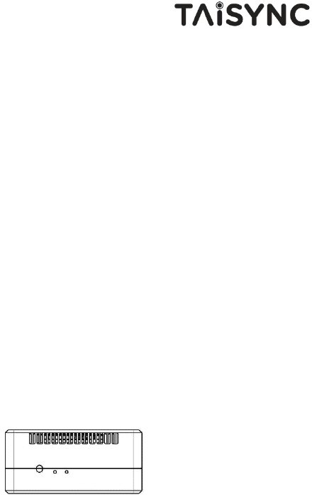
① Fan Ventilation Outlet
Don’t block this fan ventilation outlet to ensure effective cooling.
2.2.Ground Unit Interfaces
① Power Input Port
②
①
①
①
②
③
④
⑤
7
Connect a 7V ~ 16V power source to this port. The power supply recommended 2s-3s
battery.
② Serial port
Connect this serial output port to the ethernet input port of a display device using the
supplied serial-eth cable.
③ Serial port
Connect this port to the telemetry port of a flight controller for data communication with
the ground unit, can also be used to adjust the parameters.
④ Serial port
Connect this port to the telemetry port of a flight controller for telemetry communication
with the ground unit.
⑤ Micro USB Port
Connect this port to the USB port of a PC or Laptop, and use the Taisync PC program to
upgrade firmware and set parameters on the ground unit.
① BIND Button
Press this button to perform the binding operation.
② LED 1
When this LED is on, it means the air-to-ground link is connected; when this LED is off,
it means the air-to-ground link is disconnected.
③ LED 2
When this LED is on, it means the ground -to-air link is connected; when this LED is off,
it means the ground -to-air link is disconnected.
①
②
③
8
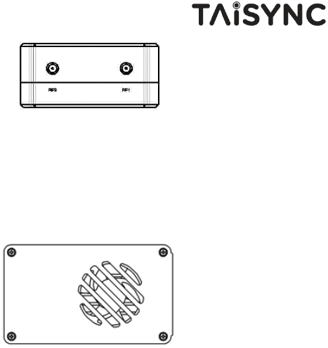
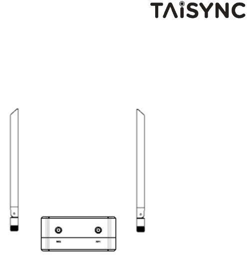
① RF2 port
Connect the 2nd air unit antenna to this port.
② RF1 port
Connect the air unit antenna to this port.
① Fan Ventilation Outlet
Don’t block this fan ventilation outlet to ensure effective cooling.
①
①
②
9
3. Installation
3.1.Air Unit Installation
3.1.1. Antenna installation
Insert the air unit antennas into the RF ports. Antenna clicks in when properly installed.
Note:
(1) To avoid equipment damage, install antennas before powering on the units.
(2) When install air unit to drone, avoid the antennas being blocked by parts of the drone.
(3) Both antennas need to be installed.
(4) Ensure the antenna connector is vertical to the module when it is pushed into the RF
port.
(5) When uninstall the antenna, hold the connector and pull it out of the RF port. Do not
pull the cable.
10
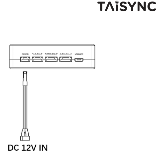
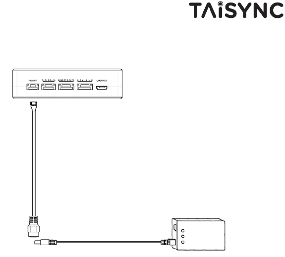
3.1.2. Connection to power supply
Insert the four-pin connector of supplied power cable to the power port of the air unit and
connect the orange power connect of supplied power cable to a battery output, or the
power supply port of a drone. Power supply range is 7V~16V with recommended voltage
of 12V.
Note:
(1) To avoid equipment damage, install antennas before powering on the units.
(2) Recommended voltage is 7V~16V.
11
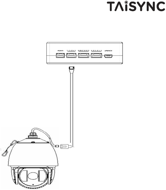
3.1.3. Connection to camera
Connect the ethernet video output port to the serial video input port of the air unit.
12
3.1.4. Connection to flight controller
Insert the six-pin connector of supplied serial cable to the serial port of the air unit and
connect the other end of the serial cable to the telemetry port of a flight controller.
13
3.2.Ground Unit Installation
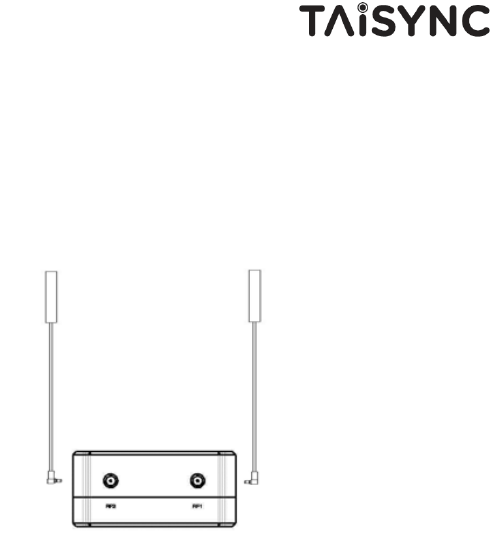
3.2.1. Antenna installation
Screw the ground unit antennas onto the RF ports. Make sure the antennas are tightly
installed.
Note:
(1) To avoid equipment damage, install antennas before powering on the units.
(2) Ensure the antenna connector is vertical to the module when it is screwed onto the RF
port. Screw the antenna tightly to avoid loose connection, but do not overtighten the
antenna to avoid damaging the antenna.
(3) Both antennas need to be installed.
(4) Adjust the antenna to be vertical to the ground during operation.
14
3.2.2. Connection to power supply
Insert the four-pin connector of supplied power cable to the power port of the ground unit
and connect the orange power connect of supplied power cable to a battery output. Power
supply range is 7V~16V with recommended voltage of 12V.
Note:
(1) To avoid equipment damage, install antennas before powering on the units.
(2) Recommended voltage is 7V~16V.
15
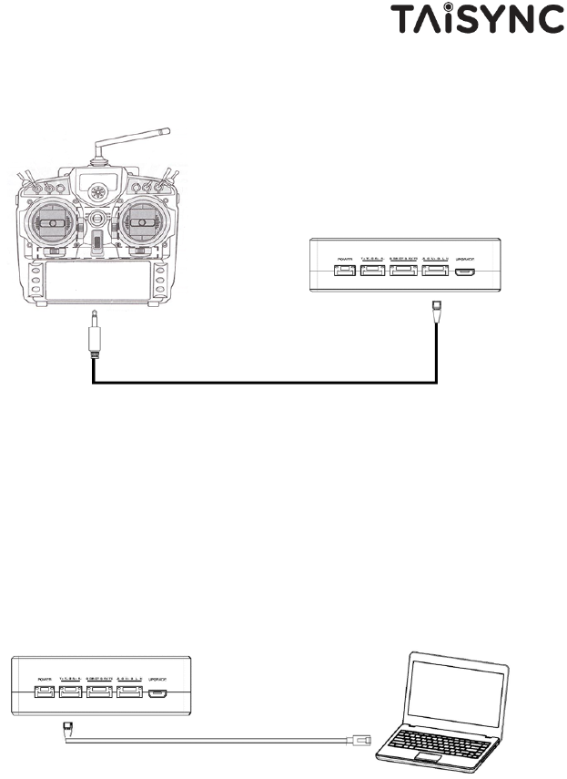
3.2.3. Connection to remote controller
Insert the 3.5mm audio jack connector of the supplied PPM cable to the training port of
remote controller and connect the six-pin connector of the PPM cable to the PPM port of the
ground unit.
Note:
(1) Turn off the embedded 2.4GHz radio of remote controller when use ground unit’s uplink for RC
communication.
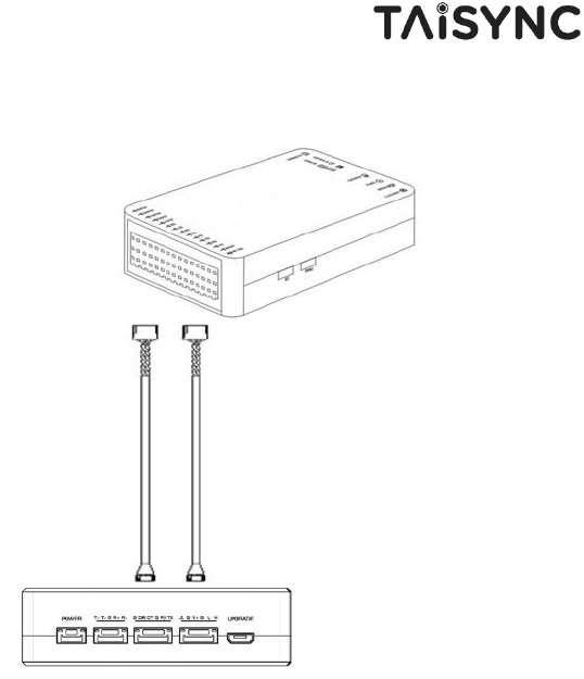
3.2.4. Setup Video Output
Ground unit has one way of outputting received video, to a PC.
⚫ To view the video on PC or Laptop, connect the ethernet port of the ground unit to
the ethernet port of a PC or a Laptop.
16
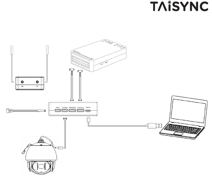
3.2.5. Use Taisync System
1. Connect antennas to RF ports of the air unit.
2. Connect camera ethernet output to serial port of the air unit.
3. Connect the flight controller telemetry port to the serial port of the air unit.
4. Turn on the camera and set the video format.
5. Connect a 12V DC power to the power port of the air unit and turn on the power.
6. If latest firmware is desired, connect the air unit to a PC or a Laptop using USB cable
and run Taisync PC program to upgrade the firmware of the air unit to the latest one.
17
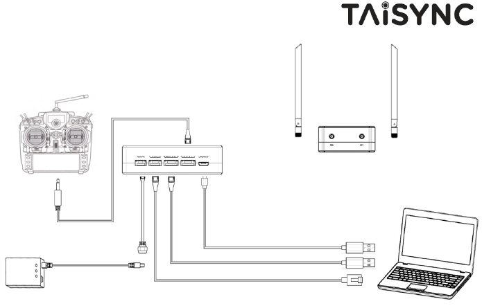
1. Connect antennas to RF ports of the ground unit.
2. Connect the remote controller’s PPM output to the serial port of the ground unit if
you want to use Taisync’s command uplink.
3. If video view on a PC or a Laptop is desired, connect a PC or a Laptop to the seriald
port of the ground unit.
4. Connect a 12V DC power to the power port of the ground unit and turn on the
power.
5. If latest firmware is desired, connect the ground unit to a PC or a Laptop using USB
cable and run Taisync PC program to upgrade the firmware of the ground unit to
the latest one.
4. Software
4.1.Installation
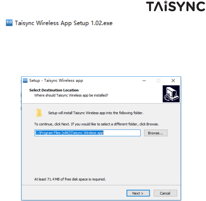
We provide program installation files, program file name: Taisync Wireless App Setup.exe.
The installer icon is as follows:
18
Double-click the installer to install and customize the program installation directory. After
configuration, click the “Next” button to jump to the next step. To cancel the installation,
click the “Cancel” button.
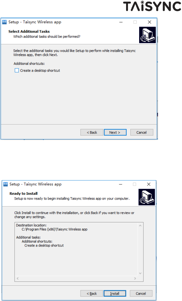
Check the Generate desktop shortcut. If it is not checked, the desktop shortcut will not be
generated. After configuration, click the “Next” button to jump to the next step. To rewind
the previous step, click the “Back” button. To cancel the installation, click the Cancel
button.
19
Click “Install” to proceed with the installation. To rewind the previous step, click the “Back”
button. To cancel the installation, click the “Cancel” button.
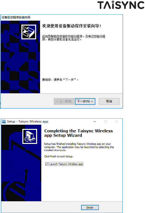
Note: Please turn off the firewall software, otherwise the firewall may prevent the
driver from being installed when the driver is installed.
20
At this point, the software installation is successful and the driver installation is complete.
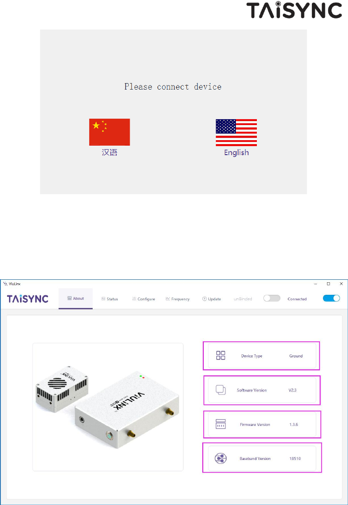
4.2.Language Selection
Software supports Chinese and English display.
21
4.3.Device Info.
Readable device status information: device type, software version, firmware version, and
baseband version.
22
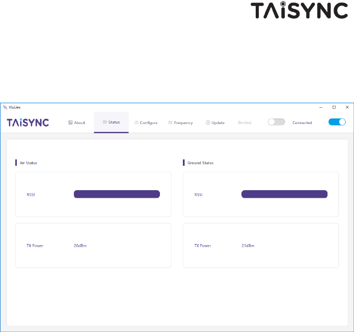
4.4.Status
Read the air and ground status information, can read double-ended information: RSSI
(received signal strength indication), Tx_Power.
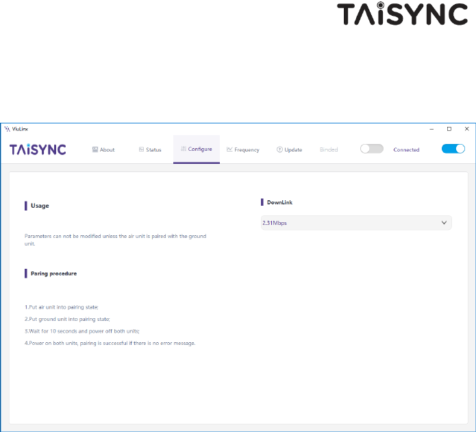
4.5.Configuration
For parameter configuration, device bind is required.
“Bind” is used to pair an air unit with ground unit.
To pair an air unit and an ground unit,
1. Connect the air and ground devices.
2. Press the bind button of the air device.
3. Press the bind button of the ground device.
4. Power off both units for at least 10 seconds.
23
5. Power on both units. If the two units are not binded, “unbind” is shown under
“BIND” status in Ground Status section. If the two units are binded, “binded” is shown
under “BIND” status in Ground Status section.
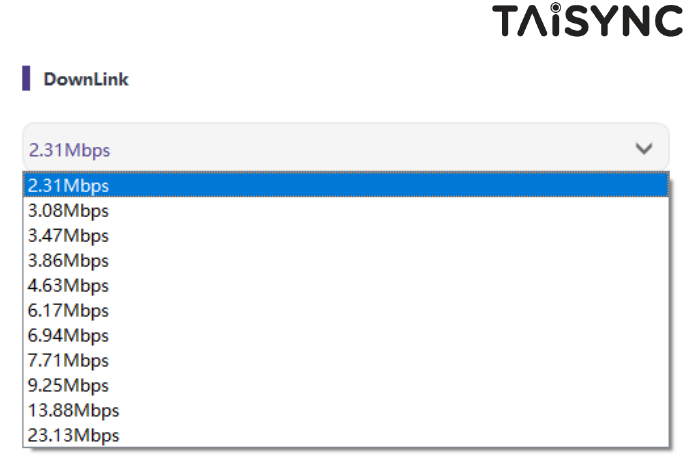
The downlink mode adjustment interface is as follows:
24
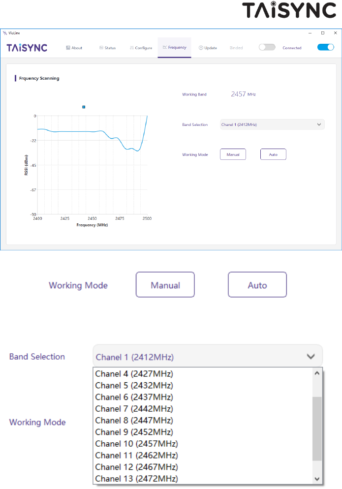
4.6.Frequency Scan
Provides signal strength scan information for the 2.4G band.
25
Working Mode:Manual, Auto.
Manual mode: The module administrator or user manually configures the operating frequency.
Auto mode: The management software configures the optimal working frequency according to
the frequency scan information.
26
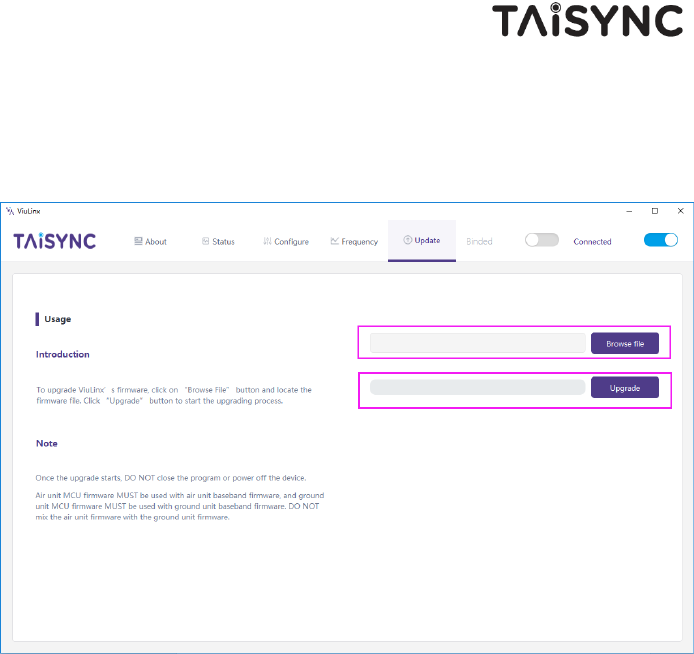
4.7.Upgrade
Note: air and ground upgrades need to be upgraded separately using the USB connection
management software.
Select the upgrade file, click the Upgrade button to upgrade.
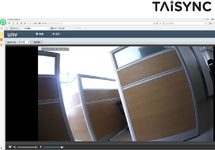
4.8.View Live Video
Input the IP address of the webcam in the browser, then you can view the live video on a pc or
laptop.
27
Federal Communications Commission (FCC) Interference Statement
This equipment has been tested and found to comply with the limits for a Class B digital device, pursuant to Part
15 of the FCC Rules.
These limits are designed to provide reasonable protection against harmful interference in a residential
installation. This equipment generate, uses and can radiate radio frequency energy and, if not installed and used
in accordance with the instructions, may cause harmful interference to radio communications.
However, there is no guarantee that interference will not occur in a particular installation. If this equipment does
cause harmful interference to radio or television reception, which can be determined by turning the equipment
off and on, the user is encouraged to try to correct the interference by one of the following measures:
Reorient or relocate the receiving antenna.
Increase the separation between the equipment and receiver.
Connect the equipment into an outlet on a circuit different from that to which the receiver is
connected.
Consult the dealer or an experienced radio/TV technician for help.
This device complies with Part 15 of the FCC Rules. Operation is subject to the following two conditions:
(1) This device may not cause harmful interference, and (2) this device must accept any interference received,
including interference that may cause undesired operation.
FCC Caution: Any changes or modifications not expressly approved by the party responsible for compliance could
void the user’s authority to operate this equipment.
RF exposure warning
This equipment complies with FCC radiation exposure limits set forth for an uncontrolled environment.
This equipment must be installed and operated in accordance with provided instructions and the antenna(s) used
for this transmitter must be installed to provide a separation distance of at least 20 cm from all persons and must
not be collocated or operating in conjunction with any other antenna or transmitter.