Tait TBAB1A Base Station Tranceiver User Manual Exhibit D Users Manual per 2 1033 c3
Tait Limited Base Station Tranceiver Exhibit D Users Manual per 2 1033 c3
Tait >
Exhibit D Users Manual per 2 1033 c3
TB8100 Installation and Operation Manual Appendix 1: 12V PA i
© Tait Electronics Limited December 2004
Appendix 1: 12V PA
Boost Regulator Circuit Description
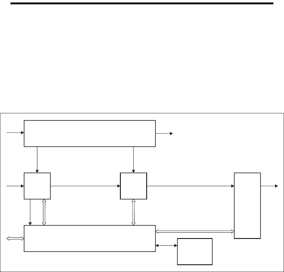
This section provides a brief description of the circuitry on the boost
regulator board. Figure 1.1 below shows the configuration for a 5W or
50W PA, along with the main inputs and outputs for power, RF and control
signals. Note that the 60W board is only fitted to the 50W PA. The circuit
description for the rest of the PA is provided in the “Circuit Description”
chapter.
The boost regulator board accepts an input of 12VDC nominal. The input
is firstly fed through the DC input filter, and is then fed through an output
filter to provide the 12VDC (nominal) output for the reciter. The output
from the DC input filter is also fed to the power stage where the voltage is
boosted to 28VDC, and is then fed through an output filter to provide the
28VDC output for the PA circuit boards.
The battery control circuitry monitors the DC input voltage from the
battery. Protection is provided against the wrong input voltage being
supplied. The battery control circuitry also prevents deep discharge of the
battery.
Figure 1.1 5W or 50W PA high level block diagram
6W
Board
Control Board
Boost Regulator
60W
Board
Ambient Air
Temperature
Sensor
Board
Low-Pass
Filter
&
Directional
Coupler
Board
RF I/P +
PA Key RF O/P
12VDC
I/P
12VDC O/P
(Reciter)
DC
28VDC28VDC
RF RF
Control &
Monitor
Control &
Monitor
Control &
Monitor
System
Control
Bus
ii Appendix 1: 12V PA TB8100 Installation and Operation Manual
© Tait Electronics Limited December 2004
Overview of Inputs and Outputs
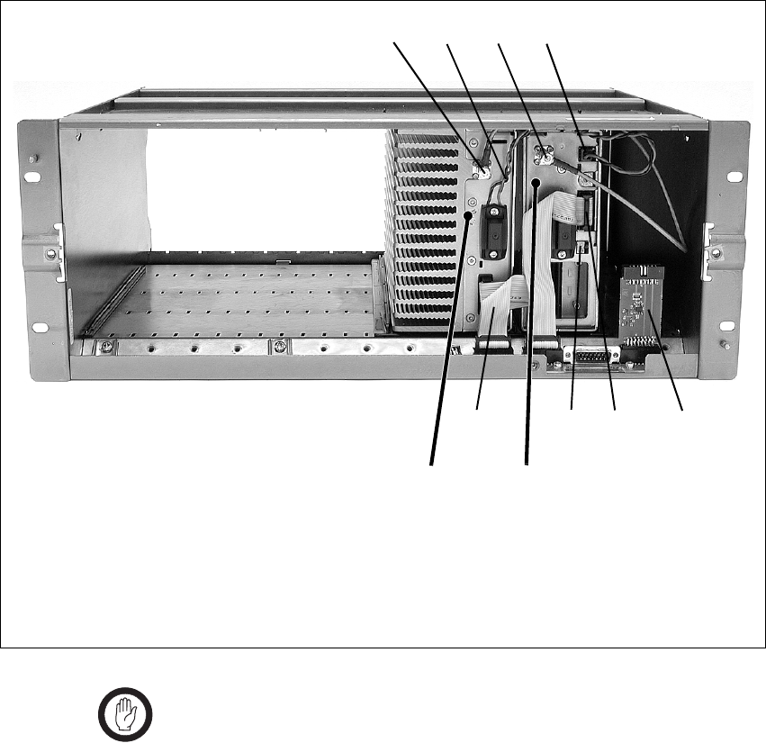
This section identifies the main input and output connections for the
TB8100 BSS with 12V PA. Figure 1.2 below identifies the connections at
the front of the base station, and Figure 1.3 on page iii identifies those at the
rear. Refer to the “Connection” chapter for more details.
Important The system control bus terminating circuitry board must be
connected to the system control bus at all times. If the
board is disconnected, the state of much of the bus will be
undefined. This may cause corrupted data to be present on
the bus when the reciter reads the states of the switches on
the control panel. This in turn may result in random actu-
ations of microphone PTT, carrier, or speaker key, causing
the BSS to transmit or the speaker to be actuated incor-
rectly.
Figure 1.2 5W or 50W base station inputs and outputs - front view
bRF input from reciter fterminating circuitry for system control bus
c12VDC low current output for reciter gsystem control bus
dRF output to PA hDC output (for optional reciter fan only)
e12VDC low current input from PA
bdec
gfgh
PA reciter
TB8100 Installation and Operation Manual Appendix 1: 12V PA iii
© Tait Electronics Limited December 2004
DC Power
The TB8100 12V PA is designed to accept a nominal 12VDC input with
negative ground. There is a minimum DC start-up threshold to prevent
damaging a battery which has little capacity left.
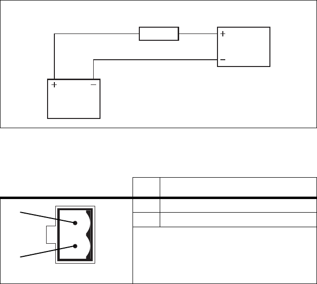
You must connect the DC supply from the battery to the PA via a fuse or
DC-rated circuit breaker with the appropriate rating, as shown in the table
below. The DC input leads should be of a suitable gauge to ensure less than
0.2V drop at maximum load over the required length of lead.
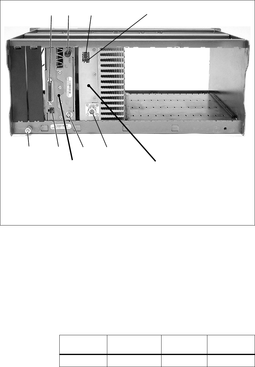
Figure 1.3 5W or 50W base station inputs and outputs - rear view
bsystem interface connector fRF output
cexternal reference frequency input gRF input
d12VDC input hauxiliary DC input for system interface
ePower Saving control input isubrack ground connector
cd e
fgh
PA
reciter
b
i
Nominal Supply
Voltage
Input Voltage
Range
Circuit Breaker/
Fuse Rating
Recommended
Wire Gaugea
a. For a length of 1.5m to 2m (5ft to 6.5ft) (typical).
12VDC 10.6VDC to 16.8VDC 20A 2AWG / 35mm2
iv Appendix 1: 12V PA TB8100 Installation and Operation Manual
© Tait Electronics Limited December 2004
The pin allocations for the 2-way DC input connector are shown below.
Figure 1.4 Recommended DC power connection
Pin Description
1 +V input
2ground
Battery
PMU
Circuit Breaker
or Fuse
2-way connector - external view
b
c