Tait TBCH1B Base Station Transceiver User Manual TB9400 Installation and Operation Manual
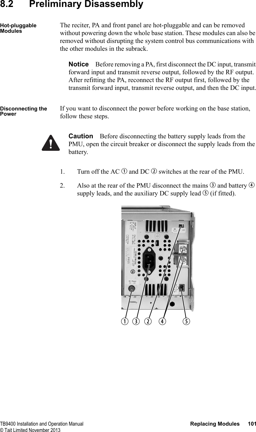
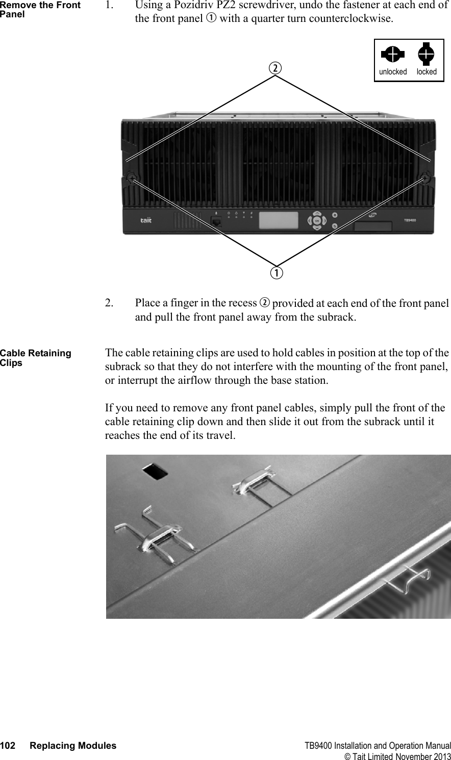
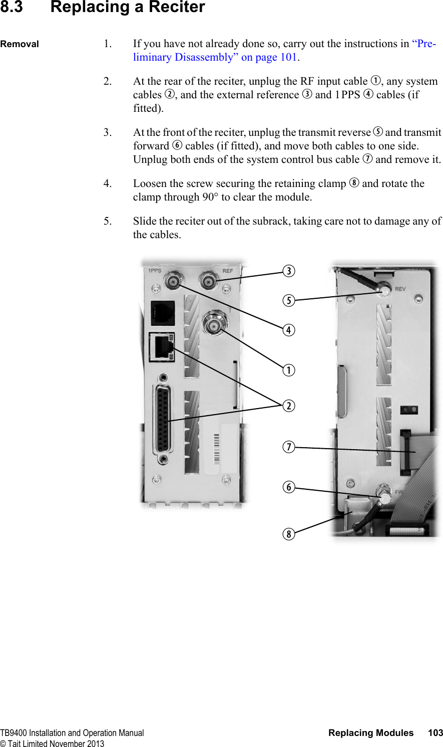
Tait Limited Base Station Transceiver TB9400 Installation and Operation Manual
UserManual.wiki
>
Tait
>
TBCH1B User Manual
Exhibit D Users Manual per 2 1033 c3
Navigation menu
Upload a User Manual
Namespaces
Wiki Guide
HTML
PDF
Info
Views
User Manual
Discussion / Help
Navigation
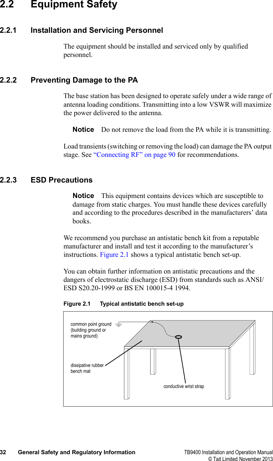
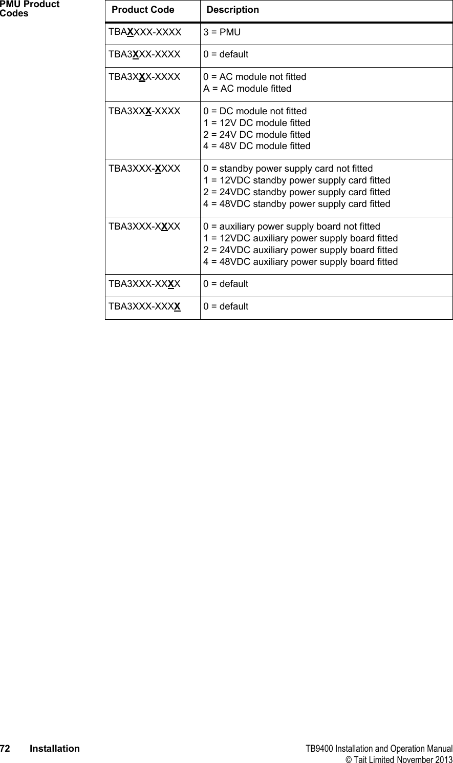
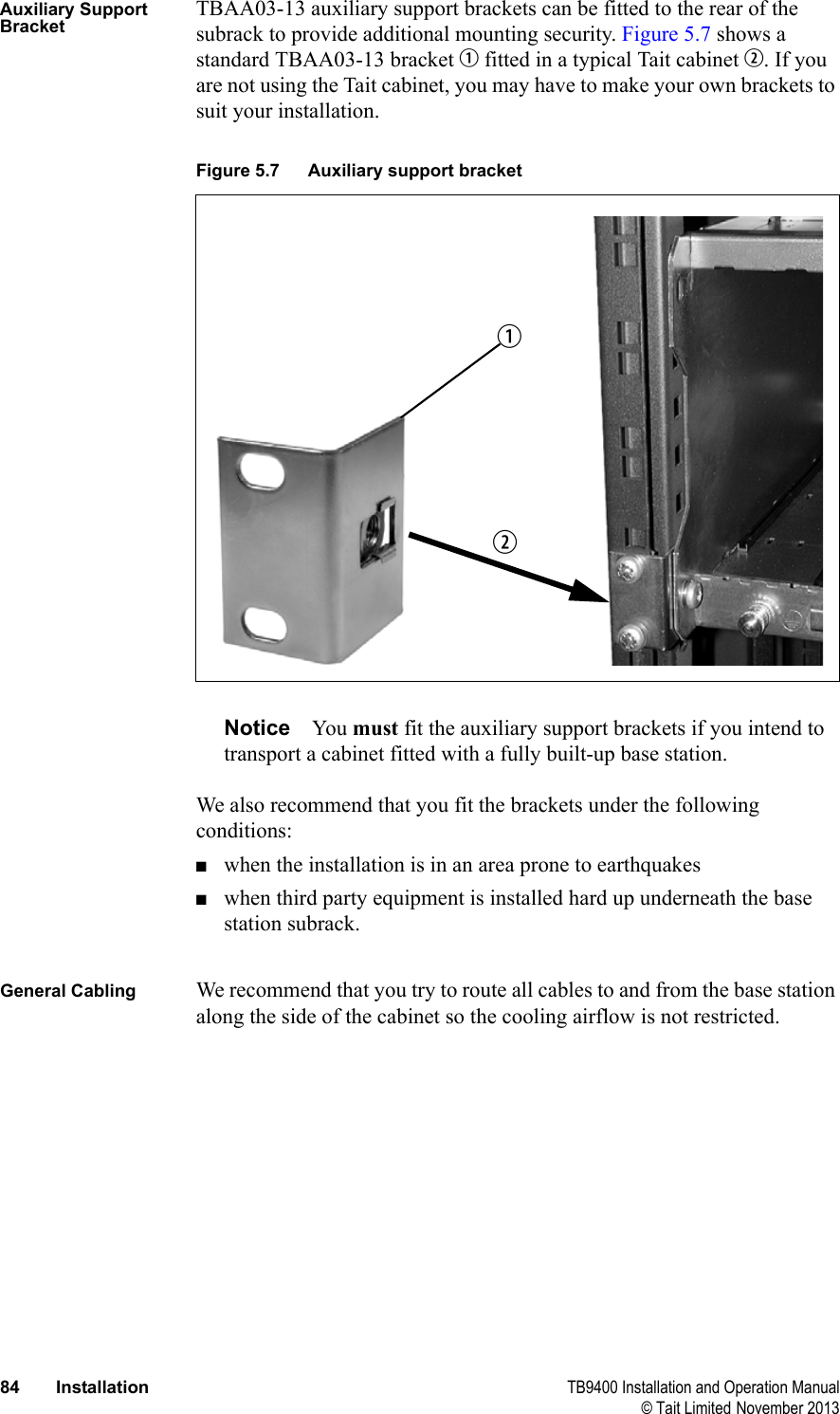
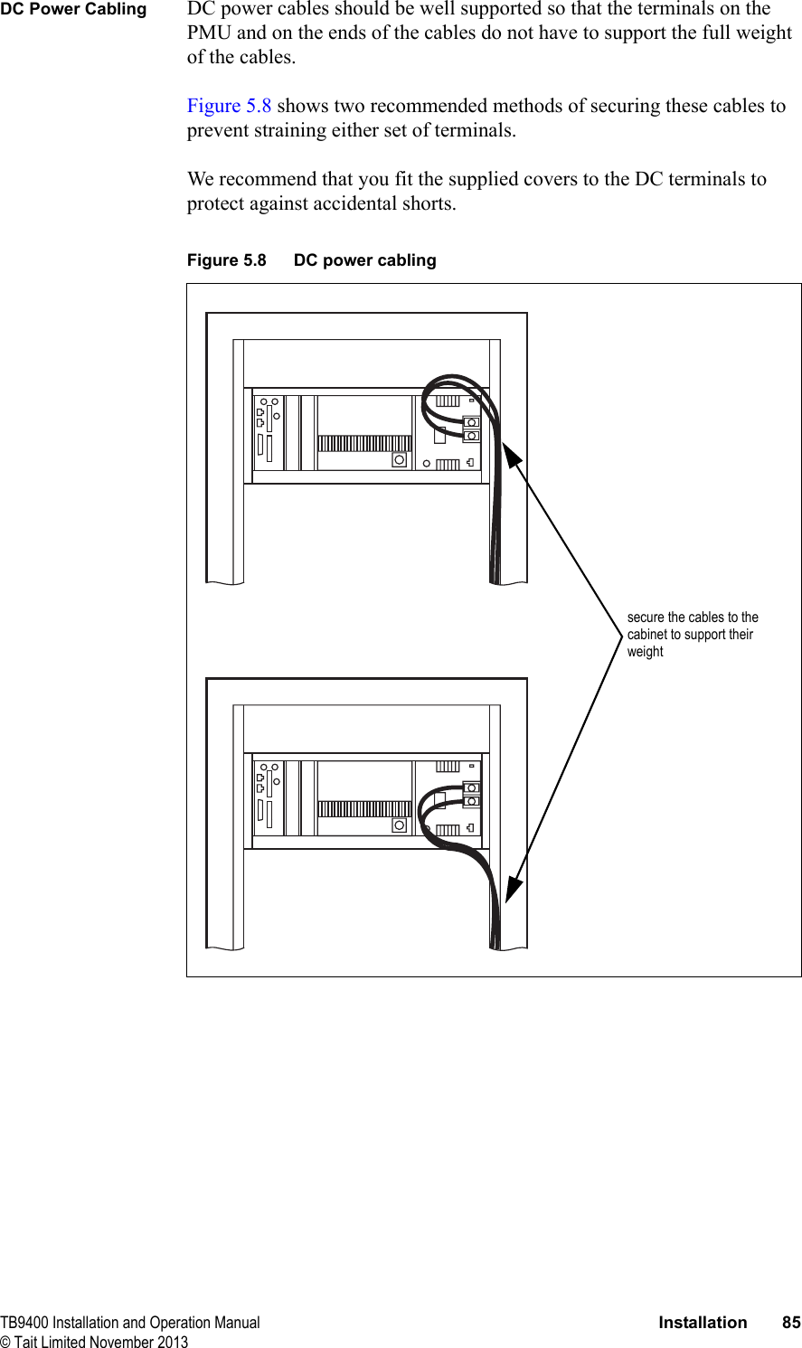
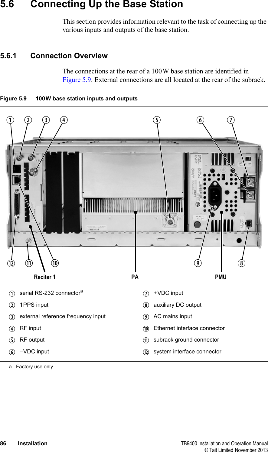
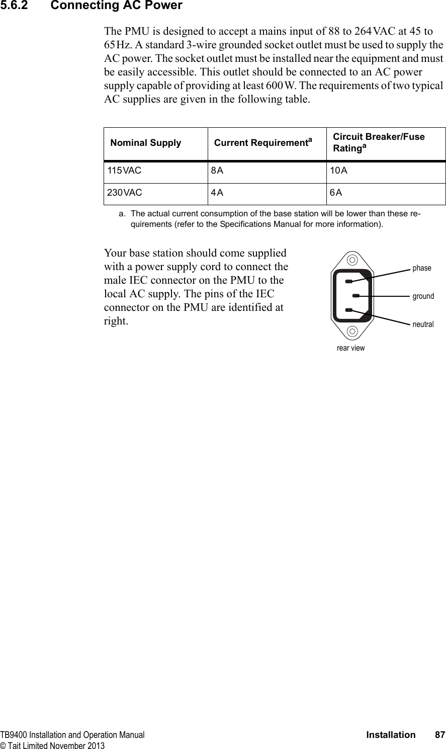
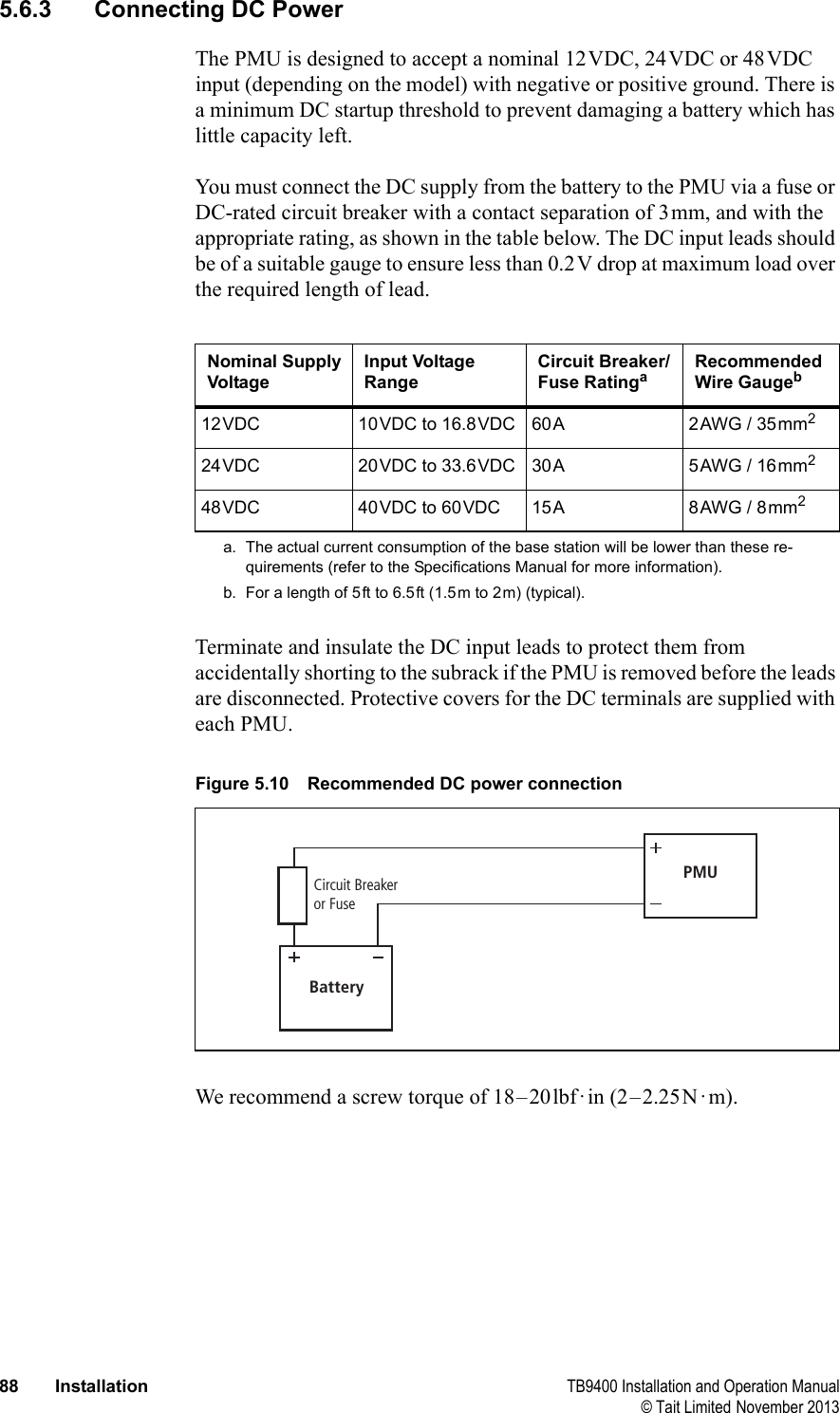
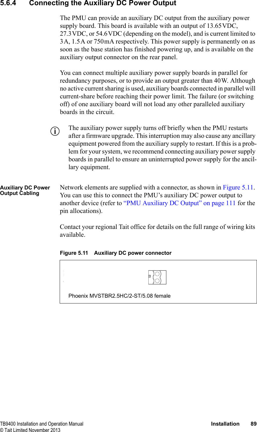
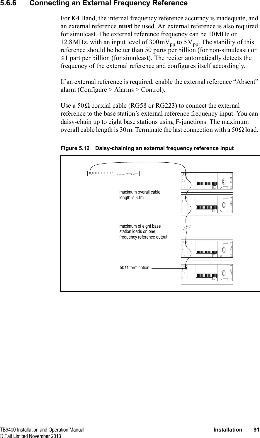
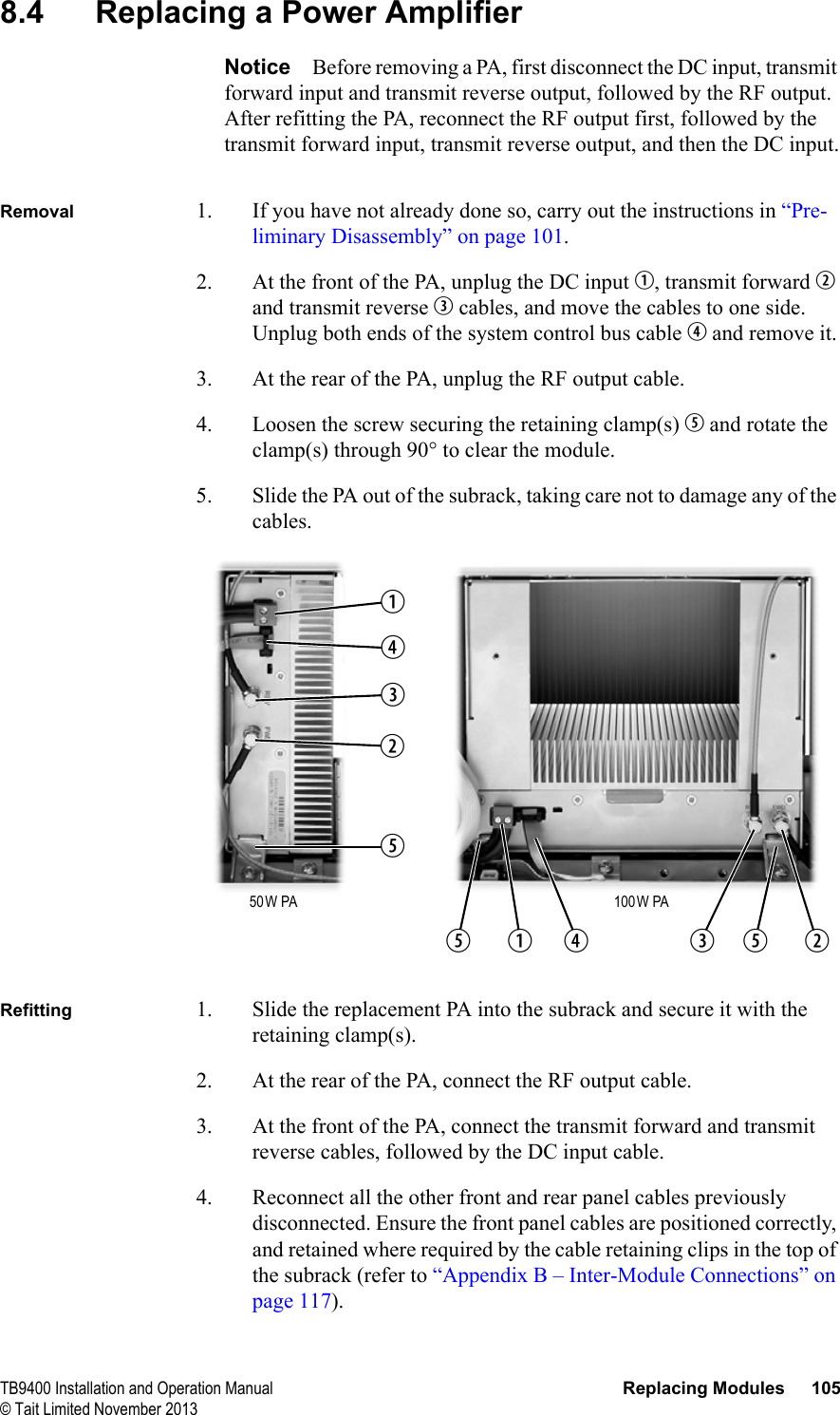
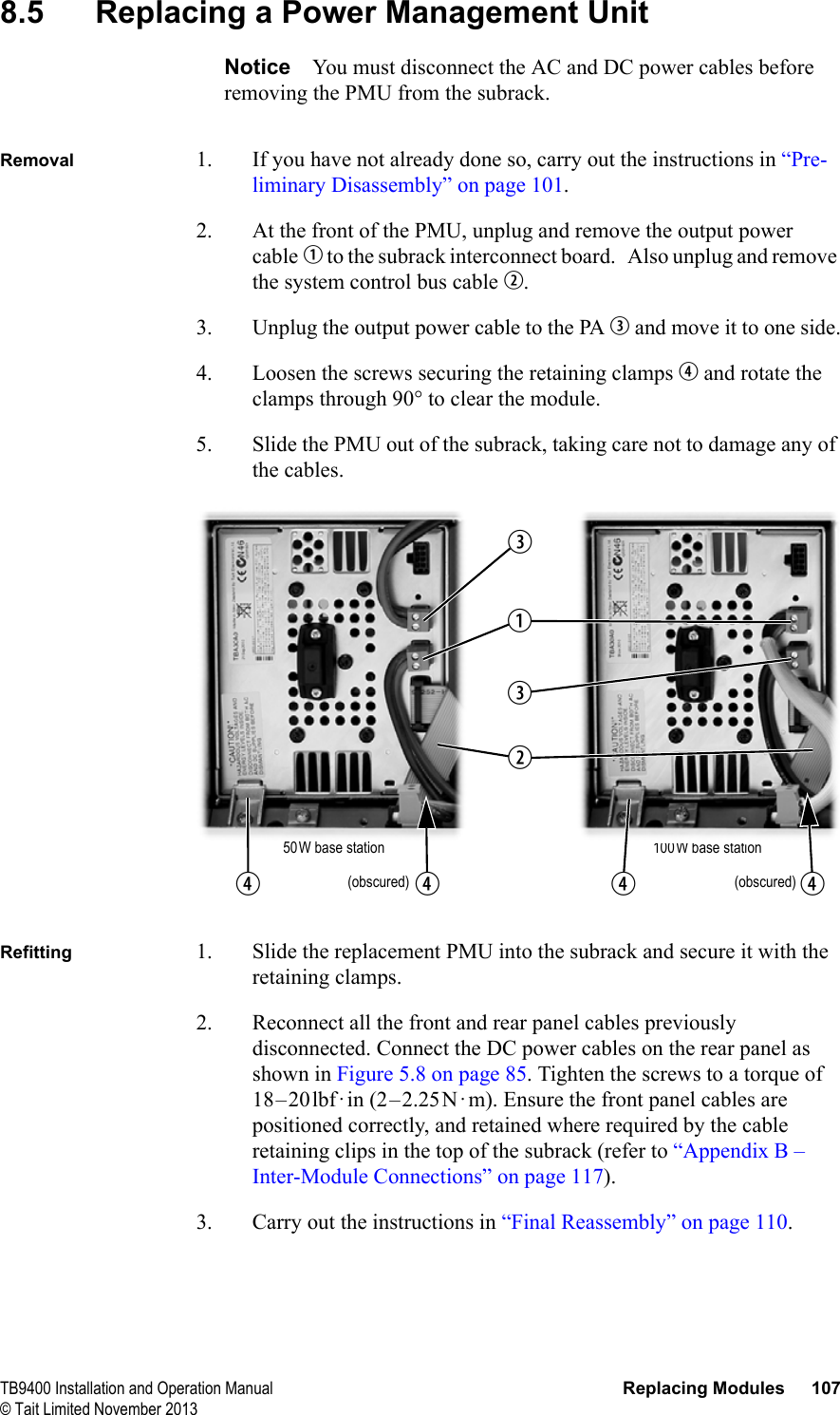
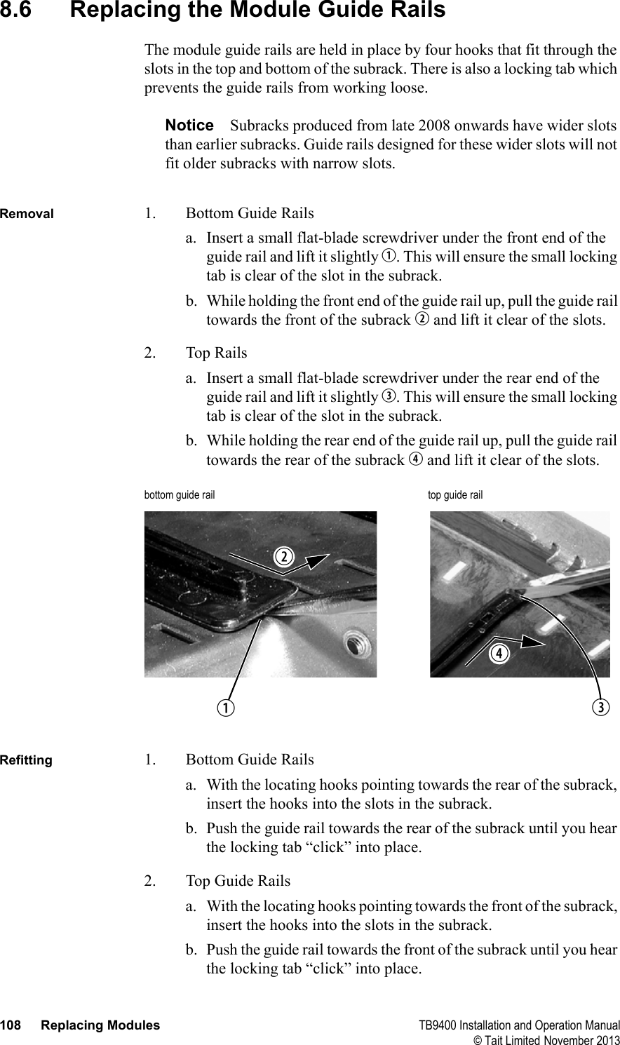
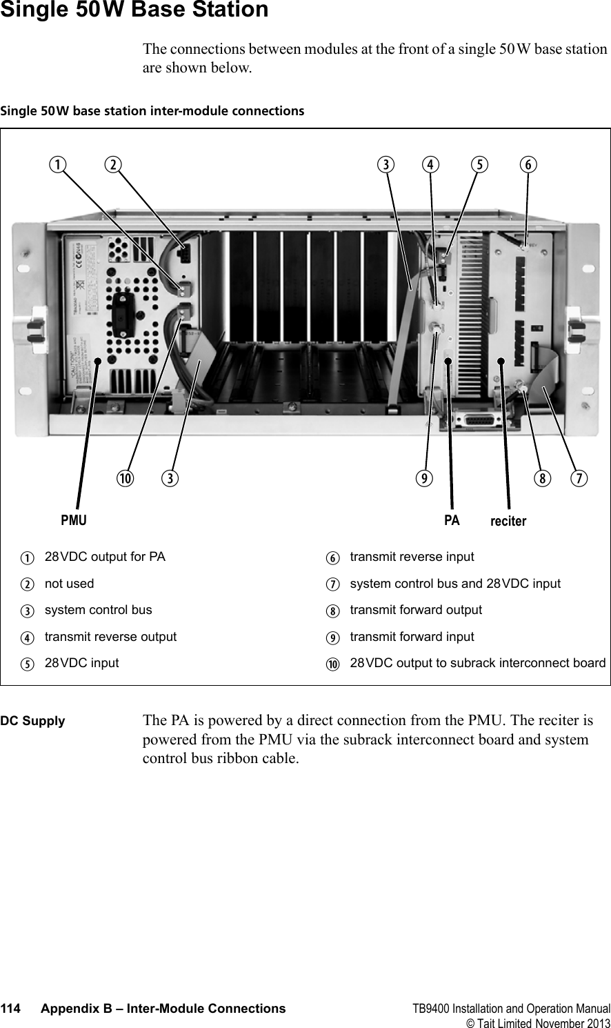
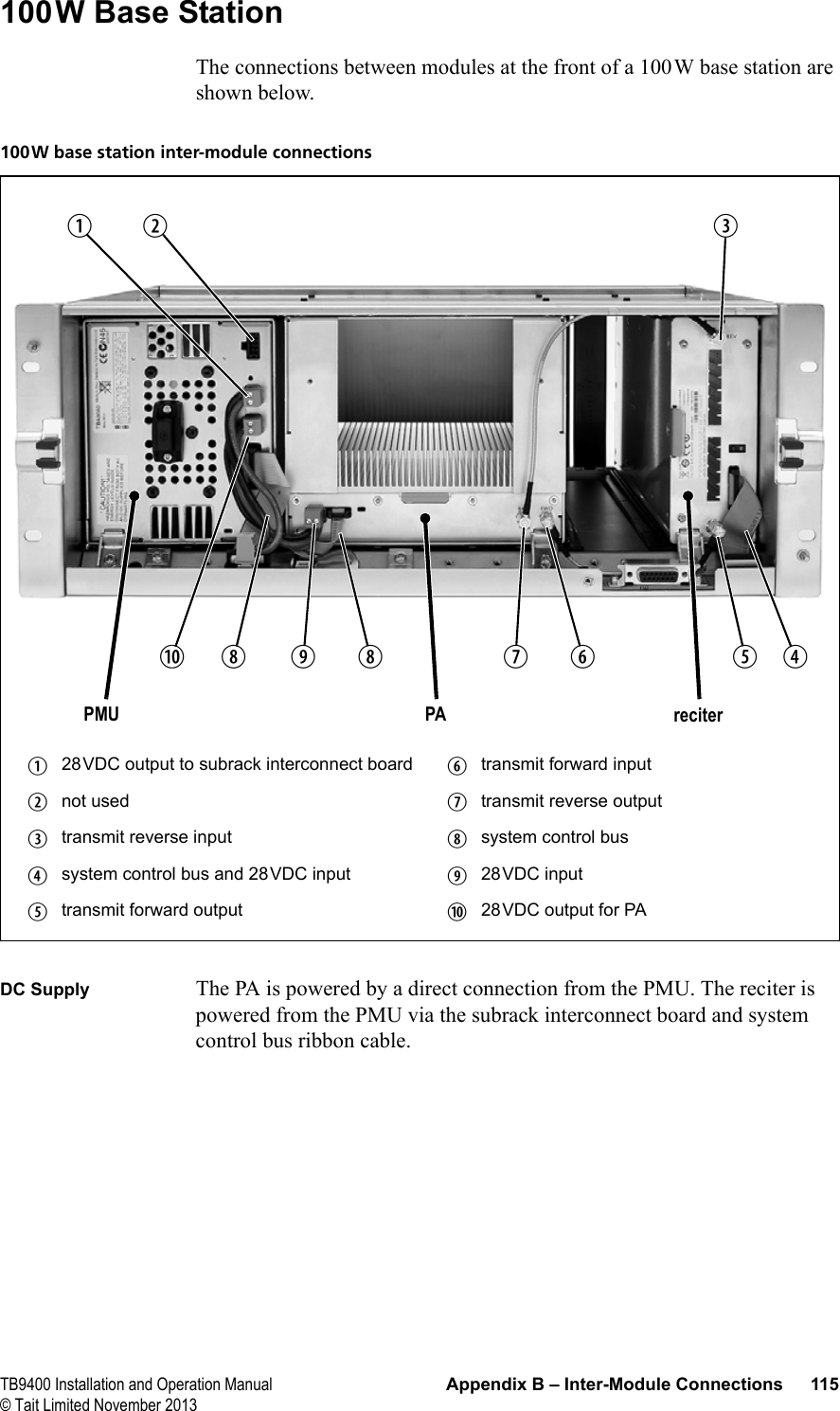
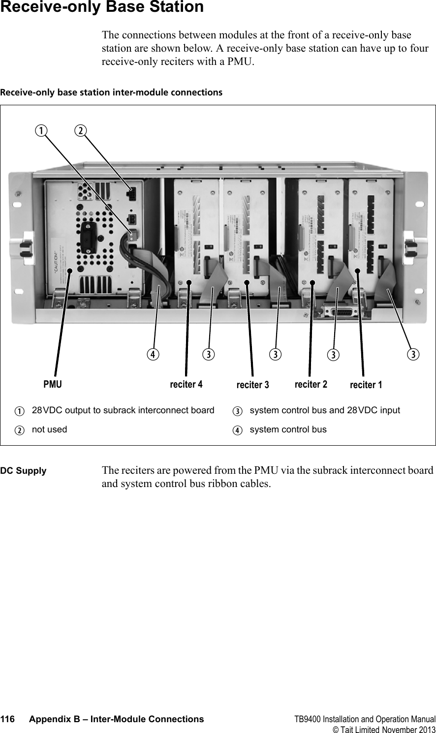
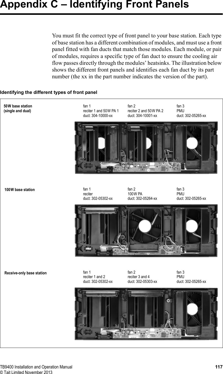
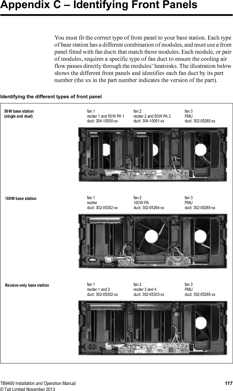
![TB9400 Installation and Operation Manual General Safety and Regulatory Information 31© Tait Limited November 20132.1.3 AC Power Connection2.1.4 Explosive EnvironmentsWarning Do not operate the equipment near electrical blasting caps or in an explosive atmosphere. Operating the equipment in these environments is a definite safety hazard.2.1.5 Proximity to RF TransmissionsDo not operate the transmitter when someone is standing within 3ft (90cm) of the antenna. Do not operate the transmitter unless you have checked that all RF connectors are secure.2.1.6 High TemperaturesTake care when handling a PMU or PA which has been operating recently. Under extreme operating conditions (+140°F [+60°C] ambient air temperature) or high duty cycles, the external surfaces of the PMU and PA can reach temperatures of up to +176°F (+80°C).2.1.7 LED Safety (EN60825-1)This equipment contains Class 1 LED Products.English (en) The PMU must be connected to a grounded mains socket-outlet.Norsk (no) Apparatet må tilkoples jordet stikkontakt.Suomi (fi) Laite on liitettävä suojamaadoitus-koskettimilla varustettuun pistorasiaan.Svenska (sv) Apparaten skall anslutas till jordat uttag.](https://usermanual.wiki/Tait/TBCH1B/User-Guide-2181470-Page-31.png)