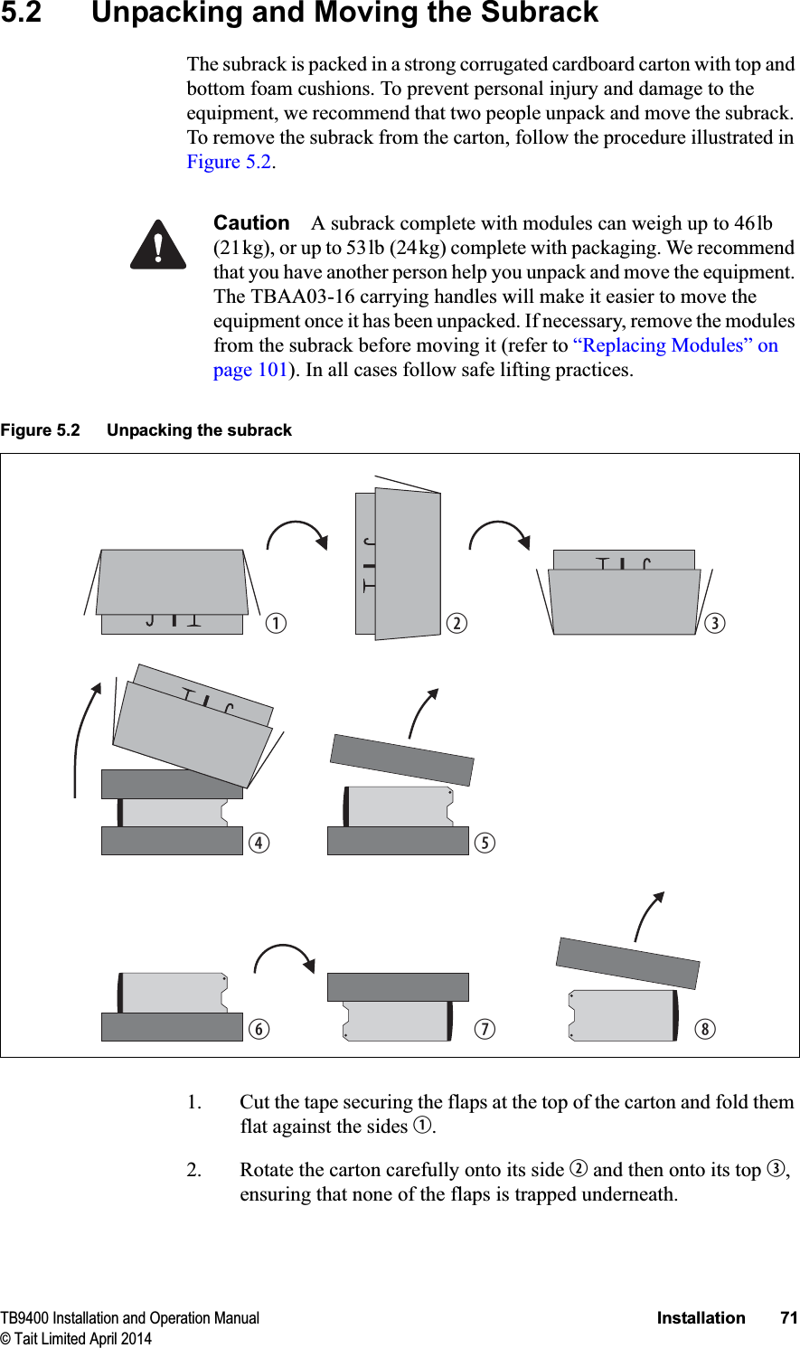
Tait TBCH2B Base Station Transceiver User Manual TB9400 Installation and Operation Manual

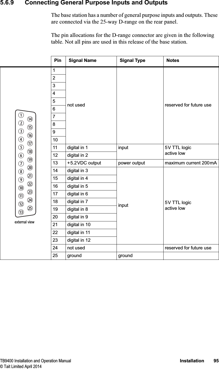
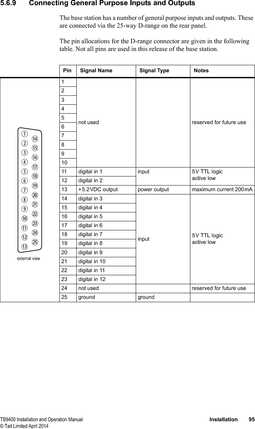
Tait Limited Base Station Transceiver TB9400 Installation and Operation Manual

Exhibit D Users Manual per 2 1033 c3

TB9400 Installation and Operation Manual Installation 67© Tait Limited April 20145InstallationThis chapter provides information on the site requirements for your TB9400 equipment and also describes how to install the base station in a standard 19 inch rack or cabinet.If this is your first time installing a TB9400 base station, we recommend that you read the entire chapter before beginning the actual installation.
68 Installation TB9400 Installation and Operation Manual© Tait Limited April 20145.1 Before You Begin5.1.1 Equipment SecurityThe security of your base station equipment is a high priority. If the site is not fully secure, the base station should at least be locked in a secure cabinet to prevent unauthorized access.5.1.2 Grounding and Lightning ProtectionElectrical Ground The base station modules are grounded by physical contact between the module case and the subrack. To ensure a good ground connection you must tighten each module retaining clamp securely (refer to “Final Reassembly” on page 112 for the correct torque).A threaded grounding connector is provided on the rear of the subrack for connection to the site ground point (refer to “Connecting Up the Base Station” on page 88 for more details).Lightning Ground It is extremely important for the security of the site and its equipment that you take adequate precautions against lightning strike. Because it is outside the scope of this manual to provide comprehensive information on this subject, we recommend that you conform to your country’s standards organization or regulatory body.5.1.3 Equipment VentilationAlways ensure there is adequate ventilation around the base station. Notice Do not operate it in a sealed cabinet. You must keep the ambient temperature within the specified range, and we strongly rec-ommended that you ensure that the cooling airflow is not restricted.Notice The cooling fans are mounted on the front panel and will only operate when the panel is fitted correctly to the front of the subrack. To ensure adequate airflow through the base station, do not operate it for more than a few minutes with the front panel removed (e.g. for servicing purposes).5.1.4 Ambient Temperature SensorThe ambient temperature reading for the base station is provided by the temperature sensor located on the front panel circuit board.
TB9400 Installation and Operation Manual Installation 69© Tait Limited April 20145.1.5 Cabinet and Rack VentilationThe cooling airflow for the base station enters through the front panel and exits at the rear of the subrack. For optimum thermal performance, the heated air that has passed through a base station must not be allowed to re-enter the air intakes on the front panel. Any space at the front of the cabinet not occupied by equipment should be covered by a blanking panel. Refer to Figure 5.1 on page 70.To allow enough cooling airflow through a cabinet-mounted base station, we recommend the following:■an area of at least 23in2(150cm2) of unrestricted ventilation slots or holes in front of the air intakes for the fans for each subrack; for example, thirty 0.25x3.3in (6x85mm) slots will allow the recommended airflow■a vent in the top of the cabinet with an area of approximately 23in2(150cm2) per subrack, or a similar area of ventilation per subrack at the rear of the cabinet behind each subrack■a 2U gap at the top of the cabinet.Notice The ventilation opening must be unrestricted. If the slots or holes are covered with a filter, mesh or grille, the open area must be increased to allow the same airflow as an unrestricted opening.The maximum ambient temperature entering the cabinet must not exceed +140°F (+60°C).If you are installing multiple subracks in a cabinet, ensure that there will be enough cooling airflow through the cabinet after the equipment has been installed. For example, the recommended maximum number of subracks in a 38U cabinet is five, as shown in Figure 5.1 on page 70.If the base station is installed in a rack or cabinet with other equipment with different ventilation requirements, we recommend that the base station be positioned below this equipment. Auxiliary Extractor FansThe base station does not require auxiliary extractor fans mounted in the top of the cabinet. If your cabinet is already fitted with fans, the following procedures apply:■if there are six or more 4.75in (12cm) fans, each capable of extracting 94.2 ft3 per minute (160m3 per hour), they must run continuously■if there are fewer than six fans, you must remove them and ensure the vent in the top of the cabinet has an area of approximately 23in2(150cm2) per subrack.If you have any other configuration, the performance of your system will depend on how closely you comply with the base station airflow requirements described above.
70 Installation TB9400 Installation and Operation Manual© Tait Limited April 2014Figure 5.1 Typical cabinet ventilation requirementsbventilation slots dairflow entrycblanking panels eairflow exit path8in(20cm)2U≥7in(≥17.5cm)side view front viewtop viewccdeb
TB9400 Installation and Operation Manual Installation 71© Tait Limited April 20145.2 Unpacking and Moving the SubrackThe subrack is packed in a strong corrugated cardboard carton with top and bottom foam cushions. To prevent personal injury and damage to the equipment, we recommend that two people unpack and move the subrack. To remove the subrack from the carton, follow the procedure illustrated in Figure 5.2.Caution A subrack complete with modules can weigh up to 46lb (21kg), or up to 53lb (24kg) complete with packaging. We recommend that you have another person help you unpack and move the equipment. The TBAA03-16 carrying handles will make it easier to move the equipment once it has been unpacked. If necessary, remove the modules from the subrack before moving it (refer to “Replacing Modules” on page 101). In all cases follow safe lifting practices.1. Cut the tape securing the flaps at the top of the carton and fold them flat against the sides b.2. Rotate the carton carefully onto its side c and then onto its top d,ensuring that none of the flaps is trapped underneath.Figure 5.2 Unpacking the subrackbegfhicd
72 Installation TB9400 Installation and Operation Manual© Tait Limited April 20143. Slide the carton upwards over the foam cushions and lift it away e.Remove the cushion from the bottom of the subrack f.4. Rotate the subrack and cushion carefully over the rear of the subrack g so that it is the right way up with the cushion on top h. Remove the cushion from the top of the subrack i.Disposal of PackagingIf you do not need to keep the packaging, we recommend that you recycle it according to your local recycling methods. The foam cushions are CFC- and HCFC-free and may be burnt in a suitable waste-to-energy combustion facility, or compacted in landfill.
TB9400 Installation and Operation Manual Installation 73© Tait Limited April 20145.3 Identifying the EquipmentYou can identify the model and hardware configuration of the TB9400 modules by referring to the product code printed on labels at the rear of each module. The meaning of each character in the product code is explained in the tables below.This explanation of product codes is not intended to suggest that any combination of features is necessarily available in any one product. Consult your regional Tait office for more information regarding the availability of specific models and options.Reciter Product CodesPA Product CodesProduct Code DescriptionT01-0110X-XXXX 3 = reciter4 = receive-onlyaa. Receive-only base stations are currently available for operation only on B3 band.T01-0110X-XXXX Frequency BandD = 148MHz to 174MHzK = 400MHz to 440MHzL = 440MHz to 480MHzN = 762MHz to 870MHzbb. The actual frequency coverage in this band is:Transmit: 762MHz to 776MHz and 850MHz to 870MHzReceive: 792MHz to 824MHzTait Band IdentifierB3 bandH1 bandH2 bandK4 bandT01-0110X-XXXX A = standardT01-0110X-XXXX A = defaultT01-0110X-XXXXA = defaultProduct Code DescriptionT01-01121-XXXX Frequency BandD = 148MHz to 174MHzK = 400MHz to 440MHzL = 440MHz to 480MHzN = 762MHz to 870MHzaa. The actual frequency coverage in this band when used with a K-band TB9400 re-citer is 762MHz to 776MHz and 850MHZ to 870MHz.Tait Band IdentifierB3 bandH1 bandH2 bandK4 bandT01-01121-XXXX A = 50WB = 100WT01-01121-XXXX A = defaultT01-01121-XXXXA = default
74 Installation TB9400 Installation and Operation Manual© Tait Limited April 2014PMU Product Codes Product Code DescriptionTBAXXXX-XXXX 3 = PMUTBA3XXX-XXXX 0 = defaultTBA3XXX-XXXX 0 = AC module not fittedA = AC module fittedTBA3XXX-XXXX 0 = DC module not fitted1 = 12V DC module fitted2 = 24V DC module fitted4 = 48V DC module fittedTBA3XXX-XXXX 0 = standby power supply card not fitted1 = 12VDC standby power supply card fitted2 = 24VDC standby power supply card fitted4 = 48VDC standby power supply card fittedTBA3XXX-XXXX 0 = auxiliary power supply board not fitted1 = 12VDC auxiliary power supply board fitted2 = 24VDC auxiliary power supply board fitted4 = 48VDC auxiliary power supply board fittedTBA3XXX-XXXX 0 = defaultTBA3XXX-XXXX0 = default
TB9400 Installation and Operation Manual Installation 75© Tait Limited April 20145.4 Initial Setting UpBefore putting the base station into service, you may want to carry out some basic functional testing, configuration, and tuning (if required). This section provides an overview of these procedures:■checking that the base station powers up correctly■checking the basic functionality of the base station by using the tests available in the web interface■customizing the configuration for the intended installation and verifying that the configuration is correct■changing the root password■tuning the base station (if required).5.4.1 Confirming OperationNotice Make sure that the RF output is connected to a suitable atten-uator or dummy load. Do not remove the load while the PA is transmit-ting as this may damage the PA output stage.Applying Power 1. Apply power by turning on the PMU.2. Check that the base station powers up correctly:■The front panel display will show “Please wait...” while the base station starts up (this may take up to two minutes). When the startup process is complete, the display will show the home screen.■The cooling fans in the front panel will run at full speed for a few seconds, then run at low speed while the base station starts up, and then assume standard operation. One or more fans may operate, depending on the temperature of the modules.
76 Installation TB9400 Installation and Operation Manual© Tait Limited April 2014Functional Tests The following table provides an overview of the tests available using the web interface. Refer to the Help for full details of these tests.Test Notes Menureceiver operation requires a suitable RF source Diagnose > RF Interface > Receivertransmitter operation requires connection to the networkDiagnose > RF Interface > Transmittersynchronized transmit checks the simulcast operation of a channel group or the transmitters in itDiagnose > RF Interface > Synchronized Transmitping checks the IP connection to another device with an IP addressDiagnose > Connection > NetworkNTP query checks if the NTP-based time synchronization is workingPMU mains failure requires a DC backup supply Diagnose > Subsystems > PMU Control Testsfan operation checks the operation of each fan individuallyDiagnose > Subsystems > Fan Tests
TB9400 Installation and Operation Manual Installation 77© Tait Limited April 20145.4.2 Customizing the ConfigurationThe following steps provide an overview of the process used to configure the base station with the settings it needs. Refer to the Help for detailed information.1. Log in to the base station (refer to “Connecting Your PC to the Base Station” on page 48 for more details).2. Select Configure. The base station has many different settings that can be configured before it is put into operation, such as:■channel configurations■alarm control and SNMP agent■network interfaces■channel groups and quality of service■channel and signaling profiles■CWID■miscellaneous items such as minimum battery voltages, fan control, NTP and package servers.3. Make the changes needed in each form and click Save.We recommend that you save the configuration to your PC or network. First make a backup copy of the configuration (which is stored in the base station as a file), then save this file to a folder on your PC or network. This provides a backup which can be restored to the base station if the configuration information becomes lost or corrupted.5.4.3 Recommended Configuration SettingsIn a dual base station only reciter 1 communicates directly with the PMU and front panel. Therefore the following configuration settings are recommended for dual base station operation:■Disable the “PMU not detected” alarm on base station 2 (Configure > Alarms > Control > PMU).■Disable the “FP not detected” alarm on base station 2 (Configure > Alarms > Control > Front panel).
78 Installation TB9400 Installation and Operation Manual© Tait Limited April 20145.4.4 Restricted Port NumbersCertain configuration settings in the base station’s web interface require you to enter a port number (for example, the trunking interface and channel groups). Two ranges of port numbers are unavailable for use with the base station. The web interface will prevent you from entering a number from these ranges, as explained below.5.4.5 Changing the Root PasswordThe root password to the Linux operating system of the reciter is a possible security risk. The equipment is delivered with a default password that is well known. Knowledge of the password could be used to render the equipment inoperable, for example by deleting files. If you are concerned about the security risk that this poses, change the password. If Tait provides support services, it may need to know the password.Notice If you change the password and then lose it, the equipment must be returned to Tait. Make sure that you store the password securely and do not lose it. To change the root password, follow these steps.1. Log in from your PC to the base station using SSH client software such as PuTTY. The username is “root” and the default password is “k1w1”. 2. At the # prompt, enter the command “passwd”.3. Follow the on-screen instructions.4. Record the password in a secure location. Restricted Port Numbers Details0 – 1023 The “well-known ports”, commonly used by other devices in a network. Using a port number in this range could cause compatibility problems with other devices.12000 – 14999 Reserved for internal use in the base station. Using a port number in this range could cause the base station to malfunction.
TB9400 Installation and Operation Manual Installation 79© Tait Limited April 20145.4.6 Tuning the ReciterThis section also applies to receive-only reciters.B3-Band Reciter Before the base station is installed on site, you may need to tune the receiver front end. The receiver front end requires tuning if the receive frequency is shifted more than 2MHz away from the previously set frequency, or the RSSI level of the new frequency is more than 1dB lower than the RSSI level of the previously set frequency. The receiver in the B3-band reciter covers the 148 to 174MHz frequency band. This is split into two sub-bands: 148 to 159MHz and 159 to 174MHz. Each sub-band has its own helical filter (shown in Figure 5.3 below) which is electronically switched in or out of circuit depending on the frequency programmed into the reciter. The bandwidth of these helical filters is approximately ±1.5MHz. To check the RSSI level and tune the receiver front end (if required), follow these steps.1. Remove the reciter from the subrack and reconnect the system control bus cable to power up the reciter.2. Log in to the reciter and select Monitor > Interfaces > RF Interface. For information on connecting directly to the reciter, refer to “Connecting a Networked PC to a Base Station” on page 52.3. Feed a signal at the currently tuned receive frequency and at a level of –80dBm into the reciter’s RF input. Check that the RSSI reading on the RF Interface page is –80dBm ±1dB. Note this reading.Figure 5.3 Identifying the B3-band receiver front end helical filters148 to 159MHz159 to 174MHz
80 Installation TB9400 Installation and Operation Manual© Tait Limited April 20144. Set the reciter to the new receive frequency.5. Change the RF input signal to the new receive frequency at –80dBm. Check that the RSSI reading is –80dBm ±1dB. If it is, the receiver front end does not require tuning. If it is not, go to the next step.6. Using the Johanson tuning tool1, adjust the correct helical filter for the new frequency (as shown in Figure 5.3) to obtain a peak RSSI reading. This reading should be within 1dB of the reading at the previous frequency. Adjust the center resonator of the filter first, followed by the two outer resonators (in any order). Each resonator should require approximately the same amount of adjustment when tuning.A change in frequency of 5MHz requires approximately one turn of the tuning slug. If tuning to a lower frequency, adjust the slug in (clock-wise); for a higher frequency, adjust the slug out (counterclockwise). 7. Change the RF input signal and the reciter’s receive frequency to 0.5MHz above and below the required frequency and check that the RSSI reading does not drop by more than 0.5dB from the reading at the required frequency.8. Recalibrate the RSSI at the new frequency (Calibrate > Reciter > RSSI).If you wish to confirm the accuracy of the tuning procedure, carry out a sensitivity measurement at the new frequency.1. Included in the TBA0ST2 tool kit. Also available separately as part num-ber 937-00013-00.
TB9400 Installation and Operation Manual Installation 81© Tait Limited April 2014H-Band Reciter Before the base station is installed on site, you may need to tune the receiver front end. The receiver front end requires tuning if the receive frequency is shifted more than 5MHz away from the previously set frequency, or the RSSI level of the new frequency is more than 1dB lower than the RSSI level of the previously set frequency. The receiver in the H-band reciter covers one of the following frequency sub-bands, depending on the model:■H1 - 400 to 440MHz■H2 - 440 to 480MHz.Both sub-bands use the same helical filter (shown in Figure 5.4 below). The bandwidth of the helical filter is approximately ±5MHz. To check the RSSI level and tune the receiver front end (if required), follow these steps.1. Remove the reciter from the subrack and reconnect the system control bus cable to power up the reciter.2. Log in to the reciter and select Monitor > Interfaces > RF Interface. For information on connecting directly to the reciter, refer to “Connecting a Networked PC to a Base Station” on page 52.3. Feed a signal at the currently tuned receive frequency and at a level of –80dBm into the reciter’s RF input. Check that the RSSI reading on the RF Interface page is –80dBm ±1dB. Note this reading.4. Set the reciter to the new receive frequency.Figure 5.4 Identifying the H-band receiver front end helical filterH-band helical filter
82 Installation TB9400 Installation and Operation Manual© Tait Limited April 20145. Change the RF input signal to the new receive frequency at –80dBm. Check that the RSSI reading is –80dBm ±1dB. If it is, the receiver front end does not require tuning. If it is not, go to the next step.6. Using the Johanson tuning tool1, adjust the helical filter for the new frequency (as shown in Figure 5.4) to obtain a peak RSSI reading. This reading should be within 1dB of the reading at the previous frequency. Adjust the center resonator of the filter first, followed by the two outer resonators (in any order). Each resonator should require approximately the same amount of adjustment when tuning.If tuning to a lower frequency, adjust the slug in (clockwise); for a higher frequency, adjust the slug out (counterclockwise). 7. Change the RF input signal and the reciter’s receive frequency to 2MHz above and below the required frequency and check that the RSSI reading does not drop by more than 0.5dB from the reading at the required frequency.8. Recalibrate the RSSI at the new frequency (Calibrate > Reciter > RSSI).If you wish to confirm the accuracy of the tuning procedure, carry out a sensitivity measurement at the new frequency.K-Band Reciter The K-band reciter does not require tuning.1. Included in the TBA0ST2 tool kit. Also available separately as part num-ber 937-00013-00.
TB9400 Installation and Operation Manual Installation 83© Tait Limited April 20145.5 Installing the Base Station on Site5.5.1 Base Stations for Trunked SystemsWhen installing base stations that are part of a trunked system, it is very important to observe good site engineering rules. This is especially true when the channels are combined into a single antenna. If at all possible, the RF planner should avoid frequency plans in which the Rx to Tx spacing is an exact multiple of the trunked channel spacing, thus forcing Tx intermodulation products to fall outside the Rx channels. Cables and antennas should be of high quality construction. Solid shield heliax type cables are best, but if braided shield cables must be used for short distances, their braids must be silver-plated. When the outputs of more than one transmitter are combined, their voltages add, and the resulting peak envelope power is not simply the sum of their powers, but is equal to the power of one of them multiplied by the square of the number of sources. Cables, components, and hardware must be rated to withstand the peak envelope power.During the commissioning process, all transmitters should be activated together using a diagnostic test tone, while the receiver RSSI is monitored. There should be no perceptible increase in RSSI while the transmitters are active.5.5.2 Equipment RequiredIt is beyond the scope of this manual to list every piece of equipment that an installation technician should carry. However, the following tools are specifically required for installing the base station:■Pozidriv PZ3 screwdriver for the M6 screws used in the DC input terminals on the PMU; M6 (0.25in) screws are also used to secure the subrack to the cabinet in factory-assembled systems■Pozidriv PZ2 screwdriver for the M4 screws used to secure the module retaining clamps, and for the fasteners used to secure the front panel to the subrack■8mm AF spanner for the SMA connectors, and the subrack ground connector.You can also obtain the TBA0ST2 tool kit from your regional Tait office. It contains the basic tools needed to install, tune, and service the base station.
84 Installation TB9400 Installation and Operation Manual© Tait Limited April 20145.5.3 Mounting the SubrackCaution A subrack complete with modules can weigh up to 55lb (25kg), or up to 62lb (28kg) complete with packaging. We recommend that you have another person help you unpack and move the equipment. The TBAA03-16 carrying handles will make it easier to move the equipment once it has been unpacked. If necessary, remove the modules from the subrack before moving it (refer to “Replacing Modules” on page 101). In all cases follow safe lifting practices.1. Remove the front panel, as described in “Preliminary Disassembly” on page 103.2. Fit the subrack into the cabinet or rack and secure it firmly with an M6 (0.25in) screw, flat and spring washer in each of the four main mounting holes b, as shown in Figure 5.5.If you need extra mounting security, additional mounting holes c are provided at the rear of the subrack for auxiliary support brackets.Figure 5.5 Subrack mounting pointsbmain mounting holes - front cauxiliary mounting holes - rearfront viewrear viewbc
TB9400 Installation and Operation Manual Installation 85© Tait Limited April 2014Figure 5.6 below gives the dimensions of the subrack and its mounting holes.Figure 5.6 Subrack dimensions5.25 in(133.4 mm)4 in(101.6 mm)6.96 in(176.8 mm)14.8 in(375.5 mm)19 in (482.6 mm)17 in (432 mm)18.3 in (465.1 mm)0.26 in(6.6 mm)0.42 in(10.6 mm)14.7 in (373.5 mm)14.37 in (365 mm)
86 Installation TB9400 Installation and Operation Manual© Tait Limited April 2014Auxiliary Support BracketTBAA03-13 auxiliary support brackets can be fitted to the rear of the subrack to provide additional mounting security. Figure 5.7 shows a standard TBAA03-13 bracket b fitted in a typical Tait cabinet c. If you are not using the Tait cabinet, you may have to make your own brackets to suit your installation.Notice You   must fit the auxiliary support brackets if you intend to transport a cabinet fitted with a fully built-up base station.We also recommend that you fit the brackets under the following conditions:■when the installation is in an area prone to earthquakes■when third party equipment is installed hard up underneath the base station subrack.General Cabling We recommend that you try to route all cables to and from the base station along the side of the cabinet so the cooling airflow is not restricted.Figure 5.7 Auxiliary support bracketcb
TB9400 Installation and Operation Manual Installation 87© Tait Limited April 2014DC Power Cabling DC power cables should be well supported so that the terminals on the PMU and on the ends of the cables do not have to support the full weight of the cables.Figure 5.8 shows two recommended methods of securing these cables to prevent straining either set of terminals.We recommend that you fit the supplied covers to the DC terminals to protect against accidental shorts.Figure 5.8 DC power cablingsecure the cables to the cabinet to support their weight
88 Installation TB9400 Installation and Operation Manual© Tait Limited April 20145.6 Connecting Up the Base StationThis section provides information relevant to the task of connecting up the various inputs and outputs of the base station.5.6.1 Connection OverviewThe connections at the rear of a 100W base station are identified in Figure 5.9. External connections are all located at the rear of the subrack.Figure 5.9 100W base station inputs and outputsbserial RS-232 connectorah+VDC inputc1PPS input iauxiliary DC outputdexternal reference frequency input jAC mains inputeRF input 1) Ethernet interface connectorfRF output 1! subrack ground connectorg–VDC input 1@ system interface connectora. Factory use only.Reciter 1 PMUbcde f g hij1)1!1@PA
TB9400 Installation and Operation Manual Installation 89© Tait Limited April 20145.6.2 Connecting AC PowerThe PMU is designed to accept a mains input of 88 to 264VAC at 45 to 65Hz. A standard 3-wire grounded socket outlet must be used to supply the AC power. The socket outlet must be installed near the equipment and must be easily accessible. This outlet should be connected to an AC power supply capable of providing at least 600W. The requirements of two typical AC supplies are given in the following table.Your base station should come supplied with a power supply cord to connect the male IEC connector on the PMU to the local AC supply. The pins of the IEC connector on the PMU are identified at right.Nominal Supply Current Requirementaa. The actual current consumption of the base station will be lower than these re-quirements (refer to the Specifications Manual for more information).Circuit Breaker/Fuse Ratinga115 VAC 8 A 10 A230VAC 4A 6Agroundrear viewneutralphase
90 Installation TB9400 Installation and Operation Manual© Tait Limited April 20145.6.3 Connecting DC PowerThe PMU is designed to accept a nominal 12VDC, 24VDC or 48VDC input (depending on the model) with negative or positive ground. There is a minimum DC startup threshold to prevent damaging a battery which has little capacity left.You must connect the DC supply from the battery to the PMU via a fuse or DC-rated circuit breaker with a contact separation of 3mm, and with the appropriate rating, as shown in the table below. The DC input leads should be of a suitable gauge to ensure less than 0.2V drop at maximum load over the required length of lead.Terminate and insulate the DC input leads to protect them from accidentally shorting to the subrack if the PMU is removed before the leads are disconnected. Protective covers for the DC terminals are supplied with each PMU.We recommend a screw torque of 18–20lbf·in (2–2.25N·m). Nominal Supply VoltageInput Voltage RangeCircuit Breaker/Fuse Ratingaa. The actual current consumption of the base station will be lower than these re-quirements (refer to the Specifications Manual for more information).Recommended Wire Gaugebb. For a length of 5ft to 6.5ft (1.5m to 2m) (typical).12VDC 10VDC to 16.8VDC 60A 2AWG / 35mm224VDC 20VDC to 33.6VDC 30A 5AWG / 16mm248VDC 40VDC to 60VDC 15A 8AWG / 8mm2Figure 5.10 Recommended DC power connectionBatteryCircuit Breakeror FusePMU
TB9400 Installation and Operation Manual Installation 91© Tait Limited April 20145.6.4 Connecting the Auxiliary DC Power OutputThe PMU can provide an auxiliary DC output from the auxiliary power supply board. This board is available with an output of 13.65VDC, 27.3VDC, or 54.6VDC (depending on the model), and is current limited to 3A, 1.5A or 750mA respectively. This power supply is permanently on as soon as the base station has finished powering up, and is available on the auxiliary output connector on the rear panel.You can connect multiple auxiliary power supply boards in parallel for redundancy purposes, or to provide an output greater than 40W. Although no active current sharing is used, auxiliary boards connected in parallel will current-share before reaching their power limit. The failure (or switching off) of one auxiliary board will not load any other paralleled auxiliary boards in the circuit.The auxiliary power supply turns off briefly when the PMU restarts after a firmware upgrade. This interruption may also cause any ancillary equipment powered from the auxiliary supply to restart. If this is a prob-lem for your system, we recommend connecting auxiliary power supply boards in parallel to ensure an uninterrupted power supply for the ancil-lary equipment.Auxiliary DC Power Output CablingNetwork elements are supplied with a connector, as shown in Figure 5.11.You can use this to connect the PMU’s auxiliary DC power output to another device (refer to “PMU Auxiliary DC Output” on page 113 for the pin allocations).Contact your regional Tait office for details on the full range of wiring kits available.Figure 5.11 Auxiliary DC power connectorPhoenix MVSTBR2.5HC/2-ST/5.08 female
92 Installation TB9400 Installation and Operation Manual© Tait Limited April 20145.6.5 Connecting RFNotice Do not remove the load from the PA while it is transmitting as this may damage the PA output stage. Before disconnecting any RF cables, put the base station into Offline mode to prevent any transmis-sions.The RF input to the base station is via the marked BNC connector on the rear panel of the reciter. The RF output is via the N-type connector on the rear panel of the PA (refer to Figure 5.9 on page 88).Cables and antennas should be of high quality construction. Solid shield heliax type cables are best, but if braided shield cables must be used for short distances, their braids must be silver-plated.Recommendations for Installing the PAWe recommend the following installation procedures, which should protect the PA from damage under all but the most extreme operating conditions.1. Do not connect the PA directly to the antenna. Fit an isolator or duplexer between the PA and the load. Fit the isolator as close as pos-sible to the RF output connector on the PA. Do not connect any switching equipment between the isolator and the PA, unless the switch cannot operate while there is RF present (i.e. the base station is transmitting).2. Fit a surge suppressor to the antenna cabling where it enters the building.3. Inspect all cables and equipment connected to the base station for defects.Ice on the antenna, or a broken antenna, is unlikely to cause damage to the PA.  Explanation The circuit design of the PA protects the circuitry from high VSWR. This makes it difficult to damage the RF power device by keying the PA into a mismatched load, or if the load deteriorates over even a short period of time (milliseconds).However, it is possible to damage the device if all the following conditions happen at the same time:■there is a step change in the PA load (for example, the load is removed)■the PA is transmitting■the feed line loss between the PA and the mismatch is <1dB.The effect of such conditions is variable: some devices will not be destroyed, and some may fail after repeated load interruptions.
TB9400 Installation and Operation Manual Installation 93© Tait Limited April 20145.6.6 Connecting an External Frequency ReferenceFor K4 Band, the internal frequency reference accuracy is inadequate, and an external reference must be used. An external reference is also required for simulcast. The external reference frequency can be 10MHz or 12.8MHz, with an input level of 300mVpp to 5Vpp. The stability of this reference should be better than 50 parts per billion (for non-simulcast) or ≤1 part per billion (for simulcast). The reciter automatically detects the frequency of the external reference and configures itself accordingly.If an external reference is required, enable the external reference “Absent” alarm (Configure > Alarms > Control).Use a 50Ω coaxial cable (RG58 or RG223) to connect the external reference to the base station’s external reference frequency input. You can daisy-chain up to eight base stations using F-junctions. The maximum overall cable length is 30m. Terminate the last connection with a 50Ω load. Figure 5.12 Daisy-chaining an external frequency reference input50Ω terminationmaximum of eight base station loads on one frequency reference outputmaximum overall cable length is 30m
94 Installation TB9400 Installation and Operation Manual© Tait Limited April 20145.6.7 Connecting a 1PPS SourceA 1PPS signal is required for simulcast base stations. Use a 50Ω coaxial cable (RG58 or RG223) to connect the source to the base station’s 1PPS input. You can daisy-chain up to eight base stations using F-junctions. We recommend that the cable length between the first and last load is kept to a minimum. This will reduce any propagation variation between base stations. The maximum overall cable length is 30m. Terminate the last connection with a 50Ω resistor, otherwise reflections of the 1PPS pulse may occur. A 1PPS signal will be required for all base stations operating in a P25 Phase 2 system. If you intend to upgrade TB9400 base stations to P25 Phase 2 operation at a later date, we suggest that you provide the 1PPS source, or at least the necessary cables, at the time of installation.5.6.8 Ethernet ConnectionThe RJ-45 socket on the reciter’s rear panel provides the 10BASE-T or 100BASE-T Ethernet connection to the other devices in the network. Use Cat-5 cable to connect this socket to the Tait P25 Network via a router or switch.If necessary, refer to “Ethernet Connector” on page 113 for a list of Ethernet connection pin allocations.Figure 5.13 Daisy-chaining a 1PPS inputThe longest length of cable must be between the source and the first base stationuse short lengths of cable between each base stationmaximum of eight base station loads on one 1PPS output50 Ω termination
TB9400 Installation and Operation Manual Installation 95© Tait Limited April 20145.6.9 Connecting General Purpose Inputs and OutputsThe base station has a number of general purpose inputs and outputs. These are connected via the 25-way D-range on the rear panel. The pin allocations for the D-range connector are given in the following table. Not all pins are used in this release of the base station.Pin Signal Name Signal Type Notes1not used reserved for future use234567891011 digital in 1 input 5V TTL logicactive low12 digital in 213 +5.2VDC output power output maximum current 200mA14 digital in 3input 5V TTL logicactive low15 digital in 416 digital in 517 digital in 618 digital in 719 digital in 820 digital in 921 digital in 1022 digital in 1123 digital in 1224 not used reserved for future use25 ground groundexternal viewBCDEFGHIJ1)1!1@1#1$1%1^1&1*1(2)2!2@2#2$2%
96 Installation TB9400 Installation and Operation Manual© Tait Limited April 2014

Navigation menu