Tait TBCH3X Receive Only Base Station with Ethernet Port User Manual TB9400 Specifications Manual
Tait Limited Receive Only Base Station with Ethernet Port TB9400 Specifications Manual
UserManual.wiki
>
Tait
>
TBCH3X User Manual
Exhibit D Users Manual per 2 1033 b3
Navigation menu
Upload a User Manual
Namespaces
Wiki Guide
HTML
PDF
Info
Views
User Manual
Discussion / Help
Navigation
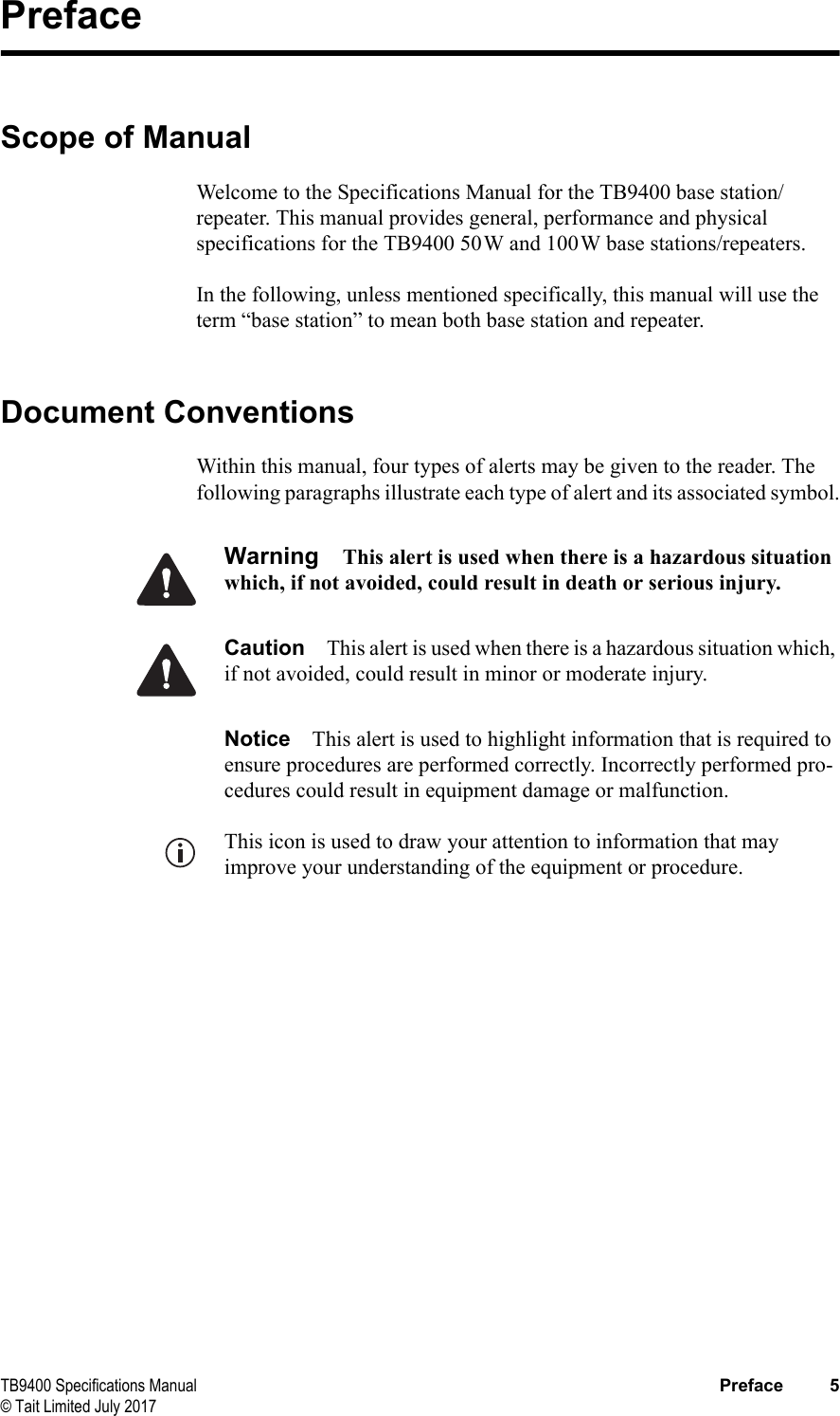
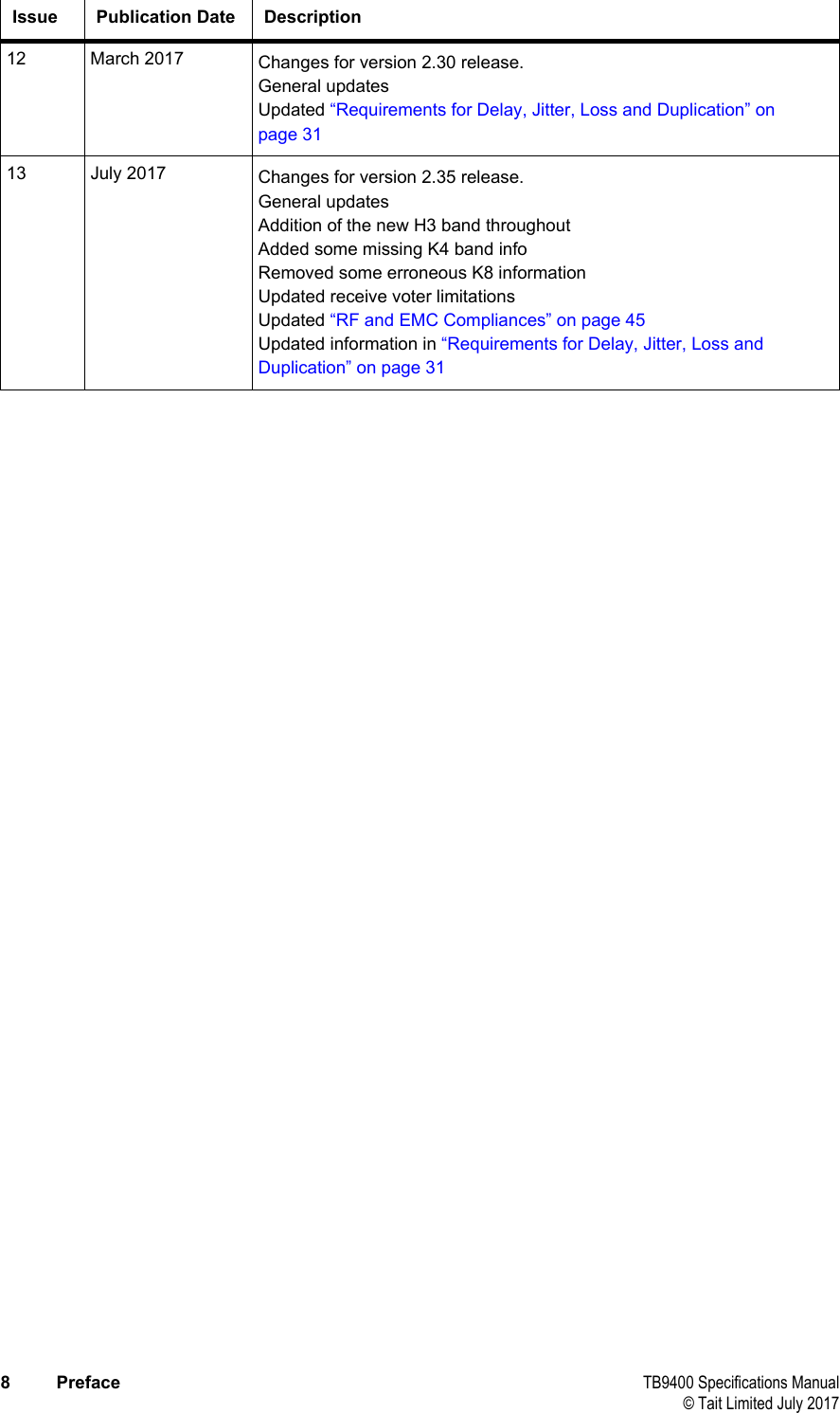
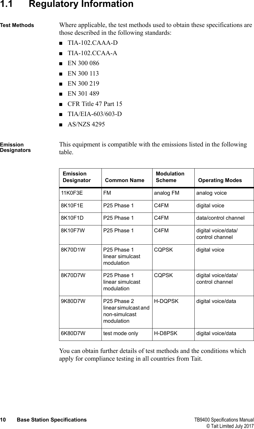
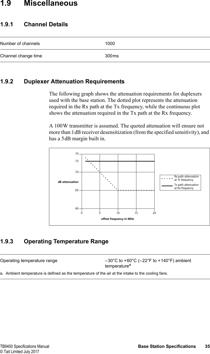
![TB9400 Specifications Manual Base Station Specifications 9© Tait Limited July 20171 Base Station SpecificationsThe performance figures given in these specifications are applicable only to equipment operating as an integral part of a TB9400 base station. These performance figures are minimum figures, unless otherwise indicated, for equipment operating at standard room temperature (+22°C to +28°C [+71.6°F to +82.4°F]) and standard test voltages as follows:■AC power management unit (PMU) - 120VAC and 230VAC■12V DC PMU - 12VDC■24V DC PMU - 24VDC■48V DC PMU - 48VDC. The TB9400 is available in the following configurations:■50W single or dual base station with PMU■100W single base station with PMU■receive-only base station - up to four receivers (receive-only reciters) with PMU.Notice The software release notes list known issues or limitations of the base station that may vary from the specifications published in this document. Please refer to the current software release notes for any vari-ations to the specifications in this document.](https://usermanual.wiki/Tait/TBCH3X/User-Guide-3640136-Page-9.png)