Tait TBCH3X Receive Only Base Station with Ethernet Port User Manual TB9400 Specifications Manual
Tait Limited Receive Only Base Station with Ethernet Port TB9400 Specifications Manual
Tait >
Exhibit D Users Manual per 2 1033 b3

TB9400 Base Station/Repeater
Specifications Manual
MBC-00002-13 · Issue 13 · July 2017

2TB9400 Specifications Manual
© Tait Limited July 2017
Contact Information
Tait Communications
Corporate Head Office
Tait Limited
P.O. Box 1645
Christchurch
New Zealand
For the address and telephone number of regional
offices, refer to our website: www.taitradio.com
Copyright and Trademarks
All information contained in this document is the
property of Tait Limited. All rights reserved.
This document may not, in whole or in part, be copied,
photocopied, reproduced, translated, stored, or reduced
to any electronic medium or machine-readable form,
without prior written permission from Tait Limited.
The word TAIT and the TAIT logo are trademarks of
Tait Limited.
All trade names referenced are the service mark,
trademark or registered trademark of the respective
manufacturers.
Disclaimer
There are no warranties extended or granted by this
document. Tait Limited accepts no responsibility for
damage arising from use of the information contained
in the document or of the equipment and software it
describes. It is the responsibility of the user to ensure
that use of such information, equipment and software
complies with the laws, rules and regulations of the
applicable jurisdictions.
Enquiries and Comments
If you have any enquiries regarding this document, or
any comments, suggestions and notifications of errors,
please contact your regional Tait office.
Updates of Manual and Equipment
In the interests of improving the performance,
reliability or servicing of the equipment, Tait Limited
reserves the right to update the equipment or this
document or both without prior notice.
Intellectual Property Rights
This product may also be made under license under one
or more of the following patents:
- US7203207, AU2004246135, CA2527142,
GB2418107, HK1082608, MY134526, US8306071
- US7339917, AU2004246136, CA2526926,
GB2418812, MY134217
- US7499441, AU2005262626, CA2570441,
GB2430333, JP4690397, NZ551231, KR100869043,
RU2351080, BRP10512052, MXPA06015241
- US 7200129, AU2005226531, CA2558551,
CN1930809, GB2429378, JP4351720, BRP10508671,
NZ549124, KR848483, RU2321952
Environmental Responsibilities
Tait Limited is an environmentally
responsible company which supports
waste minimization, material recovery and
restrictions in the use of hazardous
materials.
The European Union’s Waste Electrical and Electronic
Equipment (WEEE) Directive requires that this
product be disposed of separately from the general
waste stream when its service life is over. For more
information about how to dispose of your unwanted
Tait product, visit the Tait WEEE website at
www.taitradio.com/weee. Please be environmentally
responsible and dispose through the original supplier,
or contact Tait Limited.
Tait Limited also complies with the Restriction of the
Use of Certain Hazardous Substances in Electrical and
Electronic Equipment (RoHS) Directive in the
European Union.
In China, we comply with the Measures for
Administration of the Pollution Control of Electronic
Information Products. We will comply with
environmental requirements in other markets as they
are introduced.

TB9400 Specifications Manual Contents 3
© Tait Limited July 2017
Contents
Preface . . . . . . . . . . . . . . . . . . . . . . . . . . . . . . . . . . . . . . . . . . . . . . . . . . . . . . . . . . . . . . . . . . . . . 5
Scope of Manual . . . . . . . . . . . . . . . . . . . . . . . . . . . . . . . . . . . . . . . . . . . . . . . . . . . . . . . . . . 5
Document Conventions . . . . . . . . . . . . . . . . . . . . . . . . . . . . . . . . . . . . . . . . . . . . . . . . . . . . . 5
Associated Documentation . . . . . . . . . . . . . . . . . . . . . . . . . . . . . . . . . . . . . . . . . . . . . . . . . . 6
Publication Record . . . . . . . . . . . . . . . . . . . . . . . . . . . . . . . . . . . . . . . . . . . . . . . . . . . . . . . . 6
1 Base Station Specifications . . . . . . . . . . . . . . . . . . . . . . . . . . . . . . . . . . . . . . . . . . . . . . . . . 9
1.1 Regulatory Information . . . . . . . . . . . . . . . . . . . . . . . . . . . . . . . . . . . . . . . . . . . . . . . . 10
1.2 Frequency Bands and Sub-bands . . . . . . . . . . . . . . . . . . . . . . . . . . . . . . . . . . . . . . . . .11
1.3 Power Supply . . . . . . . . . . . . . . . . . . . . . . . . . . . . . . . . . . . . . . . . . . . . . . . . . . . . . . . 12
AC Input . . . . . . . . . . . . . . . . . . . . . . . . . . . . . . . . . . . . . . . . . . . . . . . . . . . . . 12
DC Input . . . . . . . . . . . . . . . . . . . . . . . . . . . . . . . . . . . . . . . . . . . . . . . . . . . . . 13
Outputs . . . . . . . . . . . . . . . . . . . . . . . . . . . . . . . . . . . . . . . . . . . . . . . . . . . . . . 14
Auxiliary Power Supply . . . . . . . . . . . . . . . . . . . . . . . . . . . . . . . . . . . . . . . . . 14
1.4 Power and Current Consumption . . . . . . . . . . . . . . . . . . . . . . . . . . . . . . . . . . . . . . . . 15
1.4.1 120VAC Input. . . . . . . . . . . . . . . . . . . . . . . . . . . . . . . . . . . . . . . . . . . . . . . . . 16
Transmit . . . . . . . . . . . . . . . . . . . . . . . . . . . . . . . . . . . . . . . . . . . . . . . . . . . . . 16
Standby . . . . . . . . . . . . . . . . . . . . . . . . . . . . . . . . . . . . . . . . . . . . . . . . . . . . . . 16
1.4.2 230VAC Input. . . . . . . . . . . . . . . . . . . . . . . . . . . . . . . . . . . . . . . . . . . . . . . . . 17
Transmit . . . . . . . . . . . . . . . . . . . . . . . . . . . . . . . . . . . . . . . . . . . . . . . . . . . . . 17
Standby . . . . . . . . . . . . . . . . . . . . . . . . . . . . . . . . . . . . . . . . . . . . . . . . . . . . . . 17
1.4.3 12VDC Input . . . . . . . . . . . . . . . . . . . . . . . . . . . . . . . . . . . . . . . . . . . . . . . . . 18
Transmit . . . . . . . . . . . . . . . . . . . . . . . . . . . . . . . . . . . . . . . . . . . . . . . . . . . . . 18
Standby . . . . . . . . . . . . . . . . . . . . . . . . . . . . . . . . . . . . . . . . . . . . . . . . . . . . . . 18
1.4.4 24VDC Input . . . . . . . . . . . . . . . . . . . . . . . . . . . . . . . . . . . . . . . . . . . . . . . . . 19
Transmit . . . . . . . . . . . . . . . . . . . . . . . . . . . . . . . . . . . . . . . . . . . . . . . . . . . . . 19
Standby . . . . . . . . . . . . . . . . . . . . . . . . . . . . . . . . . . . . . . . . . . . . . . . . . . . . . . 19
1.4.5 48VDC Input . . . . . . . . . . . . . . . . . . . . . . . . . . . . . . . . . . . . . . . . . . . . . . . . . 20
Transmit . . . . . . . . . . . . . . . . . . . . . . . . . . . . . . . . . . . . . . . . . . . . . . . . . . . . . 20
Standby . . . . . . . . . . . . . . . . . . . . . . . . . . . . . . . . . . . . . . . . . . . . . . . . . . . . . . 20
1.5 Receiver. . . . . . . . . . . . . . . . . . . . . . . . . . . . . . . . . . . . . . . . . . . . . . . . . . . . . . . . . . . . 21
General . . . . . . . . . . . . . . . . . . . . . . . . . . . . . . . . . . . . . . . . . . . . . . . . . . . . . . 21
Digital RF . . . . . . . . . . . . . . . . . . . . . . . . . . . . . . . . . . . . . . . . . . . . . . . . . . . . 22
Analog RF. . . . . . . . . . . . . . . . . . . . . . . . . . . . . . . . . . . . . . . . . . . . . . . . . . . . 23
Analog Audio - General . . . . . . . . . . . . . . . . . . . . . . . . . . . . . . . . . . . . . . . . . 25
Analog Audio - CTCSS . . . . . . . . . . . . . . . . . . . . . . . . . . . . . . . . . . . . . . . . . 25
Analog Audio - Gating Operation. . . . . . . . . . . . . . . . . . . . . . . . . . . . . . . . . . 25
1.6 Transmitter . . . . . . . . . . . . . . . . . . . . . . . . . . . . . . . . . . . . . . . . . . . . . . . . . . . . . . . . . 26
General . . . . . . . . . . . . . . . . . . . . . . . . . . . . . . . . . . . . . . . . . . . . . . . . . . . . . . 26
Simulcast. . . . . . . . . . . . . . . . . . . . . . . . . . . . . . . . . . . . . . . . . . . . . . . . . . . . . 28
Analog Audio - General . . . . . . . . . . . . . . . . . . . . . . . . . . . . . . . . . . . . . . . . . 29
Analog Audio - Modulation Characteristics. . . . . . . . . . . . . . . . . . . . . . . . . . 29
4 Contents TB9400 Specifications Manual
© Tait Limited July 2017
Analog Audio - CTCSS . . . . . . . . . . . . . . . . . . . . . . . . . . . . . . . . . . . . . . . . . 30
1.7 Network . . . . . . . . . . . . . . . . . . . . . . . . . . . . . . . . . . . . . . . . . . . . . . . . . . . . . . . . . . . . 31
1.7.1 Requirements for Delay, Jitter, Loss and Duplication. . . . . . . . . . . . . . . . . . . 31
1.7.2 Channel Group Size . . . . . . . . . . . . . . . . . . . . . . . . . . . . . . . . . . . . . . . . . . . . 32
1.8 System Connections . . . . . . . . . . . . . . . . . . . . . . . . . . . . . . . . . . . . . . . . . . . . . . . . . . 33
1.8.1 External Frequency Reference Input (BNC). . . . . . . . . . . . . . . . . . . . . . . . . . 33
1.8.2 Ethernet Interface (RJ45) . . . . . . . . . . . . . . . . . . . . . . . . . . . . . . . . . . . . . . . . 33
1.8.3 System Interface 25-Way D-range . . . . . . . . . . . . . . . . . . . . . . . . . . . . . . . . . 33
External General Purpose Digital Inputs. . . . . . . . . . . . . . . . . . . . . . . . . . . . . 33
1.8.4 1PPS Timing Reference Input (BNC). . . . . . . . . . . . . . . . . . . . . . . . . . . . . . . 34
1.9 Miscellaneous . . . . . . . . . . . . . . . . . . . . . . . . . . . . . . . . . . . . . . . . . . . . . . . . . . . . . . . 35
1.9.1 Channel Details . . . . . . . . . . . . . . . . . . . . . . . . . . . . . . . . . . . . . . . . . . . . . . . . 35
1.9.2 Duplexer Attenuation Requirements. . . . . . . . . . . . . . . . . . . . . . . . . . . . . . . . 35
1.9.3 Operating Temperature Range . . . . . . . . . . . . . . . . . . . . . . . . . . . . . . . . . . . . 35
1.9.4 Heat Load Values . . . . . . . . . . . . . . . . . . . . . . . . . . . . . . . . . . . . . . . . . . . . . . 36
1.9.5 Dimensions and Weight . . . . . . . . . . . . . . . . . . . . . . . . . . . . . . . . . . . . . . . . . 36
1.9.6 Reliability . . . . . . . . . . . . . . . . . . . . . . . . . . . . . . . . . . . . . . . . . . . . . . . . . . . . 36
2 Module Specifications . . . . . . . . . . . . . . . . . . . . . . . . . . . . . . . . . . . . . . . . . . . . . . . . . . . . 37
2.1 Reciter and Receiver . . . . . . . . . . . . . . . . . . . . . . . . . . . . . . . . . . . . . . . . . . . . . . . . . . 38
2.1.1 Identifying the Reciter and Receiver. . . . . . . . . . . . . . . . . . . . . . . . . . . . . . . . 38
2.1.2 Physical Details. . . . . . . . . . . . . . . . . . . . . . . . . . . . . . . . . . . . . . . . . . . . . . . . 39
2.2 PA . . . . . . . . . . . . . . . . . . . . . . . . . . . . . . . . . . . . . . . . . . . . . . . . . . . . . . . . . . . . . . . . 40
2.2.1 Identifying the PA . . . . . . . . . . . . . . . . . . . . . . . . . . . . . . . . . . . . . . . . . . . . . . 40
2.2.2 Physical Details. . . . . . . . . . . . . . . . . . . . . . . . . . . . . . . . . . . . . . . . . . . . . . . . 41
2.3 PMU. . . . . . . . . . . . . . . . . . . . . . . . . . . . . . . . . . . . . . . . . . . . . . . . . . . . . . . . . . . . . . . 42
2.3.1 Identifying the PMU . . . . . . . . . . . . . . . . . . . . . . . . . . . . . . . . . . . . . . . . . . . . 42
2.3.2 Physical Details. . . . . . . . . . . . . . . . . . . . . . . . . . . . . . . . . . . . . . . . . . . . . . . . 43
2.3.3 Connections. . . . . . . . . . . . . . . . . . . . . . . . . . . . . . . . . . . . . . . . . . . . . . . . . . . 43
3 Compliance Standards. . . . . . . . . . . . . . . . . . . . . . . . . . . . . . . . . . . . . . . . . . . . . . . . . . . . 44
Appendix A – Frequency Response Diagrams . . . . . . . . . . . . . . . . . . . . . . . . . . . . . . . . . . . . 47
TB9400 Specifications Manual Preface 5
© Tait Limited July 2017
Preface
Scope of Manual
Welcome to the Specifications Manual for the TB9400 base station/
repeater. This manual provides general, performance and physical
specifications for the TB9400 50W and 100W base stations/repeaters.
In the following, unless mentioned specifically, this manual will use the
term “base station” to mean both base station and repeater.
Document Conventions
Within this manual, four types of alerts may be given to the reader. The
following paragraphs illustrate each type of alert and its associated symbol.
Warning This alert is used when there is a hazardous situation
which, if not avoided, could result in death or serious injury.
Caution This alert is used when there is a hazardous situation which,
if not avoided, could result in minor or moderate injury.
Notice This alert is used to highlight information that is required to
ensure procedures are performed correctly. Incorrectly performed pro-
cedures could result in equipment damage or malfunction.
This icon is used to draw your attention to information that may
improve your understanding of the equipment or procedure.

6 Preface TB9400 Specifications Manual
© Tait Limited July 2017
Associated Documentation
The following associated documentation for this product is available on the
Tait support website.
■TB9400 Installation and Operation Manual (MBC-00001-xx)
■TN9400 P25 Trunked Network Maintenance Manual (MNC-00001-xx)
■TaitNet P25 Trunked Networks with TB9400 Base Stations System
Manual (MBA-00064-xx)
■TaitNet Analog Conventional Networks with TB9400 Base Stations
System Manual (MND-00001-xx)
■Safety and Compliance Information (MBA-00012-xx)
The characters xx represent the issue number of the documentation.
Technical notes are published from time to time to describe applications for
Tait products, to provide technical details not included in manuals, and to
offer solutions for any problems that arise. Technical notes are available in
PDF format from the Tait support website. For more information contact
your regional Tait office.
Publication Record
Issue Publication Date Description
1 May 2012 First release
2 November 2012 Changes for version 1.15 release.
Additions
■operating temperature range
■Btu load values
Updates
■power and current consumption
■compliance standards
3 June 2013 Changes for version 1.20 release.
Additions
■B3-band base station specifications
Updates
■compliance standards
4 November 2013 Changes for version 1.30 release.
Additions
■H-band base station specifications
■Dual 50W and receive-only base station specifications
Updates
■compliance standards

TB9400 Specifications Manual Preface 7
© Tait Limited July 2017
5 December 2014 Changes for version 1.45 release.
Additions
■K4 band receive-only base station specifications
■P25 Phase 2 specifications
Updates
■P25 Phase 2 emission designators
■compliance standards
6 April 2015 Changes for version 2.00 release.
Additions
■K4 band 50W base station specifications
■peak-to-average power level specifications
Updates
■base station MTBF
■compliance standards
7 July 2015 Changes for version 2.05 release.
Additions
■information on receive-only base stations and receiver modules
■1PPS jitter specification
Updates
■external frequency reference stability specification
■compliance standards
8 November 2015 Changes for version 2.10 release.
Additions
■information on analog base stations
Updates
■compliance standards
9 April 2016 Changes for version 2.15 release.
Additions
■Clarification of repeater vs. base station for K and L bands in Brazil
10 June 2016 Changes for version 2.20 release.
Additions
■table added to section 1.5 Analog RF specifying that the TB9400 only
supports Narrow Bandwidth
■inclusion of B band alongside G and F
11 November 2016 Changes for version 2.25 release.
Additions
■General updates.
■Information added in regards to the QoS requirements (delay, jitter,
loss, duplication).
■Fix Anatel approvals
Issue Publication Date Description

8 Preface TB9400 Specifications Manual
© Tait Limited July 2017
12 March 2017 Changes for version 2.30 release.
General updates
Updated “Requirements for Delay, Jitter, Loss and Duplication” on
page 31
13 July 2017 Changes for version 2.35 release.
General updates
Addition of the new H3 band throughout
Added some missing K4 band info
Removed some erroneous K8 information
Updated receive voter limitations
Updated “RF and EMC Compliances” on page 45
Updated information in “Requirements for Delay, Jitter, Loss and
Duplication” on page 31
Issue Publication Date Description

TB9400 Specifications Manual Base Station Specifications 9
© Tait Limited July 2017
1 Base Station Specifications
The performance figures given in these specifications are applicable only
to equipment operating as an integral part of a TB9400 base station. These
performance figures are minimum figures, unless otherwise indicated, for
equipment operating at standard room temperature (+22°C to +28°C
[+71.6°F to +82.4°F]) and standard test voltages as follows:
■AC power management unit (PMU) - 120VAC and 230VAC
■12V DC PMU - 12VDC
■24V DC PMU - 24VDC
■48V DC PMU - 48VDC.
The TB9400 is available in the following configurations:
■50W single or dual base station with PMU
■100W single base station with PMU
■receive-only base station - up to four receivers (receive-only reciters)
with PMU.
Notice The software release notes list known issues or limitations of
the base station that may vary from the specifications published in this
document. Please refer to the current software release notes for any vari-
ations to the specifications in this document.

10 Base Station Specifications TB9400 Specifications Manual
© Tait Limited July 2017
1.1 Regulatory Information
Test Methods Where applicable, the test methods used to obtain these specifications are
those described in the following standards:
■TIA-102.CAAA-D
■TIA-102.CCAA-A
■EN 300 086
■EN 300 113
■EN 300 219
■EN 301 489
■CFR Title 47 Part 15
■TIA/EIA-603/603-D
■AS/NZS 4295
Emission
Designators
This equipment is compatible with the emissions listed in the following
table.
You can obtain further details of test methods and the conditions which
apply for compliance testing in all countries from Tait.
Emission
Designator Common Name
Modulation
Scheme Operating Modes
11K0F3E FM analog FM analog voice
8K10F1E P25 Phase 1 C4FM digital voice
8K10F1D P25 Phase 1 C4FM data/control channel
8K10F7W P25 Phase 1 C4FM digital voice/data/
control channel
8K70D1W P25 Phase 1
linear simulcast
modulation
CQPSK digital voice
8K70D7W P25 Phase 1
linear simulcast
modulation
CQPSK digital voice/data/
control channel
9K80D7W P25 Phase 2
linear simulcast and
non-simulcast
modulation
H-DQPSK digital voice/data
6K80D7W test mode only H-D8PSK digital voice/data

TB9400 Specifications Manual Base Station Specifications 11
© Tait Limited July 2017
1.2 Frequency Bands and Sub-bands
Many of the performance figures in this manual are applicable to all
frequency bands. In some cases the figures refer to specific bands or sub-
bands, and these are identified with the letters listed in the following table.
The table also indicates which base station configurations are currently
available in each frequency band.
Refer to “Compliance Standards” on page 44 for details about which bands
or sub-bands have been tested and approved to appropriate national and
international compliance standards.
In Brazil, for K band, the TB9400 is considered to be configured as a base
station with retransmission of receive frequencies.
Frequency
Identification Frequency Band and Sub-band 50W 100W Receive-only
B band B3 = 148MHz to 174MHz ✓✓ ✓
H band H1 = 400MHz to 440MHz
H2 = 440MHz to 480MHz
H3 = 470MHz to 520MHz
✓✓ ✓
K band K4 = 762MHz to 870MHza✓✓ ✓
a. The actual frequency coverage in this band is:
Transmit: 762MHz to 776MHz, and 850MHz to 870MHz
Receive: 792MHz to 824MHz

12 Base Station Specifications TB9400 Specifications Manual
© Tait Limited July 2017
1.3 Power Supply
The specifications in this section refer to the TB9400 base station fitted
with a PMU.
AC Input
Input
Voltage
Frequency
Power factor
Total harmonic distortion (THD)
Inrush current
230VAC
115VAC
Leakage current
88VAC to 264VAC
50Hz to 60Hz
> 0.95
< 8%
< 30A @ < 4ms
< 15A @ < 4ms
< 3.5mA/240VAC
Protection
Fault current (input)
Transient suppression
Overvoltage inhibit (self recovering)
Undervoltage signal
10A fuse
275V MOV (line-to-line)
275VAC ±10V
83VAC ±5V
General
Efficiency at rated outputa
Input-to-chassis isolation
Output-to-chassis isolation
86%
1500VAC, 50Hz, 1 minute
500VAC, 50Hz, 1 minute
a. At 230VAC.

TB9400 Specifications Manual Base Station Specifications 13
© Tait Limited July 2017
DC Input
Input voltage
User-programmable alarmsa
Low battery voltage
High battery voltage
User-programmable limitsb
Startup voltage
(after shutdown)
Shutdown voltage
Battery protection (fail-safe) limitsc
Startup voltage
Undervoltage shutdown
Overvoltage shutdown
Overvoltage shutdown reset
12V PMU
10V to 14V
14V to 17.5V
10.9V to 15V ±0.3V
10V to 13.5V ±0.3V
10.8V ±0.2V
9.5V ±0.3V
18.1V ±0.3V
17.1V ±0.3V
24V PMU
20V to 28V
28V to 35V
21.8V to 30V ±0.5V
20V to 27V ±0.5V
21.6V ±0.5V
19V ±0.5V
36.2V ±0.5V
34.2V ±0.5V
48V PMU
40V to 56V
56V to 70V
43.6V to 60V ±1V
40V to 54V ±1V
43.2V ±1V
38V ±1V
72.4V ±1V
68.4V ±1V
a. User-programmable alarms can be set for low or high battery voltage, using the web interface. The alarms will be triggered
when the set voltage levels are reached. These limits are subject to the tolerances of the battery protection circuitry, as
stated in “Battery Protection (Fail-safe) Limits” above.
b. The user-programmable startup and shutdown limits allow for adjustable startup and shutdown voltages. Using the web
interface, these limits can be adjusted for different numbers of battery cells, or for the particular requirements of the base
station operation. Once the limits are reached, the PMU will shutdown. These limits are subject to the tolerances of the
battery protection circuitry.
c. The battery protection limits are set in hardware at the factory and cannot be adjusted by the user. These limits will not be
reached under normal operation conditions, but are provided as “fail-safe” measures to protect the battery from deep
discharge.
Input current
0V to battery protection startup
voltaged
Battery protection startup voltage to
user-programmed startup voltagee
12V
2mA maximum
40mA typical
at 10.8V
24V
2mA maximum
30.1mA typical
at 21.6V
48V
1.2mA maximum
13.2mA typical
at 43.2V
Operating current refer to “Power and Current Consumption” on page 15
d. When the input voltage drops below the battery protection undervoltage shutdown limit, and until the voltage rises above the
battery protection startup voltage.
e. At initial power-up; or, after battery protection has occurred, when the input voltage rises above the battery protection startup
voltage (PMU now under control of its microcontroller), but is still below the user-programmed startup voltage
Protection
Fault current (input)
Wrong input voltage
Wrong input voltage polarity
circuit breaker or fuse in external wiringf
electronic lock-out
shunt diode
f. Provided by user.
General
Efficiency at rated output
12VDC
24VDC
48VDC
82%
85%
90%

14 Base Station Specifications TB9400 Specifications Manual
© Tait Limited July 2017
Outputs
28VDC output
Voltage
Current
Regulation
Ripple and noisea
Ripple and noise rms
Transient response on 28V loadstepb
28V
14A maximum
±0.5%
50mV pp
10mV rms
2% overshoot and recover within 0.6ms
a. 100MHz bandwidth.
b. 10% to 100% loadstep.
Protection
Overload
Short circuit
Overvoltage
AC module
DC module
electronic current limit above 16A
hiccup mode, self-resetting
electronic shutdown latch (33.5V)
electronic hysteric control (33.5V)
Auxiliary Power Supply
DC input voltage 28V ±15%
DC output
Voltage
Current
Regulation
Ripple and noisea
Ripple and noise rms
Zero load ripple
12V
13.65V
3A maximum
±2%
50mV pp
10mV rms
100mVpp
24V
27.3V
1.5A maximum
±2%
50mV pp
10mV rms
100mVpp
48V
54.6V
750mA maximum
±2%
50mV pp
10mV rms
100mVpp
a. 100MHz bandwidth.
Protection
Overload/short circuit
Overvoltage
12V
electronic
current limit
16V Zener diode
24V
electronic
current limit
32V Zener diode
48V
electronic
current limit
62V Zener diode
General
Efficiency at rated output
Input-to-output isolation
Output-to-chassis isolation
88%
1000VAC, 50Hz, 1 minute
500VAC, 50Hz, 1 minute
TB9400 Specifications Manual Base Station Specifications 15
© Tait Limited July 2017
1.4 Power and Current Consumption
The specifications in this section refer to the TB9400 base station fitted
with a PMU. The performance figures are typical figures.
The transmit measurements were carried out with the base station
transmitting at the stated RF output power with all front panel fans running.
The standby measurements were carried out with the base station not
receiving or transmitting and no front panel fans running. All
measurements were carried out with no load on the auxiliary power supply.

16 Base Station Specifications TB9400 Specifications Manual
© Tait Limited July 2017
1.4.1 120VAC Input
Transmit
AVAW
Single 50W base station
Minimum RF output power (5W)
Maximum RF output power (50W)
1A
1.9A
120VA
238VA
117 W
235W
Dual 50W base stationa
Minimum RF output power (5W)
Maximum RF output power (50W)
1.7A
2A
207VA
450VA
204W
440W
a. Both base stations transmitting.
100W base station
Minimum RF output power (10W)
50% RF output power (50W)
Maximum RF output power (100W)
1.6A
2.4A
3.3A
192VA
295VA
400VA
189W
290W
395W
Standby
AVAW
Single 50W and 100W base station 370mA 44VA 30W
Dual 50W base station 490mA 59VA 50W

TB9400 Specifications Manual Base Station Specifications 17
© Tait Limited July 2017
1.4.2 230VAC Input
Transmit
AVAW
Single 50W base station
Minimum RF output power (5W)
Maximum RF output power (50W)
700mA
1.1A
159VA
250VA
108W
220W
Dual 50W base stationa
Minimum RF output power (5W)
Maximum RF output power (50W)
1A
2A
230VA
460VA
196W
440W
a. Both base stations transmitting.
100W base station
Minimum RF output power (10W)
50% RF output power (50W)
Maximum RF output power (100W)
970mA
1.3A
1.7A
223VA
310VA
395VA
183W
285W
375W
Standby
AVAW
Single 50W and 100W base station 510mA 117VA 31W
Dual 50W base station 510mA 117VA 45W

18 Base Station Specifications TB9400 Specifications Manual
© Tait Limited July 2017
1.4.3 12VDC Input
Transmit
AW
Single 50W base station
Minimum RF output power (5W)
Maximum RF output power (50W)
8.8A
18A
106W
216W
Dual 50W base stationa
Minimum RF output power (5W)
Maximum RF output power (50W)
16A
36A
192W
432W
a. Both base stations transmitting.
100W base station
Minimum RF output power (10W)
50% RF output power (50W)
Maximum RF output power (100W)
14.6A
23.6A
32A
176W
285W
385W
Standby
AW
Single 50W and 100W base station 2.0A 24W
Dual 50W base station 3.3A 39W

TB9400 Specifications Manual Base Station Specifications 19
© Tait Limited July 2017
1.4.4 24VDC Input
Transmit
AW
Single 50W base station
Minimum RF output power (5W)
Maximum RF output power (50W)
4.4A
9A
106W
216W
Dual 50W base stationa
Minimum RF output power (5W)
Maximum RF output power (50W)
7.9A
17A
190W
408W
a. Both base stations transmitting.
100W base station
Minimum RF output power (10W)
50% RF output power (50W)
Maximum RF output power (100W)
7.1A
11.8 A
15.5A
171W
285W
370W
Standby
AW
Single 50W and 100W base station 975mA 23W
Dual 50W base station 1.6A 39W

20 Base Station Specifications TB9400 Specifications Manual
© Tait Limited July 2017
1.4.5 48VDC Input
Transmit
AW
Single 50W base station
Minimum RF output power (5W)
Maximum RF output power (50W)
2.1A
4.2A
101W
202W
Dual 50W base stationa
Minimum RF output power (5W)
Maximum RF output power (50W)
3.7A
7.8A
178W
374W
a. Both base stations transmitting.
100W base station
Minimum RF output power (10W)
50% RF output power (50W)
Maximum RF output power (100W)
3.2A
5.5A
7.4A
155W
265W
355W
Standby
AW
Single 50W and 100W base station 480mA 23W
Dual 50W base station 780mA 38W

TB9400 Specifications Manual Base Station Specifications 21
© Tait Limited July 2017
1.5 Receiver
General
Frequency bands
B3 band
H1 band
H2 band
H3 band
K4 band
148MHz to 174MHz
400MHz to 440MHz
440MHz to 480MHz
470MHz to 520MHz
794MHz to 824MHz
Type triple conversion superheterodyne; first conversion is
analog, second is hybrid, and third is digital
Frequency increments
B band
H and K4 bands
2.5 kHz and 3.125 kHz
5 kHz and 6.25 kHz
Switching rangea
B band
H band and K4 bands
±2 MHz
±5 MHz
a. The frequency range, measured from the tuned frequency, that can be used without needing to retune the front end or
recalibrate the RSSI.
Input load impedance 50Ω nominal (VSWR <2:1)
RF input protection no degradation after 5 minutes exposure to
on-channel signals at +20dBm (2.2V)
Frequency stability
Internal reference
External reference
B band
H band
K band
±0.5ppm –30°C to +60°C (–22°F to +140°F)
±1Hz ± multiplied accuracy of external reference
±1Hz ± multiplied accuracy of external reference
±2Hz ± multiplied accuracy of external reference
RSSI ≤–125dBm to –30dBm
IF stages - B band
Frequencies
Analog
Digital
Analog IF bandwidth
Digital IF bandwidth
16.9MHz
16.9MHz and 0Hz
9kHz, –3dB
8.06kHz, –3dB
IF stages - H and K4 bands
Frequencies
Analog
Digital
Analog IF bandwidth
Digital IF bandwidth
70.1MHz
8.66MHz and 0Hz
9kHz, –3dB
8.06kHz, –3dB

22 Base Station Specifications TB9400 Specifications Manual
© Tait Limited July 2017
Spurious Emissions
Conducted
Radiated
<–90dBm 9kHz to 2GHz
<–70dBm 2GHz to 12.75GHz
<–57dBm 30MHz to 1GHz
<–47dBm 1GHz to 4GHz
General (Continued)
Digital RF
The test methods used to obtain these figures are those described in TIA-102.CAAA-D for P25
Phase 1, and TIA-102.CCAA-A for P25 Phase 2.
Digital unfaded sensitivitya<–120dBm @ 5% BER
Digital faded sensitivitya–112dBm @ 5% BER
a. At 25°C.
Digital adjacent channel rejection 60dB
Digital signal displacement bandwidth 1kHz
Digital spurious response attenuation ≥100dB
Digital intermodulation response attenuation 85dB
Digital blocking rejection
1 to 10MHz 100dB
Digital co-channel rejection 9dB

TB9400 Specifications Manual Base Station Specifications 23
© Tait Limited July 2017
Analog RF
Sensitivitya,b
De-emphasized response
Centre of switching range
Edge of switching range
<–119dBm (0.25μV) at 25°C
<–117dBm (0.32μV) at 25°C
a. 12dB SINAD.
b. Up to 2dB degradation at extremes of temperature.
Maximum usable sensitivityc,d
De-emphasized response
Centre of switching range
Edge of switching range
<–116dBm (0.35μV) at 25°C
<–114dBm (0.45μV) at 25°C
c. Sensitivity for 20dB SINAD, psophometrically weighted, RF source modulated at 60% deviation with 1kHz.
d. Up to 2dB degradation at extremes of temperature.
FM quietinge–113dBm
e. 20dB FM quieting, measured with de-emphasis on.
Ultimate signal-to-noise ratio (at –47dBm)f
B, G and H bands
K4 band
45dB (ANSI/TIA)
50dB (CEPT - psophometric)
43dB (ANSI/TIA)
f. Up to 5dB degradation at extremes of switching range and temperature.
Selectivityg
B, G and H bands
K4 band
g. Up to 5dB degradation at extremes of switching range and temperature.
Signal displacement bandwidth ≥1kHz
Spurious response attenuation ≥100dB (ANSI/TIA)
≥90dB (ETSI)
Channel
Spacing
Modulation 100% Deviation
(Nominal)
Receiver IF
Bandwidth
Narrow Bandwidth (NB) 12.5kHz +/-2.5kHz 7.5kHz
EIA-603 TIA/EIA-603-D ETSI
85dB
79dB
50dB
45dB
85dB
––

24 Base Station Specifications TB9400 Specifications Manual
© Tait Limited July 2017
Intermodulation response attenuationh
B, G and H bands
K4 band
80dB (ETSI)
80dB (ANSI/TIA)
h. Up to 5dB degradation at extremes of switching range and temperature.
Blocking rejection
B, G and H bands
1–10MHz
>10MHz
±1, ±2, ±5 and ±10MHz
K4 band
1–10MHz
>10MHz
±1, ±2, ±5 and ±10MHz
100dB (ETSI)
110 dB (ETSI)
100dB (ANSI/TIA)
100dB (ANSI/TIA)
110dB (ANSI/TIA)
100dB (ANSI/TIA)
Co-channel rejection –8dB
Amplitude characteristici≤3dB (ETSI)
i. RF Input Level –107dBm to –13dBm.
Analog RF (Continued)

TB9400 Specifications Manual Base Station Specifications 25
© Tait Limited July 2017
Analog Audio - General
Frequency response de-emphasized (750μs)
For more information refer to “Appendix A –
Frequency Response Diagrams” on page 47.
De-emphasized response
Bandwidth
Response
300Hz to 3kHz
within +1, –3dB of a –6dB/octave de-emphasis
curve (ref. 1kHz)
Analog Audio - CTCSS
High pass (subaudible) filter
Bandwidth
Response
Hum and noisea
300Hz to 3kHz
within +1, –3dB of a –6dB/octave de-emphasis
curve (ref. 1kHz)
30dB minimum at 250.3Hz
35dB typical (67Hz to 240Hz)
a. 1kHz at 60% system deviation, CTCSS at 10% system deviation.
Tone detect
Tone squelch opening better than 6dB SINAD
Tone detect bandwidth
Accept
Reject
Response time
(open)
±2Hz typical
±3.6Hz typical
≤150ms typical
Analog Audio - Gating Operation
SINAD gating
Opening level
Accuracy
RF hysteresis
Opening time
Closing time
6dB to 20dB SINAD
±3dB
4dB
60ms typical
60ms typical

26 Base Station Specifications TB9400 Specifications Manual
© Tait Limited July 2017
1.6 Transmitter
The specifications in this section pertain only to the combination of a
TB9400 reciter with a 50W or 100W power amplifier.
General
Frequency bands
B3 band
H1 band
H2 band
H3 band
K4 band
148MHz to 174MHz
400MHz to 440MHz
440MHz to 480MHz
470MHz to 520MHz
762MHz to 776MHz and 850MHz to 870MHz
Modulation types 11K0F3E, 8K10F1E, 8K10F1D, 8K10F7W,
8K70D1W, 8K70D7W, 9K80D7W, 6K80D7W
Frequency increments
B3 band
H and K4 bands
2.5kHz and 3.125kHz
5kHz and 6.25kHz
Frequency stabilitya±0.5ppm –30°C to +60°C (–22°F to +140°F)
a. For K4 band (762MHz to 776MHz) the internal frequency reference accuracy is inadequate, and an external
reference must be used. The stability of this reference should be better than 100 parts per billion. See “External
Frequency Reference Input (BNC)” on page 33.
Output load impedance 50Ω nominal
Output power
50W PA
Rated Power
Range of Adjustment
100W PA
Rated power
Range of adjustment
50W
5W to 50W in 1W steps
100W
10W to 100W in 1W steps
Output power accuracyb
Within normal operating voltages and
temperatures
At extremes of temperature and altitude
+0.5/–0dB into a 50Ω load
+0.5/–1.5dB into a 50Ω load
b. Measured directly on PA output.
Peak-to-average power levelcpeak power is +2.7dB above average rated power
c. LSM and P25 Phase 2 only.

TB9400 Specifications Manual Base Station Specifications 27
© Tait Limited July 2017
Duty cycle
Up to 3600m (11810ft) altitude
Above 3600m (11810ft) altitude
100% at maximum rated output powerd at +60°C
(+140°F) ambient temperature
100% at maximum rated output powerd at +50°C
(+122°F) ambient temperature, or output power
derated by 1.5dB at +60°C (+140°F)
d. Measured directly on PA output.
Mismatch capability
Ruggedness
Stability
open and short circuit load at any phase angle for one
houre
5:1 load VSWR at all phase anglese
e. Under power foldback.
Protectionf
Temperature
Current
Supply voltage
VSWR
Feedback loop instability
power foldback to 35W if RF power devices exceed
safe operating conditions
power foldback and shutdown if RF power devices
exceed safe operating currents for more than 5
seconds
power foldback to 35W when supply voltage is 24V to
26V and 30V to 32V; shutdown when supply voltage
is <24V and >32V
power foldback to 35W when VSWR >3:1
power reduces to maintain loop stability within safe
margins
f. Power foldback to 35W occurs only if the output power is set to more than 35W. If the output power is set to less than
35W, the power stays at the set level during foldback conditions.
Adjacent channel powerg
All modulation types < –67dBc TIA-102.CAAA and TIA-102.CCAA
Adjacent channel power (B3 and H bands only)
All modulation types < –60dBc EN 300 113
g. 762-776MHz band complies with FCC 47 CFR 27.53(e)(6) and 47 CFR 90.543(a)
Modulation emission spectrum TIA-102.CAAB-D paragraphs 3.2.5.1 and 3.2.5.2,
LSM, and TIA-102.CCAB paragraph 3.2.5.1
Modulation fidelity <2% TIA-102.CAAA and TIA-102.CCAA
Intermodulation better than 65dB TIA-102.CAAA and TIA-102.CCAA
(typical)
General (Continued)

28 Base Station Specifications TB9400 Specifications Manual
© Tait Limited July 2017
Sideband noiseh
±12.5 κΗζ
±100kHz
≥±1.5MHz
< –120dBc/Hz
< –130dBc/Hz
< –154dBc/Hz at 50W
< –157dBc/Hz at 100W
h. No modulation, measured from center frequency.
Radiated spurious emissions
Transmit - B3 band
Transmit - H band
Transmit - K4 band
Standby
< –36dBm 30 MHz to 1GHz
< –30dBm 1GHz to 4GHz
< –36dBm 30MHz to 1GHz
< –30dBm 1GHz to 4GHzi
< –30dBm 1GHz to 12.75GHzj
<–20dBm to 9GHz
<–57dBm to 1GHz
<–47dBm 1GHz to 4GHz
i. Transmit frequency below 470MHz.
j. Transmit frequency above 470MHz.
Conducted spurious emissions
Transmit - B3 band
Transmit - H band
Transmit - K4 band
Standby
< –36dBm 9 kHz to 1GHz
< –30dBm 1GHz to 4GHz
< –36dBm 30MHz to 1GHz
< –30dBm 1GHz to 4GHzk
< –30dBm 1GHz to 12.75GHzl
<–20dBm to 9GHz
<–57dBm to 1GHz
<–47dBm 1GHz to 12.75GHz
k. Transmit frequency below 470MHz.
l. Transmit frequency above 470MHz.
Transient behavior - B3 and H bands complies with EN 300 113-1 v1.7.1 and EN 300 113-2
v1.5.1
General (Continued)
Simulcast
Launch time accuracya±1.5µs
a. Launch time offset adjustable in 1µs increments.
Deviation accuracy 0.2dB
Frequency accuracyb<1Hz
b. Carrier frequency offset adjustable in 0.1Hz increments.

TB9400 Specifications Manual Base Station Specifications 29
© Tait Limited July 2017
Supported simulcast modulation schemes
P25
Analog
C4FM
LSM
H-DQPSK
FM
Receive voter limitationsc
Maximum number of receivers
Maximum marshaling duration:
P25
Analog
Maximum central voter speech packet
arrival time skew
20
300ms (simulcast operation)
150ms (simulcast operation)
100ms
c. For a discussion of the significance of these limitations, see the System Manual.
Simulcast (Continued)
Analog Audio - General
Peak deviation ≤2.5kHz
Limiting deviationa≥90% of peak deviation for the configured
bandwidth
a. With modulation input driven at a frequency of 1kHz, and at a level 20dB above the nominal level of 60% deviation.
Nominal deviation (average)b55% to 65% of peak deviation
b. For a level of –10dBm0 applied to the G.711/IP input.
CWID deviation 40% of peak deviation
Analog Audio - Modulation Characteristics
Frequency response (below limiting) flat or pre-emphasized
For more information refer to “Appendix A –
Frequency Response Diagrams” on page 47.
G.711 inputs
Pre-emphasised response
Bandwidth
Below limiting
Flat response
Bandwidth
Response
300Hz to 3kHz
within +1, –3dB of a 6dB/octave pre-emphasis curve
(ref. 1kHz)
300Hz to 3kHz
within +0.5, –1.5dB of output level at 1kHz

30 Base Station Specifications TB9400 Specifications Manual
© Tait Limited July 2017
Above limiting response within +1, –2dB of a flat response (ref. 1kHz)
Distortion <2%
Hum and noisec–50dB typical (ETSI)
c. Up to 5dB degradation at extremes of switching range and temperature.
Analog Audio - Modulation Characteristics (Continued)
Analog Audio - CTCSS
Standard tones all 37 ANSI/TIA group A, B and C tones plus 13
commonly used tones
Frequency error (from ANSI/TIA tones) 0.08% maximum
Generated tone distortion 1.2% maximum
Generated tone flatness flat across 67Hz to 250.3Hz to within 1dB
Modulation level Adjustable
Modulated distortion <5%

TB9400 Specifications Manual Base Station Specifications 31
© Tait Limited July 2017
1.7 Network
1.7.1 Requirements for Delay, Jitter, Loss and Duplication
Standard Requirements Recommended Required
Out of order C plane and U plane packetsaLess than 0.01%
Packet Loss Less than 0.01%
Latency Less than 40 ms < 150 ms
Jitter Less than 20 ms < 100 ms
Skew Less than 80 ms
Minimum bandwidth to carry C+U traffic 108kb/s per physical channel
Minimum bandwidth to carry M traffic 100kb/s per site
Minimum bandwidth to meet jitter requirements on
non-fragmenting link.
600kb/s per site up to 5 physical
channels
a. C plane and U plane are references to telco terminology distinguishing call setup and user traffic.

32 Base Station Specifications TB9400 Specifications Manual
© Tait Limited July 2017
1.7.2 Channel Group Size
‘Channel group size’ is the number of members (transceivers or receivers)
in a channel group.
‘Vote contributors’ are the number of active receivers that will contribute
to the voted output. When a channel group has more than 14 vote
contributors, the channel group enables an automatic 10 contributor limit
on the current streams in order to maintain an acceptable responsiveness to
management functions such as the web user interface.
The table below defines vote contributors and channel group size for each
channel type:
Channel type Vote
contributors
Channel group
size
Analog 14a / 10b
a. When channel group size is less than or equal to 14.
b. When channel group size is greater than 14.
20
P25 Failsoft 14 14
P25 Trunked Control Channel 14 14
P25 Trunked Traffic Channel Phase 1 14 14
P25 Trunked Traffic Channel Phase 2 14 14
P25 Conventional 14a / 10b20

TB9400 Specifications Manual Base Station Specifications 33
© Tait Limited July 2017
1.8 System Connections
1.8.1 External Frequency Reference Input (BNC)
1.8.2 Ethernet Interface (RJ45)
1.8.3 System Interface 25-Way D-range
Frequenciesa10MHz or 12.8MHz
Lock range ±50Hz
Input level 500mVpp to 5Vpp
Input impedance ≥1kΩ
a. Automatically detected by the reciter.
Transceiver 10/100 Base-Tx/Rx (Auto-MDIX)
IEEE-spec IEEE802.3 and 802.3u
External General Purpose Digital Inputs
Input low threshold VIL <0.6V
Input high threshold VIH >1.2V
Input source current IIL <1mA (VIL = 0V)
Continuous input voltage |VIN| <30V
Transient input voltage |VIN| <35V (t <1s)

34 Base Station Specifications TB9400 Specifications Manual
© Tait Limited July 2017
1.8.4 1PPS Timing Reference Input (BNC)
Input low threshold VIL <0.6V
Input high threshold VIH >1.2V
Input termination 470Ω + 5% (AC terminated)
Transient input voltage |VIN| <15V
Frequency 1PPS (required for Simulcast and TDMA)
Polarity rising edge represents timing reference
Maximum jitter ±1µS
TB9400 Specifications Manual Base Station Specifications 35
© Tait Limited July 2017
1.9 Miscellaneous
1.9.1 Channel Details
1.9.2 Duplexer Attenuation Requirements
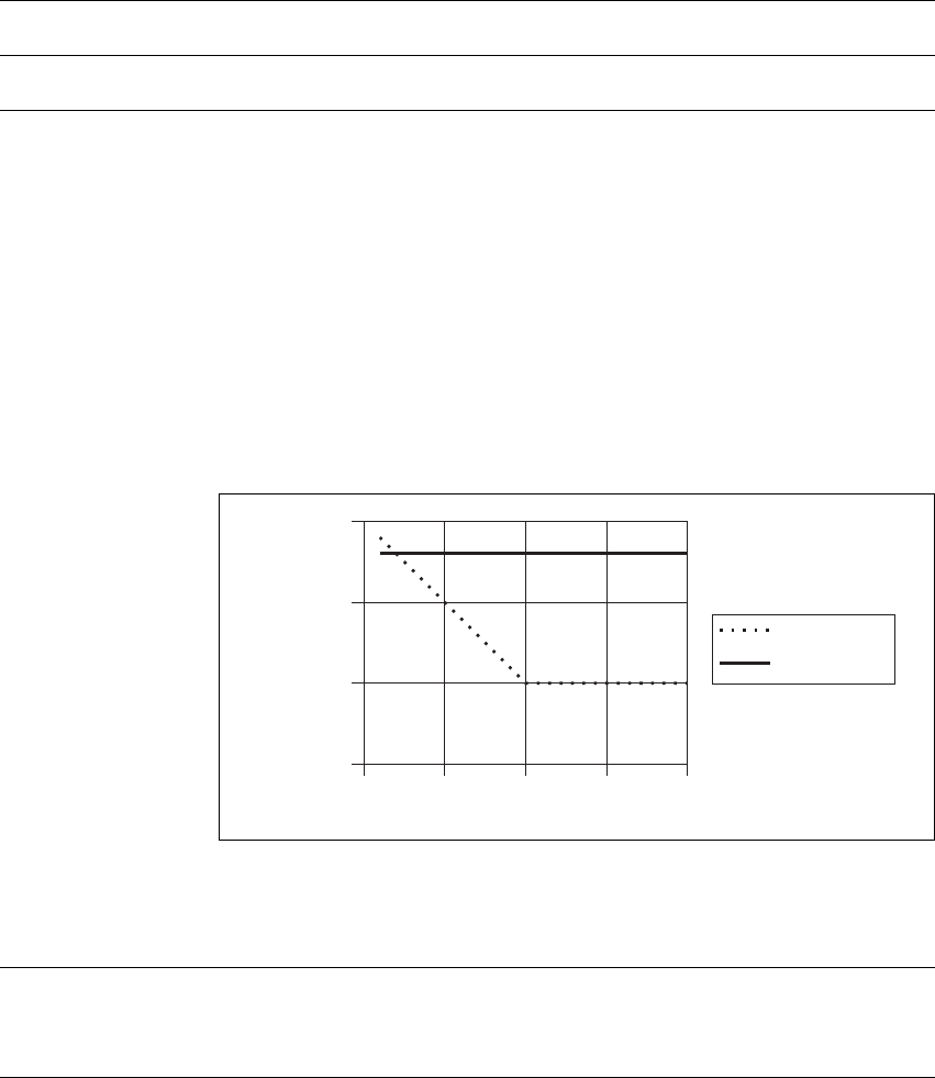
The following graph shows the attenuation requirements for duplexers
used with the base station. The dotted plot represents the attenuation
required in the Rx path at the Tx frequency, while the continuous plot
shows the attenuation required in the Tx path at the Rx frequency.
A 100W transmitter is assumed. The quoted attenuation will ensure not
more than 1dB receiver desensitization (from the specified sensitivity), and
has a 5dB margin built in.
1.9.3 Operating Temperature Range
Number of channels 1000
Channel change time 300ms
60
65
70
73
75
0 5 10 15 20
Rx path attenuation
at Tx frequency
Tx path attenuation
at Rx frequency
dB attenuation
offset frequency in MHz
Operating temperature range –30°C to +60°C (–22°F to +140°F) ambient
temperaturea
a. Ambient temperature is defined as the temperature of the air at the intake to the cooling fans.

36 Base Station Specifications TB9400 Specifications Manual
© Tait Limited July 2017
1.9.4 Heat Load Values
These measurements were carried out with the base station transmitting at
its rated output power with all front panel fans running. All measurements
were carried out with no load on the auxiliary power supply.
1.9.5 Dimensions and Weight
1.9.6 Reliability
WBtu/h
Base stationa
Single 50W
Dual 50W
100W
185W
340W
295W
631Btu/h
1160 Btu/h
1007Btu/h
a. Transmitting at rated output power.
Dimensions
Height
Width
Length
Subrack only
Including front panel
176.8mm (7in)
482.6mm (19in)
385mm (15.2in)
400.5mm (15.8in)
Weighta
Single 50W Base Station
Dual 50W Base Station
100W base station
Receive-only
1 receiver
2 receivers
3 receivers
4 receivers
19.6kg (43.2lb)
24.8kg (54.7lb)
21.1kg (46.5lb)
16.9kg (37.3lb)
19.3kg (42.5lb)
21.7kg (47.8lb)
24.1kg (53.1lb)
a. With AC and DC PMU.
MTBF >80,000 hours (based on field returns)

TB9400 Specifications Manual Module Specifications 37
© Tait Limited July 2017
2 Module Specifications
This chapter provides hardware specifications for the individual modules
used in the TB9400 base station:
■reciter and receiver
■PA
■PMU.
Notice The software release notes list known issues or limitations of
the base station that may vary from the specifications published in this
document. Please refer to the current software release notes for any vari-
ations to the specifications in this document.

38 Module Specifications TB9400 Specifications Manual
© Tait Limited July 2017
2.1 Reciter and Receiver
2.1.1 Identifying the Reciter and Receiver
You can identify the model and hardware configuration of a reciter and
receiver by referring to the product code printed on labels on the front and
rear panels. The meaning of each character in the product code is explained
in the table below.
Notice This explanation of reciter and receiver product codes is not
intended to suggest that any combination of features is necessarily
available in any one reciter or receiver. Consult your regional Tait office
for more information regarding the availability of specific models and
options.
Product Code Description
T01-0110X-XXXX 3 = reciter
4 = receivera
a. Receive-only base stations are currently available for operation only on B3 and K4
bands.
T01-0110X-XXXX Frequency Band and Sub-band
D = 148MHz to 174MHz (B3 band)
K = 400MHz to 440MHz (H1 band)
L = 440MHz to 480MHz (H2 band)
M = 470MHz to 520MHz (H3 band)
N = 762MHz to 870MHz (K4 band)b
b. The actual frequency coverage in this band is:
Transmit: 762MHz to 776MHz and 850MHz to 870MHz
Receive: 792MHz to 824MHz
T01-0110X-XXXX A = standard
T01-0110X-XXXX A = default
T01-0110X-XXXXA = default

TB9400 Specifications Manual Module Specifications 39
© Tait Limited July 2017
2.1.2 Physical Details
Cooling forced air via front panel fan
Connectors
RF input
Transmit forward RF output
Transmit reverse RF input
Recommended SMA torque
Control, alarm and 28VDC input
External reference frequency input
1PPS input
Ethernet
System inputs and outputs
BNC female
SMA female
SMA female
0.6N·m (5lbf·in)
20-way IDC male
BNC female
BNC female
RJ45
25-way D-range
Dimensions
Height
Width
Length
144mm (5.7in)
54.6mm (2.1in)
321.5mm (12.7in)
Weight 2.4kg (5.3lb)

40 Module Specifications TB9400 Specifications Manual
© Tait Limited July 2017
2.2 PA
2.2.1 Identifying the PA
You can identify the model and hardware configuration of a PA by referring
to the product code printed on labels on the front and rear panels. The
meaning of each character in the product code is explained in the table
below.
Notice This explanation of PA product codes is not intended to sug-
gest that any combination of features is necessarily available in any one
PA. Consult your regional Tait office for more information regarding
the availability of specific models and options.
Product Code Description
T01-01121-XXXX Frequency Band and Sub-band
D = 148MHz to 174MHz (B3 band)
K = 400MHz to 440MHz (H1 band)
L = 440MHz to 480MHz (H2 band)
M = 470MHz to 520MHz (H3 band)
N = 762MHz to 870MHz (K4 band)a
a. The actual frequency coverage in this band when used with a K4-band TB9400 re-
citer is 762MHz to 776MHz and 850MHZ to 870MHz.
T01-01121-XXXX A = 50W
B = 100W
T01-01121-XXXX A = default
T01-01121-XXXXA = default

TB9400 Specifications Manual Module Specifications 41
© Tait Limited July 2017
2.2.2 Physical Details
Cooling forced air over heatsink via front panel fan
Connectors
28VDC input
Transmit forward RF input
Transmit reverse RF output
Recommended SMA torque
RF output
Control and alarm
Phoenix MSTBA2.5HC/2-G-5.08 male
SMA female
SMA female
0.6N·m (5lbf·in)
N-type female
8-way IDC male
Dimensions - 50W PA
Height
Width
Length
144mm (5.7in)
54.6mm (2.1in)
320.6mm (12.6in)
Dimensions - 100W PA
Height
With duct
Without duct
Width
Length
144mm (5.7in)
60mm (2.4in)
177mm (7.0in)
321.8mm (12.7in)
Weight
50W PA
100W PA
2.7kg (6.0lb)
4.2kg (9.3lb)

42 Module Specifications TB9400 Specifications Manual
© Tait Limited July 2017
2.3 PMU
2.3.1 Identifying the PMU
You can identify the model and hardware configuration of a PMU by
referring to the product code printed on labels on the front and rear panels.
The meaning of each character in the product code is explained in the table
below.
Notice This explanation of PMU product codes is not intended to
suggest that any combination of features is necessarily available in any
one PMU. Consult your regional Tait office for more information
regarding the availability of specific models and options.
Product Code Description
TBAXXXX-XXXX 3 = PMU
TBA3XXX-XXXX 0 = default
TBA3XXX-XXXX 0 = AC module not fitted
A = AC module fitted
TBA3XXX-XXXX 0 = DC module not fitted
1 = 12V DC module fitted
2 = 24V DC module fitted
4 = 48V DC module fitted
TBA3XXX-XXXX 0 = standby power supply card not fitted
1 = 12VDC standby power supply card fitted
2 = 24VDC standby power supply card fitted
4 = 48VDC standby power supply card fitted
TBA3XXX-XXXX 0 = auxiliary power supply board not fitted
1 = 12VDC auxiliary power supply board fitted
2 = 24VDC auxiliary power supply board fitted
4 = 48VDC auxiliary power supply board fitted
TBA3XXX-XXXX 0 = default
TBA3XXX-XXXX0 = default

TB9400 Specifications Manual Module Specifications 43
© Tait Limited July 2017
2.3.2 Physical Details
2.3.3 Connections
Cooling forced air over heatsink via front panel fan
Dimensions
Height
Width
Length
AC PMU
DC PMU
AC and DC PMU
143.5mm (5.6in)
121.4mm (4.8in)
324mm (12.8in)
337mm (13.3in)
337mm (13.3in)
Weight
AC PMU
DC PMU
AC and DC PMU
4.8kg (10.6lb)
5.1kg (11.2lb)
7.0kg (15.4lb)
The following specifications refer to the external wiring and connectors which are connected to the
PMU. They do not refer to the wiring and connectors built into the PMU itself.
AC input
Connector type
Current rating
IEC female
6A
DC inputa
Connector type
Recommended screw torque
Connector current rating
Flexible wire sizeb
Flexible wire cross sectionb
M6 screw into threaded fitting on bus bar
2–2.5N·m (18–20lbf·in)
a. Battery.
b. For a length of 1.5m to 2m (5ft to 6.5ft) (typical); the DC input leads should be of a suitable gauge to ensure no more
than 3% drop at maximum load over the required length of lead.
DC output - low current
(from auxiliary power supply)
Connector type
Flexible wire size
Phoenix MVSTBR2.5HC/2-ST/5.08 female
20AWG to 11AWG
12V 24V 48V
50A
2AWG
35mm2
25A
5AWG
16mm2
12A
8AWG
8mm2

44 Compliance Standards TB9400 Specifications Manual
© Tait Limited July 2017
3 Compliance Standards
The TB9400 base station has been tested and approved to appropriate
national and international compliance standards. These standards are listed
on the following page. The standards quoted in these specifications are
applicable only to equipment operating as an integral part of a TB9400 base
station.
You can obtain further details of test methods and the conditions which
apply for compliance testing in all countries from Tait.
Notice The software release notes list known issues or limitations of
the base station that may vary from the specifications published in this
document. Please refer to the current software release notes for any vari-
ations to the specifications in this document.

TB9400 Specifications Manual Compliance Standards 45
© Tait Limited July 2017
RF and EMC
Compliances
The following table shows which variants of the TB9400 have been tested
and approved to the listed standards.
A tick indicates the compliance has been received, a date indicates when
the compliance is expected to be received, and a blank cell indicates there
are currently no plans to apply for this compliance.
B3 Band H Band K4 Band
50W 100W
Receive-
only 50W 100W
Receive
-only 50W 100W
Receive-
only
RF - P25 Phase 1
CFR Title 47 Parts 15 and 90 (FCC) ✓✓ ✓ ✓✓✓✓✓
CFR Title 47 Parts 22 and 74 (FCC) ✓✓––a––a
P25 CAP (P25-CAB-CAI_TEST_REQ March 2010) ✓✓✓✓✓ ✓
RSS-119 (IC) ✓✓––b✓✓
__b ✓✓––b
EN 300 113-1, EN 300 113-2 (ETSI) ✓✓ ✓ ✓✓✓
AS/NZS 4768 Appendix A ✓✓ ✓ ✓✓✓
ANATEL Resolution 554 ✓✓––c✓––c
RF - P25 Phase 2
CFR Title 47 Parts 15 and 90 (FCC) ✓✓ ✓✓
__e ✓✓
CFR Title 47 Parts 22 and 74 (FCC) ✓✓
RSS-119 (IC) ✓✓ ✓✓ ✓✓
EN 300 113-1, EN 300 113-2 (ETSI) ✓✓ ✓✓
AS/NZS 4768 Appendix A ✓✓ ✓✓
ANATEL Resolution 554 ✓✓ ✓
RF - Analog
CFR Title 47 Parts 15 and 90 (FCC) ✓✓ ✓––d––d✓✓✓ ✓
EN 300 086-1, EN 300 086-2 (ETSI) ––d––d––d––d––d__d
AS/NZS 4295 Appendix B ––d––d––d––d––d__d
EMC
CFR Title 47 Part 15 (FCC) / RSS-Gen (IC) ✓✓ ✓ ✓✓✓✓✓ ✓
EN 301 489-1, EN 301 489-5 (ETSI) ✓✓ ✓ ✓✓✓
ANATEL Resolution 442 ✓✓––c✓––c
a. Not applicable.
b. IC certification of the test report is not required for receive-only base stations. However, the IC labelling requirement must be complied with, as
described in Notice 2012-DRS0126 paragraph 2.2.2.1.
c. Not required for receive-only base stations.
d. Date to be confirmed.
e. Subject to Part 15 only.

46 Compliance Standards TB9400 Specifications Manual
© Tait Limited July 2017
Safety and
Environmental
Compliances
The TB9400 base station has been tested and approved to the following
standards.
Safety
EN 60950-1 (ETSI)
UL 60950-1 (E223047)a
AS/NZS 60950-1, Q090114a
a. PMU only.
Environmental
Low Pressure (Altitude)b
Humidity
Vibration
Shock
b. 15000ft (4572m).
MIL-STD-810G Method 500.5 Procedure 2
MIL-STD-810G Method 507.5 Procedure 2
MIL-STD-810G Method 514.6 Procedure 1
MIL-STD-810G Method 516.6 Procedure 1

TB9400 Specifications Manual Appendix A – Frequency Response Diagrams 47
© Tait Limited July 2017
Appendix A – Frequency Response Diagrams
This appendix shows the transmitter and receiver frequency response
diagrams.
48 Appendix A – Frequency Response Diagrams TB9400 Specifications Manual
© Tait Limited July 2017
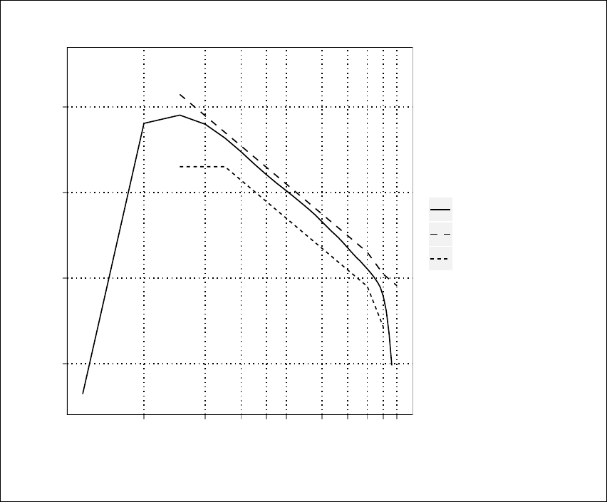
Figure A.1 Receiver frequency response
−20
−10
0
10
200
400
600
800
1000
1500
2000
2500
3000
3500
Frequency − Hz
Response − dB
Actual Response
TIA−603−D maximum
TIA−603−D minimum
Receiver Frequency Response − Deemphasis
TB9400 Specifications Manual Appendix A – Frequency Response Diagrams 49
© Tait Limited July 2017
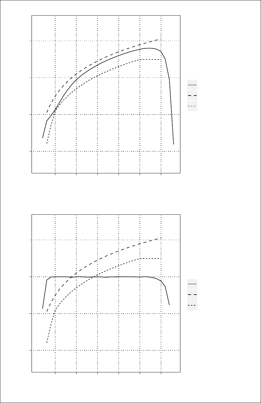
Figure A.2 Transmitter frequency response
−20
−10
0
10
500
1000
1500
2000
2500
3000
Frequency − Hz
Response − dB
Actual Response
TIA−603−D maximum
TIA−603−D minimum
Transmitter Frequency Response − Flat
−20
−10
0
10
500
1000
1500
2000
2500
3000
Frequency − Hz
Response − dB
Actual Response
TIA−603−D maximum
TIA−603−D minimum
Transmitter Frequency Response − Preemphasis