Tait TBCK4B Base Station Transceiver User Manual TB9400 Installation and Operation Manual
Tait Limited Base Station Transceiver TB9400 Installation and Operation Manual
Tait >
Exhibit D Users Manual per 2 1033 c3

DRAFT 4
TB9400 base station
Installation and Operation
Manual
Draft in Progress
MBC-00001-01
Issue 1
September 2011

DRAFT 4
2TB9400 Installation and Operation Manual
© Tait Electronics Limited September 2011
Contact Information
Tait Radio Communications
Corporate Head Office
Tait Electronics Limited
P.O. Box 1645
Christchurch
New Zealand
For the address and telephone number of regional
offices, refer to our website: www.taitradio.com
Copyright and Trademarks
All information contained in this document is the
property of Tait Electronics Limited. All rights reserved.
This document may not, in whole or in part, be copied,
photocopied, reproduced, translated, stored, or reduced
to any electronic medium or machine-readable form,
without prior written permission from Tait Electronics
Limited.
The word TAIT and the TAIT logo are trademarks of
Tait Electronics Limited.
All trade names referenced are the service mark,
trademark or registered trademark of the respective
manufacturers.
Disclaimer
There are no warranties extended or granted by this
document. Tait Electronics Limited accepts no
responsibility for damage arising from use of the
information contained in the document or of the
equipment and software it describes. It is the
responsibility of the user to ensure that use of such
information, equipment and software complies with the
laws, rules and regulations of the applicable
jurisdictions.
Enquiries and Comments
If you have any enquiries regarding this document, or
any comments, suggestions and notifications of errors,
please contact your regional Tait office.
Updates of Manual and Equipment
In the interests of improving the performance, reliability
or servicing of the equipment, Tait Electronics Limited
reserves the right to update the equipment or this
document or both without prior notice.
Intellectual Property Rights
This product may be protected by one or more patents
or designs of Tait Electronics Limited together with
their international equivalents, pending patent or design
applications, and registered trade marks: NZ409837,
NZ409838, NZ508806, NZ508807, NZ509242,
NZ509640, NZ509959, NZ510496, NZ511155,
NZ511421, NZ516280/NZ519742, NZ520650/
NZ537902, NZ521450, NZ522236, NZ524369,
NZ524378, NZ524509, NZ524537, NZ524630,
NZ530819, NZ534475, NZ534692, NZ535471,
NZ537434, NZ546295, NZ547713, NZ569985,
NZ577009, NZ579051, NZ579364, NZ580361,
AU2003281447, AU2004216984, AU2005267973,
AU11677/2008, AU13745/2008,
CN200930004200.4, CN200930009301.0,
CN1031871, CN1070368, EU000915475-0001,
EU000915475-0002, GB2386010, GB23865476,
GB2413249, GB2413445, US5745840, US7411461,
US7649893, US10/523952, US10/546696, US10/
546697, US10/547964, US10/597339, US11/572700,
US29/306491, US61/218015, US61/236663, US61/
238769, US61/251372.
This product may also be made under license under one
or more of the following U.S. Patents: 4,590,473
4,636,791 4,716,407 4,972,460 5,146,497 5,148,482
5,164,986 5,185,795 5,185,796 5,271,017 5,377,229
5,502,767.
The IMBE™ voice coding Technology embodied in
this product is protected by intellectual property rights
including patent rights, copyrights and trade secrets of
Digital Voice Systems, Inc. This voice coding
Technology is licensed solely for use within this
Communications Equipment. The user of this
Technology is explicitly prohibited from attempting to
decompile, reverse engineer, or disassemble the Object
Code, or in any other way convert the Object Code
into a human-readable form. Protected by U.S. Patents
5,870,405 5,826,222 5,754,974 5,701,390 5,715,365
5,649,050 5,630,011 5,581,656 5,517,511 5,491,772
5,247,579 5,226,084 and 5,195,166.
Environmental Responsibilities
Tait Electronics Limited is an
environmentally responsible company
which supports waste minimization,
material recovery and restrictions in the
use of hazardous materials.
The European Union’s Waste Electrical and Electronic
Equipment (WEEE) Directive requires that this product
be disposed of separately from the general waste stream
when its service life is over. For more information
about how to dispose of your unwanted Tait product,
visit the Tait Electronics WEEE website at
www.taitradio.com/weee. Please be environmentally
responsible and dispose through the original supplier, or
contact Tait Electronics Limited.
Tait Electronics Limited also complies with the
Restriction of the Use of Certain Hazardous Substances
in Electrical and Electronic Equipment (RoHS)
Directive in the European Union.
In China, we comply with the Measures for
Administration of the Pollution Control of Electronic
Information Products. We will comply with
environmental requirements in other markets as they are
introduced.

DRAFT 4
TB9400 Installation and Operation Manual 3
© Tait Electronics Limited September 2011
Contents
Preface . . . . . . . . . . . . . . . . . . . . . . . . . . . . . . . . . . . . . . . . . . . . . . . . . . . . . 6
Scope of Manual . . . . . . . . . . . . . . . . . . . . . . . . . . . . . . . . . . . . . . . . . . . . . . . . . . . . 6
Document Conventions . . . . . . . . . . . . . . . . . . . . . . . . . . . . . . . . . . . . . . . . . . . . . . . 6
Associated Documentation . . . . . . . . . . . . . . . . . . . . . . . . . . . . . . . . . . . . . . . . . . . . . 7
Publication Record . . . . . . . . . . . . . . . . . . . . . . . . . . . . . . . . . . . . . . . . . . . . . . . . . . 7
1 Description. . . . . . . . . . . . . . . . . . . . . . . . . . . . . . . . . . . . . . . . . . . . . . . . 9
1.1 Features . . . . . . . . . . . . . . . . . . . . . . . . . . . . . . . . . . . . . . . . . . . . . . . . . . . . . . 10
1.2 Modules. . . . . . . . . . . . . . . . . . . . . . . . . . . . . . . . . . . . . . . . . . . . . . . . . . . . . . 11
1.3 Mechanical Assembly . . . . . . . . . . . . . . . . . . . . . . . . . . . . . . . . . . . . . . . . . . . . 14
1.4 Frequency Bands and Sub-bands . . . . . . . . . . . . . . . . . . . . . . . . . . . . . . . . . . . . 17
1.5 Applications . . . . . . . . . . . . . . . . . . . . . . . . . . . . . . . . . . . . . . . . . . . . . . . . . . . 17
1.6 Licenses . . . . . . . . . . . . . . . . . . . . . . . . . . . . . . . . . . . . . . . . . . . . . . . . . . . . . . 18
1.7 Theory of Operation. . . . . . . . . . . . . . . . . . . . . . . . . . . . . . . . . . . . . . . . . . . . . 19
1.7.1 Signal Paths. . . . . . . . . . . . . . . . . . . . . . . . . . . . . . . . . . . . . . . . . . . . 21
1.7.2 Online and Offline Modes . . . . . . . . . . . . . . . . . . . . . . . . . . . . . . . . . 21
1.7.3 Intermodule Communications . . . . . . . . . . . . . . . . . . . . . . . . . . . . . . 22
1.7.4 Power Management and Distribution . . . . . . . . . . . . . . . . . . . . . . . . . 23
1.7.5 PMU Operation on DC Input . . . . . . . . . . . . . . . . . . . . . . . . . . . . . . 25
1.7.6 Front Panel Fans . . . . . . . . . . . . . . . . . . . . . . . . . . . . . . . . . . . . . . . . 28
2 General Safety and Regulatory Information. . . . . . . . . . . . . . . . . . . . . . . . . 29
2.1 Personal Safety . . . . . . . . . . . . . . . . . . . . . . . . . . . . . . . . . . . . . . . . . . . . . . . . . 29
2.1.1 Unpacking and Moving the Equipment . . . . . . . . . . . . . . . . . . . . . . . 29
2.1.2 Lethal Voltages . . . . . . . . . . . . . . . . . . . . . . . . . . . . . . . . . . . . . . . . . 29
2.1.3 AC Power Connection . . . . . . . . . . . . . . . . . . . . . . . . . . . . . . . . . . . 30
2.1.4 Explosive Environments . . . . . . . . . . . . . . . . . . . . . . . . . . . . . . . . . . 30
2.1.5 Proximity to RF Transmissions . . . . . . . . . . . . . . . . . . . . . . . . . . . . . 30
2.1.6 High Temperatures . . . . . . . . . . . . . . . . . . . . . . . . . . . . . . . . . . . . . . 30
2.1.7 LED Safety (EN60825-1) . . . . . . . . . . . . . . . . . . . . . . . . . . . . . . . . . 30
2.2 Equipment Safety . . . . . . . . . . . . . . . . . . . . . . . . . . . . . . . . . . . . . . . . . . . . . . . 31
2.2.1 Installation and Servicing Personnel . . . . . . . . . . . . . . . . . . . . . . . . . . 31
2.2.2 Preventing Damage to the PA . . . . . . . . . . . . . . . . . . . . . . . . . . . . . . 31
2.2.3 ESD Precautions . . . . . . . . . . . . . . . . . . . . . . . . . . . . . . . . . . . . . . . . 31
2.2.4 Anti-tampering Devices . . . . . . . . . . . . . . . . . . . . . . . . . . . . . . . . . . . 32
2.3 Environmental Conditions . . . . . . . . . . . . . . . . . . . . . . . . . . . . . . . . . . . . . . . . 32
2.3.1 Operating Temperature Range . . . . . . . . . . . . . . . . . . . . . . . . . . . . . 32
2.3.2 Humidity . . . . . . . . . . . . . . . . . . . . . . . . . . . . . . . . . . . . . . . . . . . . . 32
2.3.3 Dust and Dirt . . . . . . . . . . . . . . . . . . . . . . . . . . . . . . . . . . . . . . . . . . 32
2.4 Regulatory Information . . . . . . . . . . . . . . . . . . . . . . . . . . . . . . . . . . . . . . . . . . 33
2.4.1 Distress Frequencies. . . . . . . . . . . . . . . . . . . . . . . . . . . . . . . . . . . . . . 33
2.4.2 FCC Compliance . . . . . . . . . . . . . . . . . . . . . . . . . . . . . . . . . . . . . . . 33
2.4.3 Unauthorized Modifications. . . . . . . . . . . . . . . . . . . . . . . . . . . . . . . . 33
DRAFT 4
4TB9400 Installation and Operation Manual
© Tait Electronics Limited September 2011
2.4.4 Health, Safety and Electromagnetic Compatibility in Europe. . . . . . . . 34
3 Operation . . . . . . . . . . . . . . . . . . . . . . . . . . . . . . . . . . . . . . . . . . . . . . . . 35
3.1 Front Panel . . . . . . . . . . . . . . . . . . . . . . . . . . . . . . . . . . . . . . . . . . . . . . . . . . . 36
3.2 Module Indicator LEDs and Switches . . . . . . . . . . . . . . . . . . . . . . . . . . . . . . . . 40
3.2.1 Reciter . . . . . . . . . . . . . . . . . . . . . . . . . . . . . . . . . . . . . . . . . . . . . . . 40
3.2.2 PA . . . . . . . . . . . . . . . . . . . . . . . . . . . . . . . . . . . . . . . . . . . . . . . . . . 42
3.2.3 PMU . . . . . . . . . . . . . . . . . . . . . . . . . . . . . . . . . . . . . . . . . . . . . . . . 43
4 Working with Base Stations from Your PC . . . . . . . . . . . . . . . . . . . . . . . . . 45
4.1 PC Recommendations . . . . . . . . . . . . . . . . . . . . . . . . . . . . . . . . . . . . . . . . . . . 46
4.2 Connecting Your PC to the Base Station. . . . . . . . . . . . . . . . . . . . . . . . . . . . . . 46
4.2.1 Logging In . . . . . . . . . . . . . . . . . . . . . . . . . . . . . . . . . . . . . . . . . . . . 47
4.2.2 Setting the IP Address . . . . . . . . . . . . . . . . . . . . . . . . . . . . . . . . . . . . 48
4.2.3 Responding to Security Warnings . . . . . . . . . . . . . . . . . . . . . . . . . . . 49
4.2.4 Connecting a Networked PC to a Base Station. . . . . . . . . . . . . . . . . . 50
4.2.5 Troubleshooting Connection Problems . . . . . . . . . . . . . . . . . . . . . . . 51
4.2.6 Finding a Lost or Forgotten IP Address . . . . . . . . . . . . . . . . . . . . . . . 52
4.3 Working with the Web Interface . . . . . . . . . . . . . . . . . . . . . . . . . . . . . . . . . . . 53
4.3.1 Monitoring Operation. . . . . . . . . . . . . . . . . . . . . . . . . . . . . . . . . . . . 54
4.3.2 Viewing Configuration Settings . . . . . . . . . . . . . . . . . . . . . . . . . . . . . 55
4.3.3 Viewing the Base Station and Network Identity . . . . . . . . . . . . . . . . . 57
4.4 Basic Tasks. . . . . . . . . . . . . . . . . . . . . . . . . . . . . . . . . . . . . . . . . . . . . . . . . . . . 58
4.4.1 User Settings. . . . . . . . . . . . . . . . . . . . . . . . . . . . . . . . . . . . . . . . . . . 58
4.4.2 Taking the Base Station Offline . . . . . . . . . . . . . . . . . . . . . . . . . . . . . 58
4.4.3 Troubleshooting Alarms . . . . . . . . . . . . . . . . . . . . . . . . . . . . . . . . . . 58
4.4.4 Working with Configuration Files . . . . . . . . . . . . . . . . . . . . . . . . . . . 59
4.4.5 Configuring Single Base Stations . . . . . . . . . . . . . . . . . . . . . . . . . . . . 59
4.4.6 Configuring Base Stations in a Channel Group . . . . . . . . . . . . . . . . . . 60
4.4.7 Setting Up Custom Alarms . . . . . . . . . . . . . . . . . . . . . . . . . . . . . . . . 60
4.4.8 Disabling the Front Panel Keypad . . . . . . . . . . . . . . . . . . . . . . . . . . . 60
4.4.9 Preparing to Download Firmware . . . . . . . . . . . . . . . . . . . . . . . . . . . 61
5 Installation . . . . . . . . . . . . . . . . . . . . . . . . . . . . . . . . . . . . . . . . . . . . . . . 63
5.1 Before You Begin . . . . . . . . . . . . . . . . . . . . . . . . . . . . . . . . . . . . . . . . . . . . . . 63
5.1.1 Equipment Security. . . . . . . . . . . . . . . . . . . . . . . . . . . . . . . . . . . . . . 63
5.1.2 Grounding and Lightning Protection . . . . . . . . . . . . . . . . . . . . . . . . . 63
5.1.3 Equipment Ventilation . . . . . . . . . . . . . . . . . . . . . . . . . . . . . . . . . . . 64
5.1.4 Ambient Temperature Sensor . . . . . . . . . . . . . . . . . . . . . . . . . . . . . . 64
5.1.5 Cabinet and Rack Ventilation . . . . . . . . . . . . . . . . . . . . . . . . . . . . . . 65
5.2 Unpacking and Moving the Subrack . . . . . . . . . . . . . . . . . . . . . . . . . . . . . . . . . 67
5.3 Identifying the Equipment . . . . . . . . . . . . . . . . . . . . . . . . . . . . . . . . . . . . . . . . 69
5.4 Initial Setting Up . . . . . . . . . . . . . . . . . . . . . . . . . . . . . . . . . . . . . . . . . . . . . . . 71
5.4.1 Confirming Operation . . . . . . . . . . . . . . . . . . . . . . . . . . . . . . . . . . . 71
5.4.2 Customizing the Configuration . . . . . . . . . . . . . . . . . . . . . . . . . . . . . 73
5.4.3 Changing the Root Password . . . . . . . . . . . . . . . . . . . . . . . . . . . . . . 74
5.4.4 Tuning the Reciter . . . . . . . . . . . . . . . . . . . . . . . . . . . . . . . . . . . . . . 74
DRAFT 4
TB9400 Installation and Operation Manual 5
© Tait Electronics Limited September 2011
5.5 Installing the Base Station on Site . . . . . . . . . . . . . . . . . . . . . . . . . . . . . . . . . . . 75
5.5.1 Base Stations for Trunked Systems . . . . . . . . . . . . . . . . . . . . . . . . . . . 75
5.5.2 Equipment Required. . . . . . . . . . . . . . . . . . . . . . . . . . . . . . . . . . . . . 75
5.5.3 Mounting the Subrack . . . . . . . . . . . . . . . . . . . . . . . . . . . . . . . . . . . . 76
5.6 Connecting Up the Base Station . . . . . . . . . . . . . . . . . . . . . . . . . . . . . . . . . . . . 80
5.6.1 Connection Overview. . . . . . . . . . . . . . . . . . . . . . . . . . . . . . . . . . . . 80
5.6.2 Connecting AC Power . . . . . . . . . . . . . . . . . . . . . . . . . . . . . . . . . . . 81
5.6.3 Connecting DC Power . . . . . . . . . . . . . . . . . . . . . . . . . . . . . . . . . . . 82
5.6.4 Connecting the Auxiliary DC Power Output . . . . . . . . . . . . . . . . . . . 83
5.6.5 Connecting RF. . . . . . . . . . . . . . . . . . . . . . . . . . . . . . . . . . . . . . . . . 84
5.6.6 Connecting an External Frequency Reference . . . . . . . . . . . . . . . . . . 85
5.6.7 Connecting a 1PPS Source . . . . . . . . . . . . . . . . . . . . . . . . . . . . . . . . 86
5.6.8 Ethernet Connection. . . . . . . . . . . . . . . . . . . . . . . . . . . . . . . . . . . . . 86
5.6.9 Connecting General Purpose Inputs and Outputs . . . . . . . . . . . . . . . . 87
6 Maintenance . . . . . . . . . . . . . . . . . . . . . . . . . . . . . . . . . . . . . . . . . . . . . . 89
7 Troubleshooting . . . . . . . . . . . . . . . . . . . . . . . . . . . . . . . . . . . . . . . . . . . 91
8 Replacing Modules . . . . . . . . . . . . . . . . . . . . . . . . . . . . . . . . . . . . . . . . . 93
8.1 Saving the Base Station’s Configuration . . . . . . . . . . . . . . . . . . . . . . . . . . . . . . . 94
8.2 Preliminary Disassembly . . . . . . . . . . . . . . . . . . . . . . . . . . . . . . . . . . . . . . . . . . 95
8.3 Replacing a Reciter . . . . . . . . . . . . . . . . . . . . . . . . . . . . . . . . . . . . . . . . . . . . . 97
8.4 Replacing a Power Amplifier . . . . . . . . . . . . . . . . . . . . . . . . . . . . . . . . . . . . . . 99
8.5 Replacing a Power Management Unit . . . . . . . . . . . . . . . . . . . . . . . . . . . . . . . 101
8.6 Replacing the Front Panel Fans . . . . . . . . . . . . . . . . . . . . . . . . . . . . . . . . . . . . 102
8.7 Replacing the Module Guide Rails . . . . . . . . . . . . . . . . . . . . . . . . . . . . . . . . . 105
8.8 Replacing the Subrack Interconnect Board . . . . . . . . . . . . . . . . . . . . . . . . . . . 106
8.9 Final Reassembly . . . . . . . . . . . . . . . . . . . . . . . . . . . . . . . . . . . . . . . . . . . . . . 107
Appendix A – Interface Pin Allocations . . . . . . . . . . . . . . . . . . . . . . . . . . . . . .109
System Interface Connector . . . . . . . . . . . . . . . . . . . . . . . . . . . . . . . . . . . . . . . . . . 109
Ethernet Connector . . . . . . . . . . . . . . . . . . . . . . . . . . . . . . . . . . . . . . . . . . . . . . . . 109
PMU Auxiliary DC Output . . . . . . . . . . . . . . . . . . . . . . . . . . . . . . . . . . . . . . . . . . 109
Appendix B – Inter-Module Connections . . . . . . . . . . . . . . . . . . . . . . . . . . . . .111
Dual 50W Base Station. . . . . . . . . . . . . . . . . . . . . . . . . . . . . . . . . . . . . . . . . . . . . . 111
Single 50W Base Station. . . . . . . . . . . . . . . . . . . . . . . . . . . . . . . . . . . . . . . . . . . . . 112
100W Base Station . . . . . . . . . . . . . . . . . . . . . . . . . . . . . . . . . . . . . . . . . . . . . . . . . 113
TaitNet P25 Glossary . . . . . . . . . . . . . . . . . . . . . . . . . . . . . . . . . . . . . . . . . . .115
Tait Software License Agreement . . . . . . . . . . . . . . . . . . . . . . . . . . . . . . . . . .129
DRAFT 4
6Preface TB9400 Installation and Operation Manual
© Tait Electronics Limited September 2011
Preface
Scope of Manual
This manual provides information on installing and operating the TB9400
base station. It is intended for use by experienced technicians familiar with
installing and operating base station equipment. It also includes
configuration, maintenance and troubleshooting information.
Document Conventions
The TB9400 base station has a web interface with an accordion menu on
the left side of the screen. “Configure > Base Station > Channels” means
click Configure in the top-level menu, then in the expanded Configure
menu click the + icon beside Base Station to expand its menu tree, and
finally click Channels in this menu tree to display its page.
Within this manual, four types of alerts are given to the reader: Warning,
Caution, Important and Note. The following paragraphs illustrate each type
of alert and its associated symbol.
Warning!! This alert is used when there is a potential risk
of death or serious injury.
Caution This alert is used when there is a risk of minor or
moderate injury to people.
Important This alert is used to warn about the risk of equipment dam-
age or malfunction.
Note This alert is used to highlight information that is required to
ensure procedures are performed correctly.
?These alert icons &
definitions will change.

DRAFT 4
TB9400 Installation and Operation Manual Preface 7
© Tait Electronics Limited September 2011
Associated Documentation
The current set of TB9400 product documentation is provided in PDF
format on the product DVD. Updates are made available on the Tait support
website. Printed copies of the documentation are available on request.
■TB9400 Specifications Manual (MBC-00002-xx).
■TaitNet P25 System Manual (MBA-00032-xx).
■T801-4 GPS Frequency Reference Installation and Operation Manual
(MBA-00033-xx).
Technical notes are published from time to time to describe applications for
Tait products, to provide technical details not included in manuals, and to
offer solutions for any problems that arise. The product DVD includes
technical notes that were available at the time of release. Look for new or
updated technical notes on the Tait support website.
Publication Record
Issue Publication Date Description
1 First release
DRAFT 4
8Preface TB9400 Installation and Operation Manual
© Tait Electronics Limited September 2011

DRAFT 4
TB9400 Installation and Operation Manual Description 9
© Tait Electronics Limited September 2011
1 Description
The Tait TB9400 base station is a robust state-of-the-art digital fixed station
that combines Tait’s proven strengths in reliability, high performance and
modular design with software-based configurability and operation, digital
signal processing and voice-over-IP technology.
The base station is designed for operation in a Project 25 trunked or trunked
simulcast radio network. The ability of the base station to link stations using
standard Internet Protocol communications, and to add features through
software options ensures that P25 systems designed with the TB9400 are
scalable in both size and functionality.
The base station combines industry-leading digital voice quality with
rugged design specifications and intuitive user interfaces. These products
have been designed to meet the demanding needs of the public safety and
public service sectors.
Its Ethernet interface provides built-in network connectivity, allowing the
TB9400 to join with other TB9400 base stations to form a channel group.
This network supports voice over IP and remote management of all base
stations via a web browser.
DRAFT 4
10 Description TB9400 Installation and Operation Manual
© Tait Electronics Limited September 2011
1.1 Features
The following are some of the features of the base station:
■Fully compliant with the Project 25 Common Air Interface. Can
therefore interoperate with any similarly compliant radios.
■Integrated built-in voting facility. No external voter is needed.
■Can be completely managed remotely from a PC running a web
browser: configuration, alarm monitoring, fault diagnosis, feature and
firmware upgrades.
■An integrated wiring solution is provided for the system control bus and
DC power connections to each module in the subrack.
■Reciters can be replaced without affecting the operation of other reciters
in the same subrack.
■Rugged construction with generous heatsinks and fan-forced cooling for
continuous operation from – 30° C to + 60° C (– 22° F to + 140° F).
DRAFT 4
TB9400 Installation and Operation Manual Description 11
© Tait Electronics Limited September 2011
1.2 Modules
The base station consists of a subrack with up to two transmit/receive
channels.
The single PMU (power management unit) supplies and manages power to
the whole subrack (refer to “Theory of Operation” on page 19). One reciter
and one PA (power amplifier) are needed for each transmit/receive channel.
There is also a front panel with user controls and fans. The modules are
interconnected at the front of the subrack. External connections to the
modules are located at the rear.
Modules come in different variants depending, for example, on the RF band
or the supply voltage.
Each module is inserted into the 4 U subrack from the front and is secured
at the front with a metal clamp. Both clamp and module are easily removed
for rapid module replacement. The modules are secured laterally with plastic
guides that clip into the top and bottom of the subrack. These guides can be
easily repositioned to change the configuration of a subrack. The heavier
modules are also secured laterally by metal tabs at the rear of the subrack.
The following provides a brief description of the available modules.
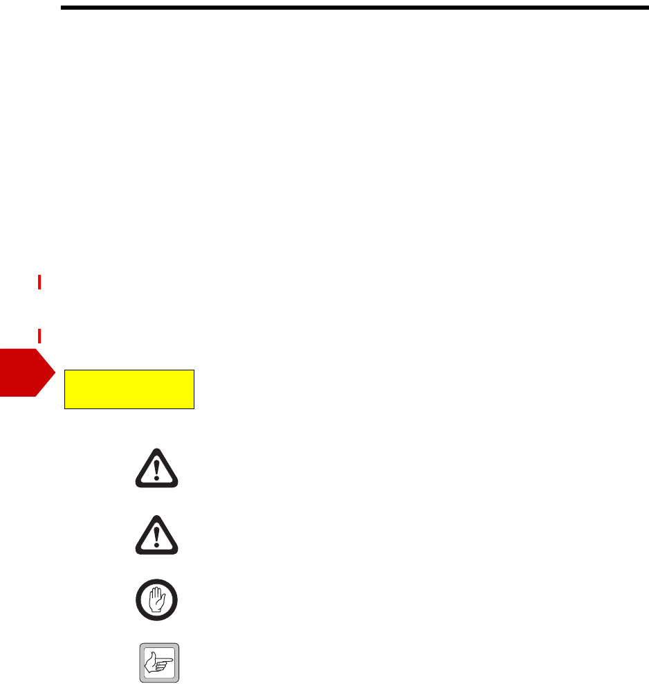
Reciter The reciter module comprises the
receiver, exciter and digital control
circuitry. The reciter provides the
Ethernet interface and system inputs
and outputs.
DRAFT 4
12 Description TB9400 Installation and Operation Manual
© Tait Electronics Limited September 2011
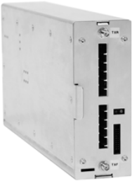
Power Amplifier The PA amplifies the RF output from the reciter and is available in 50 W
and 100 W models.
The 50 W model mounts vertically in the subrack, while the 100 W model
mounts horizontally as it has a wider heatsink. The 100 W PA is also fitted
with an airflow duct.
Both models are designed to operate on the 28 VDC output provided by the
PMU.
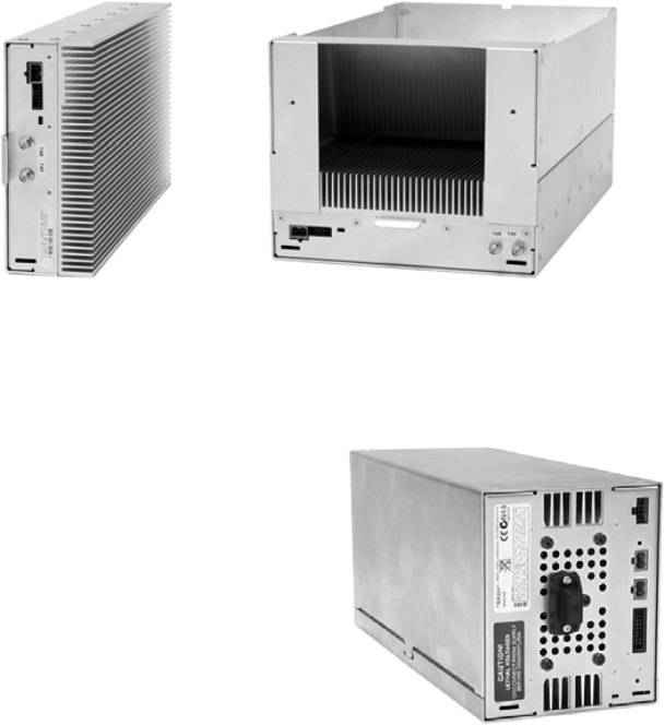
Power
Management Unit The PMU provides the 28 VDC
power supply for the modules in the
subrack. The input voltage can be AC,
DC or both AC and DC, depending
on the model. The PMU also has an
auxiliary DC output of 13.65 VDC,
27.3 VDC, or 54.6 VDC, depending
on the model.
50 W PA 100 W PA
AC and DC PMU shown
DRAFT 4
TB9400 Installation and Operation Manual Description 13
© Tait Electronics Limited September 2011
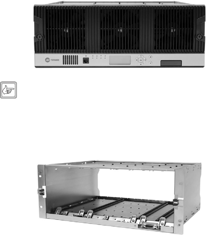
Front Panel The front panel is mounted onto the subrack with two quick-release
fasteners. It incorporates the indicator LEDs, four-line LCD display, user
controls and cooling fans.
The indicator LEDS allow some monitoring of the operational status of the
base station. The user controls and display allow the technician to configure
the IP address of each module. Refer to “Front Panel” on page 36 for more
information.
Note The microphone input and speaker are not used in this release of
the TB9400.
Subrack The 4 U subrack is made of passivated steel and is designed to fit into a
standard 19 inch rack or cabinet. The subrack is fitted with an interconnect
board that connects the system control bus and power to the modules and
front panel. The position of a module in the subrack is defined by the socket
on the subrack interconnect board to which the module is connected by the
system control bus.
DRAFT 4
14 Description TB9400 Installation and Operation Manual
© Tait Electronics Limited September 2011
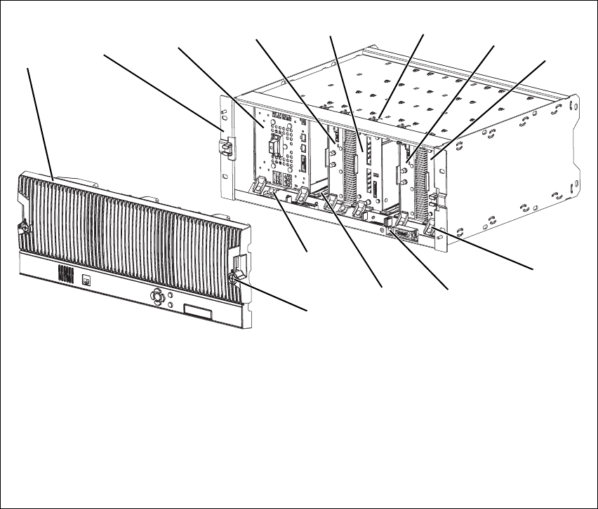
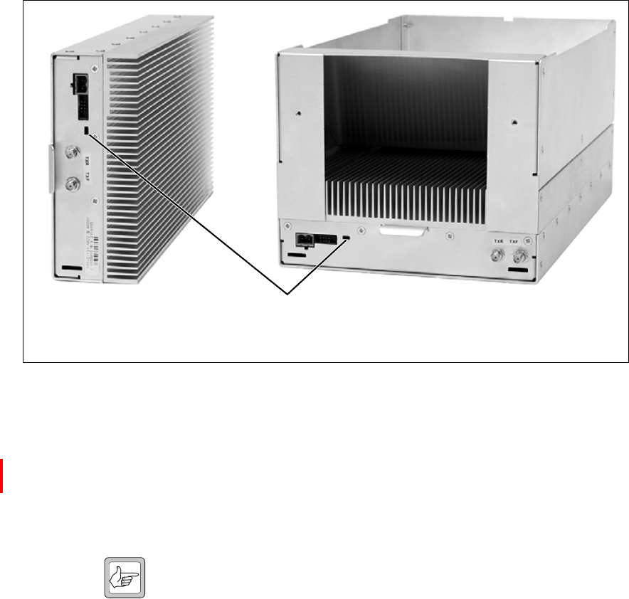
1.3 Mechanical Assembly
This section illustrates the main mechanical components of the base station.
Figure 1.1 below shows the configuration for a typical dual 50 W base
station. The PMU occupies the slot at the left end of the subrack, with the
reciter and PA pairs to the right of it. Each PA is mounted vertically with its
heatsink facing its associated reciter. The PMU and each reciter/PA pair
have their own cooling fans.
The front panel can be easily removed from the subrack by undoing two
quick-release fasteners. Refer to “Replacing Modules” on page 93 for more
details.
.
Figure 1.1 Mechanical assembly - dual 50 W base station with front panel
bfront panel ireciter 1
csubrack jmodule retaining clamp
dPMU 1) subrack interconnect board
ePA 2 1! plastic guide rail
freciter 2 1@ subrack interconnect board retaining clamp
gcable retaining clip 1# front panel fastener
hPA 1
bcdefghi
j
1)
1!
1@
1#
DRAFT 4
TB9400 Installation and Operation Manual Description 15
© Tait Electronics Limited September 2011
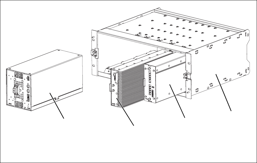
Figure 1.2 below shows the configuration for a typical single 50 W base
station. The PMU occupies its usual slot at the left end of the subrack, with
the reciter and PA pair at the right of the subrack. The PA is mounted
vertically with its heatsink facing the reciter. The PMU and the reciter/PA
pair have their own cooling fans.
Figure 1.2 Mechanical assembly - single 50 W base station
bPMU dreciter
c50 W PA esubrack
bc
de
DRAFT 4
16 Description TB9400 Installation and Operation Manual
© Tait Electronics Limited September 2011
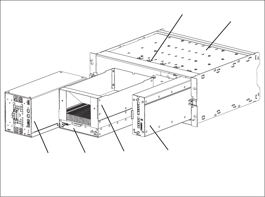
Figure 1.3 below shows the configuration for a typical 100 W base station.
The PMU occupies its usual slot at the left end of the subrack, with the PA
directly beside it. The reciter occupies the slot at the right of the subrack.
Unlike the 50 W PAs, the 100 W PA is mounted horizontally with the
heatsink facing upwards. It is also fitted with an airflow duct to channel the
airflow from the cooling fan through the heatsink fins.
Figure 1.3 Mechanical assembly - single 100 W base station
bPMU ereciter
cPA fsubrack
dairflow duct gcable retaining clip
bcde
f
g

DRAFT 4
TB9400 Installation and Operation Manual Description 17
© Tait Electronics Limited September 2011
1.4 Frequency Bands and Sub-bands
The first release of the base station operates only on K band. Later releases
will support operation on other frequency bands.
1.5 Applications
The TB9400 is designed for operation in a TaitNet P25 trunked radio
network. It can operate as a single base station or as part of a channel group
or simulcast channel group, and as a traffic channel or control channel.
In a trunked simulcast network, the transmitters in the channel group are
synchronized and transmit simultaneously on the same frequency. Each
transmitter needs a highly accurate 1 PPS pulse and an external frequency
reference, so that it can time transmissions with the required accuracy. We
also recommend using an NTP server at each site, as this will ensure a
common timestamp in logs across all units in the system.
For more information, refer to the TaitNet P25 System Manual.
Frequency
Identification Frequency Band and Sub-band
K band K4 = 762 MHz to 870 MHza
a. The actual frequency coverage in this band is:
Transmit: 762 MHz to 776 MHz, and 850 MHz to 870 MHz
Receive: 792 MHz to 824 MHz

DRAFT 4
18 Description TB9400 Installation and Operation Manual
© Tait Electronics Limited September 2011
1.6 Licenses
Some operational functions of the base station are controlled by licenses.
These functions will not work unless you purchase the appropriate feature
license and enable the feature set controlled by that license. The feature sets
currently available are listed below.
P25 Common Air
Interface Allows the base station to go into Online mode. Base stations are always
provided with this license.
P25 Trunking
Operation Allows a base station to participate in a trunking system. Without this
feature, the base station cannot provide a control or a status connection to a
trunking site controller and it cannot function as a control or traffic channel.
Networking with
Centralized Voter Allows the base station to act as a central voter within its channel group. This
feature also allows voice networking. Only base stations that will centrally
vote (normally the central voter and its backup) need this feature. The other
members of the channel group only need the networking with distributed
voter feature. A standard trunked base station (standalone without fill-in
repeaters or other channel group members) can function as a master or a
failsoft repeater without this license.
Simulcast
Transmitter This feature is required in base stations that have transmitters and belong to
a simulcast network.
Simulcast
Modulation Allows the base station to transmit using the LSM modulation scheme. This
scheme is designed to minimize performance degradation in simulcast
channels caused by delay spread.
Failsoft for P25
Trunking Allows trunked channels that become isolated from a site controller to
perform simple conventional operation and to interface to a digital dispatch
system. If a trunked channel consists of several base stations in a channel
group, only the central voter (normally the master) needs this license. It is
then able to become the failsoft repeater for that channel group.
Phase 2 Operation
(not yet available) This feature will allow the base station to operate in trunking mode using
two-slot TDMA as defined by the P25 Phase 2 standard.
DRAFT 4
TB9400 Installation and Operation Manual Description 19
© Tait Electronics Limited September 2011
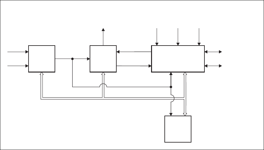
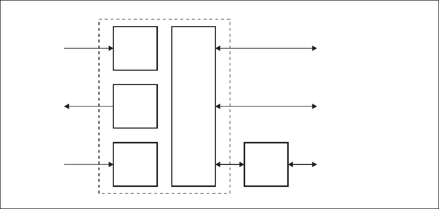
1.7 Theory of Operation
The reciter receives RF signals from its RF input and sends RF from its RF
output to the PA, along with a PA key signal. The PA sends an RF feedback
signal to the reciter for linearization and power control purposes. The reciter
also receives signals from, and sends signals to, the system interface, the
Ethernet interface, and the front panel (see Figure 1.4).
A system control bus interconnects the modules and carries alarm and
control signaling between the reciter and the other modules.
The Ethernet interface carries voice over IP and also allows maintainer
access via a web browser.
Figure 1.4 Base station high-level diagram
Reciter
PMU PA
RF To
Antenna
RF From
Antenna 1PPS*
External
Reference
Frequency*
AC Input
DC Input
28VDC
System Control Bus
RF + PA Key
RF Feedback
System Input
and Output
Ethernet Interface
to Network
Front
Panel
*optional for non-simulcast systems
DRAFT 4
20 Description TB9400 Installation and Operation Manual
© Tait Electronics Limited September 2011
The reciter carries out signal processing and has overall control of the base
station. It has four boards, as shown in Figure 1.5.
The receiver board contains all the receiver circuitry, while the exciter
circuitry is located on the transmit forward board.
The reciter control board converts information between analog and digital
and controls the maintainer’s access via the front panel. It performs the air
interface signal processing for digital P25 mode, gives the base station an
identity as a network element, and provides the physical connections for the
Ethernet and system interfaces.
Figure 1.5 Reciter boards
RF Input
RF Input
(feedback
from PA)
RF Output
Receiver
Board
Transmit
Forward
Board
Transmit
Reverse
Board
Front
Panel
Reciter
Control
Board
Maintainer Access
System Input
and Output
Ethernet Interface
to Network
DRAFT 4
TB9400 Installation and Operation Manual Description 21
© Tait Electronics Limited September 2011
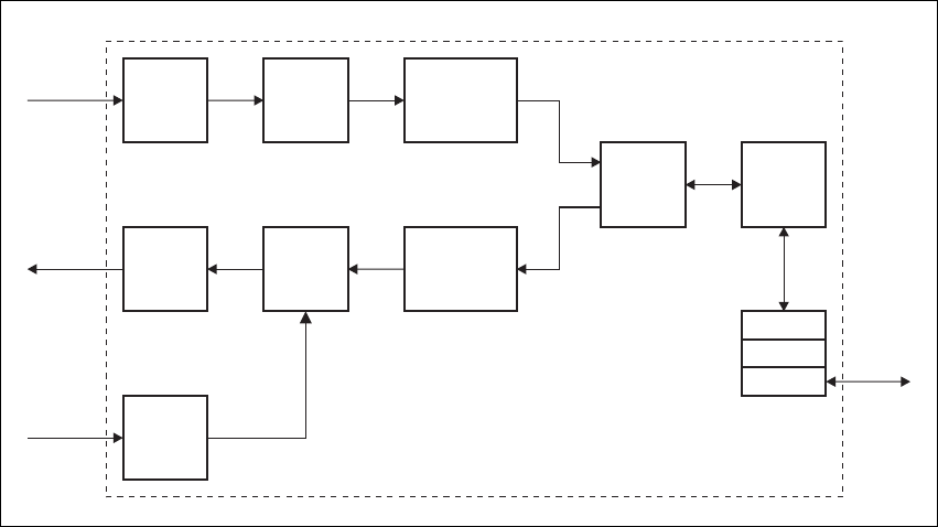
1.7.1 Signal Paths
Figure 1.6 gives an overview of signal paths within the reciter.
Digital P25 signals from the receive RF interface pass through the digital
receiver and P25 modem to the control software in the RISC processor. The
control software passes the signal through the Ethernet interface to the site
controller, or to the central voter in a simulcast system.
Input to the Ethernet interface can be from the site controller, or from the
central voter in a simulcast system. These inputs are processed by the RISC
and passed through the P25 modem to the transmitter. If the base station is
itself a central voter, this input can also be a received signal, which is voted
on and sent back through the Ethernet interface to the site controller.
1.7.2 Online and Offline Modes
The base station normally operates in Online mode, but you can put it into
Offline mode via its web interface.
Online Mode In Online mode, the base station performs its normal functions.
Offline Mode When you program the base station or run invasive diagnostic tests, the base
station must be in Offline mode. This takes the base station out of service.
However, the front panel is still operational and can be used in the normal
way.
Figure 1.6 Reciter signal paths
Modulator
Demodulator
P25
Modem
Cartesian
Loop
Control
ADC
ADC
DDC
DAC
RTP
UDP
IP
Transmit
RF Interface
Transmit
RF Interface
(feedback
from PA)
Receive
RF Interface
Ethernet
Interface
Protocol
Stack
Reciter Control Board
DRAFT 4
22 Description TB9400 Installation and Operation Manual
© Tait Electronics Limited September 2011
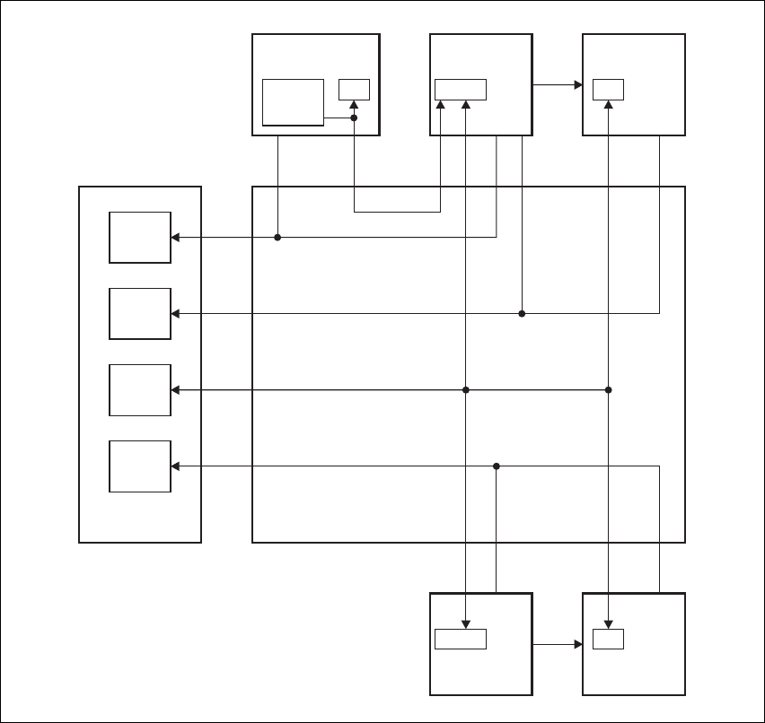
1.7.3 Intermodule Communications
A system control bus and a subrack interconnect board link the modules in
the subrack and carry alarm and control signaling between the reciter and
the other modules, as shown in Figure 1.7.
Figure 1.7 Intermodule communication paths
FanFan
Fan
I C
2
RS-485RS-485
RS-485
RS-485I C
2Fan
PA Fan
PMU Fan
Fan
PA 1
μP
Subrack Interconnect Board
PA 2
μP
Reciter 1
μP
Front Panel
PMU
Fan
Reciter 1/
PA 1 Fan
Reciter 2/
PA 2 Fan
Reciter 2
μP
User
Controls
PMU
μP
I C Current
Source
2

DRAFT 4
TB9400 Installation and Operation Manual Description 23
© Tait Electronics Limited September 2011
1.7.4 Power Management and Distribution
The PMU manages the supply of power to ensure uninterrupted operation
of the base station. A range of parameters is monitored and these can trigger
alarms that are sent to the reciter. Alarms can be monitored via the web
interface, and are also recorded in the reciter’s internal log file.
AC to DC
Changeover When the PMU has an AC and a DC module, the base station can be
powered by either the AC (mains) or the DC (battery) supply. The base
station will default to the AC supply if both supplies are provided. If the AC
supply becomes unavailable, a seamless changeover from the AC to DC
supply takes place, providing that the battery voltage is above the configured
minimum. You can use a web browser to check whether the base station is
running on battery or mains power.
DC Operation When the base station is running off the DC supply and the battery voltage
falls below the configured minimum, the base station will enter battery
protection mode to protect the battery and base station equipment. The
standby power supply card maintains the power to the PMU microprocessor,
while the rest of the PMU is shut down. When the battery voltage rises to
the configured startup setting, power is resumed to the DC supply. Refer to
“PMU Operation on DC Input” on page 25 for more detailed information.
Auxiliary Power
Control The output from the auxiliary power supply board can be used to power
other site equipment. The maximum output is 40 W.
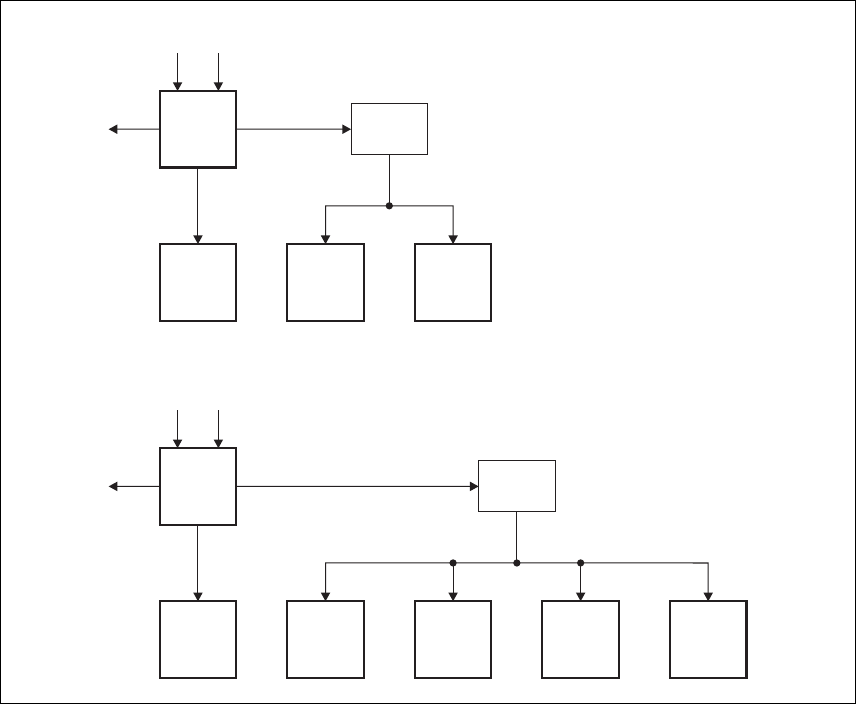
Distribution Figure 1.8 shows how power is distributed to modules in the subrack. The
28 VDC output from the PMU is fed directly to the 100 W PA and 50 W
PA1, and to the other modules via the subrack interconnect board. Power
to the reciters and front panel is current-limited by self-resetting fuses on the
subrack board.
The AC converter has a series switch which breaks the phase input to the
converter. The DC input, however, has much higher current ratings. Its
switch does not disconnect power from the DC converter itself, but disables
the converter by switching off its control circuitry.
The outputs from both the AC and DC high power converters are added
together and fed to the modules via the high-current outputs. The auxiliary
output is also tapped off this summed output.
DRAFT 4
24 Description TB9400 Installation and Operation Manual
© Tait Electronics Limited September 2011
Figure 1.8 Subrack power distribution for single and dual base stations
DC AC
28V
Aux. DC 28V
PMU
PA Reciter
Subrack
Board
Front
Panel
DC AC
28V
Aux. DC 28V
PMU
PA 1 PA 2 Reciter 1
Subrack
Board
Reciter 2 Front
Panel
Single
Dual

DRAFT 4
TB9400 Installation and Operation Manual Description 25
© Tait Electronics Limited September 2011
1.7.5 PMU Operation on DC Input
The operation of the PMU on DC input is controlled by three sets of
parameters:
■user-programmable alarms
■user-programmable startup and shutdown limits
■battery protection limits
The voltage range for each of these parameters is provided in Table 1.1 on
page 26. Figure 1.9 on page 27 illustrates how these parameters interact, and
how they control the operation of the PMU over a range of DC input
voltages.
Alarms User-programmable alarms can be set for low or high battery voltage
(Configure > Alarms > Thresholds). The alarms will be triggered when the
set voltage levels are reached. These limits are subject to the tolerances of the
battery protection circuitry, as stated in “Battery Protection (Fail-safe)
Limits” in Table 1.1.
Startup and
Shutdown Limits The user-programmable startup and shutdown limits allow for adjustable
startup and shutdown voltages (Configure > Base Station > Miscellaneous).
These limits can be adjusted for different numbers of battery cells, or for the
particular requirements of the base station operation. Once the limits are
reached, the PMU will shut down. These limits are subject to the tolerances
of the battery protection circuitry, as stated in “Battery Protection (Fail-safe)
Limits” in Table 1.1.
Important It is possible to set the startup voltage of the base station
below the nominal voltage of the battery. Continuing to use
a battery for extended periods when it is below its nominal
voltage will severely shorten its service life. For more infor-
mation on battery management, we recommend that you
consult the battery manufacturer.
Battery Protection
Limits The battery protection limits are set in hardware at the factory, and cannot
be adjusted by the user. These limits will not be reached under normal
operation conditions, but are provided as “fail-safe” measures to protect the
battery from deep discharge. They also remove the need for low-voltage
disconnect modules.

DRAFT 4
26 Description TB9400 Installation and Operation Manual
© Tait Electronics Limited September 2011
Table 1.1 PMU DC voltage limitsa
Parameter
Voltage Range
12 V PMU 24 V PMU 48 V PMU
User-programmable Alarmsb
Low Battery Voltage
High Battery Voltage
10 V to 14 V
14 V to 17.5 V
20 V to 28 V
28 V to 35 V
40 V to 56 V
56 V to 70 V
User-programmable Limitsbc
Startup Voltage (after shutdown)
Shutdown Voltage
10.9 V to 15 V ± 0.3 V
10 V to 13.5 V ± 0.3 V
21.8 V to 30 V ± 0.3 V
20 V to 27 V ± 0.3 V
43.6 V to 60 V ± 0.3 V
40 V to 54 V ± 0.3 V
Battery Protection (Fail-safe) Limits
Startup Voltage
Undervoltage Shutdown
Overvoltage Shutdown
Overvoltage Shutdown Reset
10.8 V +0.2 V
9.5 V +0.3 V
18.1 V +0.3 V
17.1 V +0.3 V
21.6 V +0.5 V
19 V +0.5 V
36.2 V +0.5 V
34.2 V +0.5 V
43.2 V +1 V
38 V +1 V
72.4 V +1 V
68.4 V +1 V
a. The information in this table is extracted from the Specifications Manual. Refer to the latest issue of this manual
for the most up-to-date and complete PMU specifications.
b. Using the base station’s web interface.
c. These limits are subject to the tolerances of the battery protection circuitry.
DRAFT 4
TB9400 Installation and Operation Manual Description 27
© Tait Electronics Limited September 2011
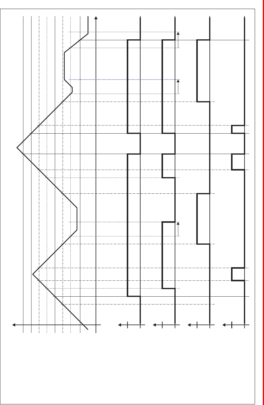
Figure 1.9 PMU alarm thresholds and voltage limits when operating on DC
Time
0V
DC Input Voltage
Overvoltage Shutdown (HW)
Undervoltage Shutdown (HW)
Overvoltage Shutdown Reset (HW)
High Battery Voltage Alarm (SW Alarm)
Low Battery Voltage Alarm (SW Alarm)
Startup Voltage (SW)
Shutdown Voltage (SW)
Startup Voltage (HW)
Run
Run
Stop
Stop
Active
Active
Off
Off
Software Control &
Hardware Combined
Hardware Behaviour
Software Alarm
(Low Battery Voltage)
Software Alarm
(High Battery Voltage)
30s delay 30s delay 30s delay

DRAFT 4
28 Description TB9400 Installation and Operation Manual
© Tait Electronics Limited September 2011
1.7.6 Front Panel Fans
The front panel is equipped with three fans. One fan is for the PMU and
the other two are for the reciter/PA pairs in a 50 W base station, or for the
PA and reciter in a 100 W base station. Front panel fans do not operate
continuously but are switched on and off as needed by the reciter firmware.
Each reciter controls the fan it shares with its PA, and reciter 1 also controls
the PMU fan. Under certain conditions the PMU and each PA can override
the reciter and assume control of its own fan.
Front panel fans are 3-wire fans (power, ground, and rotation detect). The
reciter can monitor whether the fans are rotating and generate an alarm if
the fan fails.
The fans turn on for a few seconds when the base station is powered up, and
also after the front panel is refitted to a base station which is powered up.
Configuring Fan
Control The operation of the PA fan is configurable via the web interface; you can
specify the threshold temperature at which the fan will be turned on, and
set the fan to operate only when the PA is transmitting.
The PMU fan has fixed on/off thresholds and a defined set of duty cycles
based on the PMU temperature, as described in the following table:
PMU Temperature Fan Duty Cycle
<149 °F (65 °C) Increases as the load on the PMU
increases
149-167 °F (65-75 °C) On for two minutes, off for one minute
>167 °F (75 °C) Always on
DRAFT 4
TB9400 Installation and Operation Manual General Safety and Regulatory Information 29
© Tait Electronics Limited September 2011
2 General Safety and Regulatory
Information
This chapter provides general information on safety precautions for
operating the base station.
2.1 Personal Safety
2.1.1 Unpacking and Moving the Equipment
To prevent personal injury and equipment damage, we recommend that two
people unpack and move the equipment.
Caution A subrack complete with modules can weigh up to
55 lb (25 kg), or up to 62 lb (28 kg) complete with
packaging. We recommend that you have another
person help you unpack and move the equipment.
The TBAA03-16 carrying handles will make it easier
to move the equipment once it has been unpacked.
If necessary, remove the modules from the subrack
before moving it (refer to “Replacing Modules” on
page 93). In all cases follow safe lifting practices.
2.1.2 Lethal Voltages
Warning!! The PMU contains voltages that may be lethal.
Refer to the ratings label on the rear of the
module.
The equipment must be installed so that the rear of the PMU is located in
a service access area which is accessible only by qualified personnel. The
PMU must be connected to the mains supply source by qualified personnel
in accordance with local and national regulations.
Disconnect the mains IEC connector and wait for five minutes for
the internal voltages to self-discharge before dismantling. The AC
power on/off switch does not isolate the PMU from the mains. It
breaks only the phase circuit, not the neutral.
The PMU should be serviced only by qualified technicians. There are no
user-replaceable parts inside. If the PMU is damaged and does not function

DRAFT 4
30 General Safety and Regulatory Information TB9400 Installation and Operation Manual
© Tait Electronics Limited September 2011
properly, stop the module safely and contact your regional Tait office
immediately.
All servicing should be carried out only when the PMU is powered through
a mains isolating transformer of sufficient rating.
2.1.3 AC Power Connection
2.1.4 Explosive Environments
Warning!! Do not operate the equipment near electrical
blasting caps or in an explosive atmosphere.
Operating the equipment in these environments
is a definite safety hazard.
2.1.5 Proximity to RF Transmissions
Do not operate the transmitter when someone is standing within 3 ft (90 cm)
of the antenna. Do not operate the transmitter unless you have checked that
all RF connectors are secure.
2.1.6 High Temperatures
Take care when handling a PMU or PA which has been operating recently.
Under extreme operating conditions (+ 140° F [+60° C] ambient air
temperature) or high duty cycles, the external surfaces of the PMU and PA
can reach temperatures of up to + 176° F (+ 80° C).
2.1.7 LED Safety (EN 60825-1)
This equipment contains Class 1 LED Products.
English (en) The PMU must be connected to a grounded mains
socket-outlet.
Norsk (no) Apparatet må tilkoples jordet stikkontakt.
Suomi (fi) Laite on liitettävä suojamaadoitus-koskettimilla
varustettuun pistorasiaan.
Svenska (sv) Apparaten skall anslutas till jordat uttag.
DRAFT 4
TB9400 Installation and Operation Manual General Safety and Regulatory Information 31
© Tait Electronics Limited September 2011
2.2 Equipment Safety
2.2.1 Installation and Servicing Personnel
The equipment should be installed and serviced only by qualified personnel.
2.2.2 Preventing Damage to the PA
The base station has been designed to operate safely under a wide range of
antenna loading conditions. Transmitting into a low VSWR will maximize
the power delivered to the antenna.
Important Do not remove the load from the PA while it is
transmitting.
Load transients (switching or removing the load) or atmospheric
disturbances (for example rain static and electrical storms) can damage the
PA output stage. See “Connecting RF” on page 84 for recommendations.
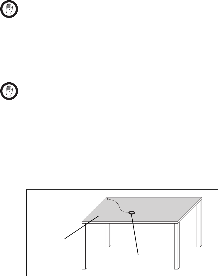
2.2.3 ESD Precautions
Important This equipment contains devices which are susceptible to
damage from static charges. You must handle these devices
carefully and according to the procedures described in the
manufacturers’ data books.
We recommend you purchase an antistatic bench kit from a reputable
manufacturer and install and test it according to the manufacturer’s
instructions. Figure 2.1 shows a typical antistatic bench set-up.
You can obtain further information on antistatic precautions and the dangers
of electrostatic discharge (ESD) from standards such as ANSI/ESD
S20.20-1999 or BS EN 100015-4 1994.
Figure 2.1 Typical antistatic bench set-up
common point ground
(building ground or
mains ground)
conductive wrist strap
dissipative rubber
bench mat
DRAFT 4
32 General Safety and Regulatory Information TB9400 Installation and Operation Manual
© Tait Electronics Limited September 2011
2.2.4 Anti-tampering Devices
All network elements should be physically secured, where possible. This
includes the use of locked cabinets and the use of seals on connectors.
All network and audio connectors should be sealed with the stick-on type
of seal. The purpose of the seals is to detect unauthorized tampering. The
seal should reveal if any of the connectors have been unplugged or if any
unauthorized equipment has been plugged in.
The seals must be difficult to remove without breaking, and must bridge
between the cable and equipment side (plug and socket) of the connection.
Seals must cover any unused network or audio sockets. This includes the
Ethernet connector on the rear panel, any spare switch ports, and the
console port on the router and switch.
The seals must be difficult to reproduce. A sticker initialed or signed by the
technician should satisfy this.
Seals must be replaced if they need to be disturbed during maintenance.
2.3 Environmental Conditions
2.3.1 Operating Temperature Range
The operating temperature range of the equipment is – 22°F to + 140°F
(– 30°C to + 60°C) ambient temperature. Ambient temperature is defined as
the temperature of the air at the intake to the cooling fans.
2.3.2 Humidity
The humidity should not exceed 95% relative humidity through the
specified operating temperature range.
2.3.3 Dust and Dirt
For uncontrolled environments, the level of airborne particulates must not
exceed 100 µg/m3.
DRAFT 4
TB9400 Installation and Operation Manual General Safety and Regulatory Information 33
© Tait Electronics Limited September 2011
2.4 Regulatory Information
2.4.1 Distress Frequencies
The 406 to 406.1 MHz frequency range is reserved worldwide for use by
Distress Beacons. Do not program transmitters to operate in this frequency
range.
2.4.2 FCC Compliance
This equipment complies with:
■CFR Title 47 Part 15 Class B (except PMU):
Radiated and conducted emissions, and electromagnetic susceptibility
specifications of the Federal Communications Commission (FCC) rules
for the United States.
Operation is subject to the following two conditions:
a. This device may not cause harmful interference, and
b. This device must accept any interference received, including
interference that may cause undesired operation.
■CFR Title 47 Part 15 Class A (PMU only):
Radiated and conducted emissions, and electromagnetic susceptibility
specifications of the Federal Communications Commission (FCC) rules
for the United States.
Operation is subject to the following two conditions:
a. This device may not cause harmful interference, and
b. This device must accept any interference received, including
interference that may cause undesired operation.
2.4.3 Unauthorized Modifications
Any modifications you make to this equipment which are not authorized by
Tait Electronics Limited may invalidate your compliance authority’s approval
to operate the equipment.

DRAFT 4
34 General Safety and Regulatory Information TB9400 Installation and Operation Manual
© Tait Electronics Limited September 2011
2.4.4 Health, Safety and Electromagnetic Compatibility in Europe
In the European Community, radio and telecommunications equipment is
regulated by Directive 1999/5/EC, also known as Radio and
Telecommunications Terminal Equipment (R&TTE) directive. The
requirements of this directive include protection of health and safety of users,
as well as electromagnetic compatibility.
Intended Purpose of
Product This product is a radio transceiver. It is intended for radio communications
in the Private Mobile Radio (PMR) or Public Access Mobile Radio
(PAMR) services, to be used in all member states of the European Union
(EU) and states within the European Economic Area (EEA). This product
can be programmed to transmit on frequencies that are not harmonized
throughout the EU/EEA, and will require a licence to operate in each
member state.
Declaration of
Conformity You can download the formal Declaration of Conformity from
http://eudocs.taitradio.com/. You can also obtain a signed and dated paper
copy of the Declaration of Conformity from Tait Electronics Limited.

DRAFT 4
TB9400 Installation and Operation Manual Operation 35
© Tait Electronics Limited September 2011
3 Operation
This section describes the user controls and indicator LEDs on the front
panel and on the base station modules.
DRAFT 4
36 Operation TB9400 Installation and Operation Manual
© Tait Electronics Limited September 2011
3.1 Front Panel
The user controls and indicator LEDs on the front panel are shown in
Figure 3.1. They allow some manual control over the base station and
monitoring of its operational status.
Note If there is more that one reciter in a subrack, inputs from all recit-
ers are summed to drive the front panel LEDs.
Speaker and
Microphone
Connector
The speaker and microphone connector are not used in this release of the
base station.
Power LED The green power LED is lit when power is supplied to the subrack.
Alarm LED The red alarm LED will flash at a rate of 2 to 5 Hz when an alarm has been
generated by any of the base station modules. It will continue to flash until
the alarm is canceled or the fault is fixed. Note that only those alarms which
are enabled using the web interface will cause this LED to flash.
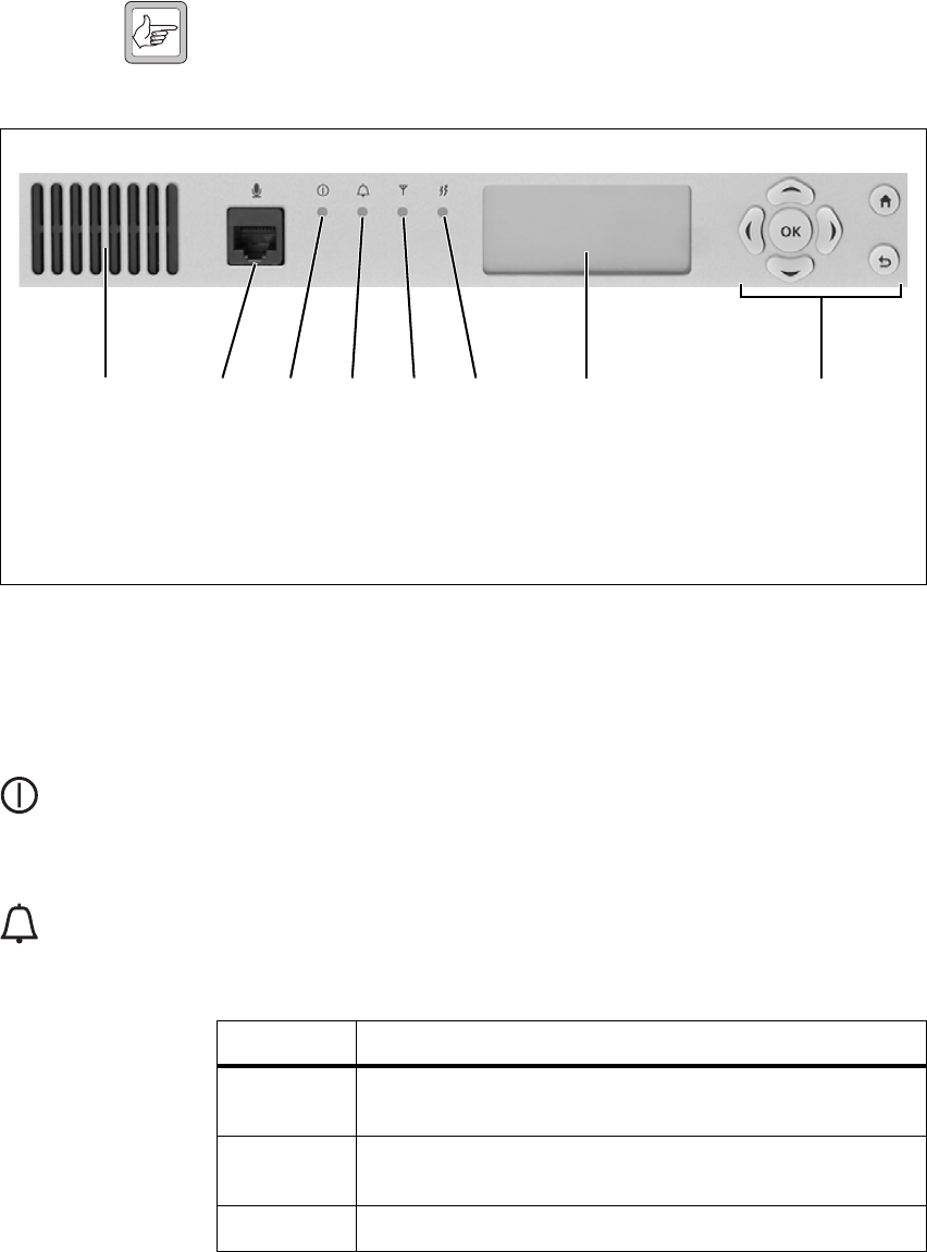
Figure 3.1 Operating controls on the control panel
bspeaker freceive LED
cmicrophone connector gtransmit LED
dpower LED hkeypad
ealarm LED idisplay
bcdefgi h
b c
d
e
LED Description
On (steady) The base station is in Offline mode (regardless of the presence of
any fault).
Flashing The base station is in Online mode, and one or more faults are
present.
Off The base station is in Online mode, and no faults are present.
DRAFT 4
TB9400 Installation and Operation Manual Operation 37
© Tait Electronics Limited September 2011
Receive LED The amber receive LED indicates whether the base station is receiving a
valid RF signal.
Transmit LED The amber transmit LED is lit while the transmitter is transmitting.
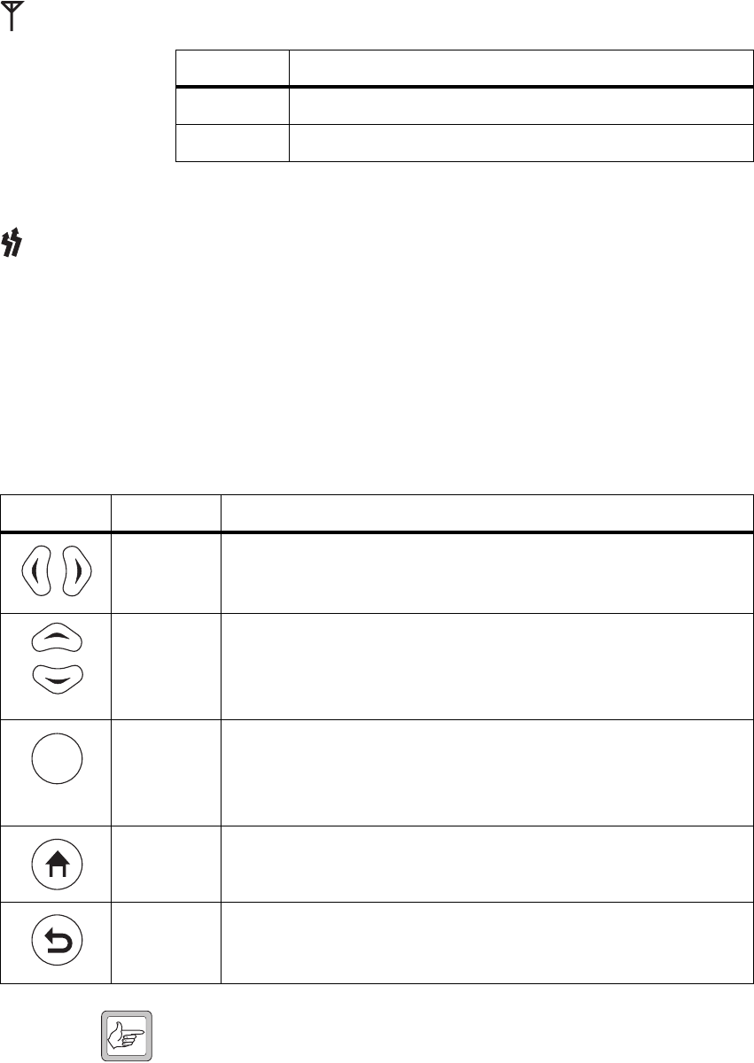
Keypad The keypad is used to navigate the base station’s menus, enter text, and to
adjust the contrast of the display. The complete list of menu items is provided
in “Menu Map” on page 39.
If required, the keypad can be disabled in the web interface to prevent access
to the base station via the front panel menus (see “Disabling the Front Panel
Keypad” on page 60).
Note Unlike a computer keyboard, the keys do not auto-repeat. Each
action requires a separate key-press.
f
LED Description
On (steady) The base station is receiving a valid RF signal.
Off The base station is not receiving a valid RF signal.
g
h
Key Name Function
left and right
arrow keys
■Move the cursor to the left or right when entering text. Moving the cursor
beyond the end of a line will return it to the other end of the same line.
■Decrease or increase the contrast in the Display Contrast screen.
scroll keys ■Scroll up and down through a list of menu items.
■Scroll up and down through the list of available characters when entering
text.
■Increase or decrease the contrast in the Display Contrast screen.
OK ■Selects the highlighted menu item.
■Confirms any adjustments made and exits to the previous menu.
■When setting the IP address, moves the cursor down one line. When all
the IP addresses are confirmed, exits to the previous menu.
home ■Returns to the idle screen from any other menu.
return ■Returns to the previous menu.
■Moves the cursor up one line in the IP address screen. When the top line is
reached, pressing again returns to the previous menu.
OK

DRAFT 4
38 Operation TB9400 Installation and Operation Manual
© Tait Electronics Limited September 2011
Display The display is used in conjunction with the keypad to access the base
station’s menus. It allows the technician to configure the IP address of each
reciter (refer to “Setting the IP Address” on page 48), and to set the contrast
of the display (see below).
After the base station is powered up, the display shows “Please wait . . .” while
the base station is starting up, followed by the idle screen when the start-up
process is complete. If the front panel loses communication with reciter 1,
the display also shows “Please wait . . .”, and the alarm LED flashes. If the base
station is activating new firmware, the display is blank and the power LED
flashes. The idle screen shows four lines of user-defined text, which can be
entered via the web interface (Identity > Identity > Base Station Identity).
From the idle screen press an arrow key, a scroll key or OK to go to the base
station menu. The display returns to the idle screen from any other screen
30 seconds after the last key press. Press any key to turn on the backlight.
The backlight turns off 30 seconds after the last key press.
Note If the keypad has been disabled, pressing an arrow key, a scroll key
or OK will cause the display to show “Keypad Disabled”.
Set the display contrast as follows:
1. From the base station menu select Modules > Front Panel > Contrast.
2. To increase the contrast, press the right arrow or scroll up key. To
decrease the contrast, press the left arrow or scroll down key.
3. When the contrast is set to the required level, press OK to save the
changes and exit the menu.
i
DRAFT 4
TB9400 Installation and Operation Manual Operation 39
© Tait Electronics Limited September 2011
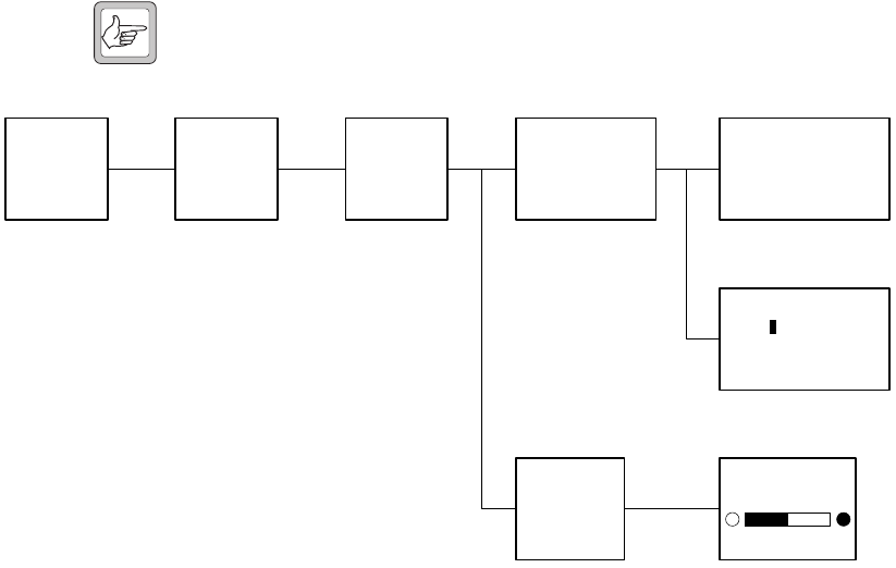
Menu Map The menu map below shows the menu items available in this release of the
base station.
Note The menu map shown is for a single base station. The menu items
available in your base station will depend on the modules present
in the subrack.
Modules
Reciter 1
Reciter 2
Front Panel
Base Station
Modules
Reciter 1
View Reciter 1 Address
Edit Reciter 1 Address
Front Panel
Contrast
Idle Screen
Contrast
View Reciter 1 Address
IP: 172.025.198.043
MASK: 255.255.000.000
GW: 172.025.002.251
Edit Reciter 1 Address
IP: 172.025.198.043
MASK: 255.255.000.000
GW: 172.025.002.251
1
DRAFT 4
40 Operation TB9400 Installation and Operation Manual
© Tait Electronics Limited September 2011
3.2 Module Indicator LEDs and Switches
Additional status information is displayed by LEDs in individual modules.
The PMU also has switches that let you turn the AC and DC modules off.
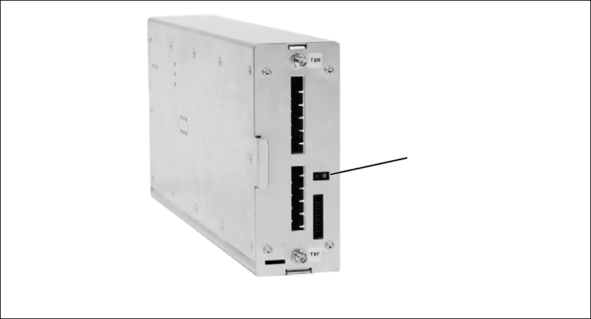
3.2.1 Reciter
Front View The indicator LEDs on the front of the reciter are visible through a slot in
its front panel.
These LEDs provide the following information about the state of the reciter:
■steady green - the reciter is powered up
■flashing red - one or more alarms have been generated; you can use the
web interface to find out more details about the alarms.
Figure 3.2 Indicator LEDs on the front of the reciter
bindicator LEDs
b
DRAFT 4
TB9400 Installation and Operation Manual Operation 41
© Tait Electronics Limited September 2011
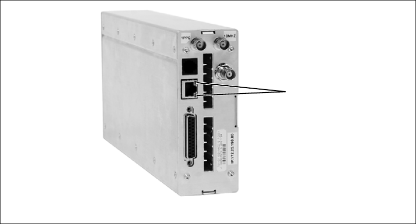
Rear View The indicator LEDs on the rear of the reciter are on the Ethernet connector.
These LEDs provide the following information about the state of the reciter:
■steady amber - the Ethernet interface is connected
■flashing green - data is being transmitted across the Ethernet interface.
Figure 3.3 Indicator LEDs on the rear of the reciter
bindicator LEDs
b
DRAFT 4
42 Operation TB9400 Installation and Operation Manual
© Tait Electronics Limited September 2011
3.2.2 PA
The indicator LEDs on the PA are visible through a slot in its front panel.
Indicator LEDs These LEDs provide the following information about the state of the PA:
■steady green - the PA is powered up
■flashing green - the PA has no application firmware loaded or activated;
you can use the web interface to download or activate the firmware; also
see “Preparing to Download Firmware” on page 61
■flashing red - one or more alarms have been generated; you can use the
web interface to find out more details about the alarms.
Note The alarm LED will flash whenever an alarm is generated,
whether or not this alarm has been disabled via the web interface.
Figure 3.4 Indicator LEDs on the PA
bindicator LEDs
b
50 W PA 100 W PA
DRAFT 4
TB9400 Installation and Operation Manual Operation 43
© Tait Electronics Limited September 2011
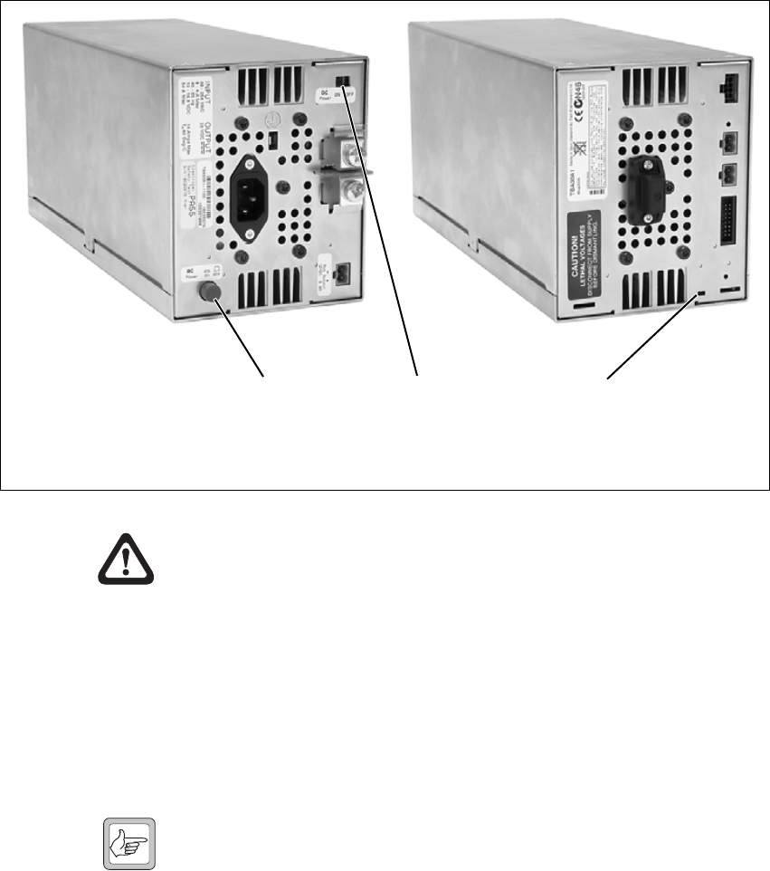
3.2.3 PMU
The only controls on the PMU are the on/off switches on the rear panel for
the AC and DC modules, and the indicator LEDs visible through a slot in
its front panel.
Warning!! The AC and DC module on/off switches do not
totally isolate the internal circuitry of the PMU
from the AC or DC power supplies. You must
disconnect the AC and DC supplies from the
PMU before dismantling or carrying out any
maintenance. Refer to the service manual for
the correct servicing procedures.
AC Module On/Off
Switch This switch turns the AC input to the PMU on and off. Note that this
switch breaks only the phase circuit, not the neutral.
Note On switches fitted to PMUs up to November 2008, the red button
is “in” when on, and “out” when off. On switches fitted from
November 2008 onwards, the red button remains “out” whether
on or off.
Figure 3.5 Operating controls on the PMU
bAC module on/off switch dindicator LEDs
cDC module on/off switch
bc
rear view
d
front view

DRAFT 4
44 Operation TB9400 Installation and Operation Manual
© Tait Electronics Limited September 2011
DC Module On/Off
Switch This switch turns the DC output from the PMU on and off. Note that this
switch does not disconnect power from the DC converter itself. It disables
the converter by switching off its control circuitry. Even when the DC
converter is off, the DC input is still connected to its power circuitry.
The switch is recessed to prevent the DC module being accidentally
switched off, thus disabling the battery back-up supply.
Indicator LEDs These LEDs provide the following information about the state of the PMU:
■steady green - the PMU is powered up
■flashing green - the PMU has no application firmware loaded or
activated; you can use the web interface to download or activate the
firmware; also see “Preparing to Download Firmware” on page 61
■flashing red - one or more alarms have been generated; you can use the
web interface to find out more details about the alarms.
Note The alarm LED will flash whenever an alarm is generated,
whether or not this alarm has been disabled via the web interface.

DRAFT 4
TB9400 Installation and Operation Manual Working with Base Stations from Your PC 45
© Tait Electronics Limited September 2011
4 Working with Base Stations from Your
PC
The normal web browser on your PC provides a window into the TB9400
base station. Use it to connect to the base station so that you can monitor,
configure, diagnose, and calibrate it (if required).
This section describes the following:
■Connecting to the base station, including initially setting things up.
■Wo r k i n g w i t h base station web pages.
■Carrying out basic tasks.
This section provides an overview of some aspects of the web interface.
Refer to the Help for detailed instructions.
DRAFT 4
46 Working with Base Stations from Your PC TB9400 Installation and Operation Manual
© Tait Electronics Limited September 2011
4.1 PC Recommendations
We recommend the following PC hardware and software for connecting to
a TB9400 base station:
■SVGA Monitor (1024 x 768 minimum).
■Network connection.
■Mozilla Firefox version 3.6 and later, Microsoft Internet Explorer
version 8 and later.
Note We h ave t e s t e d t h e base station with Firefox 3.6 and Internet
Explorer 8. If you encounter problems with your web browser,
change to one of these browsers.
4.2 Connecting Your PC to the Base Station
You connect to a base station using your web browser. Using multiple
browser windows or tabs, you can view more than one base station and more
than one page of any base station at once. Base stations have a web-based
interface that provides the pages you view. Up to five users may be logged
in to a base station at once.
The base station has three different user access levels: Administrator,
Maintainer, and Guest. Passwords can be defined for the Administrator and
Maintainer levels. This is done using the base station’s web interface (Tools >
Tools > User Administration). Refer to the Help for more information on
setting user access levels.
DRAFT 4
TB9400 Installation and Operation Manual Working with Base Stations from Your PC 47
© Tait Electronics Limited September 2011
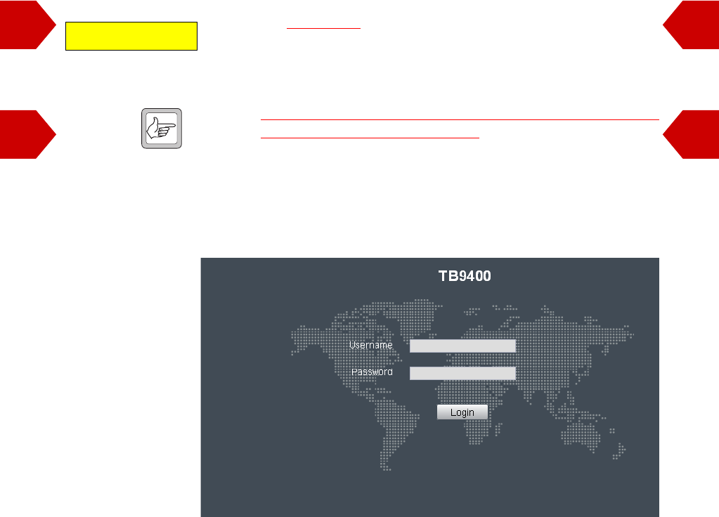
4.2.1 Logging In
1. Enter the base station’s URL into your browser: the default address is
https://192.168.1.2 (note the use of a secure-socket connection). To
find out the base station’s IP address, on the front panel select Mod-
ules > Reciter 1 (or 2) > View Reciter 1 (or 2) Address. To set the
IP address, refer to “Setting the IP Address” on page 48.
Note If access to this menu on the front panel has been disabled, you can
find out the IP address by .....how??
2. A security warning appears when you connect for the first time.
Proceed anyway (refer to “Responding to Security Warnings” on
page 49).
3. The login screen appears.
4. Enter your user name and password. When connecting for the first
time, enter the user name “admin” and password “tbc_admin”.
5. Click Login.
Verify default address.
??
??

DRAFT 4
48 Working with Base Stations from Your PC TB9400 Installation and Operation Manual
© Tait Electronics Limited September 2011
4.2.2 Setting the IP Address
Before the base station is installed on site, you need to provide it with its
proper IP address. Make sure that you do not lose this address. A quick way
to set the base station’s IP address is to use the front panel, as described
below.
Note If access to this menu on the front panel has been disabled, log in
to the base station and set the IP address using the web interface
(Identity > Identity > Network Identity).
1. Use the front panel display to enter the IP address, subnet mask and
gateway specified for this base station by the IP addressing plan for the
network. From the base station menu select Modules > Reciter 1
(or 2) > Edit Reciter 1 (or 2) Address. If the idle screen is showing,
press an arrow key, a scroll key or OK to clear it.
Important In this screen each octet in the address lines has provision
for three characters. If an octet in the address has less than
three characters, enter one or two leading zeroes so that
each position is filled, even though the zeroes are not part
of the address. For example, enter 172.25.506.47 as
172.025.506.047. Leading zeroes are removed when the
address is programmed into the base station.
2. Set each address as described below. Use the left and right arrow keys
to move the cursor across each line in the Addresses screen. Use the
scroll keys to scroll through the available numbers for each position in
a line.
a. Set the IP address and press OK. This moves the cursor to the next
line. To move the cursor back to the previous line, press the return
key.
b. Set the Mask address and press OK.
c. Set the Gateway address and press OK.
d. The display shows “Setting Reciter 1 (or 2) address Please wait...”
while the base station confirms that the addresses are correct.
When this process has finished, the display will show
“SUCCEEDED” or “FAILED” as appropriate. Press OK to return to
the previous menu.
3. If the process failed, try entering the address again. It it still fails, try
the following:
■enter the address through the web interface
■check that the IP address you are trying to enter is not already in
use by another device on the same subnet.
DRAFT 4
TB9400 Installation and Operation Manual Working with Base Stations from Your PC 49
© Tait Electronics Limited September 2011
4.2.3 Responding to Security Warnings
When your browser connects to a TB9400 for the first time, it raises a
security warning. Normally, secure websites have a security certificate issued
by a trusted Certification Authority. This is to foil attempts by rogue
websites to pretend to be something they are not. Obtaining such certificates
is impractical for each installed TB9400, so a self-signed certificate is created
when the reciter’s firmware is installed.
Your browser raises a security warning because the security certificate was
not issued by a trusted Certification Authority. The browser has a way of
letting you override or bypass the security warning. In Internet Explorer,
you install a certificate, in Mozilla Firefox you add an exception, and in
Google Chrome you elect to proceed anyway.
You can be confident that you are not connecting to a rogue website
pretending to be your TB9400, so follow the procedure below to tell the
browser that the security certificate is OK. The browser then stores the
security certificate and will not raise a warning on subsequent connections,
unless the IP address of the TB9400 changes or you use a different URL
such as https://127.0.0.1. For more information, refer to
http://support.microsoft.com/kb/931850 (Internet Explorer) or search for
“security certificate” in your browser’s Help.
Firefox 1. When the message “This Connection is Untrusted” appears, click
I Understand the Risks.
2. Click Add Exception.
3. The Location field includes details specific to your TB9400. Without
changing the default values, click Confirm Security Exception.
Internet Explorer 1. Click Continue to this website (not recommended).
2. Click Certificate Error.
3. Click View certificates. The Certificate dialog box, General tab is
displayed.
4. Click Install Certificate and then follow the Certificate Import
Wizard to install the certificate. Proceed to the end without changing
the default values. When the Security Warning window appears, click
Yes.
DRAFT 4
50 Working with Base Stations from Your PC TB9400 Installation and Operation Manual
© Tait Electronics Limited September 2011
4.2.4 Connecting a Networked PC to a Base Station
You may want to temporarily disconnect a networked PC from its LAN in
order to be able to establish a direct connection with the base station. A
physical connection is needed as well as an alternate (Windows 7, Windows
Vista, Windows XP) or temporary (Windows 2000) IP address and subnet
mask.
Windows 7 or
Windows Vista 1. Remove the local area Ethernet connection and connect an Ethernet
patch cable between the PC and the base station. You can use either
a straight through or crossover Ethernet patch cable with the current
base station firmware.
2. Navigate to Control Panel > Network and Internet > Network and
Sharing Center.
3. Click View status.
4. In the Local Area Connection Status dialog box, click Properties.
5. In the Local Area Connection Properties dialog box, click Internet
Protocol Version 4 (TCP/IPv4), and then click Properties.
6. Click Alternate Configuration.
7. Select the User configured option, and then enter a number that is on
the same subnet as the base station. For example, if the TB9400 has
IP 192.168.1.2, enter 192.168.1.1 for the PC.
8. Enter a suitable subnet mask, for example 255.255.255.0.
The web browser should now be able to connect to any physically
connected base station that is on the same subnet.
9. Once the web browser session is finished, re-connect the local area
network cable to the PC. The PC then uses its normal TCP/IP
properties.
Windows XP
Professional 1. Remove the local area Ethernet connection and connect an Ethernet
patch cable between the PC and the base station. You can use either
a straight through or crossover Ethernet patch cable with the current
base station firmware.
2. Click Start > Settings > Control Panel.
3. Double-click Network Connections.
4. Double-click the Local Area Network icon.
5. Click Properties.
6. Click Internet Protocol (TCP/IP), and then click Properties.
7. Click Alternate Configuration.
DRAFT 4
TB9400 Installation and Operation Manual Working with Base Stations from Your PC 51
© Tait Electronics Limited September 2011
8. Select the User configured option, and then enter a number that is on
the same subnet as the base station. For example, if the TB9400 has
IP 192.168.1.2, enter 192.168.1.1 for the PC.
9. Enter a suitable subnet mask, for example 255.255.255.0.
The web browser should now be able to connect to any physically
connected base station that is on the same subnet.
10. Once the web browser session is finished, re-connect the local area
network cable to the PC. The PC then uses its normal TCP/IP
properties.
Windows 2000 1. Remove the local area Ethernet connection and connect an Ethernet
patch cable between the PC and the base station. You can use either
a straight through or crossover Ethernet patch cable with the current
base station firmware.
2. Select Start > Settings > Network and Dialup Connections.
3. Double-click the Local Area Connection icon.
4. Click Properties.
5. Click Internet Protocol (TCP/IP), and then click Properties.
6. Note the current settings so that you can restore them later.
7. Select Use the following IP address, and then enter a number that
is on the same subnet as the base station. For example, if the base
station has IP 192.168.1.2, enter 192.168.1.1 for the PC.
8. Enter a suitable subnet mask, for example 255.255.255.0.
The web browser should now be able to connect to the base station.
9. When you have finished the web browser session, re-connect the
local area network cable to the PC and then restore the original PC
configuration. When you close the Network connection dialog box,
the restored configuration is applied.
4.2.5 Troubleshooting Connection Problems
If the attempt to connect to a base station failed, consider these possible
causes.
1. Your PC is part of your organization’s LAN and does not belong to
the same subnet as the base station. Give the PC a suitable IP address
and subnet mask as described in “Connecting a Networked PC to a
Base Station” on page 50.
2. You are attempting to connect to the wrong IP address. Check that
the IP address is correct.
DRAFT 4
52 Working with Base Stations from Your PC TB9400 Installation and Operation Manual
© Tait Electronics Limited September 2011
Note You can quickly check the base station’s IP address via the front
panel, as long as access to this menu has not been disabled.
3. The link to the base station is down. Use ping to check.
4. You may have to bypass the proxy in your organization’s LAN to
access the TaitNet P25 Network. Ask your system administrator to
give you access.
4.2.6 Finding a Lost or Forgotten IP Address
Use the following procedure if an IP address has been lost or forgotten.
1. Mount the reciter in a TB9400 subrack and fit the front panel. Power
up the subrack.
2. On the front panel display select Modules > Reciter 1 (or 2) > View
Reciter 1 (or 2) Address.
?
What do you do if access
to this front panel menu
has been blocked via the
web interface?
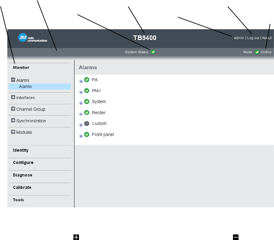
DRAFT 4
TB9400 Installation and Operation Manual Working with Base Stations from Your PC 53
© Tait Electronics Limited September 2011
4.3 Working with the Web Interface
This section provides an overview of the web interface. Refer to the Help
for detailed instructions.
When you connect to a base station, the browser displays a page like the
following.
The accordion menu on the left gives you access to the various pages. Click
a top level item (such as Configure) to open up its menu. Click the + icon
( ) on a menu item to expand the menu tree and the – icon ( ) to collapse
it again. Click an item in an expanded menu tree to display its page.
You can have more than one page open at the same time. Right-click an
item on the menu and select “Open link in new tab” or “Open link in new
window”. You can also wheel-click an item to open it in a new tab.
Press F11 for a full-screen display of the browser which does not show
toolbars and other information. Press F11 again to return to the standard
view.
Accordion
menu
Model and name of
base station
Alarm status. Click
System Status to
go to the Alarms
screen.
Mode (online or
offline). Click
Mode to go to the
screen where you
can change mode.
Click to
disconnect
Status bar Click your user
name to change
your password
and user settings
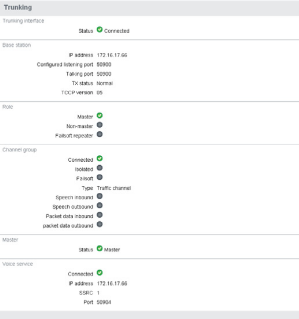
DRAFT 4
54 Working with Base Stations from Your PC TB9400 Installation and Operation Manual
© Tait Electronics Limited September 2011
4.3.1 Monitoring Operation
Using the monitoring pages, you can see how the base station is currently
operating.
For example, you can see the status of its trunking interface (Monitor >
Interfaces > Trunking).
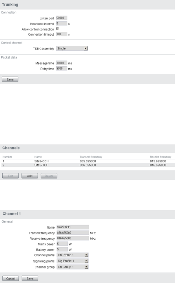
DRAFT 4
TB9400 Installation and Operation Manual Working with Base Stations from Your PC 55
© Tait Electronics Limited September 2011
4.3.2 Viewing Configuration Settings
The base station has many configuration settings that personalize it for its
particular role in the network. Some settings, such as those for the trunking
interface (Configure > Network Interfaces > Trunking), always apply.
Others are channel-based so that they can be dynamically changed. To view
these, you first need to know the channel that the base station is operating
on. Select Identity > Identity > Base Station to see its default channel
number. Then you can view the base station’s channel configuration
settings. Select Configure > Base Station > Channels to view the list of
channels.
Select a channel and click Edit to view details of the channel. Clicking
directly on any text in a line will also open the edit screen.
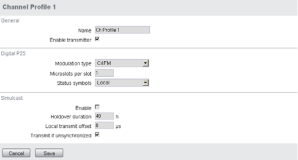
DRAFT 4
56 Working with Base Stations from Your PC TB9400 Installation and Operation Manual
© Tait Electronics Limited September 2011
Channel and signaling settings are grouped together in profiles. The channel
configuration indicates the number of the currently active profile. To view
the channel profile settings, select Configure > RF Interface > Channel
Profiles and then click the relevant profile number.
Proceed in a similar way to view signaling profile and channel group settings.
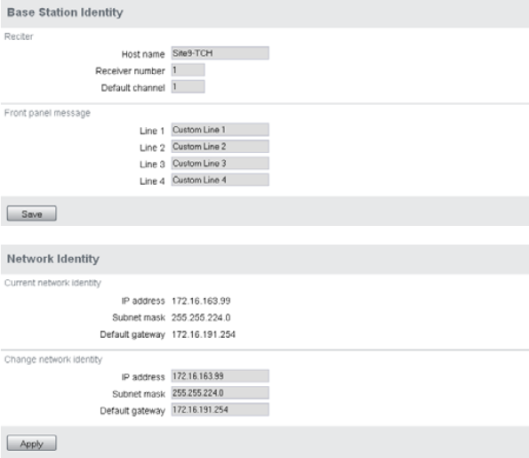
DRAFT 4
TB9400 Installation and Operation Manual Working with Base Stations from Your PC 57
© Tait Electronics Limited September 2011
4.3.3 Viewing the Base Station and Network Identity
Each base station in a network has a unique base station and network
identity.
Select Identity > Identity and then Base Station or Network to view details
such as name, receiver number, default channel and network addresses. Note
that the Host Name field has a maximum of 63 characters, and may use the
characters a – z, 0 – 9, dot and hyphen.
You can also enter here the four lines of information you want to appear on
the front panel display (at start-up and when idle). Each line has a maximum
of 20 characters.
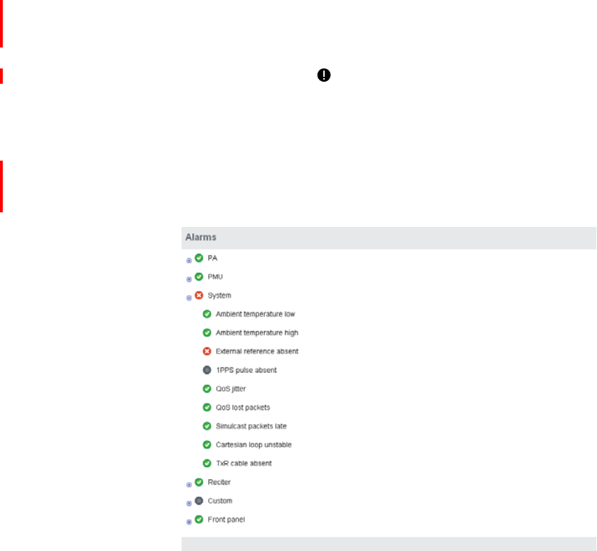
DRAFT 4
58 Working with Base Stations from Your PC TB9400 Installation and Operation Manual
© Tait Electronics Limited September 2011
4.4 Basic Tasks
4.4.1 User Settings
Click on your user name in the top right corner of the page to choose
whether the temperature is displayed in Fahrenheit or Celsius, and to change
your password.
4.4.2 Taking the Base Station Offline
You may need to take the base station offline in order to carry out diagnostic
tests or to take it out of service if a fault develops.
1. Click Mode on the status bar (or Select Tools > Tools > Base Station).
2. Under Control, select Offline. Click Offline to confirm the change.
In the Status area, the Mode display changes first to “Changing”, and
then to “Offline” ( ).
4.4.3 Troubleshooting Alarms
If the Alarm status on the status bar displays red, one or more alarms have
been triggered, and the Alarms menu automatically expands to display the
alarm(s). Click Help and navigate to the description of that alarm.
DRAFT 4
TB9400 Installation and Operation Manual Working with Base Stations from Your PC 59
© Tait Electronics Limited September 2011
4.4.4 Working with Configuration Files
At any time, you can save the current configuration settings as a file
(Tools > Tools > Configurations). This is stored in the base station, but you
can download it and store it on your computer as an off-site backup. The
base station identity and network identity are not saved as part of the
configuration file.
You may want to develop a master configuration and upload it to all base
stations in the network, The master configuration can contain all the
different channel configurations and can be common to all base stations. The
base station identity selects the default channel.
4.4.5 Configuring Single Base Stations
Most base stations in non-simulcast trunked networks are single. They
interface to a site controller but not to other base stations. The following
explains the special considerations when configuring single base stations.
Channel Group
Membership Although single base stations are not actually part of a channel group, their
channel configurations (Configure > Base Station > Channels) must still
select a channel group (Configure > Channel Group > Channel Groups).
Channel Group IP
Address The selected channel group must be configured for single base station
operation. Specify 127.0.0.1 as the channel group IP address. This stops the
base station from attempting to send voice packets to other base stations.
Preamble Although the single base station’s transmitter does not receive voice packets
from other channel group members, it still receives them from other base
stations via trunking controllers. So, while most channel group settings have
no effect, the preamble setting still applies and determines how large the
transmit buffer is.
The default setting of 40 ms is intended for internal jitter only. If the base
station is a traffic channel, you may have to increase the preamble. Voice
arriving at the base station’s trunking interface has travelled from another
base station via the trunking site controller and could have significantly more
jitter.
Marshalling
Duration If the base station is a control channel, the channel group settings should
specify fixed marshalling and allow a duration of 40 ms. This gives the
control channel’s transmitter an appropriate buffer (control channels do not
use the preamble to regulate the transmit buffer). Marshalling duration does
not apply to traffic channels.
Trunking Interface Single base stations need a control connection to their site controller. A
single base station interfaces to the site controller in the same way as the
DRAFT 4
60 Working with Base Stations from Your PC TB9400 Installation and Operation Manual
© Tait Electronics Limited September 2011
master base station in a trunked channel group. Select Configure > Network
Interfaces > Trunking to configure this.
4.4.6 Configuring Base Stations in a Channel Group
You can configure the way the base station behaves in its channel group.
Also, qualified network engineers can change DSCP assignments, so that
routers and switches provide a different quality of service to different types
of IP packets.
In trunked networks, many base stations are single and not actually part of a
channel group. However, they still must be assigned to a channel group
configuration and some of its parameters must be set correctly.
4.4.7 Setting Up Custom Alarms
Each of the base station’s 12 digital inputs can be used to raise a custom alarm
when the input goes high or low. The Custom Alarms form (Configure >
Alarms > Custom Alarms) allows you to assign a name to each custom
alarm, and to configure whether the alarm is triggered when the digital
input goes high or low.
Custom alarms are used to provide an alarm when an external event activates
a digital input. You can rename any of the available alarms to provide a more
meaningful name, such as “Door open”.
4.4.8 Disabling the Front Panel Keypad
You can disable the front panel keypad to prevent access to the base station
via the front panel menus. Select Configure > Base Station > Miscellaneous
and in the Front Panel area clear the Keypad enabled check box.

DRAFT 4
TB9400 Installation and Operation Manual Working with Base Stations from Your PC 61
© Tait Electronics Limited September 2011
4.4.9 Preparing to Download Firmware
New versions of base station firmware are remotely downloaded to base
stations from a package server. A package server is a basic web server
application. The product DVD provides the Mongoose web server.
Note You do not have to install Mongoose to make it work, because
mongoose-3.0.exe is a self-sufficient executable file.
You can set up a single PC to be the central package server for all the base
stations on the network using mongoose or any web server. You can also use
a laptop as a temporary package server.
To set up a PC as a package server, proceed as follows.
1. Insert the product DVD in the computer’s DVD drive.
2. If the DVD does not autorun, navigate to the DVD’s root folder and
double-click mongoose-3.0.exe. An “m” icon appears in the system
tray to indicate that the package server is running.
3. If the PC is to be the central package server, configure each base
station with the package server’s IP address and port.
a. Select Configure > Base Station > Miscellaneous.
b. Under Package server, enter the IP address of the package server.
4. If a laptop is to be a temporary package server, temporarily override
the package server IP address and port in each base station.
a. Select Tools > Tools > Firmware Download.
b. Under Package server, enter the IP address of the laptop.
You can now instruct a base station to list and download firmware from the
package server.
DRAFT 4
62 Working with Base Stations from Your PC TB9400 Installation and Operation Manual
© Tait Electronics Limited September 2011

DRAFT 4
TB9400 Installation and Operation Manual Installation 63
© Tait Electronics Limited September 2011
5 Installation
This chapter provides information on the site requirements for your TB9400
equipment and also describes how to install the base station in a standard
19 inch rack or cabinet.
If this is your first time installing a TB9400 base station, we recommend that
you read the entire chapter before beginning the actual installation.
5.1 Before You Begin
5.1.1 Equipment Security
The security of your base station equipment is a high priority. If the site is
not fully secure, the base station should at least be locked in a secure cabinet
to prevent unauthorized access.
5.1.2 Grounding and Lightning Protection
Electrical Ground The base station modules are grounded by physical contact between the
module case and the subrack. To ensure a good ground connection you must
tighten each module retaining clamp securely (refer to “Final Reassembly”
on page 107 for the correct torque).
A threaded grounding connector is provided on the rear of the subrack for
connection to the site ground point (refer to “Connecting Up the Base
Station” on page 80 for more details).
Lightning Ground It is extremely important for the security of the site and its equipment that
you take adequate precautions against lightning strike. Because it is outside
the scope of this manual to provide comprehensive information on this
subject, we recommend that you conform to your country’s standards
organization or regulatory body.

DRAFT 4
64 Installation TB9400 Installation and Operation Manual
© Tait Electronics Limited September 2011
5.1.3 Equipment Ventilation
Always ensure there is adequate ventilation around the base station.
Warning!! Do not operate it in a sealed cabinet. You must
keep the ambient temperature within the speci-
fied range, and we strongly recommended that
you ensure that the cooling airflow is not
restricted.
Important The cooling fans are mounted on the front panel and will
only operate when the panel is fitted correctly to the front
of the subrack. To ensure adequate airflow through the base
station, do not operate it for more than a few minutes with
the front panel removed (e.g. for servicing purposes).
5.1.4 Ambient Temperature Sensor
The ambient temperature reading for the base station is provided by the
temperature sensor located on the front panel circuit board.

DRAFT 4
TB9400 Installation and Operation Manual Installation 65
© Tait Electronics Limited September 2011
5.1.5 Cabinet and Rack Ventilation
The cooling airflow for the base station enters through the front panel and
exits at the rear of the subrack. For optimum thermal performance, the
heated air that has passed through a base station must not be allowed to re-
enter the air intakes on the front panel. Any space at the front of the cabinet
not occupied by equipment should be covered by a blanking panel. Refer
to Figure 5.1 on page 66.
To allow enough cooling airflow through a cabinet-mounted base station,
we recommend the following:
■an area of at least 23 in2 (150 cm2) of unrestricted ventilation slots or holes
in front of the air intakes for the fans for each subrack; for example, thirty
0.25 x 3.3 in (6 x 85 mm) slots will allow the recommended airflow
■a vent in the top of the cabinet with an area of approximately 23 in2
(150 cm2) per subrack, or a similar area of ventilation per subrack at the
rear of the cabinet behind each subrack
■a 2 U gap at the top of the cabinet.
Note The ventilation opening must be unrestricted. If the slots or holes
are covered with a filter, mesh or grille, the open area must be
increased to allow the same airflow as an unrestricted opening.
The maximum ambient temperature entering the cabinet must not exceed
+ 140°F (+ 60°C).
If you are installing multiple subracks in a cabinet, ensure that there will be
enough cooling airflow through the cabinet after the equipment has been
installed. For example, the recommended maximum number of subracks in
a 38 U cabinet is five, as shown in Figure 5.1 on page 66.
If the base station is installed in a rack or cabinet with other equipment with
different ventilation requirements, we recommend that the base station be
positioned below this equipment.
Auxiliary Extractor
Fans The base station does not require auxiliary extractor fans mounted in the top
of the cabinet. If your cabinet is already fitted with fans, the following
procedures apply:
■if there are six or more 4.75 in (12 cm) fans, each capable of extracting
94.2 ft3 per minute (160 m3 per hour), they must run continuously
■if there are fewer than six fans, you must remove them and ensure the
vent in the top of the cabinet has an area of approximately 23 in2
(150 cm2) per subrack.
If you have any other configuration, the performance of your system will
depend on how closely you comply with the base station airflow
requirements described above.
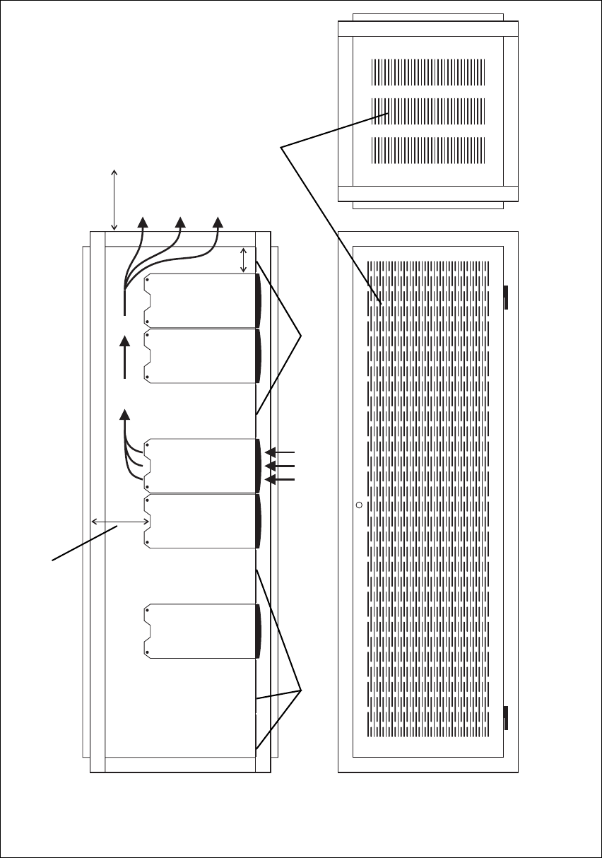
DRAFT 4
66 Installation TB9400 Installation and Operation Manual
© Tait Electronics Limited September 2011
Figure 5.1 Typical cabinet ventilation requirements
bventilation slots dairflow entry
cblanking panels eairflow exit path
8 in
(20 cm)
2 U
≥ 7 in
(≥17.5cm)
side view front view
top view
c
c
d
e
b
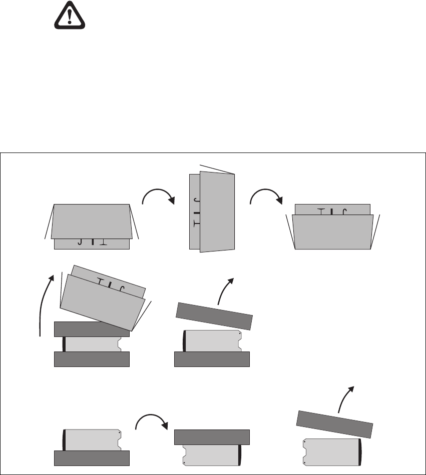
DRAFT 4
TB9400 Installation and Operation Manual Installation 67
© Tait Electronics Limited September 2011
5.2 Unpacking and Moving the Subrack
The subrack is packed in a strong corrugated cardboard carton with top and
bottom foam cushions. To prevent personal injury and damage to the
equipment, we recommend that two people unpack and move the subrack.
To remove the subrack from the carton, follow the procedure illustrated in
Figure 5.2.
Caution A subrack complete with modules can weigh up to
55 lb (25 kg), or up to 62 lb (28 kg) complete with
packaging. We recommend that you have another
person help you unpack and move the subrack. The
TBAA03-16 carrying handles will make it easier to
move the subrack once it has been unpacked. If nec-
essary, remove the modules from the subrack before
moving it (refer to “Replacing Modules” on
page 93). In all cases follow safe lifting practices.
1. Cut the tape securing the flaps at the top of the carton and fold them
flat against the sides b.
2. Rotate the carton carefully onto its side c and then onto its top d,
ensuring that none of the flaps is trapped underneath.
Figure 5.2 Unpacking the subrack
b
e
g
f
hi
cd
DRAFT 4
68 Installation TB9400 Installation and Operation Manual
© Tait Electronics Limited September 2011
3. Slide the carton upwards over the foam cushions and lift it away e.
Remove the cushion from the bottom of the subrack f.
4. Rotate the subrack and cushion carefully over the rear of the subrack
g so that it is the right way up with the cushion on top h. Remove
the cushion from the top of the subrack i.
Disposal of
Packaging If you do not need to keep the packaging, we recommend that you recycle
it according to your local recycling methods. The foam cushions are CFC-
and HCFC-free and may be burnt in a suitable waste-to-energy combustion
facility, or compacted in landfill.
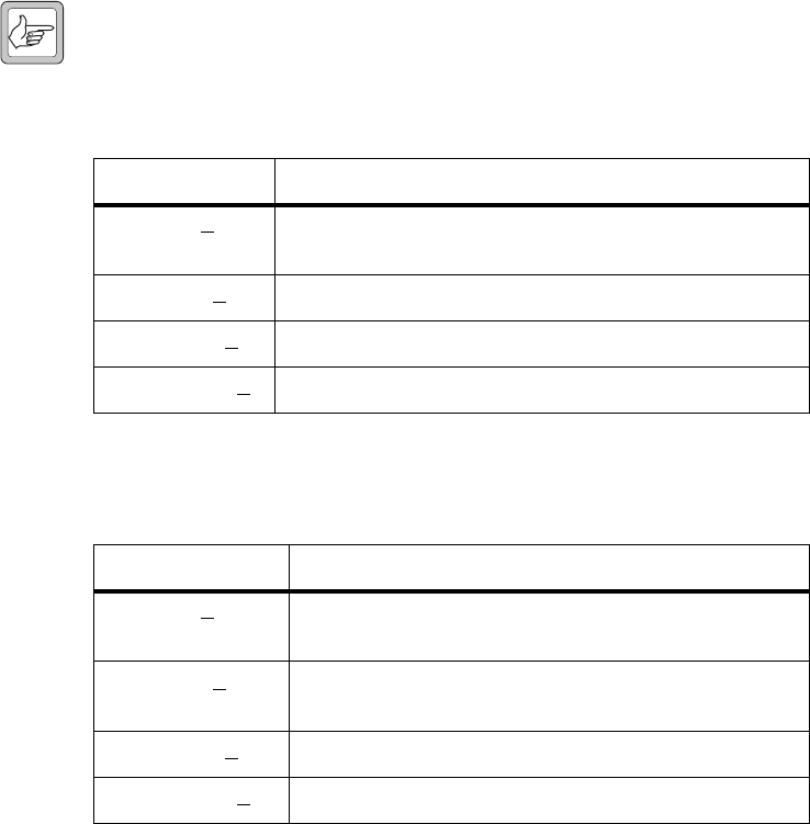
DRAFT 4
TB9400 Installation and Operation Manual Installation 69
© Tait Electronics Limited September 2011
5.3 Identifying the Equipment
You can identify the model and hardware configuration of the TB9400
modules by referring to the product code printed on labels at the rear of
each module. The meaning of each character in the product code is
explained in the tables below.
Note This explanation of product codes is not intended to suggest that
any combination of features is necessarily available in any one
product. Consult your regional Tait office for more information
regarding the availability of specific models and options.
Reciter Product
Codes
PA Product Codes
Product Code Description
T01-01103-XXXX Frequency Band and Sub-band
N = 762MHz to 870MHza (K4)
a. The actual frequency coverage in this band is:
Transmit: 762MHz to 776MHz and 850MHz to 870MHz
Receive: 792MHz to 824MHz
T01-01103-XXXX A = standard
T01-01103-XXXX A = default
T01-01103-XXXXA = default
Product Code Description
T01-01121-XXXX Frequency Band and Sub-band
N = 762MHz to 870MHza (K4)
a. The actual frequency coverage in this band when used with a K-band TB9400 reciter
is 762MHz to 776MHz and 850MHZ to 870MHz.
T01-01121-XXXX A = 50 W
B = 100 W
T01-01121-XXXX A = default
T01-01121-XXXXA = default

DRAFT 4
70 Installation TB9400 Installation and Operation Manual
© Tait Electronics Limited September 2011
PMU Product Codes Product Code Description
TBAXXXX-XXXX 3 = PMU
TBA3XXX-XXXX 0 = default
TBA3XXX-XXXX 0 = AC module not fitted
A = AC module fitted
TBA3XXX-XXXX 0 = DC module not fitted
1 = 12V DC module fitted
2 = 24V DC module fitted
4 = 48V DC module fitted
TBA3XXX-XXXX 0 = standby power supply card not fitted
1 = 12VDC standby power supply card fitted
2 = 24VDC standby power supply card fitted
4 = 48VDC standby power supply card fitted
TBA3XXX-XXXX 0 = auxiliary power supply board not fitted
1 = 12VDC auxiliary power supply board fitted
2 = 24VDC auxiliary power supply board fitted
4 = 48VDC auxiliary power supply board fitted
TBA3XXX-XXXX 0 = default
TBA3XXX-XXXX0 = default

DRAFT 4
TB9400 Installation and Operation Manual Installation 71
© Tait Electronics Limited September 2011
5.4 Initial Setting Up
Before putting the base station into service, you may want to car ry out some
basic functional testing, configuration, and tuning (if required). This section
provides an overview of these procedures:
■checking that the base station powers up correctly
■checking the basic functionality of the base station by using the tests
available in the web interface
■customizing the configuration for the intended installation and verifying
that the configuration is correct
■changing the root password (if needed - TBD)
■tuning the base station (if required).
5.4.1 Confirming Operation
Important Make sure that the RF output is connected to a suitable
attenuator or dummy load. Do not remove the load while
the PA is transmitting as this may damage the PA output
stage.
Applying Power 1. Apply power by turning on the PMU.
2. Check that the base station powers up correctly:
■The front panel display will show “Please wait” while the base
station starts up (this may take up to two minutes). When the
startup process is complete, the display will show the idle screen.
■The cooling fans in the front panel will run at full speed for a few
seconds, then run at low speed while the base station starts up, and
then assume standard operation. One or more fans may operate,
depending on the temperature of the modules.
??

DRAFT 4
72 Installation TB9400 Installation and Operation Manual
© Tait Electronics Limited September 2011
Functional Tests The following table provides an overview of the tests available using the web
interface. Refer to the Help for full details of these tests.
Tes t Notes Me nu
receiver operation requires a suitable RF source Diagnose > RF Interface > Receiver
transmitter operation requires connection to the network Diagnose > RF Interface > Transmitter
synchronized transmit checks the simulcast operation of a
channel group or the transmitters
in it
Diagnose > RF Interface > Synchronized
Transmit
ping checks the IP connection to
another device with an IP address
Diagnose > Connection > Network
NTP query checks if the NTP-based time
synchronization is working
PMU mains failure requires a DC backup supply Diagnose > Subsystems > PMU Control Tests
fan operation checks the operation of each fan
individually
Diagnose > Subsystems > Fan Tests

DRAFT 4
TB9400 Installation and Operation Manual Installation 73
© Tait Electronics Limited September 2011
5.4.2 Customizing the Configuration
The following steps provide an overview of the process used to configure
the base station with the settings it needs. Refer to the Help for detailed
information.
1. Log in to the base station (refer to “Connecting Your PC to the Base
Station” on page 46 for more details).
2. Select Configure. The base station has many different settings that can
be configured before it is put into operation, such as:
■channel configurations
■alarm control and SNMP agent
■network interfaces
■channel groups and quality of service
■channel and signaling profiles
■CWID
■miscellaneous items such as minimum battery voltages, fan
control, NTP and package servers.
3. Make the changes needed in each form and click Save.
Note We recommend that you save the configuration to your PC or
network. First make a backup copy of the configuration (which is
stored in the base station as a file), then save this file to a folder on
your PC or network. This provides a backup which can be
restored to the base station if the configuration information
becomes lost or corrupted.

DRAFT 4
74 Installation TB9400 Installation and Operation Manual
© Tait Electronics Limited September 2011
5.4.3 Changing the Root Password
The root password to the Linux operating system of the reciter is a possible
security risk. The equipment is delivered with a default password that is well
known. Knowledge of the password could be used to render the equipment
inoperable, for example by deleting files. If you are concerned about the
security risk that this poses, change the password. If Tait provides support
services, it may need to know the password.
Important If you change the password and then lose it, the equipment
must be returned to Tait. Make sure that you store the pass-
word securely and do not lose it.
To change the root password, follow these steps.
1. TBD
5.4.4 Tuning the Reciter
The K-band reciter does not require tuning.
?Procedure still to be
decided. May be tied in
with Admin password.
?
??
??
DRAFT 4
TB9400 Installation and Operation Manual Installation 75
© Tait Electronics Limited September 2011
5.5 Installing the Base Station on Site
5.5.1 Base Stations for Trunked Systems
When installing base stations that are part of a trunked system, it is very
important to observe good site engineering rules. This is especially true
when the channels are combined into a single antenna, particularly if the
receivers and transmitters also share the antenna, as in a duplexed system.
If at all possible, the RF planner should avoid frequency plans in which the
Rx to Tx spacing is an exact multiple of the trunked channel spacing, thus
forcing Tx intermodulation products to fall outside the Rx channels.
Cables and antennas should be of high quality construction. Solid shield
heliax type cables are best, but if braided shield cables must be used for short
distances, their braids must be silver-plated.
When the outputs of more than one transmitter are combined, their voltages
add, and the resulting peak envelope power is not simply the sum of their
powers, but is equal to the power of one of them multiplied by the square
of the number of sources. Cables, components, and hardware must be rated
to withstand the peak envelope power.
During the commissioning process, all transmitters should be activated together
using a diagnostic test tone, while the receiver RSSI is monitored. There
should be no perceptible increase in RSSI while the transmitters are active.
5.5.2 Equipment Required
It is beyond the scope of this manual to list every piece of equipment that
an installation technician should carry. However, the following tools are
specifically required for installing the base station:
■Pozidriv PZ3 screwdriver for the M6 screws used in the DC input
terminals on the PMU; M6 (0.25 in) screws are also used to secure the
subrack to the cabinet in factory-assembled systems
■Pozidriv PZ2 screwdriver for the M4 screws used to secure the module
retaining clamps, and for the fasteners used to secure the front panel to
the subrack
■8 mm AF spanner for the SMA connectors, and the subrack ground
connector.
You can also obtain the TBA0ST2 tool kit from your regional Tait office. It
contains the basic tools needed to install, tune, and service the base station.
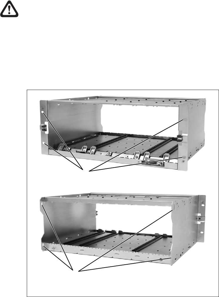
DRAFT 4
76 Installation TB9400 Installation and Operation Manual
© Tait Electronics Limited September 2011
5.5.3 Mounting the Subrack
Caution A subrack complete with modules can weigh up to
55 lb (25 kg), or up to 62 lb (28 kg) complete with
packaging. We recommend that you have another
person help you unpack and move the subrack. The
TBAA03-16 carrying handles will make it easier to
move the subrack once it has been unpacked. If nec-
essary, remove the modules from the subrack before
moving it (refer to “Replacing Modules” on
page 93). In all cases follow safe lifting practices.
1. Remove the front panel, as described in “Preliminary Disassembly”
on page 95.
2. Fit the subrack into the cabinet or rack and secure it firmly with an
M6 (0.25 in) screw, flat and spring washer in each of the four main
mounting holes b, as shown in Figure 5.3.
Figure 5.3 Subrack mounting points
bmain mounting holes - front cauxiliary mounting holes - rear
front view
rear view
b
c
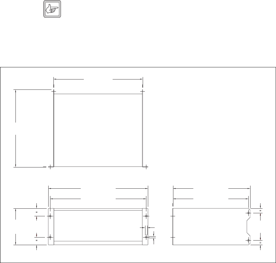
DRAFT 4
TB9400 Installation and Operation Manual Installation 77
© Tait Electronics Limited September 2011
Note If you need extra mounting security, additional mounting holes c
are provided at the rear of the subrack for auxiliary support brack-
ets.
Figure 5.4 below gives the dimensions of the subrack and its mounting
holes.
Figure 5.4 Subrack dimensions
5.25 in
(133.4 mm)
4 in
(101.6 mm)
6.96 in
(176.8 mm)
14.8 in
(375.5 mm)
19 in (482.6 mm)
17 in (432 mm)
18.3 in (465.1 mm)
0.26 in
(6.6 mm)
0.42 in
(10.6 mm)
14.7 in (373.5 mm)
14.37 in (365 mm)
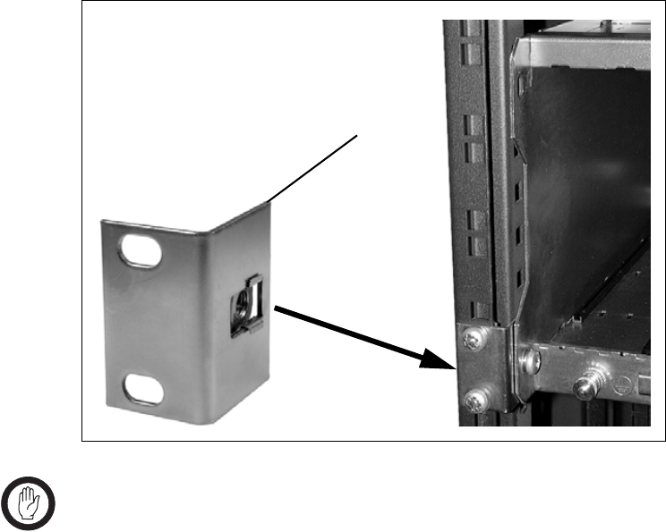
DRAFT 4
78 Installation TB9400 Installation and Operation Manual
© Tait Electronics Limited September 2011
Auxiliary Support
Bracket TBAA03-13 auxiliary support brackets can be fitted to the rear of the
subrack to provide additional mounting security. Figure 5.5 shows a standard
TBAA03-13 bracket b fitted in a typical Tait cabinet c. If you are not using
the Tait cabinet, you may have to make your own brackets to suit your
installation.
Important Yo u must fit the auxiliary support brackets if you intend to
transport a cabinet fitted with a fully built-up base station.
We also recommend that you fit the brackets under the following
conditions:
■when the installation is in an area prone to earthquakes
■when third party equipment is installed hard up underneath the base
station subrack.
General Cabling We recommend that you try to route all cables to and from the base station
along the side of the cabinet so the cooling airflow is not restricted.
Figure 5.5 Auxiliary support bracket
c
b
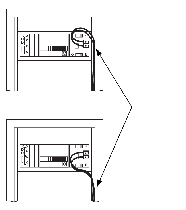
DRAFT 4
TB9400 Installation and Operation Manual Installation 79
© Tait Electronics Limited September 2011
DC Power Cabling DC power cables should be well supported so that the terminals on the
PMU and on the ends of the cables do not have to support the full weight
of the cables.
Figure 5.6 shows two recommended methods of securing these cables to
prevent straining either set of terminals.
We recommend that you fit the supplied covers to the DC terminals to
protect against accidental shorts.
Figure 5.6 DC power cabling
secure the cables to the
cabinet to support their
weight
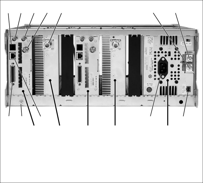
DRAFT 4
80 Installation TB9400 Installation and Operation Manual
© Tait Electronics Limited September 2011
5.6 Connecting Up the Base Station
This section provides information relevant to the task of connecting up the
various inputs and outputs of the base station.
5.6.1 Connection Overview
The connections at the rear of a dual 50 W base station are identified in
Figure 5.7. External connections are all located at the rear of the subrack.
Figure 5.7 50 W base station inputs and outputs
bserial RS-232 connectorah+ VDC input
c1 PPS input iauxiliary DC output
dexternal reference frequency input jAC mains input
eRF input 1) Ethernet interface connector
fRF output 1! subrack ground connector
g– VDC input 1@ system interface connector
a. Factory use only.
PA 1Reciter 1 PMU
bcdefgh
ij1)1!
1@
PA 2Reciter 2

DRAFT 4
TB9400 Installation and Operation Manual Installation 81
© Tait Electronics Limited September 2011
5.6.2 Connecting AC Power
The PMU is designed to accept a mains input of 88 to 264 VAC at 45 to
65 Hz. A standard 3-wire grounded socket outlet must be used to supply the
AC power. The socket outlet must be installed near the equipment and must
be easily accessible. This outlet should be connected to an AC power supply
capable of providing at least 600 W. The requirements of two typical AC
supplies are given in the following table.
Yo u r base station should come supplied with
a power supply cord to connect the male
IEC connector on the PMU to the local AC
supply. The pins of the IEC connector on
the PMU are identified at right.
Nominal Supply Current Requirementa
a. The actual current consumption of the base station will be lower than these require-
ments (refer to the Specifications Manual for more information).
Circuit Breaker/Fuse
Ratinga
115 VAC 8 A 10 A
230 VAC 4 A 6 A
ground
rear view
neutral
phase
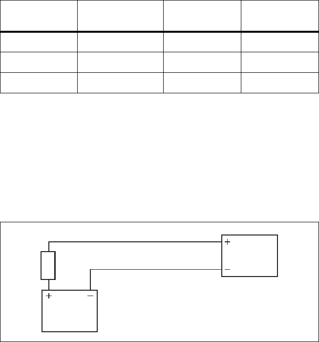
DRAFT 4
82 Installation TB9400 Installation and Operation Manual
© Tait Electronics Limited September 2011
5.6.3 Connecting DC Power
The PMU is designed to accept a nominal 12 VDC, 24 VDC or 48 VDC
input (depending on the model) with negative or positive ground. There is
a minimum DC startup threshold to prevent damaging a battery which has
little capacity left.
You must connect the DC supply from the battery to the PMU via a fuse or
DC-rated circuit breaker with a contact separation of 3 mm, and with the
appropriate rating, as shown in the table below. The DC input leads should
be of a suitable gauge to ensure less than 0.2 V drop at maximum load over
the required length of lead.
Terminate and insulate the DC input leads to protect them from accidentally
shorting to the subrack if the PMU is removed before the leads are
disconnected. Protective covers for the DC terminals are supplied with each
PMU.
We recommend a screw torque of 18 – 20 lbf · in (2 – 2.25 N · m).
Nominal Supply
Voltage
Input Voltage
Range
Circuit Breaker/
Fuse Ratinga
a. The actual current consumption of the base station will be lower than these require-
ments (refer to the Specifications Manual for more information).
Recommended
Wire Gaugeb
b. For a length of 5 ft to 6.5 ft (1.5 m to 2 m) (typical).
12 VDC 10 VDC to 16.8 VDC 60 A 2 AWG / 35 mm2
24 VDC 20 VDC to 33.6 VDC 30 A 5 AWG / 16 mm2
48 VDC 40 VDC to 60 VDC 15 A 8 AWG / 8 mm2
Figure 5.8 Recommended DC power connection
Battery
Circuit Breaker
or Fuse
PMU

DRAFT 4
TB9400 Installation and Operation Manual Installation 83
© Tait Electronics Limited September 2011
5.6.4 Connecting the Auxiliary DC Power Output
The PMU can provide an auxiliary DC output when it is fitted with the
auxiliary power supply board. This board is available with an output of
13.65 VDC, 27.3 VDC, or 54.6 VDC (depending on the model), and is
current limited to 3 A, 1.5 A or 750 mA respectively. This power supply is
permanently on as soon as the base station has finished powering up, and is
available on the auxiliary output connector on the rear panel.
You can connect multiple auxiliary power supply boards in parallel for
redundancy purposes, or to provide an output greater than 40 W. Although
no active current sharing is used, auxiliary boards connected in parallel will
current-share before reaching their power limit. The failure (or switching
off) of one auxiliary board will not load any other paralleled auxiliary boards
in the circuit.
Auxiliary DC Power
Output Cabling Network elements are supplied with a connector, as shown in Figure 5.9.
You can use this to connect the PMU’s auxiliary DC power output to
another device.
Contact your regional Ta i t office for details on the full range of wiring kits
available.
Figure 5.9 Auxiliary DC power connector
Phoenix MVSTBR2.5HC/2-ST/5.08 female

DRAFT 4
84 Installation TB9400 Installation and Operation Manual
© Tait Electronics Limited September 2011
5.6.5 Connecting RF
Important Do not remove the load from the PA while it is transmitting
as this may damage the PA output stage.
The RF input to the base station is via the marked BNC connector on the
rear panel of the reciter. The RF output is via the N-type connector on the
rear panel of the PA (refer to Figure 5.7 on page 80).
Cables and antennas should be of high quality construction. Solid shield
heliax type cables are best, but if braided shield cables must be used for short
distances, their braids must be silver-plated.
Recommendations
for Installing the PA We recommend the following installation procedures, which should protect
the PA from damage under all but the most extreme operating conditions.
1. Do not connect the PA directly to the antenna. Fit an isolator or
duplexer between the PA and the load. Fit the isolator as close as pos-
sible to the RF output connector on the PA. Do not connect any
switching equipment between the isolator and the PA, unless the
switch cannot operate while there is RF present (i.e. the base station
is transmitting).
2. Fit a surge suppressor to the antenna cabling where it enters the
building.
3. Inspect all cables and equipment connected to the base station for
defects.
Ice on the antenna, or a broken antenna, is unlikely to cause damage to the
PA.
Explanation The circuit design of the PA protects the circuitry from high VSWR. This
makes it difficult to damage the RF power device by keying the PA into a
mismatched load, or if the load deteriorates over even a short period of time
(milliseconds).
However, it is possible to damage the device if all the following conditions
happen at the same time:
■there is a step change in the PA load (for example, the load is removed)
■the PA is transmitting
■the feed line loss between the PA and the mismatch is < 1 dB.
The effect of such conditions is variable: some devices will not be destroyed,
and some may fail after repeated load interruptions.
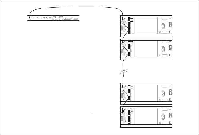
DRAFT 4
TB9400 Installation and Operation Manual Installation 85
© Tait Electronics Limited September 2011
5.6.6 Connecting an External Frequency Reference
For K4 Band, the internal frequency reference accuracy is inadequate, and
an external reference (for example, the Tait T801-4) must be used. An
external reference is also required for simulcast. The external reference
frequency can be 10 MHz or 12.8 MHz, with an input level of 300 mVpp to
5 V pp. The stability of this reference should be better than 50 parts per billion
(for non-simulcast) or ≤ 1 part per billion (for simulcast). The reciter
automatically detects the frequency of the external reference and configures
itself accordingly.
If an external reference is required, enable the external reference “Absent”
alarm (Configure > Alarms > Control).
Use a 50 Ω coaxial cable (RG58 or RG223) to connect the external
reference to the base station’s external reference frequency input. You can
daisy-chain up to eight base stations using T-junctions. The maximum
overall cable length is 30 m. Terminate the last connection with a 50 Ω load.
Figure 5.10 Daisy-chaining an external frequency reference input
50 Ω termination
maximum of eight base
station loads on one
frequency reference output
maximum overall cable
length is 30 m
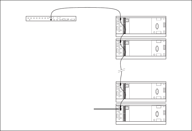
DRAFT 4
86 Installation TB9400 Installation and Operation Manual
© Tait Electronics Limited September 2011
5.6.7 Connecting a 1 PPS Source
A 1 PPS signal is required for simulcast base stations. This and the external
frequency reference can be provided, for example, by a Tait T801-4
Frequency Reference. For more information, see the T801-4 Installation
and Operation Manual (MBA-00033-xx).
Use a 50 Ω coaxial cable (RG58 or RG223) to connect the source to the
base station’s 1 PPS input. You can daisy-chain up to six base stations using
T-junctions. We recommend that the cable length between the first and last
load is kept to a minimum. This will reduce any propagation variation
between base stations. The maximum overall cable length is 30 m. Terminate
the last connection with a 50 Ω resistor, otherwise reflections of the 1 PPS
pulse may occur.
5.6.8 Ethernet Connection
The RJ-45 socket on the reciter’s rear panel provides the 10BASE-T or
100BASE-T Ethernet connection to the other devices in the network. Use
Cat-5 cable to connect this socket to the TaitNet P25 Network via a router
or switch.
If necessary, refer to “Ethernet Connector” on page 109 for a list of Ethernet
connection pin allocations.
Figure 5.11 Daisy-chaining a 1 PPS input
The longest length of cable must be between
the source and the first base station
use short lengths of cable
between each base station
maximum of six base station
loads on one 1 PPS output
50 Ω termination

DRAFT 4
TB9400 Installation and Operation Manual Installation 87
© Tait Electronics Limited September 2011
5.6.9 Connecting General Purpose Inputs and Outputs
The base station has a number of general purpose inputs and outputs. These
are connected via the 25-way D-range on the rear panel.
The pin allocations for the D-range connector are given in the following
table. Not all pins are used in this release of the base station.
Pin Signal Name Signal Type Notes
1
not used
2
3
4
5
6
7
8
9
10
11 digital in 1 input 5 V TTL logic
active low
12 digital in 2
13 + 5.2 VDC output power output maximum current 200 mA
14 digital in 3
input 5 V TTL logic
active low
15 digital in 4
16 digital in 5
17 digital in 6
18 digital in 7
19 digital in 8
20 digital in 9
21 digital in 10
22 digital in 11
23 digital in 11
24 not used
25 ground ground
external view
B
C
D
E
F
G
H
I
J
1)
1!
1@
1#
1$
1%
1^
1&
1*
1(
2)
2!
2@
2#
2$
2%
DRAFT 4
88 Installation TB9400 Installation and Operation Manual
© Tait Electronics Limited September 2011

DRAFT 4
TB9400 Installation and Operation Manual Maintenance 89
© Tait Electronics Limited September 2011
6 Maintenance
The base station is designed to be very reliable and should require little
maintenance. However, performing regular checks will prolong the life of
the equipment and prevent problems from happening.
It is beyond the scope of this manual to list every check that you should
perform on your base station. The type and frequency of maintenance
checks will depend on the location and type of your system. The checks and
procedures listed below can be used as a starting point for your maintenance
schedule.
Performance Checks We suggest you monitor the following operational parameters using the web
interface:
■VSWR
■DC input voltage, especially on transmit
■receiver sensitivity
■any temperature alarms.
These basic checks will provide an overview of how well your base station
is operating.
Reciter If an external frequency reference is not used, check UHF reciters for
frequency drift after 3 months’ service and annually thereafter. If the drift is
> 0.5 ppm, adjust the carrier frequency offset. For details, see the Help.
PA There are no special maintenance requirements for the PA.
PMU There are no special maintenance requirements for the PMU. However, we
suggest that you periodically check that the screws on the DC input
terminals are tight. They may work loose with thermal cycling. Also, if you
are using battery back-up, you should check the batteries regularly in
accordance with the manufacturer’s recommendations.
Ventilation The base station has been designed to have a front-to-back cooling airflow.
We strongly recommend that you periodically check and maintain the
ventilation requirements described in “Equipment Ventilation” on page 64
to ensure a long life and trouble-free operation for your base station.
Cooling Fans The cooling fans have a long service life and have no special maintenance
requirements. You can use the web interface to configure the base station to
generate an alarm if any of the front panel cooling fans fails. Refer to the
Help for more details.
DRAFT 4
90 Maintenance TB9400 Installation and Operation Manual
© Tait Electronics Limited September 2011

DRAFT 4
TB9400 Installation and Operation Manual Troubleshooting 91
© Tait Electronics Limited September 2011
7 Troubleshooting
Check that all front and rear connectors and cables are in place, and that
power switches are on. If problems persist, contact your regional Ta it office.
Symptom Possible Cause Action
Alarm LED red and steady
(not flashing)
The base station is in
Offline mode
Use the web interface to put the base station in
Online mode
Desired feature is not
operating
Feature license missing Check that you have the necessary feature licenses
(refer to “Licenses” on page 18 and the Help)
Feature license present but
feature is not enabled
Use the web interface to enable the feature.
Tx stuck on Tx and Rx frequencies are
the same
Reconfigure Tx and Rx with different frequencies
Power LED on front panel
is on, but keypad does not
work
Keypad is disabled Check that the keypad is enabled in the web
interface (Configure > Base Station >
Miscellaneous)
No power or LEDs on front
panel
System control bus not
connected to front panel
Check cable connections
Pins bent on 15-pin
D-range plug on front
panel
Replace or repair D-range plug
The base station appears to
make random
transmissions
CWID feature enabled No action: CWID transmissions are made according
to configuration settings
PA has low power Channel is configured to
low power
Use the web interface to check the power settings
PA may have suffered
partial damage
Replace module and send faulty module for
servicing
Test tones can’t be heard IMBE does not pass on
tones higher than 400 Hz
Ensure test tones are less than 400 Hz
Lost or forgotten base
station IP address
Procedure TBD
?
?
DRAFT 4
92 Troubleshooting TB9400 Installation and Operation Manual
© Tait Electronics Limited September 2011

DRAFT 4
TB9400 Installation and Operation Manual Replacing Modules 93
© Tait Electronics Limited September 2011
8 Replacing Modules
Caution The 100 W PA and PMU weigh between 9.3 lb
(4.2 kg) and 15.4 lb (7 kg) each. Take care when hand-
ling these modules to avoid personal injury.
Important The cooling fans are mounted on the front panel and will
only operate when the panel is fitted correctly to the front
of the subrack. To ensure adequate airflow through the base
station, do not operate it for more than a few minutes with
the front panel removed (e.g. for servicing purposes). Both
the PMU and PA modules have built-in protection mech-
anisms to prevent damage from overheating.
DRAFT 4
94 Replacing Modules TB9400 Installation and Operation Manual
© Tait Electronics Limited September 2011
8.1 Saving the Base Station’s Configuration
Before replacing a module in the base station, you should decide whether
you need to save its configuration data. If you are unsure whether you have
a record of the configuration, backup and save the configuration file before
removing any modules. Once you have replaced the module, you will be
able to restore the original configuration to the base station.
If one or more of the modules is faulty, you may be unable to save the
configuration. In this case, you will have to restore the configuration from a
back-up file. Refer to the Help for more information.
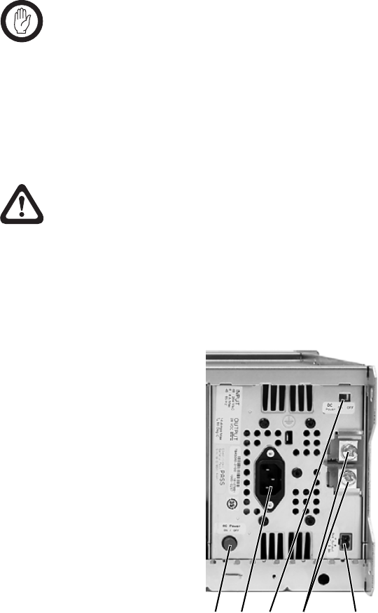
DRAFT 4
TB9400 Installation and Operation Manual Replacing Modules 95
© Tait Electronics Limited September 2011
8.2 Preliminary Disassembly
Hot-pluggable
Modules The reciter, PA and front panel are hot-pluggable and can be removed
without powering down the whole base station. These modules can also be
removed without disrupting the system control bus communications with
the other modules in the subrack.
Important Before removing a PA, first disconnect the DC input, trans-
mit forward input and transmit reverse output, followed by
the RF output. After refitting the PA, reconnect the RF
output first, followed by the transmit forward input, trans-
mit reverse output, and then the DC input.
Disconnecting the
Power If you want to disconnect the power before working on the base station,
follow these steps.
Caution Before disconnecting the battery supply leads from
the PMU, open the circuit breaker or disconnect the
supply leads from the battery.
1. Turn off the AC b and DC c switches at the rear of the PMU.
2. Also at the rear of the PMU disconnect the mains d and battery e
supply leads, and the auxiliary DC supply lead f (if fitted).
bcdef
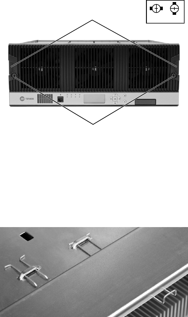
DRAFT 4
96 Replacing Modules TB9400 Installation and Operation Manual
© Tait Electronics Limited September 2011
Remove the Front
Panel 1. Using a Pozidriv PZ2 screwdriver, undo the fastener at each end of
the front panel b with a quarter turn counterclockwise.
2. Place a finger in the recess c provided at each end of the front panel
and pull the front panel away from the subrack.
Cable Retaining
Clips The cable retaining clips are used to hold cables in position at the top of the
subrack so that they do not interfere with the mounting of the front panel,
or interrupt the airflow through the base station.
If you need to remove any front panel cables, simply pull the front of the
cable retaining clip down and then slide it out from the subrack until it
reaches the end of its travel.
lockedunlocked
b
c
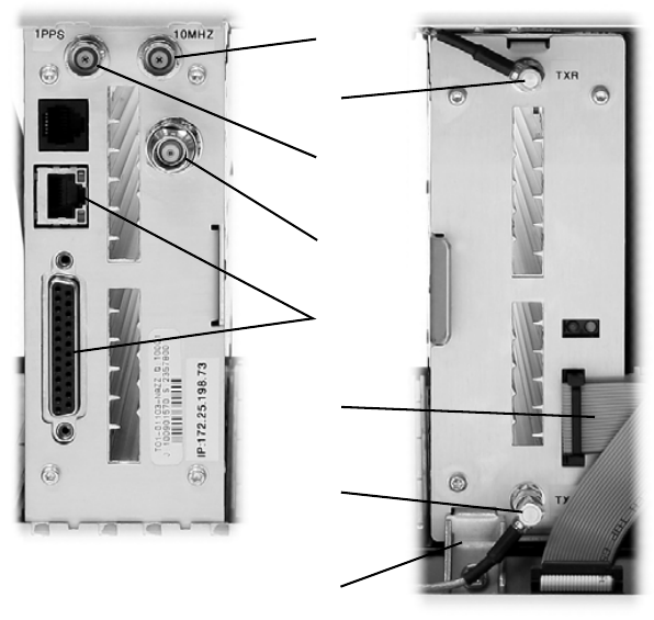
DRAFT 4
TB9400 Installation and Operation Manual Replacing Modules 97
© Tait Electronics Limited September 2011
8.3 Replacing a Reciter
Removal 1. If you have not already done so, carry out the instructions in “Pre-
liminary Disassembly” on page 95.
2. At the rear of the reciter, unplug the RF input cable b, any system
cables c, and the external reference d and 1 PPS e cables (if fitted).
3. At the front of the reciter, unplug the transmit reverse f and transmit
forward g cables, and move both cables to one side. Unplug both
ends of the system control bus cable h and remove it.
4. Loosen the screw securing the retaining clamp i and rotate the
clamp through 90° to clear the module.
5. Slide the reciter out of the subrack, taking care not to damage any of
the cables.
b
c
d
e
f
g
h
i
DRAFT 4
98 Replacing Modules TB9400 Installation and Operation Manual
© Tait Electronics Limited September 2011
Refitting 1. Slide the replacement reciter into the subrack and secure it with the
retaining clamp.
2. Reconnect all the front and rear panel cables previously disconnected.
Ensure the front panel cables are positioned correctly, and retained
where required by the cable retaining clips in the top of the subrack
(refer to “Appendix B – Inter-Module Connections” on page 111).
3. Tighten the nut on the SMA connector to a torque of 8 lbf ·in
(0.9 N·m).
4. Carry out the instructions in “Final Reassembly” on page 107.
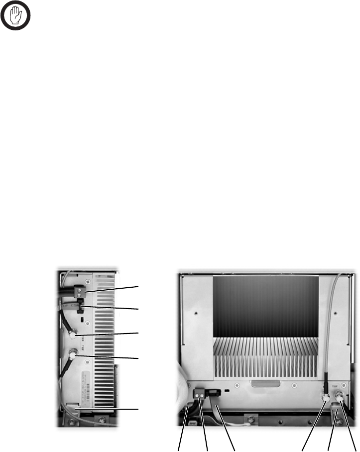
DRAFT 4
TB9400 Installation and Operation Manual Replacing Modules 99
© Tait Electronics Limited September 2011
8.4 Replacing a Power Amplifier
Important Before removing a PA, first disconnect the DC input, trans-
mit forward input and transmit reverse output, followed by
the RF output. After refitting the PA, reconnect the RF
output first, followed by the transmit forward input, trans-
mit reverse output, and then the DC input.
Removal 1. If you have not already done so, carry out the instructions in “Pre-
liminary Disassembly” on page 95.
2. At the front of the PA, unplug the DC input b, transmit forward c
and transmit reverse d cables, and move the cables to one side.
Unplug both ends of the system control bus cable e and remove it.
3. At the rear of the PA, unplug the RF output cable.
4. Loosen the screw securing the retaining clamp(s) f and rotate the
clamp(s) through 90° to clear the module.
5. Slide the PA out of the subrack, taking care not to damage any of the
cables.
Refitting 1. Slide the replacement PA into the subrack and secure it with the
retaining clamp(s).
2. At the rear of the PA, connect the RF output cable.
3. At the front of the PA, connect the transmit forward and transmit
reverse cables, followed by the DC input cable.
4. Reconnect all the other front and rear panel cables previously
disconnected. Ensure the front panel cables are positioned correctly,
and retained where required by the cable retaining clips in the top of
b
e
d
c
f
be d cff
50 W PA 100 W PA
DRAFT 4
100 Replacing Modules TB9400 Installation and Operation Manual
© Tait Electronics Limited September 2011
the subrack (refer to “Appendix B – Inter-Module Connections” on
page 111).
5. Tighten the nut on the SMA connector to a torque of 8 lbf ·in
(0.9 N·m).
6. Carry out the instructions in “Final Reassembly” on page 107.
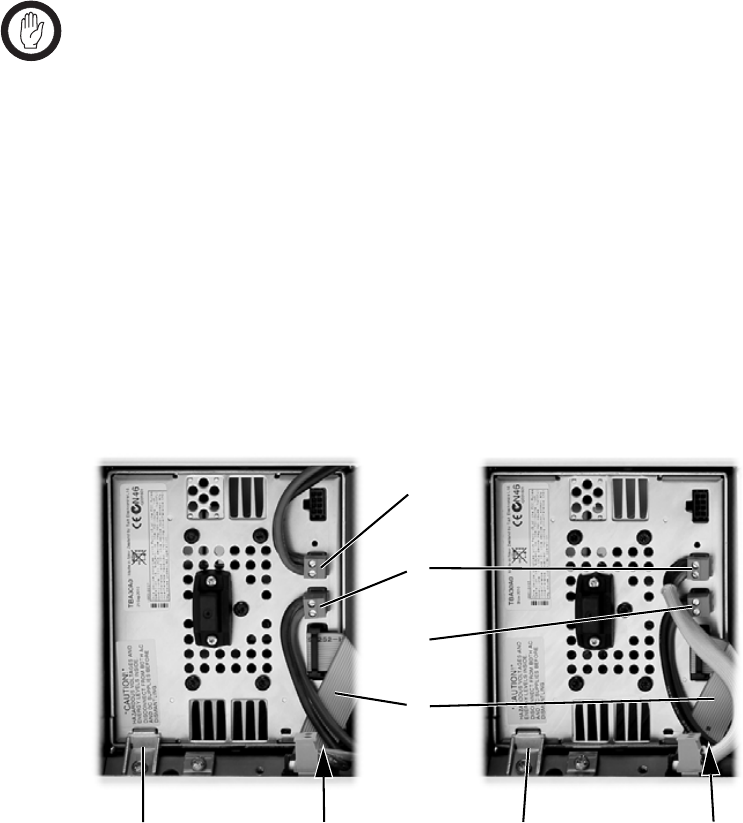
DRAFT 4
TB9400 Installation and Operation Manual Replacing Modules 101
© Tait Electronics Limited September 2011
8.5 Replacing a Power Management Unit
Important You must disconnect the AC and DC power cables before
removing the PMU from the subrack.
Removal 1. If you have not already done so, carry out the instructions in “Pre-
liminary Disassembly” on page 95.
2. At the front of the PMU, unplug and remove the output power
cable b to the subrack interconnect board. Also unplug and remove
the system control bus cable c.
3. Unplug the output power cable to the PA d and move it to one side.
4. Loosen the screws securing the retaining clamps e and rotate the
clamps through 90° to clear the module.
5. Slide the PMU out of the subrack, taking care not to damage any of
the cables.
Refitting 1. Slide the replacement PMU into the subrack and secure it with the
retaining clamps.
2. Reconnect all the front and rear panel cables previously disconnected.
Connect the DC power cables on the rear panel as shown in
Figure 5.6 on page 79. Tighten the screws to a torque of 18 – 20 lbf · in
(2 – 2.25 N · m). Ensure the front panel cables are positioned correctly,
and retained where required by the cable retaining clips in the top of
the subrack (refer to “Appendix B – Inter-Module Connections” on
page 111).
3. Carry out the instructions in “Final Reassembly” on page 107.
(obscured)
50 W base station 100 W base station
b
c
d
d
ee e
(obscured)
e

DRAFT 4
102 Replacing Modules TB9400 Installation and Operation Manual
© Tait Electronics Limited September 2011
8.6 Replacing the Front Panel Fans
The following instructions refer to Figure 8.1 on page 104.
Important You must replace each fan duct assembly in its original loca-
tion in the front panel. Each module, or pair of modules,
requires a specific type of fan duct to ensure the cooling air
flow passes directly through the modules’ heatsinks.
If a cooling fan has failed and you are fitting a replacement front panel, you
must also fit the correct type of front panel for that base station. Each type
of base station has a different combination of modules, and must use a front
panel fitted with fan ducts that match those modules.
The front panel for a 100 W base station has different fan ducts from the
front panel for a 50 W base station, as shown in Figure 8.1. In a 50 W base
station, the fan duct for reciter and PA 1 is slightly different from the duct
for reciter and PA 2. Each duct is designed to fit only in its correct position.
Removal 1. If you have not already done so, carry out the instructions in “Pre-
liminary Disassembly” on page 95.
2. Reciter and 50 W PA Fan
a. Unplug the fan from the front panel board ( b or c ).
b. Remove the four screws labeled d or e and remove the fan duct
assembly from the front panel.
c. Remove the fours screws holding the fan into the duct and
remove the fan.
3. 100 W PA Fan
d. Unplug the fan from the front panel board f.
e. Remove the four screws labeled g and remove the fan duct
assembly from the front panel.
f. Remove the fours screws holding the fan into the duct and
remove the fan.
4. PMU Fan
a. Remove the 100 W PA or reciter and 50 W PA 2 fan duct assembly
as described above.
b. Unplug the PMU fan from the front panel board h.
c. Remove the two screws labeled i and remove the PMU fan duct
assembly.
d. Remove the fours screws holding the fan into the duct and
remove the fan.

DRAFT 4
TB9400 Installation and Operation Manual Replacing Modules 103
© Tait Electronics Limited September 2011
Refitting 1. If the original fan was fitted with spacers j, refit these spacers to the
replacement fan.
2. Fit the replacement fan into the duct, routing the power wires neatly
around the body of the fan to the slot in the side of the duct, as shown
in Figure 8.1.
3. Refit the four screws securing the fan into the duct. Do not
overtighten these screws or you may distort the fan body.
4. PMU Fan
a. Refit the PMU fan duct assembly onto its mounting bosses. Note
that the two mounting tabs nearest the center fan fit over the
bosses.
b. Refit the two screws labeled i.
c. Plug the fan into the front panel board h.
d. Refit the 100 W PA or reciter and PA 2 fan duct as described
below.
5. 100 W PA Fan
a. Refit the PA fan duct assembly onto its mounting bosses. Note
that the two mounting tabs nearest the PMU fan fit over the tabs
of the PMU fan duct.
b. Refit the fours screws labeled g.
c. Plug the fan into the front panel board f.
6. Reciter and 50 W PA Fan
a. Refit the fan duct assembly onto its mounting bosses. When
refitting the duct for reciter and PA 2, note that the two mounting
tabs nearest the PMU fan fit over the tabs of the PMU fan duct.
b. Refit the fours screws labeled d or e.
c. Plug the fan into the front panel board ( b or c ).
7. Carry out the instructions in “Final Reassembly” on page 107.
Important You must connect the fans to the correct sockets on the
front panel board, as shown in Figure 8.1. If the fan con-
nections are changed, the wrong fan will be activated when
a module needs cooling. The module may then fold back
or shut down.
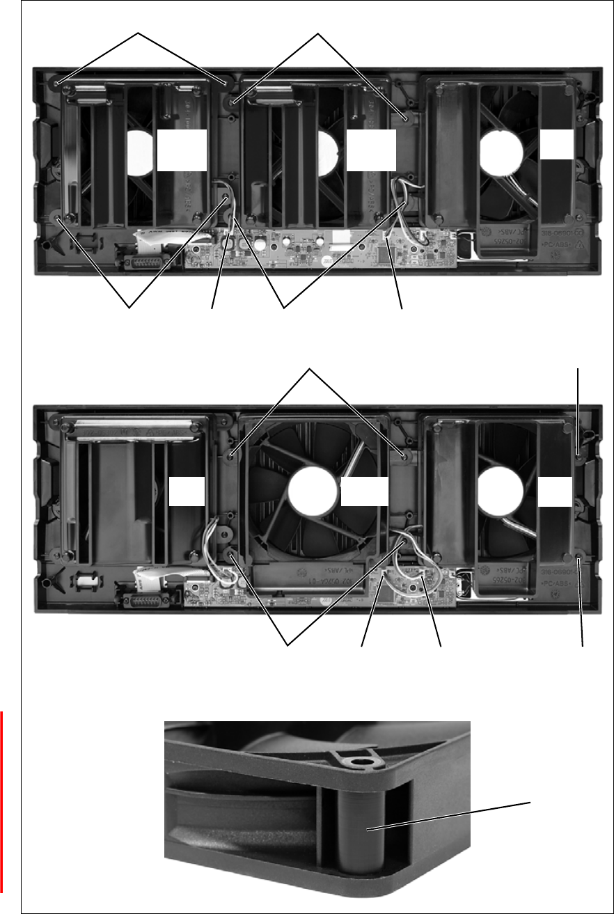
DRAFT 4
104 Replacing Modules TB9400 Installation and Operation Manual
© Tait Electronics Limited September 2011
Figure 8.1 Replacing the front panel fans
50 W base station
de
de
bc
100 W base station
gi
gf hi
j
reciter 1/
50 W PA 1
(fan 1)
reciter 2/
50 W PA 2
(fan 2)
PMU
(fan 3)
reciter
(fan 1)
PMU
(fan 3)
100 W PA
(fan 2)
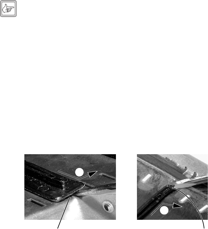
DRAFT 4
TB9400 Installation and Operation Manual Replacing Modules 105
© Tait Electronics Limited September 2011
8.7 Replacing the Module Guide Rails
The module guide rails are held in place by four hooks that fit through the
slots in the top and bottom of the subrack. There is also a locking tab which
prevents the guide rails from working loose.
Note Subracks produced from late 2008 onwards have wider slots than
earlier subracks. Guide rails designed for these wider slots will not
fit older subracks with narrow slots.
Removal 1. Bottom Guide Rails
a. Insert a small flat-blade screwdriver under the front end of the
guide rail and lift it slightly b. This will ensure the small locking
tab is clear of the slot in the subrack.
b. While holding the front end of the guide rail up, pull the guide
rail towards the front of the subrack c and lift it clear of the slots.
2. Top Rails
a. Insert a small flat-blade screwdriver under the rear end of the
guide rail and lift it slightly d. This will ensure the small locking
tab is clear of the slot in the subrack.
b. While holding the rear end of the guide rail up, pull the guide rail
towards the rear of the subrack e and lift it clear of the slots.
Refitting 1. Bottom Guide Rails
a. With the locating hooks pointing towards the rear of the subrack,
insert the hooks into the slots in the subrack.
b. Push the guide rail towards the rear of the subrack until you hear
the locking tab “click” into place.
2. Top Guide Rails
a. With the locating hooks pointing towards the front of the subrack,
insert the hooks into the slots in the subrack.
b. Push the guide rail towards the front of the subrack until you hear
the locking tab “click” into place.
bottom guide rail top guide rail
b
c
d
e
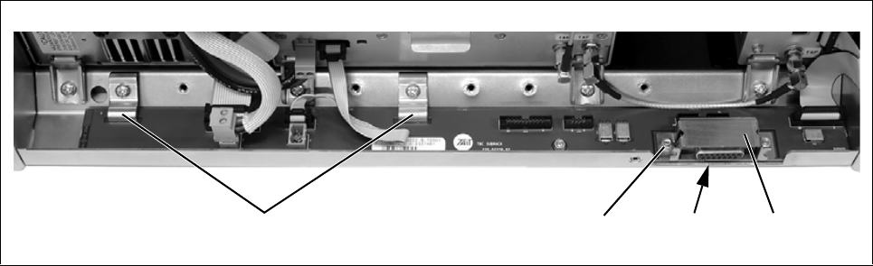
DRAFT 4
106 Replacing Modules TB9400 Installation and Operation Manual
© Tait Electronics Limited September 2011
8.8 Replacing the Subrack Interconnect Board
Removal 1. If you have not already done so, carry out the instructions in “Pre-
liminary Disassembly” on page 95.
2. Disconnect any system control bus cables and DC power cables from
the subrack board.
3. Remove the three M3 nuts and spring washers b securing the right
end of the board to the subrack.
4. Remove the D-range cover c.
5. Remove the two retaining clamps d securing the left end and centre
of the board.
6. Remove the board.
Refitting 1. If previously removed, replace the insulator e.
2. Refit the board and D-range cover, and secure with the M3 nuts and
spring washers. Replace the two retaining clamps.
3. Reconnect the system control bus cables and reciter DC cables as
shown in “Appendix B – Inter-Module Connections” on page 111.
Figure 8.2 Replacing the subrack interconnect board
becdx3
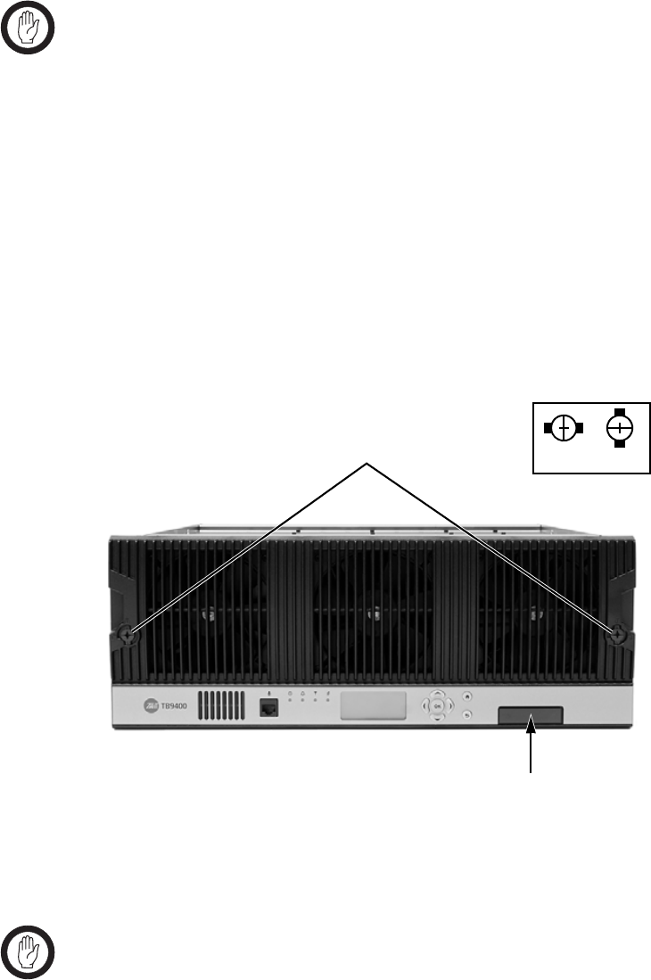
DRAFT 4
TB9400 Installation and Operation Manual Replacing Modules 107
© Tait Electronics Limited September 2011
8.9 Final Reassembly
Important You must fit the correct type of front panel to your base sta-
tion. The different types of front panel and fan ducts are
explained in “Replacing the Front Panel Fans” on
page 102.
1. Before fitting the front panel, ensure that all cables are secured and
positioned correctly so they are clear of the fan ducts (refer to
“Appendix B – Inter-Module Connections” on page 111). Other-
wise the panel may not fit properly, or you may damage the cables.
2. Refit the Front Panel
a. Ensure that the fasteners b are in the unlocked position.
b. Fit the front panel onto the locating pegs on the subrack.
c. Secure each fastener with a quarter turn clockwise.
d. Push the self-aligning D-range connector c fully in.
3. Before powering up the base station, check that all power, RF and
system cables are connected correctly and securely at the rear of the
base station.
Important When refitting modules, make sure they are fitted correctly
into the subrack and all retaining clamps are securely tight-
ened. The recommended torque for the retaining clamp
screws is 17 lbf ·in (1.9 N·m). As well as holding the modules
in place, the retaining clamps push the modules hard against
the rear rail of the subrack to ensure a good ground connec-
tion between the modules and the subrack.
lockedunlocked
b
c
DRAFT 4
108 Replacing Modules TB9400 Installation and Operation Manual
© Tait Electronics Limited September 2011
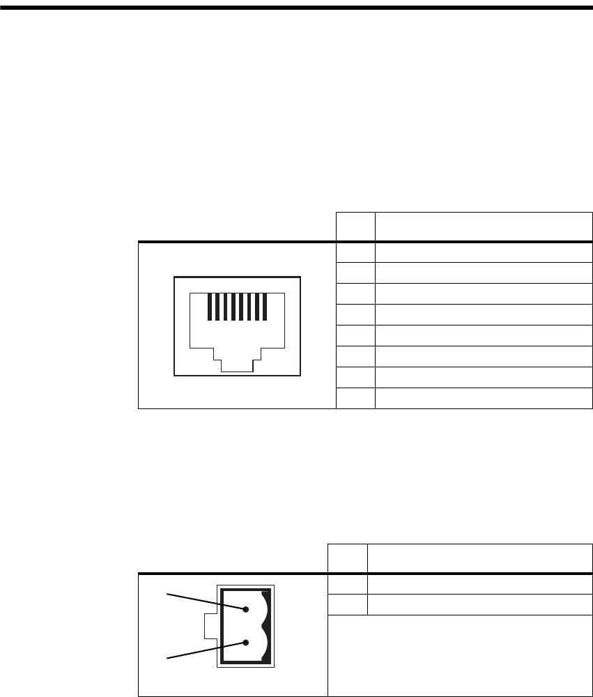
DRAFT 4
TB9400 Installation and Operation Manual Appendix A – Interface Pin Allocations 109
© Tait Electronics Limited September 2011
Appendix A – Interface Pin Allocations
System Interface Connector
For the pin allocations for the system interface D-range connector, see
“Connecting General Purpose Inputs and Outputs” on page 87.
Ethernet Connector
PMU Auxiliary DC Output
The pin allocations for the auxiliary DC output on the PMU are given in
the following table.
Pin Description
1 transmit data +
2 transmit data –
3 receive data +
4 not connected
5 not connected
6 receive data –
7 not connected
8 not connected
12345678
external view
Pin Description
1 + V output
2 ground
2-pin connector - external view
b
c
DRAFT 4
110 Appendix A – Interface Pin Allocations TB9400 Installation and Operation Manual
© Tait Electronics Limited September 2011
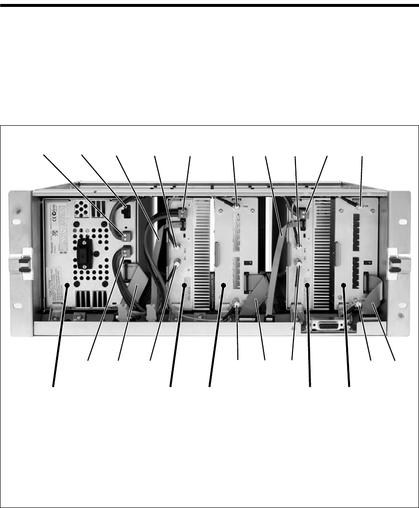
DRAFT 4
TB9400 Installation and Operation Manual Appendix B – Inter-Module Connections 111
© Tait Electronics Limited September 2011
Appendix B – Inter-Module Connections
Dual 50 W Base Station
The connections between modules at the front of a dual 50 W base station
are shown below.
DC Supply PA 1 is powered by a direct connection from the PMU. The other modules
in the subrack are powered from the PMU via the subrack interconnect
board. The DC supply to the reciters is via the system control bus ribbon
cable.
Dual 50 W base station inter-module connections
b28 VDC output for PA 1 gtransmit reverse input
cnot used hsystem control bus and 28 VDC input
dsystem control bus itransmit forward output
etransmit reverse output jtransmit forward input
f28 VDC input 1) 28 VDC output to subrack interconnect board
reciter 2PMU reciter 1PA 1PA 2
b d e f gdefg
hijhijd1)
c
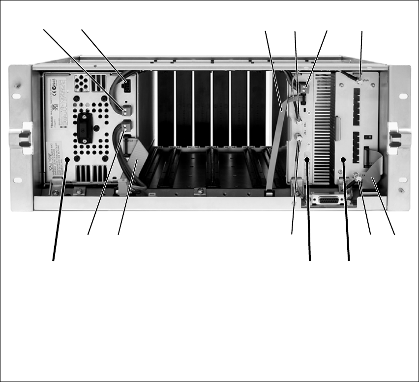
DRAFT 4
112 Appendix B – Inter-Module Connections TB9400 Installation and Operation Manual
© Tait Electronics Limited September 2011
Single 50 W Base Station
The connections between modules at the front of a single 50 W base station
are shown below.
DC Supply The PA is powered by a direct connection from the PMU. The other
modules in the subrack are powered from the PMU via the subrack
interconnect board. The DC supply to the reciter is via the system control
bus ribbon cable.
Single 50 W base station inter-module connections
b28 VDC output for PA gtransmit reverse input
cnot used hsystem control bus and 28 VDC input
dsystem control bus itransmit forward output
etransmit reverse output jtransmit forward input
f28 VDC input 1) 28 VDC output to subrack interconnect board
PMU reciter
PA
b defg
hijd1)
c
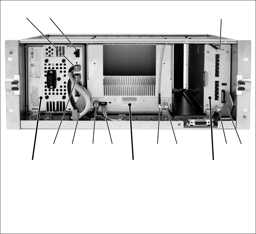
DRAFT 4
TB9400 Installation and Operation Manual Appendix B – Inter-Module Connections 113
© Tait Electronics Limited September 2011
100 W Base Station
The connections between modules at the front of a 100 W base station are
shown below.
DC Supply The PA is powered by a direct connection from the PMU. The reciter is
powered from the PMU via the subrack interconnect board and system
control bus ribbon cable.
100 W base station inter-module connections
b28 VDC output to subrack interconnect board gtransmit forward input
cnot used htransmit reverse output
dtransmit reverse input isystem control bus
esystem control bus and 28 VDC input j28 VDC input
ftransmit forward output 1) 28 VDC output for PA
PMU reciter
PA
b
ijh
d
efgi1)
c
DRAFT 4
114 Appendix B – Inter-Module Connections TB9400 Installation and Operation Manual
© Tait Electronics Limited September 2011

DRAFT 4
TB9400 Installation and Operation Manual TaitNet P25 Glossary 115
© Tait Electronics Limited September 2011
TaitNet P25 Glossary
This glossary contains an alphabetical list of terms and abbreviations related
to the TaitNet P25 network and the TB9400 base station.
A
ADC Analog-to-Digital Converter. A device for converting an analog signal to a
digital signal that represents the same information.
ANI Automatic Number Identification. A service that provides the receiver of a
call with a numerical identifier or alphanumeric label of the caller.
APCO The Association of Public Safety Communications Officials in the United
States. The APCO Project 25 standards committee defined the P25 digital
radio standard. The standard is often referred to as APCO or P25.
ARP Address Resolution Protocol is an IP protocol used to map IP network
addresses to the hardware addresses used by a data link protocol.
B
base station A radio receiver and transmitter that is located in a specific place (at a site)
that enables a two-way radio to communicate with a dispatcher or over a
larger range with other two-way radios. Specifically, Tait TB9400
equipment in a subrack.
battery protection
mode A PMU enters battery protection mode when it has AC power but its DC
power is below the configured power shutdown voltage. In battery
protection mode, the PMU will shut down to protect the battery if it loses
AC power.
bearer network Telecom equipment that is used to carry user data.
BER Bit Error Rate. A measure of the quality of digital transmission, expressed as
a percentage. The BER indicates the proportion of errors to correctly
received digits in a received signal.
DRAFT 4
116 TaitNet P25 Glossary TB9400 Installation and Operation Manual
© Tait Electronics Limited September 2011
C
C4FM Compatible Four-level Frequency Modulation. A modulation scheme
defined in the P25 CAI standard for 12.5 kHz bandwidth.
CAI Common Air Interface. The over-the-air data formats and protocols defined
by the APCO P25 committee.
call A complete exchange of information between two or more parties. A call
requires a receive signal path and a transmit signal path. In conventional
systems, a call is an over, but in trunked systems, a call may be a conversation,
made up of a number of overs.
Cartesian Loop The reciter’s RF output is fed to the PA through the transmit forward path.
A coupled signal from the PA’s RF output is fed back to the reciter through
the transmit reverse path. The reciter uses this feedback through a Cartesian
Loop to linearize the RF amplification system. Linearization is required to
accurately transmit complex waveforms which vary in frequency and
amplitude, such as those used in P25 Phase 2.
central voting Voting that is centralized at one member of the channel group.
channel 1. A path through which signals can flow.
2. In the RF domain, a frequency pair (or just a single frequency in a simplex
system).
3. A set of configuration information that defines the frequency pair and
other related settings (a channel configuration). “Channel” has this meaning
in the web interface.
channel group A single logical channel consisting of a set of base stations. The members of
a channel group are linked by an IP network and share a common multicast
IP address.
channel profile A named group of configuration settings that help to define the properties
of a channel. Each channel in the channel table must have a channel profile
assigned to it.
channel spacing The bandwidth that a channel nominally occupies. If a base station has a
channel spacing of 12.5 kHz, there must be a separation of at least 12.5 kHz
between its operating frequencies and those of any other equipment.
channel table The base station’s database of channel configurations.
CODEC A device which combines analog-to-digital conversion (coding) and digital-
to-analog conversion (decoding).
DRAFT 4
TB9400 Installation and Operation Manual TaitNet P25 Glossary 117
© Tait Electronics Limited September 2011
community
repeater Repeater that is shared by several user groups.
configuration file Consists of all the configuration settings needed for a base station, stored as
a file.
conventional
network Systems that do not have centralized management of channel access. System
operation is entirely controlled by system end users.
CWID Continuous Wave Identification is a method of automatically identifying the
base station using a Morse code. Continuous wave means transmission of a
signal with a single frequency that is either on or off, as opposed to a
modulated carrier.
D
DAC Digital-to-Analog Converter. A device for converting a digital signal to an
analog signal that represents the same information.
DDC Digital Down Converter. A device which converts the digitized IF signal of
the receiver down to a lower frequency (complex baseband) to suit the DSP.
dispatcher A person who gives official instructions by radio to one or more SU users.
distributed voting Voting for the best RF signal that is carried out separately by each channel
group member using the same voting algorithm.
dotted quad A method for writing IPv4 addresses. The form is DDD.DDD.DDD.DDD
where DDD is an 8-bit decimal number.
downlink The transmission path from fixed equipment to SUs.
DSP Digital Signal Processor.
duplex Providing transmission and reception in both directions simultaneously.
duty cycle Used in relation to the PA, it is the proportion of time (expressed as a
percentage) during which the PA is transmitting.

DRAFT 4
118 TaitNet P25 Glossary TB9400 Installation and Operation Manual
© Tait Electronics Limited September 2011
E
EIA Electronic Industries Alliance. Accredited by the American National
Standards Institute (ANSI) and responsible for developing
telecommunications and electronics standards in the USA.
EMC Electromagnetic Compatibility. The ability of equipment to operate in its
electromagnetic environment without creating interference with other
devices.
ETSI European Telecommunications Standards Institute. The non-profit
organization responsible for producing European telecommunications
standards.
F
failsoft mode An optional operational mode of TaitNet P25 trunked networks. It comes
into effect when the channel group loses all connection to the trunking site
controller.
FCC Federal Communications Commission. The FCC is an independent United
States government agency that regulates interstate and international radio
communications.
feature code The alphanumeric code used to identify a feature set.
feature set A function or mode of operation of the base station which can be enabled
or disabled using the web interface. Each feature set requires a license to be
purchased from Ta it before it can be enabled.
feature license key The unique set of digits belonging to a license which is programmed into
the base station to enable a feature set.
fill-in receiver An additional receiver placed within the coverage area of a base station to
receive SU transmissions that are too weak to be received by that base
station.
FLASH Electrically block-erasable and programmable read-only memory.
FM Frequency Modulation. Often used as an adjective to denote analog radio
transmission.
DRAFT 4
TB9400 Installation and Operation Manual TaitNet P25 Glossary 119
© Tait Electronics Limited September 2011
frequency band The range of frequencies that the equipment is capable of operating on.
front panel The cover over the front of the base station containing the indicator LEDs,
four-line LCD display, user controls and cooling fans.
G
gating The process of opening and closing the receiver gate. When a valid signal is
received, the receiver gate opens, letting the signal through.
group call A call that is sent to more than one SU simultaneously.
H
heartbeat message A message whose purpose is to indicate to the receiver that the sender is
operational.
hiccup mode Many power supplies switch off in the event of a short-circuit and try to start
again after a short time (usually after a few seconds). This “hiccup”-type of
switching off and on is repeated until the problem is eliminated.
holdover mode A simulcast base station can enter holdover mode when it loses its 1 PPS
pulse. Holdover mode temporarily maintains synchronization by phase-
locking the transmit clock to the external frequency reference.
hostname The unique name by which a network element is known on the network.
hub A unit for connecting hosts together. It sends all incoming Ethernet packets
to all the other hosts.
hysteresis The difference between the upper and lower trigger points. For example,
the receiver unmutes when the upper trigger point is reached, but will mute
again until the level falls to the lower trigger point. An adequate hysteresis
prevents the receiver gate from repeatedly muting and unmuting when the
level varies around the trigger point.

DRAFT 4
120 TaitNet P25 Glossary TB9400 Installation and Operation Manual
© Tait Electronics Limited September 2011
I
I2CA bi-directional two-wire serial bus which is used to connect integrated
circuits (ICs). I2C is a multi-master bus, which means that multiple chips can
be connected to the same bus, and each one can act as a master by initiating
a data transfer. Used in the TB9400 for communications between reciter 1
and the PMU.
IMBE Improved Multiband Excitation. A voice compression technology patented
by Digital Voice Systems, Inc and used in the vocoders of P25 radios.
impairment A measure of signal quality used in channel group voting. Impairment is
inversely related to signal quality. The lowest impairment (0) indicates the
highest signal quality. The highest impairment (15) indicates the worst signal
quality.
inbound Describes the direction of a signal: from an SU over the air interface to the
fixed station.
inhibit A control command that can be sent across the CAI to inhibit an SU. An
inhibited SU appears to the user as if it is powered off.
IP Internet Protocol is a protocol for sending data packets between hosts.
isolator A passive two-port device which transmits power in one direction, and
absorbs power in the other direction. It is used in a PA to prevent damage
to the RF circuitry from high reverse power.
K
kernel The core executable of an operating system.
L
LAN Local Area Network. A computer network that interconnects computers in
a limited area, such as a single building or group of buildings.
LDU Link Data Unit. Voice calls are sent over the CAI as a series of LDUs.
LED Light Emitting Diode. Also the screen representation of a physical LED.

DRAFT 4
TB9400 Installation and Operation Manual TaitNet P25 Glossary 121
© Tait Electronics Limited September 2011
license Some operational functions of the base station are controlled by licenses.
Purchasing a license from Ta i t allows you to enable the feature set which
includes the required functionality.
LSM Linear Simulcast Modulation is a proprietary modulation scheme designed
to give optimal performance in simulcast systems, compared to that
obtainable using C4FM.
M
marshalling
duration The length of time that the voice stream needs to travel from the central
voter to the furthest channel group member. The fixed marshalling duration
parameter includes the time needed to fill the transmit buffer to the required
level.
master The channel group master is the member with the control connection to
the trunking site controller.
multicast group The group of hosts associated with a specific IP multicast address.
multicast IP address An IP address that refers to a group of hosts rather than a single host. These
hosts will all accept packets with this IP address.
mute Prevents audio from being passed to the radio’s speaker.
N
NAC Network Access Code. The 12 most significant bits of the network identifier
information that precedes every packet sent on the CAI. The NAC
identifies which network the data belongs to, allowing base stations and
mobiles to ignore packets belonging to interfering networks.
NAT Network Address Translation allows the use of a single IP address for a whole
network of computers. A NAT sits between the public Internet and the
network it serves, and works by rewriting IP addresses and port numbers in
IP headers on the fly so the packets all appear to be coming from (or going
to) the single public IP address of the NAT device instead of the actual
source or destination.
network element Any device that is network-connected. A TaitNet digital network consists
of a number of network elements. The TB9400 base station is a network
element designed and manufactured by Tait.

DRAFT 4
122 TaitNet P25 Glossary TB9400 Installation and Operation Manual
© Tait Electronics Limited September 2011
NTP Network Time Protocol is a protocol and software implementation for
synchronizing the clocks of computer systems across a network. An NTP
server obtains the correct time from a time source and sets the local time in
each connected computer.
O
octet A set of 8 bits.
Offline mode A mode of operation in which active service is suspended so that special
operations can be carried out, such as programming in a new configuration
or carrying out invasive diagnostic tests.
Online mode The normal operating mode of the base station.
outbound Describes the direction of a signal: from a fixed station over the air interface
to an SU.
over A single transmission, which begins when a user presses PTT and ends when
the user stops pressing.
P
P25 Project 25. A suite of standards and requirements endorsed by the TIA and
intended for digital public safety radio communications systems.
PA The Power Amplifier is a base station module that boosts the exciter output
to the required transmit level.
PCB Printed Circuit Board.
PMU The Power Management Unit is a module in the base station that provides
power to the subrack and monitors power conditions.
preamble A well-defined signal that is transmitted at the beginning of digital P25 calls
to facilitate downlink voting and to allow the transmit buffer to fill.
privileges A set of access rights to the web interface functions. There are Guest,
Maintainer, and Administrator privileges.
DRAFT 4
TB9400 Installation and Operation Manual TaitNet P25 Glossary 123
© Tait Electronics Limited September 2011
Project 25 A project set up by APCO (the Association of Public Safety
Communications Officials), together with other US governmental
organizations, to develop standards for interoperable digital radios to meet
the needs of public safety users.
PSTN Public Switched Telephone Network: the public telephone network.
PTT Push To Talk. The button on an SU that keys the transmitter.
Q
QoS Quality Of Service. A router feature that gives real-time data such as voice
calls priority over other data.
R
receiver number A unique number assigned to the members of a channel group.
reciter A module of a base station that provides both receiver and exciter
functionality.
repeater talkaround Allows the SU user to bypass repeater operation and so communicate
directly with other SUs. While repeater talkaround is active, all transmissions
are made on the receive frequency programmed for the channel.
RISC Reduced Instruction Set Computer. A type of microprocessor that
recognizes a relatively limited number of instructions. The reciter’s control
board has a RISC microprocessor.
router A router is an internetwork packet switch that switches data packets from an
input interface to an output interface. The interfaces can be of different
types.
RS-232 A protocol for serial communications between a DTE (data terminal
equipment) and a DCE (data communications equipment) device.
RS-485 An updated version of the RS-232 protocol for serial communications
between multiple devices.
RSSI Received Signal Strength Indicator is a level that indicates the strength of the
received signal.
DRAFT 4
124 TaitNet P25 Glossary TB9400 Installation and Operation Manual
© Tait Electronics Limited September 2011
RTP Real Time Protocol is an Internet protocol that supports the real-time
transmission of voice and data.
Rx Receiver.
S
satellite voter A channel group member that has delegated voting activity to a central
voter.
SAW filter Surface Acoustic Wave filter. A band pass filter that can be used to filter both
RF and IF frequencies. A SAW filter uses the piezoelectric effect to turn the
input signal into vibrations that are turned back into electrical signals in the
desired frequency range.
selectivity The ability of a radio receiver to select the wanted signal and reject
unwanted signals on adjacent channels (expressed as a ratio).
sensitivity The sensitivity of a radio receiver is the minimum input signal strength
required to provide a usable signal.
signaling profile A named set of configuration items related to signaling that can be applied
to any channel.
simplex Able to provide transmission and reception in only one direction at a time.
simulcast The simultaneous broadcast by more than one transmitter of the same signal
on the same frequency.
SINAD Signal plus Noise and Distortion is a measure of signal quality. It is the ratio
of (signal + noise + distortion) to (noise + distortion). A SINAD of 12 dB
corresponds to a signal-to-noise ratio of 4:1.
site 1. The base station equipment at a particular location. This includes power
supplies, transmitters, receivers, network interfaces and controllers.
2. The location of that equipment.
skew A measure used in centrally voted channel groups. If a voice stream arrives
at the central voter 20 ms later than the first voice stream from the same SU,
it is said to have a skew of 20 ms.
DRAFT 4
TB9400 Installation and Operation Manual TaitNet P25 Glossary 125
© Tait Electronics Limited September 2011
SMR Specialized Mobile Radio. A communications system used by police,
ambulances, taxis, trucks and other delivery vehicles.
SNMP Simple Network Management Protocol. A protocol used (for example) by
the trunking site controller to monitor the status of the channel group and
its members.
SSRC Synchronization source. The SSRC is a large number specified by the
trunking controller in its connection message. It uniquely identifies voice
streams sent from the master base station.
SU Subscriber Unit. The term used in the APCO P25 standard documents for
a two-way radio (generally a mobile or a portable radio) conforming to the
CAI specifications.
supplementary
service A term used in the P25 standards. It refers to a group of services that is
additional to the basic service that a telecommunications network provides.
Examples include encryption and SU monitoring.
system control bus Provides the following physical paths in a TB9400 base station:
■I2C and RS-485 communications between the modules in the subrack
■fan power from the PMU
■power connections for the reciter and front panel.
T
Tai tN et Brand name for any PMR network designed and manufactured by Tait
Electronics Limited.
TaitNet P25 network A set of Tait base stations interconnected by an IP network that can carry
voice and data traffic.
TB9400 Base Station A P25-compliant base station consisting of the equipment necessary to
receive and transmit on one channel. Generally, this means a reciter, a PA,
and a PMU. Often abbreviated to TB9400 or base station.
TCCP Trunking Channel Control Protocol. A proprietary protocol operating over
IP for the exchange of channel control messages between a base station and
a trunking site controller.
TCP Transmission Control Protocol. A complex protocol on top of IP for
sending reliable streams of data with flow control.
DRAFT 4
126 TaitNet P25 Glossary TB9400 Installation and Operation Manual
© Tait Electronics Limited September 2011
TELCO Telephone company.
TIA Telecommunications Industry Association
toggle Describes the switching between two states. If something is on, toggling it
turns it off. If it is off, toggling it turns it on.
tone A sound wave of a particular frequency.
TSBK A Trunking Signaling Block is an over-the-air message format used in digital
P25 mode for setting up trunked calls and for supplementary services such
as messaging and status updates.
Tx Trans m itter.
U
UDP User Datagram Protocol. A simple protocol on top of IP for sending streams
of data.
uninhibit A control command that can be sent across the CAI to restore an inhibited
SU to normal functioning.
uplink The transmission path from SUs to fixed equipment.
UTC Coordinated Universal Time (word order from French). An international
time standard that has replaced Greenwich Mean Time.
V
valid signal A signal that the receiver unmutes to. A signal is valid, for example, when it
is strong enough to be decoded and when it has the specified NAC.
voice stream A digitized voice signal that passes through the main switch.
VoIP Voice over IP. The name for the technology that puts speech signals in
packets and then routes them over an IP backbone network.
voting The systematic sampling of a group of channels for the channel with the
greatest signal strength. Voting provides wide-area coverage and ensures that
DRAFT 4
TB9400 Installation and Operation Manual TaitNet P25 Glossary 127
© Tait Electronics Limited September 2011
as the user moves throughout the coverage area the strongest channel is
always available for a call.
VPN Virtual Private Network. A private communications network used to
communicate confidentially over a non-private network.
VSWR Voltage Standing Wave Ratio is the ratio of the maximum peak voltage
anywhere on the transmission line to the minimum value anywhere on the
transmission line. A perfectly matched line has a VSWR of 1:1. A high ratio
indicates that the antenna subsystem is poorly matched.
W
watchdog A circuit that checks that the system is still responding. If the system does
not respond (because the firmware has locked up), the circuit generally resets
the system.
DRAFT 4
128 TaitNet P25 Glossary TB9400 Installation and Operation Manual
© Tait Electronics Limited September 2011

DRAFT 4
TB9400 Installation and Operation Manual 129
© Tait Electronics Limited September 2011
Tait Software License Agreement
This Software License Agreement ("Agreement")
is between you (“Licensee”) and Tait Electronics
Limited (“Tait").
By using any of the Software items embedded and
pre-loaded in the related Tait Designated Product,
included on CD, downloaded from the Tait web-
site, or provided in any other form, you agree to
be bound by the terms of this Agreement. If you
do not agree to the terms of this Agreement, do
not install or use any of the Software. If you install
or use any of the Software, that will be deemed to
be acceptance of the terms of this Agreement.
For good and valuable consideration, the parties
agree as follows:
Section 1 DEFINITIONS
“Confidential Information”
means all or any
information supplied to or received by Licensee
from Tait, whether before or after installation or
use and whether directly or indirectly pertaining
to the Software and Documentation supplied by
Tait, including without limitation all information
relating to the Designated Products, hardware,
software; copyright, design registrations, trade-
marks; operations, processes, and related business
affairs of Tait; and including any other goods or
property supplied by Tait to Licensee pursuant to
the terms of this Agreement.
“Designated Products”
means products pro-
vided by Tait to Licensee with which or for which
the Software and Documentation is licensed for
use.
“Documentation”
means product and soft-
ware documentation that specifies technical and
performance features and capabilities; user, oper-
ation, and training manuals for the Software; and
all physical or electronic media upon which such
information is provided.
“Executable Code”
means Software in a form
that can be run in a computer and typically refers
to machine language, which is comprised of
native instructions the computer carries out in
hardware. Executable code may also refer to pro-
grams written in interpreted languages that
require additional software to actually execute.
“Intellectual Property Rights”
and
“Intel-
lectual Property”
mean the following or their
substantial equivalents or counterparts, recog-
nized by or through action before any govern-
mental authority in any jurisdiction throughout
the world and including, but not limited to all
rights in patents, patent applications, inventions,
copyrights, trademarks, trade secrets, trade names,
and other proprietary rights in or relating to the
Software and Documentation; including any
adaptations, corrections, de-compilations, disas-
semblies, emulations, enhancements fixes, modi-
fications, translations and updates to or derivative
works from, the Software or Documentation,
whether made by Tait or another party, or any
improvements that result from Tait processes or,
provision of information services.
“Licensee”
means any individual or entity that
has accepted the terms of this License.
“Open Source Software”
means software
with freely obtainable source code and license for
modification, or permission for free distribution.
“Open Source Software License”
means
the terms or conditions under which the Open
Source Software is licensed.
“Person”
means any individual, partnership,
corporation, association, joint stock company,
trust, joint venture, limited liability company,
governmental authority, sole proprietorship, or
other form of legal entity recognized by a govern-
mental authority.
“Security Vulnerability”
means any flaw or
weakness in system security procedures, design,
implementation, or internal controls that if exer-
cised (accidentally triggered or intentionally
exploited) could result in a security breach such
that data is compromised, manipulated, or stolen,
or a system is damaged.
“Software”
(i) means proprietary software in
executable code format, and adaptations, transla-
tions, de-compilations, disassemblies, emulations,
or derivative works of such software; (ii) means
any modifications, enhancements, new versions
and new releases of the software provided by Tait;
and (iii) may contain one or more items of soft-
ware owned by a third-party supplier. The term
"Software" does not include any third-party soft-
ware provided under separate license or not
licensable under the terms of this Agreement.
“Source Code”
means software expressed in
human readable language necessary for under-
standing, maintaining, modifying, correcting, and
enhancing any software referred to in this Agree-
ment and includes all states of that software prior
to its compilation into an executable programme.
“Tait”
means Tait Electronics Limited and
includes its Affiliates.
Section 2 SCOPE
This Agreement contains the terms and condi-
tions of the license Tait is providing to Licensee,
and of Licensee’s use of the Software and Docu-
mentation. Tait and Licensee enter into this
Agreement in connection with Tait delivery of
certain proprietary Software and/or products
containing embedded or pre-loaded proprietary
Software.
Section 3 GRANT OF LICENSE
3.1. Subject to the provisions of this Agreement
and the payment of applicable license fees, Tait
grants to Licensee a personal, limited, non-trans-
ferable (except as permitted in Section 7), and
non-exclusive license to use the Software in exe-
cutable code form, and the Documentation,
solely in connection with Licensee's use of the
Designated Products for the useful life of the Des-
ignated Products. This Agreement does not grant
any rights to source code.
3.2. If the Software licensed under this Agree-
DRAFT 4
130 TB9400 Installation and Operation Manual
© Tait Electronics Limited September 2011
ment contains or is derived from Open Source
Software, the terms and conditions governing the
use of such Open Source Software are in the
Open Source Software Licenses of the copyright
owner and not in this Agreement. If there is a
conflict between the terms and conditions of this
Agreement and the terms and conditions of the
any applicable Open Source Software Licenses,
the terms and conditions of the Open Source
Software Licenses will take precedence. For infor-
mation about Open Source Components con-
tained in Tait products and the related Open
Source licenses, see: http://
support.taitradio.com/go/opensource
Section 4 LIMITATIONS ON USE
4.1. Licensee may use the Software only for
Licensee's internal business purposes and only in
accordance with the Documentation. Any other
use of the Software is strictly prohibited. Without
limiting the general nature of these restrictions,
Licensee will not make the Software available for
use by third parties on a "time sharing," "applica-
tion service provider," "service bureau" basis, or
for any other similar commercial rental or sharing
arrangement.
4.2. Licensee will not, and will not directly or
indirectly allow or enable any third party to: (i)
reverse engineer, disassemble, extract compo-
nents, decompile, reprogram, or otherwise reduce
the Software or any portion thereof to a human
perceptible form or otherwise attempt to recreate
the source code; (ii) modify, adapt, create deriva-
tive works of, or merge the Software; (iii) copy,
reproduce, distribute, lend, or lease the Software
or Documentation to any third party; (iv) grant
any sublicense or other rights in the Software or
Documentation to any third party; (v) take any
action that would cause the Software or Docu-
mentation to be placed in the public domain; (vi)
remove, or in any way alter or obscure any copy-
right notice or other notice of Tait proprietary
rights; (vii) provide, copy, transmit, disclose,
divulge or make the Software or Documentation
available to, or permit the use of the Software by,
any third party or on any machine except as
expressly authorized by this Agreement; or (viii)
use, or permit the use of, the Software in a man-
ner that would result in the production of a copy
of the Software by any means whatsoever other
than what is permitted in this Agreement. Licen-
see may make one copy of the Software to be used
solely for archival, back-up, or disaster recovery
purposes; provided that Licensee may not operate
that copy of the Software at the same time as the
original Software is being operated. Licensee may
make as many copies of the Documentation as it
may reasonably require for the internal use of the
Software.
4.3. Unless otherwise authorized by Tait in writ-
ing, Licensee will not, and will not enable or
allow any third party to: (i) install a copy of the
Software on more than one unit of a Designated
Product; or (ii) copy or transfer Software installed
on one unit of a Designated Product to any other
device. Licensee may temporarily transfer Soft-
ware installed on a Designated Product to another
device if the Designated Product is inoperable or
malfunctioning. Temporary transfer of the Soft-
ware to another device must be discontinued
when the original Designated Product is returned
to operation and the Software must be removed
from the other device.
4.4. Licensee will maintain, during the term of
this Agreement and for a period of two years
thereafter, accurate records relating to this license
grant to verify compliance with this Agreement.
Tait, or a third party nominated by Tait, may
inspect Licensee’s premises, books and records,
upon reasonable prior notice to Licensee, during
Licensee’s normal business hours and subject to
Licensee's facility and security regulations. Tait is
responsible for the payment of all expenses and
costs of the inspection, provided that Licensee
shall indemnify Tait for all costs (including audit
costs and legal costs on a solicitor client basis) if
Licensee has breached the terms of this Agree-
ment. Any information obtained by Tait during
the course of the inspection will be kept in strict
confidence by Tait and used solely for the purpose
of verifying Licensee's compliance with the terms
of this Agreement.
Section 5 OWNERSHIP AND TITLE
Tait, its licensors, and its suppliers retain all of
their Intellectual Property Rights in and to the
Software and Documentation, in any form. No
rights are granted to Licensee under this Agree-
ment by implication, estoppel or otherwise,
except for those rights which are expressly
granted to Licensee in this Agreement. All Intel-
lectual Property developed, originated, or pre-
pared by Tait in connection with providing the
Software, Designated Products, Documentation,
or related services, remains vested exclusively in
Tait, and Licensee will not have any shared devel-
opment or other Intellectual Property Rights.
Section 6 LIMITED WARRANTY;
DISCLAIMER OF WARRANTY
6.1. The commencement date and the term of the
Software warranty will be a period of one (1) year
from Tait shipment of the Software. If Licensee is
not in breach of any obligations under this Agree-
ment, Tait warrants that the unmodified Software,
when used properly and in accordance with the
Documentation and this Agreement, will be free
from a reproducible defect that eliminates the
functionality or successful operation of a feature
critical to the primary functionality or successful
operation of the Software. Whether a defect has
occurred will be determined solely by Tait. Tait
does not warrant that Licensee’s use of the Soft-
ware or the Designated Products will be uninter-
rupted, error-free, completely free of Security
Vulnerabilities, or that the Software or the Desig-
nated Products will meet Licensee’s particular
requirements. Tait makes no representations or
warranties with respect to any third-party soft-
ware included in the Software.
6.2 Tait sole obligation to Licensee, and Licensee’s
exclusive remedy under this warranty, is to use
reasonable efforts to remedy any material Soft-
ware defect covered by this warranty. These
efforts will involve either replacing the media or
attempting to correct significant, demonstrable
DRAFT 4
TB9400 Installation and Operation Manual 131
© Tait Electronics Limited September 2011
program or documentation errors or Security
Vulnerabilities. If Tait cannot correct the defect
within a reasonable time, then at Tait option, Tait
will replace the defective Software with function-
ally equivalent Software, license to Licensee sub-
stitute Software which will accomplish the same
objective, or terminate the license and refund
Licensee’s paid license fee. If Tait investigation of
the perceived defect reveals that no such defect in
fact exists, Tait may recover its costs in respect of
such investigation from Licensee.
6.3. Tait disclaims any and all other warranties
relating to the Software or Documentation other
than the express warranties set forth in this Sec-
tion 6. Warranties in Section 6 are in lieu of all
other warranties whether express or implied, oral
or written, and including without limitation any
and all implied warranties of condition, title, non-
infringement, merchantability, or fitness for a par-
ticular purpose or use by Licensee (whether Tait
knows, has reason to know, has been advised of,
or is otherwise aware of any such purpose or use),
whether arising by law, by reason of custom or
usage of trade, or by course of dealing. In addi-
tion, Tait disclaims any warranty to any person
other than Licensee with respect to the Software
or Documentation.
Section 7 TRANSFERS
7.1. Licensee will not transfer the Software or
Documentation to any third party without spe-
cific prior written consent from Tait. Tait may
withhold such consent or at its own discretion
make the consent conditional upon the transferee
paying applicable license fees and agreeing to be
bound by this Agreement.
7.2. In the case of a value-added reseller or dis-
tributor of Tait Designated Products, the consent
referred to in Section 7.1 may be contained in a
Tait Reseller or Tait Distributor Agreement.
7.3. If the Designated Products are Tait vehicle-
mounted mobile products or hand-carried porta-
ble radio products and Licensee transfers owner-
ship of the Tait mobile or portable radio products
to a third party, Licensee may assign its right to use
the Software which is embedded in or furnished
for use with the radio products and the related
Documentation; provided that Licensee transfers
all copies of the Software and Documentation to
the transferee.
7.4. For the avoidance of any doubt, Section 7.3
excludes TaitNet Infrastructure, or the products
listed at any time under network products at:
http://www.taitradio.com.
7.5. If Licensee, as a contractor or subcontractor
(integrator), is purchasing Tait Designated Prod-
ucts and licensing Software not for its own inter-
nal use but for end use only by a Customer, the
Licensee may transfer such Software, but only if a)
Licensee transfers all copies of such Software and
the related Documentation to the transferee and
b) Licensee has first obtained from its Customer
(and, if Licensee is acting as a subcontractor, from
the interim transferee(s) and from the ultimate
end user sub license) an enforceable sublicense
agreement that prohibits any other transfer and
that contains restrictions substantially identical to
the terms set forth in this Software License Agree-
ment. Except as stated in the foregoing, Licensee
and any transferee(s) authorised by this Section
may not otherwise transfer or make available any
Tait Software to any third party nor permit any
party to do so. Licensee will, on request, make
available evidence reasonably satisfactory to Tait
demonstrating compliance with all the foregoing.
Section 8 TERM AND TERMINATION
8.1. Licensee’s right to use the Software and Doc-
umentation will commence when the Designated
Products are supplied by Tait to Licensee and will
continue for the life of the Designated Products
with which or for which the Software and Docu-
mentation are supplied, unless Licensee breaches
this Agreement, in which case this Agreement
and Licensee's right to use the Software and Doc-
umentation may be terminated immediately upon
notice by Tait.
8.2. Within thirty (30) days after termination of
this Agreement, Licensee must certify in writing
to Tait that all copies of the Software have been
removed or deleted from the Designated Products
and that all copies of the Software and Documen-
tation have been returned to Tait or destroyed by
Licensee and are no longer in use by Licensee.
8.3. Licensee acknowledges that Tait made a con-
siderable investment of resources in the develop-
ment, marketing, and distribution of the Software
and Documentation and that Licensee's breach of
this Agreement will result in irreparable harm to
Tait for which monetary damages would be inad-
equate. If Licensee breaches this Agreement, Tait
may terminate this Agreement and be entitled to
all available remedies at law or in equity including
immediate injunctive relief and repossession of all
non-embedded Software and associated Docu-
mentation. Licensee shall pay all Tait costs (on an
indemnity basis) for the enforcement of the terms
of this Agreement.
Section 9 CONFIDENTIALITY
Licensee acknowledges that the Software and
Documentation contain proprietary and Confi-
dential Information valuable to Tait and are Tait
trade secrets, and Licensee agrees to respect the
confidentiality of the information contained in
the Software and Documentation.
Section 10 LIMITATION OF LIABILITY
10.1. In no circumstances shall Tait be under any
liability to Licensee, or any other person whatso-
ever, whether in Tort (including negligence),
Contract (except as expressly provided in this
Agreement), Equity, under any Statute, or other-
wise at law for any losses or damages whether
general, special, exemplary, punitive, direct, indi-
rect, or consequential arising out of or in connec-
tion with any use or inability of using the Soft-
ware.
10.2. Licensee’s sole remedy against Tait will be
limited to breach of contract and Tait sole and
total liability for any such claim shall be limited at
the option of Tait to the repair or replacement of
the Software or the refund of the purchase price
of the Software.
Section 11 GENERAL
11.1. COPYRIGHT NOTICES. The existence
of a copyright notice on the Software will not be
DRAFT 4
132 TB9400 Installation and Operation Manual
© Tait Electronics Limited September 2011
construed as an admission or presumption of pub-
lication of the Software or public disclosure of any
trade secrets associated with the Software.
11.2. COMPLIANCE WITH LAWS. Licensee
acknowledges that the Software may be subject to
the laws and regulations of the jurisdiction cover-
ing the supply of the Designated Products and will
comply with all applicable laws and regulations,
including export laws and regulations, of that
country.
11.3. ASSIGNMENTS AND SUBCON-
TRACTING. Tait may assign its rights or sub-
contract its obligations under this Agreement, or
encumber or sell its rights in any Software, with-
out prior notice to, or consent of, Licensee.
11.4. GOVERNING LAW. This Agreement shall
be subject to and construed in accordance with
New Zealand law and disputes between the par-
ties concerning the provisions hereof shall be
determined by the New Zealand Courts of Law.
Provided however Tait may at its election bring
proceedings for breach of the terms hereof or for
the enforcement of any judgment in relation to a
breach of the terms hereof in any jurisdiction Tait
considers fit for the purpose of ensuring compli-
ance with the terms hereof or obtaining relief for
breach of the terms hereof.
11.5. THIRD-PARTY BENEFICIARIES. This
Agreement is entered into solely for the benefit of
Tait and Licensee. No third party has the right to
make any claim or assert any right under this
Agreement, and no third party is deemed a bene-
ficiary of this Agreement. Notwithstanding the
foregoing, any licensor or supplier of third-party
software included in the Software will be a direct
and intended third-party beneficiary of this
Agreement.
11.6. SURVIVAL. Sections 4, 5, 6.3, 7, 8, 9, 10,
and 11 survive the termination of this Agreement.
11.7. ORDER OF PRECEDENCE. In the
event of inconsistencies between this Agreement
and any other Agreement between the parties, the
parties agree that, with respect to the specific sub-
ject matter of this Agreement, this Agreement
prevails.
11.8. SECURITY. Tait uses reasonable means in
the design and writing of its own Software and the
acquisition of third-party Software in order to
limit Security Vulnerabilities. While no software
can be guaranteed to be free from Security Vul-
nerabilities, if a Security Vulnerability is discov-
ered, Tait will take the steps specified in Section 6
of this Agreement.
11.9. SEVERABILITY. In the event that any part
or parts of this Agreement shall be held illegal or
null and void by any court or administrative body
of competent jurisdiction, such determination
shall not affect the remaining terms which shall
remain in full force and effect as if such part or
parts held to be illegal or void had not been
included in this Agreement. Tait may replace the
invalid or unenforceable provision with a valid
and enforceable provision that achieves the origi-
nal intent and economic effect of this Agreement.
11.10. CONSUMER GUARANTEES. Licen-
see acknowledges that the licenses supplied in
terms of this agreement are supplied to Licensee
in business, and that the guarantees and other pro-
visions of prevailing consumer protection legisla-
tion shall not apply.
11.11. WHOLE AGREEMENT. Licensee
acknowledges that it has read this Agreement,
understands it and agrees to be bound by its terms
and conditions. Licensee also agrees that, subject
only to the express terms of any other agreement
between Tait and Licensee to the contrary, this is
the complete and exclusive statement of the
Agreement between it and Tait in relation to the
Software. This Agreement supersedes any pro-
posal or prior agreement, oral or written, and any
other communications between Licensee and Tait
relating to the Software and the Designated Prod-
ucts.