Tait TEL0064 Base Station Paging Transmitter User Manual 8c3p00a1
Tait Limited Base Station Paging Transmitter 8c3p00a1
Tait >
Contents
- 1. Exhibit D Users Manual per 2 1033 c3
- 2. Updated Users Manual
- 3. Updated users manual
Updated Users Manual
M830P-00 General A1.1
Copyright TEL 01/07/03
1 General
1.1 Additional Technical Information
If you have any questions about this manual or the equipment it describes, please con-
tact your nearest Tait Dealer or Customer Service Organisation. If necessary, you can
get additional technical help from Customer Support, Tait Electronics Ltd, Christchurch,
New Zealand (full contact details are on page 2).
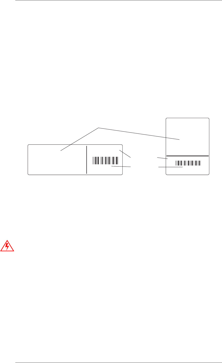
When requesting information, please quote either the manual product code (e.g.
M830P-00-1TA), or the equipment product code and serial number which are printed on
a label on the back of the product (as shown in Figure 1.1).
Figure 1.1 Typical Product Code & Serial Number Labels
If you require information about a particular PCB, please quote the full PCB internal
part number (IPN) which is screen printed onto the top side of the board (refer to the
appropriate PCB Information section in this manual for more details).
1.2 Caution: CMOS Devices
This equipment contains CMOS Devices which are susceptible to damage from static
charges. Care when handling these devices is essential. For correct handling proce-
dures refer to the manufacturers' data books, e.g. Philips data books covering CMOS
devices, or Motorola CMOS data books, Section 5 'Handling', etc.
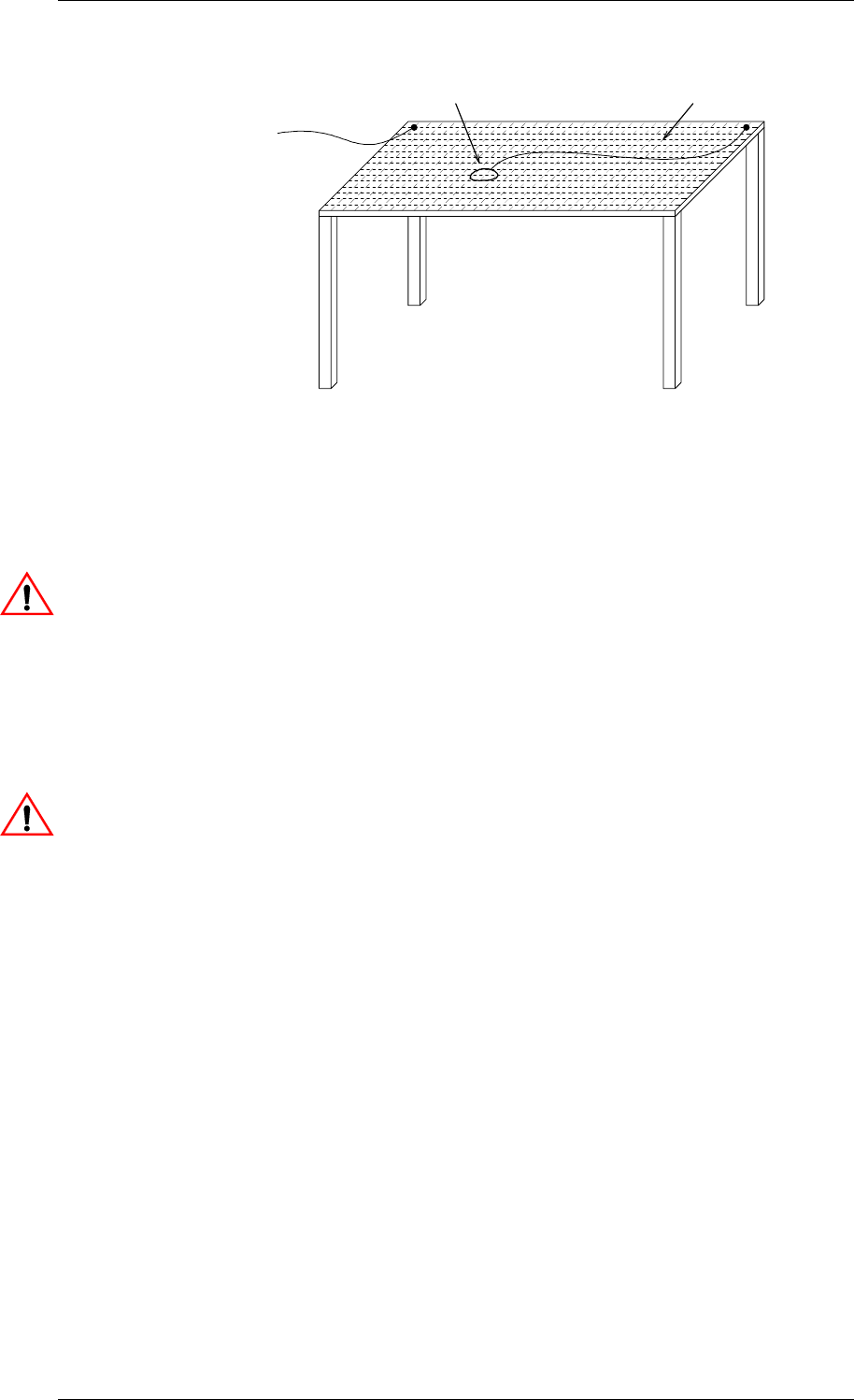
An anti-static bench kit (refer to Figure 1.2) is available from Tait Electronics Ltd under
the following product codes:
• KS0001 - 1 conductive rubber bench mat
- 1 earth lead to connect the mat to ground
•KS0004- 1 wrist strap.
this area used for regional
Type Approval information
product code
serial number
T835-10-0000
Rev 1
900000
Tait Electronics Limited
Made in New Zealand
T838-10-0000
Rev 1
900000
Tait Electronics Limited
Made in New Zealand
A1.2 General M830P-00
01/07/03 Copyright TEL
Figure 1.2 Typical Anti-static Bench Set-up
1.3 Caution: Aerial Load
The equipment has been designed to operate safely under a wide range of aerial loading
conditions. However, we strongly recommend that the transmitter should always be
operated with a suitable load to prevent damage to the transmitter output power stage.
1.4 Caution: Beryllium Oxide & Power Transistors
The RF power transistors in current use all contain some beryllium oxide. This sub-
stance, while perfectly harmless in its normal solid form, can become a severe health
hazard when it has been reduced to dust. For this reason the RF power transistors
should not be broken open, mutilated, filed, machined, or physically damaged in any
way that can produce dust particles.
1.5 USA Installations: RF Exposure Compliance, Control
Guidelines and Operating Instructions
All radio transmitter installations must comply with the FCC environmental rules (refer
to CFR 47 Chapter 1, sub-part I). In addition, the FCC requires the following safety
information to be provided by the radio manufacturer:
To control exposure to yourself and others and ensure compliance with the gen-
eral/uncontrolled and occupational/controlled environment exposure limits
always adhere to the following procedures.
to building earth
(not mains earth)
conductive
wrist strap
conductive rubber
bench mat
M830P-00 General A1.3
Copyright TEL 01/07/03
Guidelines:
• User awareness instructions must accompany this device when transferred to
other users.
• Do not use this device if the operational requirements described herein are not
met.
Instructions:
• Transmit only when people near the antenna are at least the recommended
minimum distance away, as shown in Table 1.1, from a properly installed,
according to installation instructions, externally-mounted antenna.
Note: Table 1.1 lists the recommended minimum distance for bystanders in an
uncontrolled environment from transmitting types of antennas at fre-
quencies in the range 138-174MHz and several different ranges of rated
radio power.
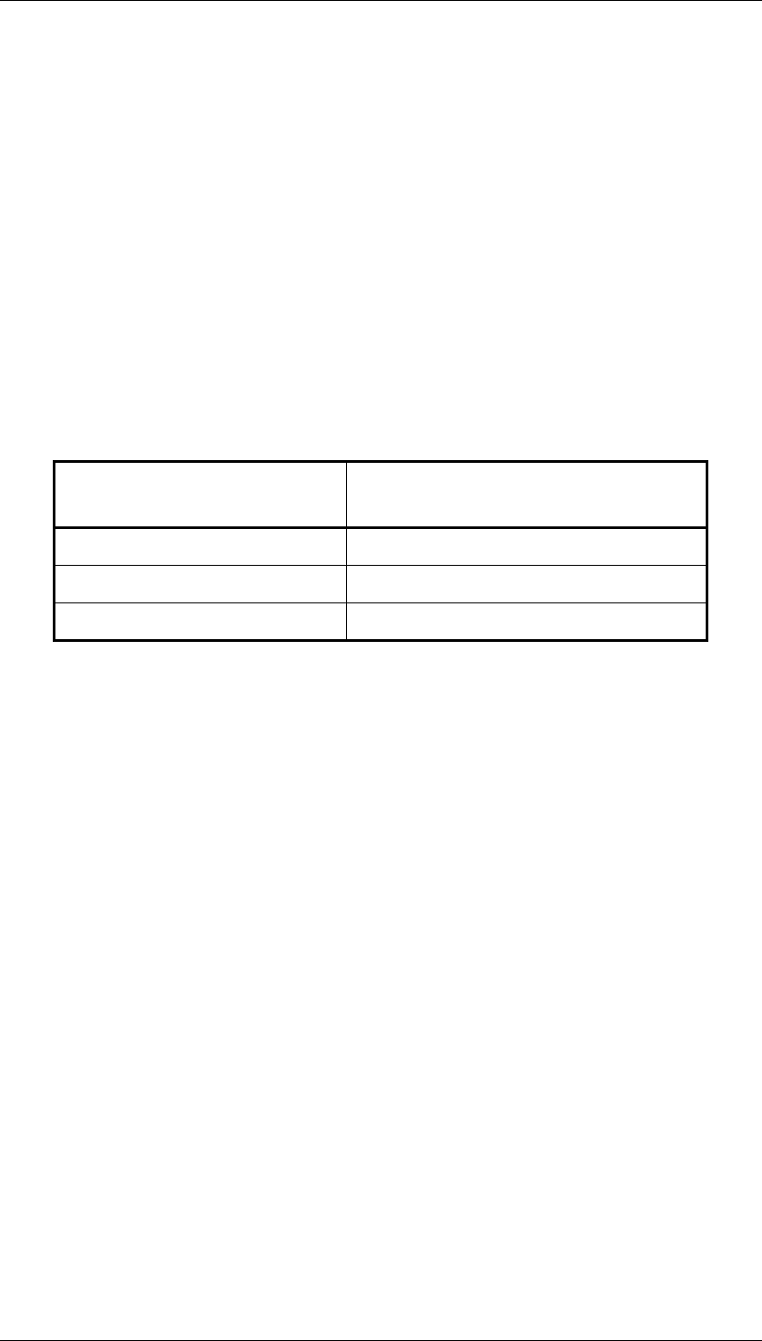
Table 1.1 Rated Power and Recommended Distance
Rated Power of Transmitter Recommended Minimum Distance
from Transmitting Antennaa
a.These distances are calculated based on a 6dBi gain collinear antenna as might be
used in a typical installation. For other powers and antenna types, consult the sup-
plier.
513cm
50 133cm
100 watts 265cm

A1.4 General M830P-00
01/07/03 Copyright TEL