TandD 10080 HAND HELD DATA COLLECTOR User Manual
TandD Corporation HAND HELD DATA COLLECTOR Users Manual
UserManual.wiki
>
TandD
>
10080 User Manual
Users Manual
Navigation menu
Upload a User Manual
Namespaces
Wiki Guide
HTML
PDF
Info
Views
User Manual
Discussion / Help
Navigation
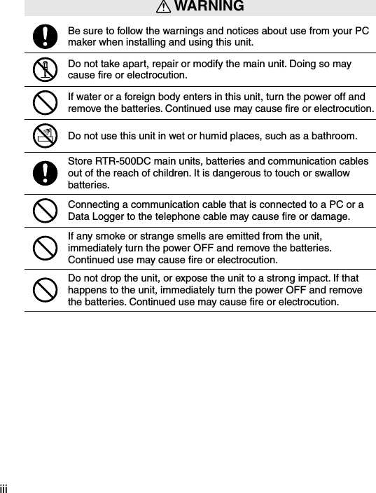
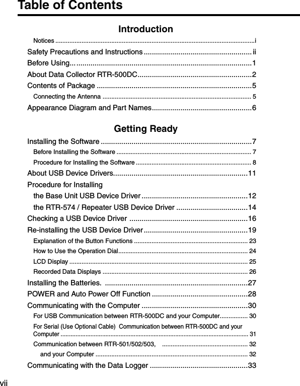
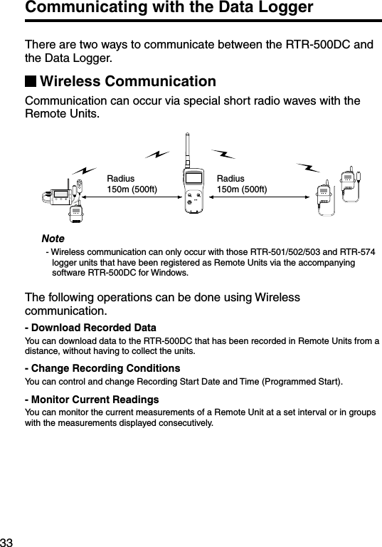
![1Before Using...Important Notes about the Installation Procedure (for using this product with USB communication)Thank you for choosing T&D Products In order to use a USB connection to communicate between this product and a PC, it is necessary to install the application and the USB driver. Before connecting this product to a PC with a USB cable, it is necessary to first install the application and the USB driver.If you use the USB cable to connect the product to a PC before installation, the USB driver may not properly install. If you have connected the product to a PC without first installing the driver, please make sure to press [Cancel] in the [Installation Wizard] window when it pops up the PC screen and then disconnect the USB cable from the product. For more details about the proper installation procedure, see the Software Introductory manual that accompanies [RTR-500DC for Windows ]. Windows Vista[Cancel]ButtonFor other Windows Operating Systems * The screen shot below is from Windows XP. For other Windows OS, there is also a [Cancel] button in the lower right of the screen. (Your screen may differ slightly if you are using a Windows OS other than XP.) [Cancel]Button](https://usermanual.wiki/TandD/10080/User-Guide-1406698-Page-10.png)
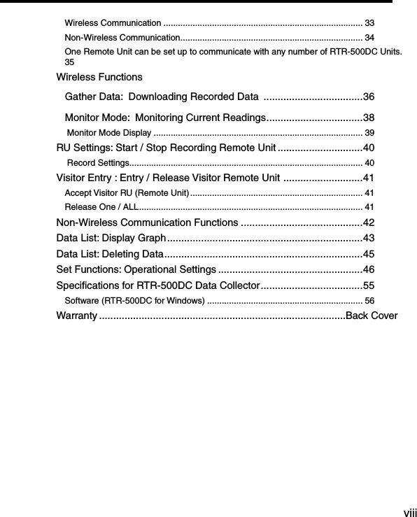
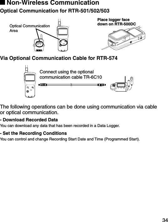
![7Installing the SoftwareMake sure to install the software before connecting the Unit to a PC with the USB cable. If you have connected a Unit to your computer before installing the USB device driver, make sure to click the [Cancel] button in the Wizard window when it pops up on the computer display. Then disconnect the USB cable from the Unit.Before Installing the SoftwareIs Windows working properly? If Windows is not operating properly, the software may not be installed correctly or it may not operate properly.Make sure to check that the OS you are running and “RTR-500DC for Windows”are compatible. Microsoft Windows 7 32/64bit English Microsoft Windows Vista 32bit English Microsoft Windows XP 32bit (SP2 or above) English - For details about the necessary operating environment, see page 51.Quit all other applications If you are running other applications, make sure to quit them before installation. If you have any permanently active software, such as a virus check or scan program in your computer, make sure to also quit it.To install “RTR-500DC for Windows”, it is necessary to have Administrator rights (Computer Administrator) for the computer in which you wish to install it.](https://usermanual.wiki/TandD/10080/User-Guide-1406698-Page-16.png)
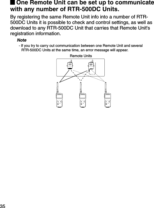
![8Procedure for Installing the SoftwareThis explanation uses displays from Windows XP SP2.- If your OS is Windows Vista or Windows 7, the window layout may be slightly different. However, the message contents and the button operations are the same, so please follow the directions as written below.1. Open Windows.2. Place the supplied software (CD) into the CD-ROM drive. The "Install Program" window will appear soon.* In Windows Vista or Windows 7, if the [Auto Play] window appears, click on "Run Start.exe". If the "Install Program" window does not automatically open, please open it by double clicking on the CD drive icon in [My Computer]. 3. Select "Install RTR-500DC for Windows" and click the [Execute] button to start the installation. 4. The "RTR-500DC for Windows" Setup Wizard window will appear.Click the [Next] Button](https://usermanual.wiki/TandD/10080/User-Guide-1406698-Page-17.png)
![95. The "Software License Agreement" window will appear. Please read all the terms stipulated in the agreement. Check "I accept the terms of the license agreement" if you accept the terms. Click the [Next] button.6. The "Choose Destination Location" window will appear. Click the [Next] button. By clicking the [Change] Button it is possible to change the installation folder. Info for file to be installed 7. The "Ready to Install the Program" window will appear. Click the [Install] Button to begin installation.](https://usermanual.wiki/TandD/10080/User-Guide-1406698-Page-18.png)
![10 Although a warning message such as below may appear, there is no problem, please move on to the next step.Warning MessageFor Windows XPClick the [Continue Anyway] ButtonFor Windows Vista and Windows 7Click the [Install] Button8. After installation has been completed, "RTR-500DC for Windows" will be registered in the Window's [Start] Menu. After having installed the supplied software it is necessary to install the USB Device Driver. - See the following pages for details.](https://usermanual.wiki/TandD/10080/User-Guide-1406698-Page-19.png)
![11About USB Device DriversHave you installed the software?Before connecting a Unit to a PC with a USB cable make sure to install the Software first. For Units using a USB connection, it is necessary to first install the Software, and upon connecting the Unit to the PC with a USB cable it is necessary to install the USB Device Driver. A USB Device Driver enables the PC to recognize the connected device and ensure proper operation. - To ensure a proper connection, make sure that the USB cable is inserted fully.- Login using a User Account with Administrator (Computer Administrator) rights.Users of Windows XP must carry out the Installation Procedure.Upon connecting a Unit to your PC, the [New Hardware Detection Wizard] will automatically open. Please carry out the procedures on the following pages to install the USB Device Drivers for the Base Unit (RTR-500DC), Remote Units (RTR-574), and if necessary, Repeaters (RTR-500). - In XP, if the Wizard window does not automatically open, installation may have not been fully completed or failed. Please check the USB device driver. Users of Windows Vista or Windows 7 do not have to carry out this installation. By installing the supplied software, the USB Device Drivers for the Base Unit, Remote Units and Repeaters will also be automatically installed. It is not necessary to carry out any extra steps to install the USB Device Drivers. - See page from 28 of this Manual for about how to confirm that the USB Device Driver has been properly installed.](https://usermanual.wiki/TandD/10080/User-Guide-1406698-Page-20.png)
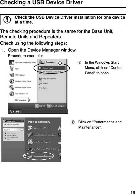
![12Procedure for Installing the Base Unit USB Device DriverCarry out all USB Device Driver installations for only one Unit at a time.Users of Windows XP should carry out the following procedure to install the USB Device Driver.1. By connecting a Base Unit to your computer, the [New Hardware Detection Wizard] will automatically open.- The “Wizard” window will only appear upon the first connection. Check "No, not this time". Click the [Next] Button. Check "Install the software automatically (Recom-mended)". Click the [Next] Button.](https://usermanual.wiki/TandD/10080/User-Guide-1406698-Page-21.png)
![132. The installation process will begin. If a warning message window appears, click the [Continue Anyway] button, and continue with the installation.3. Once the completion message appears, installation has finished. Click the [Finish] Button.](https://usermanual.wiki/TandD/10080/User-Guide-1406698-Page-22.png)
![14Procedure for Installing the RTR-574 / Repeater USB Device DriverCarry out all USB Device Driver installations for only one Unit at a time.Users of Windows XP should carry out the following procedure to install the USB Device Driver.1. By connecting a Remote Unit (RTR-574) or a Repeater to your computer, the [New Hardware Detection Wizard] will automatically open.The “Wizard” window will only appear upon the first connection. Check "No, not this time". Click the [Next] Button. Check "Install the software automatically (Recom-mended)". Click the [Next] Button.2. The installation process will begin.](https://usermanual.wiki/TandD/10080/User-Guide-1406698-Page-23.png)
![15If a warning message window appears, click the [Continue Anyway] button, and continue with the installation.3. Once the completion message appears, installation has finished. Click the [Finish] Button. - See page from 16 of this Manual for about how to confirm that the USB Device Driver has been properly installed.](https://usermanual.wiki/TandD/10080/User-Guide-1406698-Page-24.png)
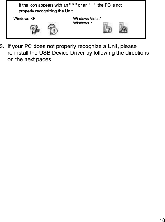
![17 Click on "System". In the System Properties Window, click on the [Hardware] tab. Click the [Device Manager] Button.2. Connect the target Unit to the computer with a USB cable and look at the icon displayed in the Device Manager window in order to check whether or not the USB Device Driver has been properly installed.If failed (example)If successful (example)](https://usermanual.wiki/TandD/10080/User-Guide-1406698-Page-26.png)
![19Re-installing the USB Device Driver1. Right click on the icon.2. From the pop-up menu click on "Properties" .3. When the following window appears, click on the [Reinstall Driver] button to display the Wizard window.[General] Tab Window[Reinstall Driver] Button](https://usermanual.wiki/TandD/10080/User-Guide-1406698-Page-28.png)
![204. If you are using Windows XP, please follow the directions below and move on to step 6. Check the "Install from a list or specific location (Advanced)". Click the [Next] Button. Check the "Include this location in the search:". Click the [Browse] Button.5. If you are using Windows Vista or Windows 7, please follow the directions below. Click the "Browse my computer for driver software".](https://usermanual.wiki/TandD/10080/User-Guide-1406698-Page-29.png)
![21 Click the [Browse] Button.6. Specify the location of the Driver. Click the plus (+) sign next to the folder into which the software was installed and specify "Device Driver" as the driver location. Click the [OK] button to return to the Wizard window.7. In the Wizard window, check to make sure that the Driver is specified correctly. Then click the [Next] button.For Windows XP For WIndows 7 and Windows VistaLocation Example:C:\Program Files\RTR-500W for Windows\Driver RTR-500](https://usermanual.wiki/TandD/10080/User-Guide-1406698-Page-30.png)
![228. The installation process will begin. Please note that the following warning messages may appear during installation. However, this will cause no problems with USB device driver installation. Please move on to the next step. Warning MessageFor Windows XPClick the [Continue Anyway] Button Click the [Install] ButtonFor Windows Vista and Windows 79. After installation has been completed, please click the [Finish] or [Close] button. 10. Check to make sure that the USB Device Driver has been properly installed. See page from 16 of this Manual for details.](https://usermanual.wiki/TandD/10080/User-Guide-1406698-Page-31.png)
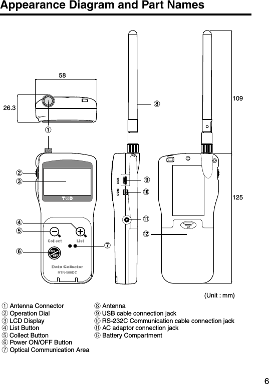
![23Explanation of the Button Functions- When downloading via wireless communication the [Select Group] display will appear.- Allows you to swift-scroll across data when viewing a graph or an event list.- The downloaded data list will be displayed.- Allows you to swiftly make changes to the upper and lower limit value settings.- Switch Power ON/OFF.](https://usermanual.wiki/TandD/10080/User-Guide-1406698-Page-32.png)
![24How to Use the Operation DialPress inMove the dial upMove the dial down[Moving the dial up and down]- By moving the dial up or down the arrow will move to allow you to choose the desired item. The selected part will be displayed in an easy-to-see inversed shade.- When setting a numerical value, by moving the dial up the value will become larger and by moving the dial down the value will become smaller.[Pressing in on the dial]- Switching the Power On.- You cannot switch the power OFF with the operation dial. Press in on the <POWER> button.- By pressing in on the dial, you can make a desired menu selection or complete and activate a setting.- Keeping the dial pressed in (1.5 seconds) will activate different functions depending on the display being viewed.If you keep it pressed in while viewing the graph display, you can change the display channel.](https://usermanual.wiki/TandD/10080/User-Guide-1406698-Page-33.png)
![25LCD Display①The item marked with an arrow [ ] denotes it has been selected. If you move the operation dial up and down, the arrow will move accordingly and by pressing in the dial the item selected will be activated.②Items marked with [ ] indicate menus for Wireless Communication.③Items marked with [ ] indicate menus for Optical / Wired Communication.④ A [ ] [ ] indicates that there are more menu items above [ ] or below the [ ] to view.⑤ When battery life goes low, a battery life warning mark [ ] will be displayed to inform you it is time to replace the battery. If there is a [BACK] is displayed, adjust the arrow to [BACK] and press it to complete the setting and take you back to the menu display.①③④⑤②](https://usermanual.wiki/TandD/10080/User-Guide-1406698-Page-34.png)
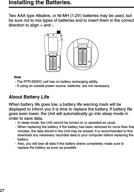
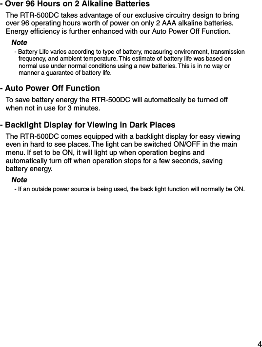
![28POWER and Auto Power Off FunctionSwitch the power ON by pressing the <POWER> button or the Operation Dial. To switch the power OFF, press the <POWER> button. You cannot switch the power OFF with the Operation Dial.Press the Operation Dialor<ON/OFF>Button[Auto Power Off Function]If the main unit is not in use for 3 minutes, the power will be automatically switched off in order to save battery power. If you wish to continue to use, switch the power on again.Note- If using the monitoring function, the Auto Power Off function will not go into effect.- AUTO power OFF is not done while being connecting USB or AC adaptor.](https://usermanual.wiki/TandD/10080/User-Guide-1406698-Page-37.png)
![29Setting the Date and TimeFollow the procedure below to make clock settings for the Unit. 1. In the Main Menu, go to [Set Functions] and select [Set Clock].2. Set the desired values.(1) Moving the Operation Dial up and down will change the selection item of the display in the order of month, day, year, hour, and minute. By pressing the dial, the value for that item will flash.(2) Change the value by moving the dial up and down. Press the dial again to set the selected value and move to the next settings item.3. After having completed the clock settings, move the arrow to [Back] and press the dial to return to the Menu Window.[Time Zone]By setting the region in which the Unit will be used the time difference will be automatically set. Daylight Savings Time settings must be set manually. - Please make sure that the date and time settings in the Unit is correct, if it is not, the recording start time and recording time of downloaded data will be incorrect.- Clock settings for the Unit can also be made from your computer by using the software supplied with the Unit. For more details, see the [Help] Menu in the supplied software or the User’s Manual that accompanies it.](https://usermanual.wiki/TandD/10080/User-Guide-1406698-Page-38.png)
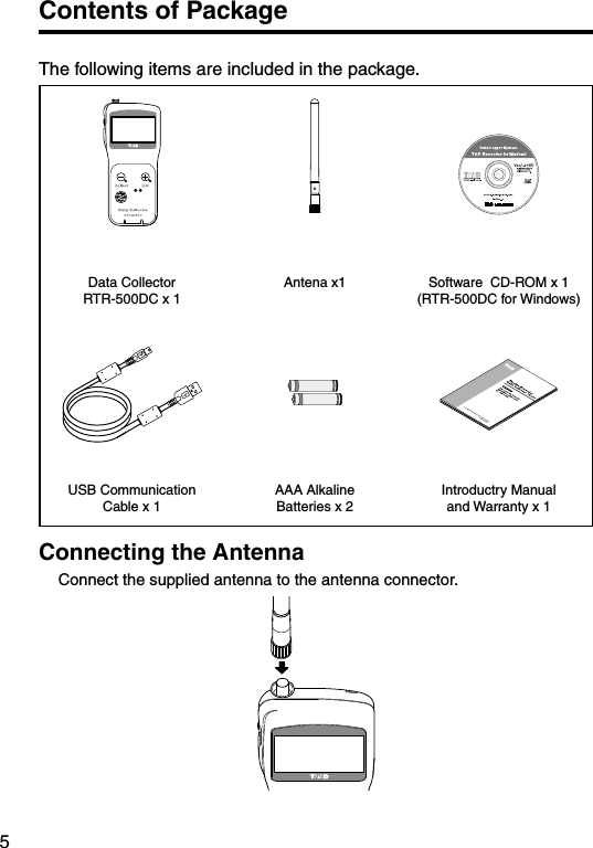
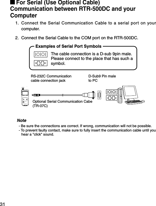
![30Communicating with the ComputerFor direct communication with your computer to download or make setting changes, etc... please use a USB communication cable (provided) or the serial cable (optional). You can transfer the registration contents from one RTR-500DC to another via the attached software. For details see the [Help Menu] in “RTR-500DC for Windows” or the Introductory manual that accompanies it.Note- Communication with a computer cannot be carried out while a wireles communication session is occuringFor USBCommunication between RTR-500DC and your ComputerYou will need to install the USB Device Driver in order to use the device with a USB cable and Windows. After installing, your computer will be able to detect and recognize an RTR-500DC device that has been connected with a USB cable.USB mini-BTo the RTR-500DCUSB ATo the computerIncludedUSB Cable (US-15C)](https://usermanual.wiki/TandD/10080/User-Guide-1406698-Page-39.png)
![32Communication between RTR-501/502/503, and your Computer1. Connect the communication cable.Connect the RTR-500DC Unit to your computer with the provided communication cable. (USB or RS-232C)Place the Data Logger on the RTR-500DC.2. In order to carry out wireless communication, register Groups and Remote Units.Place the unit face down on the RTR-500DC.Communication Cable (to computer)Note- If light enters during communication, an error will occur. Please make sure to place the unit within the ridges for an exact fit.- For details about how to register, see the [Help Menu] in the provided software [RTR-500DC for Windows ] or the accompanying Introductory manual.](https://usermanual.wiki/TandD/10080/User-Guide-1406698-Page-41.png)
![36Wireless Functions: Gather Data Downloading Recorded Data 1. In the Main Menu, open [ WL Gather Data] .2. Choose a Group.3. Select the Remote Unit you wish to download the data from.4. Press on [Execute].①② ① Rpt Route : Repeater RouteChoose from No Rpt (No Repeter) or Obey Reg (Obey Register)②Before :Period of DataYou can set the period (how many hours or days before now) from which you wish to download data.- You can select from 1 to 47 hours (in 1 hour units) / 2 to 300 days (Less than 300 days in units of 1 day, or ALL DATA.- If you specify the period of data that is earlier than the period of the data saved in the remote unit, all saved data will be downloaded. 5. Press on [Execute].](https://usermanual.wiki/TandD/10080/User-Guide-1406698-Page-45.png)
![37If Downloading Recorded Data FailsIf there is not enough memory remaining, the message [Memory Over] will appear and downloading will stop. Please save recorded data from the TR-57DCi to your PC and delete unnecessary data from the TR-57DCi to make space for downloading new data from the Data Logger.](https://usermanual.wiki/TandD/10080/User-Guide-1406698-Page-46.png)
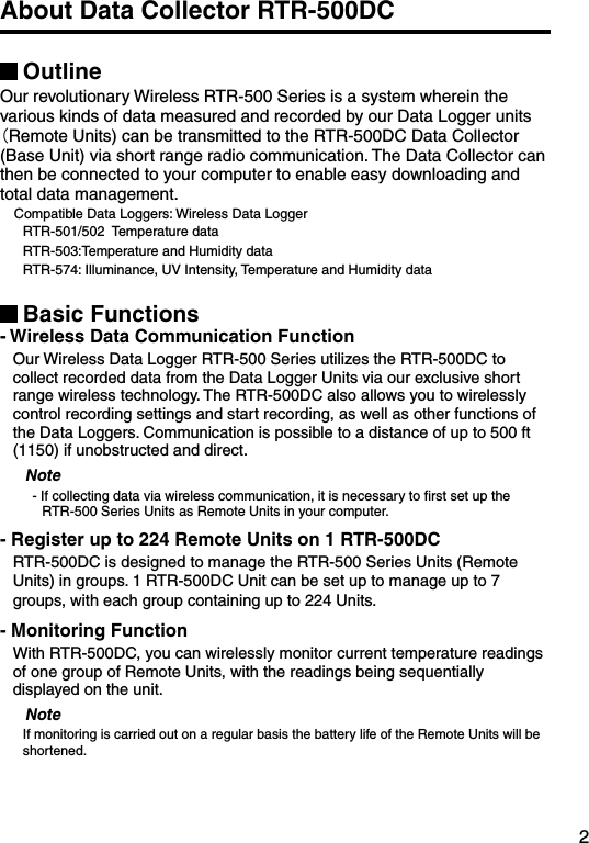
![38Wireless Functions: Monitor Mode Monitoring Current ReadingsThe RTR-500DC can be set to patrol and monitor Remote Units groups and display in order the current readings for view.1. In the Main Menu, open [ WL RU Settings] and then Select [Monitor Mode] .2. Select the monitoring range and Set the monitoring interval.3. Press Operation Daial.①②③④①All GroupsRemote Units in all groups registered to the RTR-500DC will be contacted via wireless communication. ②Specify GroupAll Remote Units in the selected groups will be contacted via wireless communication.- If you wish to monitor using the [All Groups] range, it is possible to monitor only 120 Remote Units. Therefore, when making changes to the [Set Number of Possible Registrations] make sure to register no more than 120 Remote Units to the Group or use the [Specify Group] range as oulined below. ③Specify a Remote UnitAll Remote Units in the selected groups will be contacted via wireless communication.④Interval The monitoring interval is the amount of time between the starting of wireless communication to gather current Remote Unit readings. Selections can be made from 10 sec to 60 minutes (in 1 minute units).- The amount of communication time depends on the number of registered groups and remote units. Please note that if the monitoring interval is set for less time than communication takes to complete a round of monitoring, the system will automatically extend the interval to allow for the necessary amount of communication time.](https://usermanual.wiki/TandD/10080/User-Guide-1406698-Page-47.png)
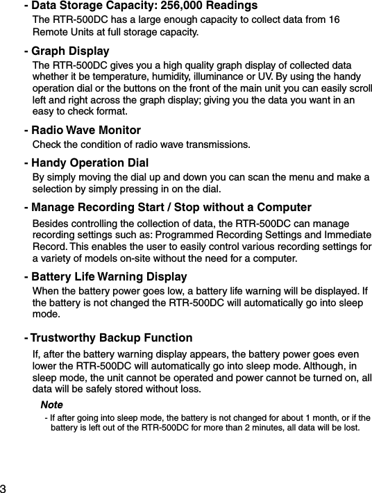
![39Monitor Mode DisplayCurrent measurement readings for those units with which communication is possible will be displayed consecutively every 2 seconds. For those units with which communication is impossible the measurement will be displayed as [----].⑥⑦⑧⑨⑪ ⑩③②① The number of the cordless handsets displaying a cross axle②Recording Status, Recordeing Mode Icon, Recording Interval (S: Seconds , M: Minute)③Battery Status of Remote UnitQuantity of current record readings⑤Value of current readings⑥ Upper / Lower Limit⑦ Warning result⑧Remote Unit Name Group Name⑩The strength of the wireless Radio wave at the time of the latest communication with the monitor⑪ When there is it via Repeater, it is displayedFor RTR-574 For RTR-501/502/503⑤④](https://usermanual.wiki/TandD/10080/User-Guide-1406698-Page-48.png)
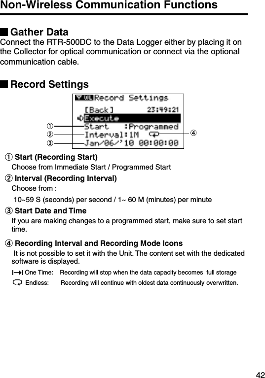
![40Wireless Functions: RU Settings Start / Stop Recording Remote Unit1. In the Main Menu, open [ WL RU Settings] and then Select [Start Recording] or [Stop Recording] .①②2. Choose a Group in select menu.3. Select a Group in which Remote Units are registered.4. Press on [Execute].Record Settings①②③④①Start (Recording Start) Choose from Immediate Start / Programmed Start②Interval (Recording Interval) It is not possible to set it with the Unit. The content set with the dedicated software is displayed. ③Start Date and TimeIf you are making changes to a programmed start, make sure to set start time.④Recording Interval and Recording Mode IconsIt is not possible to set it with the Unit. The content set with the dedicated software is displayed. One Time: Recording will stop when the data capacity becomes full storageEndless: Recording will continue with oldest data continuously overwritten.](https://usermanual.wiki/TandD/10080/User-Guide-1406698-Page-49.png)
![41Wireless Functions: Visitor Entry Entry / Release Visitor Remote Unit Accept Visitor RU (Remote Unit)1. In the Main Menu, open [ WL Visitor Entry] and then Select [Accept Visitor RU] .2. Press on Operation Dial.CompletedVistor Entry Completed, shows Serial No, of Remote Unit. and Unit Name on this Units has given automaticaly DuplicationVistor Entry Completed, shows Serial No, of Remote Unit. and Unit Name on this Units has given automaticaly IncompatibleThe unit accept RTR-500 series Data Loggers only.Release One / ALLSelect the Visitor Remote Unit you wish to Release from [Release One] or [Release All] and Press on [Execute].](https://usermanual.wiki/TandD/10080/User-Guide-1406698-Page-50.png)
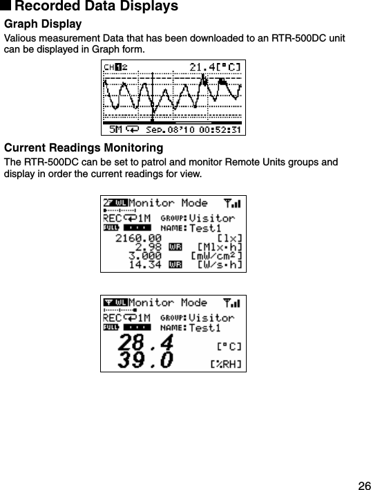
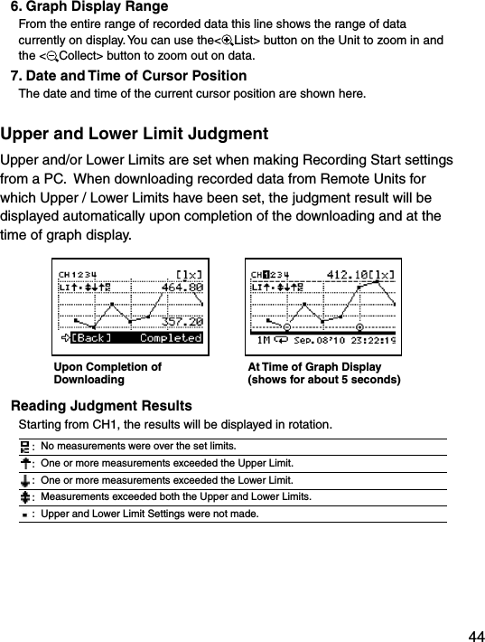
![43Data List: Display GraphIn this display you can view in graph form the recorded data col-lected by the Unit. A graph is displayed for each channel of data and can be scrolled left and right with the Operation Dial or by the buttons on the Unit.1.2.3. 7.4.6.5.1. Displayed ChannelIf there are multiple channels of recorded data, you can change the channel on display by holding in the Operation Dial (for about one second). 2. CursorBy moving the Operation Dial, you can scroll the cursor left and right to view the recording date and time and measurement for that point where the cursor is positioned. 3. Recording Interval and ModeThe “Recording Interval” and “Recording Mode” for the displayed data are shown here.S: Seconds, M: Minutes, : One Time, : Endless4. Measurement at Cursor Position The corresponding measurement value is displayed for the date and time where the cursor is positioned.[°C/°F]: Temperature[%RH]: Humidity, [hPa]: Barometric Pressure[lx]: Illuminance[mW/cm2]: UV Light5. Upper and Lower Limit If Upper and/or Lower Limits have been set in the Data Loggers these limits will be shown using dotted lines.](https://usermanual.wiki/TandD/10080/User-Guide-1406698-Page-52.png)
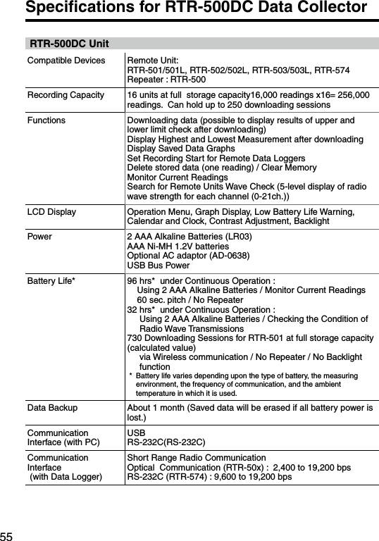
![45Data List: Deleting DataAll downloaded data is temporarily saved in the Unit. It is possible to select it for deletion.Deleting Selected Data1. In the Main Menu, open [Data List]. Select the data you wish to delete and press the Operation Dial.Main Menu Select data2. Move the arrow to [Select Delete] and press the Operation Dial.3. A confirmation screen will appear. Select [Execute] to delete the selected data or [Back] not to delete it, and press the Operation Dial.4. Upon completion of deletion, it automatically returns to the data selection display.- When you want to delete all data, please execute [Memory Clear] in [Set Functions] .](https://usermanual.wiki/TandD/10080/User-Guide-1406698-Page-54.png)
![46Set Functions: Operational SettingsBy changing the Unit of Temperature, the Recorded Data display in the Unit and the LCD display on the target Remote Unit(s) for which recording was started from the Unit will be also be changed to reflect the new setting. ■Set Temp Unit : Changing Unit of Temperature1. In the Main Menu, open [Set Functions] and [Set Temp Unit].Current SettingSelect2. Move the arrow to [°C] or [°F] and press the Operation Dial. Default value: [°F] 3. Move the arrow to and click on [Back] to return to the Main Menu.■Set Backlight : Adjusting the Backlight1. In the Main Menu, open [Set Functions] and [Set Backlight].2. Move the Operation Dial up to make the light brighter and down to make it darker. Default value: 80 (OFF, 1 to 100)3. Press the Operation Dial to return to the Main Menu.The backlight maintains lighting while connecting the AC adaptor.](https://usermanual.wiki/TandD/10080/User-Guide-1406698-Page-55.png)
![47■Set Contrast : Adjusting Contrast1. In the Main Menu, open [Set Functions] and [Set Contrast].2. Move the Operation Dial up to make the display darker and down to make it lighter. Default value: 65 (0 to 100)3. Press the Operation Dial to return to the Main Menu.■Check Memory: Checking Storage Capacity of the Unit1. In the Main Menu, open [Set Functions] and [Check Memory].2. Press the Operation Dial to return to the Main Menu.](https://usermanual.wiki/TandD/10080/User-Guide-1406698-Page-56.png)
![48■Clear Memory: The memory of the Unit is adjusted to Zero.1. In the Main Menu, open [Set Functions] and [Clear Memory].2. Press on the Execute.■Set Clock: Making Clock Settings1. In the Main Menu, open [Set Functions] and [Set Clock].2. Select the item you wish to change and press the Operation Dial.3. Move the Operation Dial up and down to adjust clock.4. Move the arrow to and click [Back] to return to the Main Menu.](https://usermanual.wiki/TandD/10080/User-Guide-1406698-Page-57.png)
![49■Beep: Muting the Operation Beep1. In the Main Menu, open [Set Functions] and [Beep].Current SettingSelect2. Move the arrow to either [ON] or [OFF] and press the Operation Dial to confirm.3. Move the arrow to [Back] and press the dial to return to the Main Menu.■Battery Voltage: Checking Battery Voltage1. In the Main Menu, open [Set Functions] and [Battery Voltage].2. Press the Operation Dial to return to the Main Menu.Battery Voltage:When battery power depletes to about 2.30V, the battery life warning mark will appear.](https://usermanual.wiki/TandD/10080/User-Guide-1406698-Page-58.png)
![50■Radio Wave Monitor: Checking the Condition of Radio Wave TransmissionsDepending on the location of the logger, at special frequencies there may be some instances in which, due to radio wave interference or other causes, communication capability does not meet expected standards. To help avoid interference and reduce the chances of poor transmission, we suggest that before registering a Remote Unit you check the condition of radio wave transmissions and when creating a new Group assign the units to an empty frequency channel. The radio wave strength is displayed in a scale from 1 to 5, with the higher the number the stronger the radio waves are. Longitudinal axis:Radio Wave Strength(1 to 5)Horizontal axis:Frequency Channel 1. From the Main Menu, select [SET FUNCTIONS].2. From the [SET FUNCTIONS] menu, select Radio Wave Monitor. (Wave Check)3. Close the Radio Wave Monitor by pressing in on the operation dial. (Returns to the [SET FUNCTIONS] Menu)Note- While using the Radio Wave Monitoring Function, the Auto Power Off Function will be disabled.](https://usermanual.wiki/TandD/10080/User-Guide-1406698-Page-59.png)
![51Menu ListGATHER DATA[Back]Group List [Back]RU / VRU List [Back]ExecuteRepeater Rout :No Rpt / Obey Reg Specify Period of Data to be DownloadedStart Downloading DataCanceled ** It is possible to cancel by pushing the operation dial while Downloading.Monitor Mode[Back]Group List[Back]Group List[Back]All GroupsSpecify a GroupSpecify a Remote UnitInterval [Back]RU / VRU ListStart SerchingCanceled ** It is possible to cancel by pushing the operation dial while Serching.](https://usermanual.wiki/TandD/10080/User-Guide-1406698-Page-60.png)
![52RU Settings[Back]Group List[Back]Group List[Back]Start RecordingStop Recording[Back]RU / VRU List[Back]RU / VRU List[Back] Time ExecuteStart:Programmed / immImmediateInterval *1Recording Mode*1‘YY/MM/DD XX:XX:XX *2[Back] Execute[Back]Confirmatin Display*1 Only the confirmation.*2 Sets it for Programmed Start.](https://usermanual.wiki/TandD/10080/User-Guide-1406698-Page-61.png)
![53Visitor Entry[Back]Join VRU, Push Dial[Back]Vistor List[Back]Accept Visitor RURelease OneRelease All[Back] Serial No *Unit Name *[Back] Execute[Back] Execute* Only the confirmation. Gather DataSpecify the period of data to be downloaded.Upon completion of the download, a graph will appear. Recording Settings[Back]Execute Send Recording Settings to Remote unit.StartInterval*REC Mode*REC Mode*YY/MM/DD XX:XX:XX *2*1 Only the confirmation.*2 Sets it for Programmed Start.](https://usermanual.wiki/TandD/10080/User-Guide-1406698-Page-62.png)
![54Data List[Back]Data List [Back]Display Graph (Press Operation Dial to display Graph)[Back]ContinueSelect Delete [Back]ExecuteSet Functions[Back]Set Temp Unit Back°C°FSet Backlight BackOFF, 1 to 100Set Contrast Back0 to 100Check Memory BackDisplay Memory Usage (%)Clear Memory BackExecuteSet Clock BackSettingsBeep BackONOFFBattery Voltage BackDisplay Battery Voltage (V)Radio Wave Monitor Display](https://usermanual.wiki/TandD/10080/User-Guide-1406698-Page-63.png)
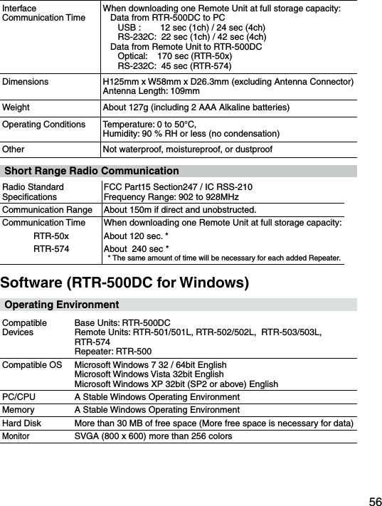
![57Optional AccessoriesRS-232C Communication Cable[unit: mm]TR-07CRS-232C Communication CableCable Length: 1.0m (40 in)Connector Type:Specialized Connector D-sub9pin 1500TR-6C10Cable Length: 1.0m (40 in)USB Communication Cable[unit: mm]US-15CCable Length: about 1.5m (60in)1500AC AdaptorAD-0638Input: AC100-240VOutput: DC6V 500mAFrequency: 50/60HzCable length: 1.85m (74in)Plug Figuration: A To RTR-500DCTo RTR-500DCTo PCTo PCTo RTR-574To RTR-500DC1000](https://usermanual.wiki/TandD/10080/User-Guide-1406698-Page-66.png)