TandD 10080 HAND HELD DATA COLLECTOR User Manual
TandD Corporation HAND HELD DATA COLLECTOR Users Manual
TandD >
Users Manual
© Copyright T&D Corporation. All rights reserved.
2010.11
RTR-500DC
Introductory Manual
Thank you for purchasing our product. This
manual explains in brief how to get an RTR-
500DC unit ready for use and how to install the
software.
Details about how to use the software "RTR-
500DC for Windows" and its functions can be
found in the software "Operation Guide (Help)".
i
Notices
Carefully read this manual so that you can properly use this product.
T&D Corporation accepts no responsibility for any malfunction of and/or
trouble with this product or with your computer that is caused by the
improper handling of this product and will deem such trouble or malfunction
as falling outside the conditions for free repair of the attached warranty.
- All rights of this Introductory Manual belong to T&D Corporation. It is
prohibited to use, duplicate and/or arrange a part or whole of this
Introductory Manual without the permission of T&D Corporation.
- Microsoft ® and Windows ® are registered trademarks of Microsoft
Corporation USA and are binding in the USA and all other countries.
- Company names and product names are trademarks or registered
trademarks of each company.
- Specifications, design and other contents are subject to change without
notice.
- On screen messages in this manual may vary slightly from the actual
messages.
- Please notify the shop where you purchased this product or T&D
Corporation of any mistakes, errors or unclear explanations in this manual.
T&D Corporation accepts no responsibility for any damage or loss of
income caused by the use of our product.
- This product has been designed for private or industrial use only. It is not
for use in situations where strict safety precautions are necessary such as
in connection with medical equipment, whether directly or indirectly.
- We are not responsible for any malfunction or trouble caused by the use of
our product or by any problem caused by the use of measurement results
of this Unit. Please be fully aware of this before using our product.
- Some of our products, which come under the category of strategic goods
in foreign trade law, need the permission of the Japanese government to
be exported outside of Japan.
- The Manual itself can be downloaded from our Website:
http://www.tandd.com/
ii
Safety Precautions and Instructions
The following items should be strictly obeyed for the safe
usage of this Unit, and for protecting yourself and other
people from bodily harm and/or damage to property.
Before using this product, please read the following carefully
and fully understand the contents.
Explanation of Symbols
Explanation of Warning Symbols
DANGER
These entries are actions that absolutely under
no circumstance should be taken. The taking of
such an action may cause serious personal
physical damage or death.
CAUTION These entries are actions that if taken may lead
to physical injury or damage to persons or things.
Explanation of Picture Symbols
Denotes an important warning or caution.
Denotes a forbidden action.
Denotes an action that must be taken.
iii
WARNING
Be sure to follow the warnings and notices about use from your PC
maker when installing and using this unit.
Do not take apart, repair or modify the main unit. Doing so may
cause fire or electrocution.
If water or a foreign body enters in this unit, turn the power off and
remove the batteries. Continued use may cause fire or electrocution.
Do not use this unit in wet or humid places, such as a bathroom.
Store RTR-500DC main units, batteries and communication cables
out of the reach of children. It is dangerous to touch or swallow
batteries.
Connecting a communication cable that is connected to a PC or a
Data Logger to the telephone cable may cause fire or damage.
If any smoke or strange smells are emitted from the unit,
immediately turn the power OFF and remove the batteries.
Continued use may cause fire or electrocution.
Do not drop the unit, or expose the unit to a strong impact. If that
happens to the unit, immediately turn the power OFF and remove
the batteries. Continued use may cause fire or electrocution.
iv
CAUTION
This unit is not water-resistant. If the unit gets dirty, wipe it with a
clean cloth and a mild detergent.
Do not put your fingers or foreign matter into the communication
port.
Battery life depends on the kind of the batteries, measurement
environment, communication frequency, ambient temperature, and
battery quality.
Do not use batteries other than specified. Doing so may cause fire
or damage.
Do not use an AC adaptor other than specified. Doing so may lead
to fire or damage.
Battery terminals may provide insufficient contact due to age or
vibration. This may lead to data loss.
If the unit will not be used for period of time, for safety reasons
please remove the battery. If left in the unit, it may leak and lead to
malfunctioning.
Condensation may occur if the unit is moved from one environment
to another where the difference in temperature is great. Use the unit
in an environment where the ambient temperature is from 0 to 50
C (32 to 144 F) and the humidity is 90%RH (no condensation) or
less.
Do not expose the unit to harmful gases or chemicals. It may cause
corrosion and/or other danger to the unit and to people handling the
unit.
To prevent damage to the unit from static electricity, remove static
electricity from your body by touching metal around you (door knob,
window frame) before touching the unit.
Static electricity may cause not only damage to the unit, but may
cause breaks in or a loss of data.
v
CAUTION
Do not use the unit in places such as listed below. It may cause
electrocution, fire or have adverse effects on the unit or your PC.
- In places exposed to direct sun light.
The inside temperature of the unit will rise and may cause fire,
damage or deformation.
- In areas exposed to strong magnetic fields.
It may cause damage.
- In places exposed to water leakage.
It may cause damage or electrocution.
- In areas exposed to static electricity.
It may cause damage.
- In areas exposed to vibration.
It may cause an injury, damage, and/or insufficient contact.
- In places which are not flat.
It may lead to the unit being dropped or falling and cause injury or
damage.
- In places exposed to fire or heat.
It may cause damage or a change in shape.
- In places exposed to excessive smoke, dirt and dust.
It may cause damage.

vi
Wireless Regulations
Radio, EMC and Safety Regulations
This device complies with part 15 of the Federal Communications
Commission (FCC) rules and with RSS-210 of the Industry Canada
(IC). Operation is subject to the following conditions:
(1) This device may not cause harmful interference, and
(2) This device must accept any interference received, including
interference that may cause undesired operation
Changes or Modifications not expressly approved by the manufacturer for compliance
could void the user’s authority to operate the equipment.
Note: This equipment has been tested and found to comply with the limits for a Class
B Digital Device, pursuant to Part 15 of the FCC Rules. These limits are designed
to provide reasonable protection against harmful interference in a residential
installation. This equipment generates, uses and can radiate radio frequency energy
and, if not installed and used in accordance with the instructions, may cause harmful
interference to Special Short Range Wireless Communication.
However, there is no guarantee that interference will not occur in a particular
installation. If this equipment does cause harmful interference to radio or television
reception, which can be determined by turning the equipment off and on, the user
is encouraged to try to correct the interference by one or more of the following
measures:
- Reorient or relocate the receiving antenna.
- Increase the separation between the equipment and receiver.
- Connect the equipment into an outlet on a circuit different from that to which
the receiver is connected.
- Consult the dealer or an experienced radio/TV technician for help.
FCC RF Radiation Exposure Statement:
This equipment complies with FCC RF radiation exposure limits set forth for an
uncontrolled environment. This equipment must be installed and operated with a
minimum distance of 30cm between the radiator and your body.
This device has been designed to operate with the supplied antenna only. Use of any other
antenna is strictly prohibited. The supplied antenna has a maximum gain of 0dBi, and has
an impedance of 50 ohms.
Important Notice
We cannot sell these products to distributors or consumers in countries other than
where the wireless Units have been approved for use. If these wireless products are
used outside of the designated areas of the Americas where the devices have been
granted approval, T&D Corporation shall in no manner whatsoever take responsibility
for the usage of these products, nor be liable in any manner for legal consequences
stemming from the usage of these wireless products in unapproved areas.

vii
Table of Contents
Introduction
Notices ..................................................................................................................i
Safety Precautions and Instructions ..................................................... ii
Before Using... ......................................................................................1
About Data Collector RTR-500DC ........................................................2
Contents of Package ............................................................................5
Connecting the Antenna ..................................................................................... 5
Appearance Diagram and Part Names .................................................6
Getting Ready
Installing the Software ..........................................................................7
Before Installing the Software ............................................................................. 7
Procedure for Installing the Software .................................................................. 8
About USB Device Drivers..................................................................11
Procedure for Installing
the Base Unit USB Device Driver ....................................................12
the RTR-574 / Repeater USB Device Driver ...................................14
Checking a USB Device Driver ..........................................................16
Re-installing the USB Device Driver ...................................................19
Explanation of the Button Functions ................................................................. 23
How to Use the Operation Dial .......................................................................... 24
LCD Display ...................................................................................................... 25
Recorded Data Displays ................................................................................... 26
Installing the Batteries. ......................................................................27
POWER and Auto Power Off Function ...............................................28
Communicating with the Computer ....................................................30
For USB Communication between RTR-500DC and your Computer ................ 30
For Serial (Use Optional Cable)
Communication between RTR-500DC and your
Computer ................................................................................................................. 31
Communication between RTR-501/502/503, ................................................. 32
and your Computer ....................................................................................... 32
Communicating with the Data Logger ................................................33

viii
Table of Contents
Wireless Communication .................................................................................. 33
Non-Wireless Communication ........................................................................... 34
One Remote Unit can be set up to communicate with any number of RTR-500DC Units.
35
Wireless Functions
Gather Data: Downloading Recorded Data ...................................36
Monitor Mode: Monitoring Current Readings ..................................38
Monitor Mode Display ...................................................................................... 39
RU Settings: Start / Stop Recording Remote Unit ..............................40
Record Settings ................................................................................................ 40
Visitor Entry : Entry / Release Visitor Remote Unit ............................41
Accept Visitor RU (Remote Unit) ....................................................................... 41
Release One / ALL ............................................................................................ 41
Non-Wireless Communication Functions ...........................................42
Data List: Display Graph .....................................................................43
Data List: Deleting Data ......................................................................45
Set Functions: Operational Settings ...................................................46
Specifications for RTR-500DC Data Collector ....................................55
Software (RTR-500DC for Windows) ................................................................ 56
Warranty ....................................................................................... Back Cover
1
Before Using...
Important Notes about the Installation Procedure (for using this
product with USB communication)
Thank you for choosing T&D Products
In order to use a USB connection to communicate between this product
and a PC, it is necessary to install the application and the USB driver.
Before connecting this product to a PC with a USB cable, it is
necessary to first install the application and the USB driver.
If you use the USB cable to connect the product to a PC before
installation, the USB driver may not properly install.
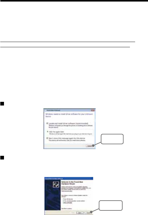
If you have connected the product to a PC without first installing the
driver, please make sure to press [Cancel] in the [Installation Wizard]
window when it pops up the PC screen and then disconnect the USB
cable from the product.
For more details about the proper installation procedure, see the
Software Introductory manual that accompanies [RTR-500DC for
Windows ].
Windows Vista
[Cancel]
Button
For other Windows Operating Systems
* The screen shot below is from Windows XP. For other Windows OS, there is also a [Cancel]
button in the lower right of the screen. (Your screen may differ slightly if you are using a
Windows OS other than XP.)
[Cancel]
Button

2
About Data Collector RTR-500DC
Outline
Our revolutionary Wireless RTR-500 Series is a system wherein the
various kinds of data measured and recorded by our Data Logger units
(Remote Units) can be transmitted to the RTR-500DC Data Collector
(Base Unit) via short range radio communication. The Data Collector can
then be connected to your computer to enable easy downloading and
total data management.
Compatible Data Loggers: Wireless Data Logger
RTR-501/502 Temperature data
RTR-503:Temperature and Humidity data
RTR-574: Illuminance, UV Intensity, Temperature and Humidity data
Basic Functions
- Wireless Data Communication Function
Our Wireless Data Logger RTR-500 Series utilizes the RTR-500DC to
collect recorded data from the Data Logger Units via our exclusive short
range wireless technology. The RTR-500DC also allows you to wirelessly
control recording settings and start recording, as well as other functions of
the Data Loggers. Communication is possible to a distance of up to 500 ft
(1150) if unobstructed and direct.
Note
- If collecting data via wireless communication, it is necessary to first set up the
RTR-500 Series Units as Remote Units in your computer.
- Register up to 224 Remote Units on 1 RTR-500DC
RTR-500DC is designed to manage the RTR-500 Series Units (Remote
Units) in groups. 1 RTR-500DC Unit can be set up to manage up to 7
groups, with each group containing up to 224 Units.
- Monitoring Function
With RTR-500DC, you can wirelessly monitor current temperature readings
of one group of Remote Units, with the readings being sequentially
displayed on the unit.
Note
If monitoring is carried out on a regular basis the battery life of the Remote Units will be
shortened.
3
- Data Storage Capacity: 256,000 Readings
The RTR-500DC has a large enough capacity to collect data from 16
Remote Units at full storage capacity.
- Graph Display
The RTR-500DC gives you a high quality graph display of collected data
whether it be temperature, humidity, illuminance or UV. By using the handy
operation dial or the buttons on the front of the main unit you can easily scroll
left and right across the graph display; giving you the data you want in an
easy to check format.
- Radio Wave Monitor
Check the condition of radio wave transmissions.
- Handy Operation Dial
By simply moving the dial up and down you can scan the menu and make a
selection by simply pressing in on the dial.
- Manage Recording Start / Stop without a Computer
Besides controlling the collection of data, the RTR-500DC can manage
recording settings such as: Programmed Recording Settings and Immediate
Record. This enables the user to easily control various recording settings for
a variety of models on-site without the need for a computer.
- Battery Life Warning Display
When the battery power goes low, a battery life warning will be displayed. If
the battery is not changed the RTR-500DC will automatically go into sleep
mode.
- Trustworthy Backup Function
If, after the battery warning display appears, the battery power goes even
lower the RTR-500DC will automatically go into sleep mode. Although, in
sleep mode, the unit cannot be operated and power cannot be turned on, all
data will be safely stored without loss.
Note
- If after going into sleep mode, the battery is not changed for about 1 month, or if the
battery is left out of the RTR-500DC for more than 2 minutes, all data will be lost.
4
- Over 96 Hours on 2 Alkaline Batteries
The RTR-500DC takes advantage of our exclusive circuitry design to bring
over 96 operating hours worth of power on only 2 AAA alkaline batteries.
Energy efficiency is further enhanced with our Auto Power Off Function.
Note
- Battery Life varies according to type of battery, measuring environment, transmission
frequency, and ambient temperature. This estimate of battery life was based on
normal use under normal conditions using a new batteries. This is in no way or
manner a guarantee of battery life.
- Auto Power Off Function
To save battery energy the RTR-500DC will automatically be turned off
when not in use for 3 minutes.
- Backlight Display for Viewing in Dark Places
The RTR-500DC comes equipped with a backlight display for easy viewing
even in hard to see places. The light can be switched ON/OFF in the main
menu. If set to be ON, it will light up when operation begins and
automatically turn off when operation stops for a few seconds, saving
battery energy.
Note
- If an outside power source is being used, the back light function will normally be ON.
5
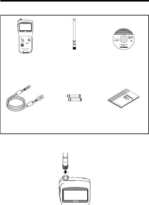
Contents of Package
The following items are included in the package.
Data Collector
RTR-500DC x 1
Antena x1 Software CD-ROM x 1
(RTR-500DC for Windows)
USB Communication
Cable x 1
AAA Alkaline
Batteries x 2
Introductry Manual
and Warranty x 1
Connecting the Antenna
Connect the supplied antenna to the antenna connector.
6
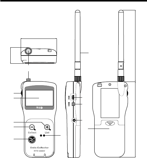
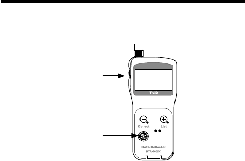
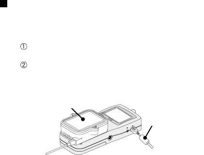
Appearance Diagram and Part Names
①
②
③
⑤
④
⑥
⑦
⑨
⑧
⑩
⑪
⑫
109
125
58
26.3
(Unit : mm)
① Antenna Connector ⑧ Antenna
② Operation Dial ⑨USB cable connection jack
③ LCD Display ⑩RS-232C Communication cable connection jack
④List Button ⑪ AC adaptor connection jack
⑤Collect Button ⑫ Battery Compartment
⑥ Power ON/OFF Button
⑦ Optical Communication Area

7
Installing the Software
Make sure to install the software before connecting the
Unit to a PC with the USB cable.
If you have connected a Unit to your computer before installing the USB
device driver, make sure to click the [Cancel] button in the Wizard window
when it pops up on the computer display. Then disconnect the USB cable
from the Unit.
Before Installing the Software
Is Windows working properly?
If Windows is not operating properly, the software may not be installed
correctly or it may not operate properly.
Make sure to check that the OS you are running and “RTR-
500DC for Windows”are compatible.
Microsoft Windows 7 32/64bit English
Microsoft Windows Vista 32bit English
Microsoft Windows XP 32bit (SP2 or above) English
- For details about the necessary operating environment, see page 51.
Quit all other applications
If you are running other applications, make sure to quit them before
installation. If you have any permanently active software, such as a virus
check or scan program in your computer, make sure to also quit it.
To install “RTR-500DC for Windows”, it is necessary to have
Administrator rights (Computer Administrator) for the computer
in which you wish to install it.
8
Procedure for Installing the Software
This explanation uses displays from Windows XP SP2.
- If your OS is Windows Vista or Windows 7, the window layout may be
slightly different. However, the message contents and the button operations
are the same, so please follow the directions as written below.
1. Open Windows.
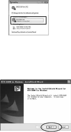
2. Place the supplied software (CD) into the CD-ROM drive.
The "Install Program" window will appear soon.
* In Windows Vista or Windows 7, if
the [Auto Play] window appears,
click on "Run Start.exe".
If the "Install Program" window does not automatically open, please
open it by double clicking on the CD drive icon in [My Computer].
3. Select "Install RTR-500DC for Windows" and click the
[Execute] button to start the installation.
4. The "RTR-500DC for Windows" Setup Wizard window will
appear.
Click the [Next] Button
9
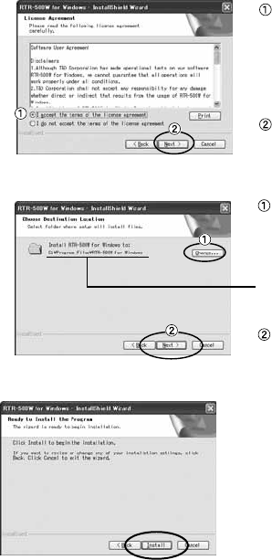
5. The "Software License Agreement" window will appear.
Please read all the
terms stipulated in the
agreement. Check "I
accept the terms of the
license agreement" if
you accept the terms.
Click the [Next] button.
6. The "Choose Destination Location" window will appear.
Click the [Next] button.
By clicking the
[Change] Button it is
possible to change the
installation folder.
Info for file to be
installed
7. The "Ready to Install the Program" window will appear.
Click the [Install] Button to
begin installation.
10
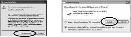
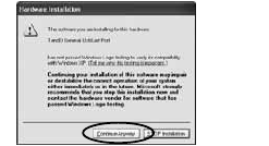
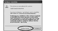
Although a warning message such as below may appear, there is
no problem, please move on to the next step.
Warning Message
For Windows XP
Click the [Continue Anyway] Button
For Windows Vista and Windows 7
Click the [Install] Button
8. After installation has been completed, "RTR-500DC for
Windows" will be registered in the Window's [Start] Menu.
After having installed the supplied software it is necessary
to install the USB Device Driver.
- See the following pages for details.

11
About USB Device Drivers
Have you installed the software?
Before connecting a Unit to a PC with a USB cable make sure to install the
Software first.
For Units using a USB connection, it is necessary to first
install the Software, and upon connecting the Unit to the PC
with a USB cable it is necessary to install the USB Device
Driver. A USB Device Driver enables the PC to recognize
the connected device and ensure proper operation.
- To ensure a proper connection, make sure that the USB cable is inserted fully.
- Login using a User Account with Administrator (Computer Administrator)
rights.
Users of Windows XP must carry out the Installation
Procedure.
Upon connecting a Unit to your PC, the [New Hardware Detection Wizard] will
automatically open. Please carry out the procedures on the following pages to
install the USB Device Drivers for the Base Unit (RTR-500DC), Remote Units
(RTR-574), and if necessary, Repeaters (RTR-500).
- In XP, if the Wizard window does not automatically open, installation may have
not been fully completed or failed. Please check the USB device driver.
Users of Windows Vista or Windows 7 do not have to
carry out this installation.
By installing the supplied software, the USB Device Drivers for the Base Unit,
Remote Units and Repeaters will also be automatically installed. It is not
necessary to carry out any extra steps to install the USB Device Drivers.
- See page from 28 of this Manual for about how to confirm that the
USB Device Driver has been properly installed.
12
Procedure for Installing
the Base Unit USB Device Driver
Carry out all USB Device Driver installations for only
one Unit at a time.
Users of Windows XP should carry out the following procedure to install the
USB Device Driver.
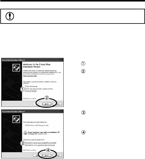
1. By connecting a Base Unit to your computer, the [New
Hardware Detection Wizard] will automatically open.
- The “Wizard” window will only appear upon the first connection.
Check "No, not this time".
Click the [Next] Button.
Check "Install the software
automatically (Recom-
mended)".
Click the [Next] Button.
13
2. The installation process will begin.
If a warning message window
appears, click the [Continue
Anyway] button, and continue with
the installation.
3. Once the completion message appears, installation has
finished.
Click the [Finish] Button.

14
Procedure for Installing the RTR-574 /
Repeater USB Device Driver
Carry out all USB Device Driver installations for only
one Unit at a time.
Users of Windows XP should carry out the following procedure to install the
USB Device Driver.
1. By connecting a Remote Unit (RTR-574) or a Repeater to
your computer, the [New Hardware Detection Wizard] will
automatically open.
The “Wizard” window will only appear upon the first connection.
Check "No, not this time".
Click the [Next] Button.
Check "Install the software
automatically (Recom-
mended)".
Click the [Next] Button.
2. The installation process will begin.
15
If a warning message window
appears, click the [Continue
Anyway] button, and continue with
the installation.
3. Once the completion message appears, installation has
finished.
Click the [Finish] Button.
- See page from 16 of this Manual for about how to confirm that the
USB Device Driver has been properly installed.
16
Checking a USB Device Driver
Check the USB Device Driver installation for one device
at a time.
The checking procedure is the same for the Base Unit,
Remote Units and Repeaters.
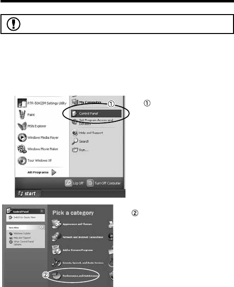
Check using the following steps:
1. Open the Device Manager window.
Procedure example:
In the Windows Start
Menu, click on "Control
Panel" to open.
Click on "Performance and
Maintenance".
17
Click on "System".
In the System Properties
Window, click on the
[Hardware] tab.
Click the [Device Manager]
Button.
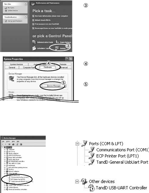
2. Connect the target Unit to the computer with a USB cable
and look at the icon displayed in the Device Manager
window in order to check whether or not the USB Device
Driver has been properly installed.
If failed (example)
If successful (example)

18
If the icon appears with an " ? " or an " ! ", the PC is not
properly recognizing the Unit.
Windows XP Windows Vista /
Windows 7
3. If your PC does not properly recognize a Unit, please
re-install the USB Device Driver by following the directions
on the next pages.
19
Re-installing the USB Device Driver
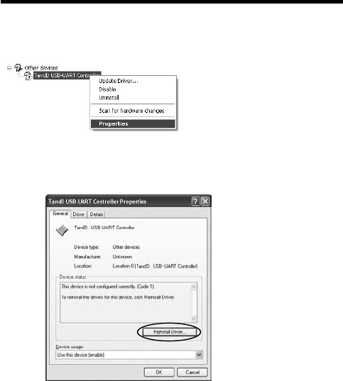
1. Right click on the icon.
2. From the pop-up menu click on "Properties" .
3. When the following window appears, click on the [Reinstall
Driver] button to display the Wizard window.
[General] Tab Window
[Reinstall Driver]
Button
20
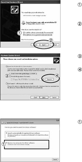
4. If you are using Windows XP, please follow the directions
below and move on to step 6.
Check the "Install from a list
or specific location
(Advanced)".
Click the [Next] Button.
Check the "Include this
location in the search:".
Click the [Browse] Button.
5. If you are using Windows Vista or Windows 7, please follow
the directions below.
Click the "Browse my
computer for driver software".
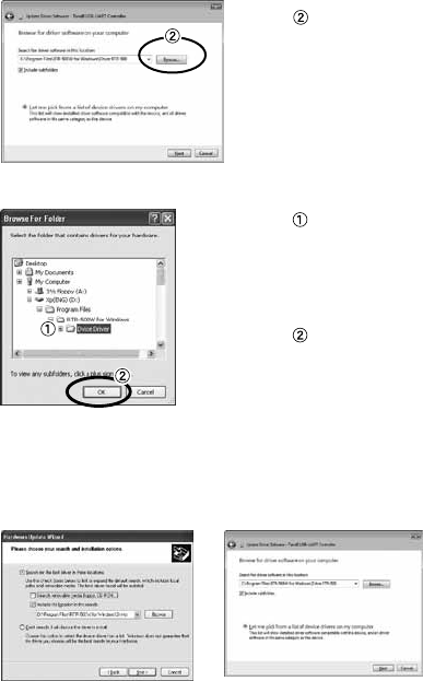
21
Click the [Browse] Button.
6. Specify the location of the Driver.
Click the plus (+) sign next to
the folder into which the
software was installed and
specify "Device Driver" as
the driver location.
Click the [OK] button to
return to the Wizard window.
7. In the Wizard window, check to make sure that the Driver is
specified correctly. Then click the [Next] button.
For Windows XP For WIndows 7 and Windows Vista
Location Example:
C:\Program Files\RTR-500W for Windows\Driver RTR-500
22
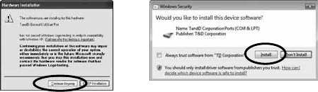
8. The installation process will begin.
Please note that the following warning messages may appear during
installation. However, this will cause no problems with USB device
driver installation. Please move on to the next step.
Warning Message
For Windows XP
Click the [Continue Anyway] Button Click the [Install] Button
For Windows Vista and Windows 7
9. After installation has been completed, please click the
[Finish] or [Close] button.
10. Check to make sure that the USB Device Driver has been
properly installed.
See page from 16 of this Manual for details.

23
Explanation of the Button Functions
- When downloading via wireless communication the [Select
Group] display will appear.
- Allows you to swift-scroll across data when viewing a graph
or an event list.
- The downloaded data list will be displayed.
- Allows you to swiftly make changes to the upper and lower
limit value settings.
- Switch Power ON/OFF.
24
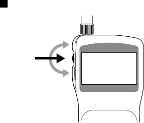
How to Use the Operation Dial
Press in
Move
the dial up
Move
the dial down
[Moving the dial up and down]
- By moving the dial up or down the arrow will move to allow you to choose
the desired item. The selected part will be displayed in an easy-to-see
inversed shade.
- When setting a numerical value, by moving the dial up the value will become
larger and by moving the dial down the value will become smaller.
[Pressing in on the dial]
- Switching the Power On.
- You cannot switch the power OFF with the operation dial. Press in on the
<POWER> button.
- By pressing in on the dial, you can make a desired menu selection or
complete and activate a setting.
- Keeping the dial pressed in (1.5 seconds) will activate different functions
depending on the display being viewed.
If you keep it pressed in while viewing the graph display, you can change the display
channel.
25
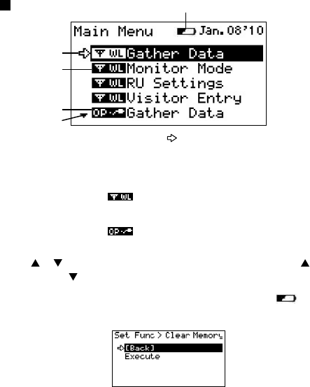
LCD Display
①The item marked with an arrow [ ] denotes it has been selected. If
you move the operation dial up and down, the arrow will move
accordingly and by pressing in the dial the item selected will be
activated.
②Items marked with [ ] indicate menus for Wireless
Communication.
③Items marked with [ ] indicate menus for Optical / Wired
Communication.
④ A [ ] [ ] indicates that there are more menu items above [ ] or
below the [ ] to view.
⑤ When battery life goes low, a battery life warning mark [ ] will be
displayed to inform you it is time to replace the battery.
If there is a [BACK] is displayed, adjust the arrow to [BACK] and press it to
complete the setting and take you back to the menu display.
①
③
④
⑤
②
26
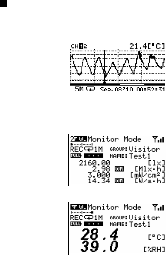
Recorded Data Displays
Graph Display
Valious measurement Data that has been downloaded to an RTR-500DC unit
can be displayed in Graph form.
Current Readings Monitoring
The RTR-500DC can be set to patrol and monitor Remote Units groups and
display in order the current readings for view.
27
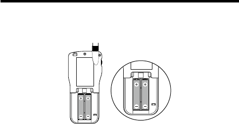
Installing the Batteries.
Two AAA type Alkaline, or Ni-MH (1.2V) batteries may be used, but
be sure not to mix types of batteries and to insert them in the correct
direction to align + and -.
Note
- The RTR-500DC unit has no battery recharging ability.
- If using an outside power source, batteries are not necessary.
About Battery Life
When battery life goes low, a battery life warning mark will be
displayed to inform you it is time to replace the battery. If battery life
goes even lower, the Unit will automatically go into sleep mode in
order to save data.
- In sleep mode, the Unit cannot be turned on or operated as usual.
- When replacing the battery, if the battery has been removed for more than five
minutes, the data stored in the Unit may be erased. It is recommended to first
download any necessary recorded data to your computer before replacing the
battery.
- Also, you will lose all data if the battery drains completely; make sure to
replace the battery as soon as possible.
28
POWER and Auto Power Off Function
Switch the power ON by pressing the <POWER> button or the
Operation Dial. To switch the power OFF, press the <POWER>
button. You cannot switch the power OFF with the Operation Dial.
Press the
Operation Dial
or
<ON/OFF>
Button
[Auto Power Off Function]
If the main unit is not in use for 3 minutes, the power will be automatically
switched off in order to save battery power. If you wish to continue to use,
switch the power on again.
Note
- If using the monitoring function, the Auto Power Off function will not go into
effect.
- AUTO power OFF is not done while being connecting USB or AC adaptor.
29
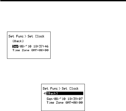
Setting the Date and Time
Follow the procedure below to make clock settings for the Unit.
1.
In the Main Menu, go to [Set Functions] and select [Set Clock].
2.
Set the desired values.
(1) Moving the Operation Dial up and down
will change the selection item of the
display in the order of month, day, year,
hour, and minute. By pressing the dial, the
value for that item will flash.
(2) Change the value by moving the dial up
and down. Press the dial again to set the
selected value and move to the next
settings item.
3.
After having completed the clock settings, move the arrow to [Back] and
press the dial to return to the Menu Window.
[Time Zone]
By setting the region in which the Unit will be used the time difference will be
automatically set. Daylight Savings Time settings must be set manually.
- Please make sure that the date and time settings in the Unit is correct, if it is
not, the recording start time and recording time of downloaded data will be
incorrect.
- Clock settings for the Unit can also be made from your computer by using the
software supplied with the Unit. For more details, see the [Help] Menu in the
supplied software or the User’s Manual that accompanies it.
30
Communicating with the Computer
For direct communication with your computer to download or make
setting changes, etc... please use a USB communication cable
(provided) or the serial cable (optional).
You can transfer the registration contents from one RTR-500DC to
another via the attached software. For details see the [Help Menu] in
“RTR-500DC for Windows” or the Introductory manual that
accompanies it.
Note
- Communication with a computer cannot be carried out while a wireles
communication session is occuring
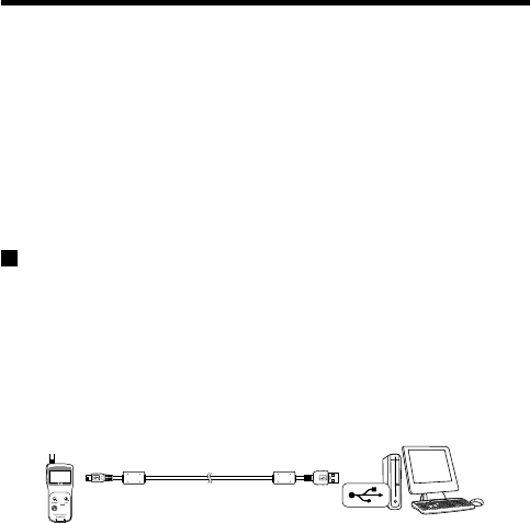
For USB
Communication between RTR-500DC and your
Computer
You will need to install the USB Device Driver in order to use the
device with a USB cable and Windows. After installing, your
computer will be able to detect and recognize an RTR-500DC
device that has been connected with a USB cable.
USB mini-B
To the RTR-500DC
USB A
To the computer
Included
USB Cable (US-15C)
31
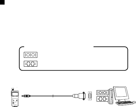
For Serial (Use Optional Cable)
Communication between RTR-500DC and your
Computer
1. Connect the Serial Communication Cable to a serial port on your
computer.
2. Connect the Serial Cable to the COM port on the RTR-500DC.
The cable connection is a D-sub 9pin male.
Please connect to the place that has such a
symbol.
Examples of Serial Port Symbols
RS-232C Communication
cable connection jack
D-Sub9 Pin male
to PC
Optional Serial Communication Cabe
(TR-07C)
Note
- Be sure the connections are correct. If wrong, communication will not be possible.
- To prevent faulty contact, make sure to fully insert the communication cable until you
hear a "click" sound.
32
Communication between RTR-501/502/503,
and your Computer
1. Connect the communication cable.
Connect the RTR-500DC Unit to your computer with the provided
communication cable. (USB or RS-232C)
Place the Data Logger on the RTR-500DC.
2. In order to carry out wireless communication, register Groups and
Remote Units.
Place the unit face down
on the RTR-500DC.
Communication Cable
(to computer)
Note
- If light enters during communication, an error will occur. Please make sure to place
the unit within the ridges for an exact fit.
- For details about how to register, see the [Help Menu] in the provided software
[RTR-500DC for Windows ] or the accompanying Introductory manual.
33
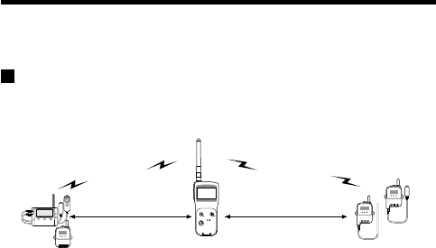
Communicating with the Data Logger
There are two ways to communicate between the RTR-500DC and
the Data Logger.
Wireless Communication
Communication can occur via special short radio waves with the
Remote Units.
Radius
150m (500ft)
Radius
150m (500ft)
Note
- Wireless communication can only occur with those RTR-501/502/503 and RTR-574
logger units that have been registered as Remote Units via the accompanying
software RTR-500DC for Windows.
The following operations can be done using Wireless
communication.
- Download Recorded Data
You can download data to the RTR-500DC that has been recorded in Remote Units from a
distance, without having to collect the units.
- Change Recording Conditions
You can control and change Recording Start Date and Time (Programmed Start).
- Monitor Current Readings
You can monitor the current measurements of a Remote Unit at a set interval or in groups
with the measurements displayed consecutively.
34
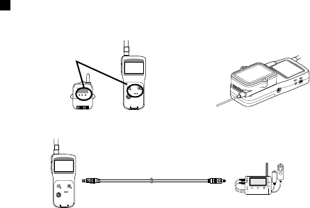
Non-Wireless Communication
Optical Communication for RTR-501/502/503
Optical Communication
Area
Place logger face
down on RTR-500DC
Via Optional Communication Cable for RTR-574
Connect using the optional
communication cable TR-6C10
The following operations can be done using communication via cable
or optical communication.
- Download Recorded Data
You can download any data that has been recorded in a Data Logger.
- Set the Recording Conditions
You can control and change Recording Start Date and Time (Programmed Start).
35
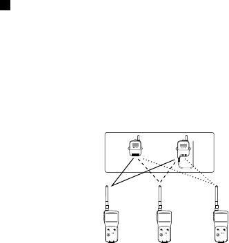
One Remote Unit can be set up to communicate
with any number of RTR-500DC Units.
By registering the same Remote Unit info into a number of RTR-
500DC Units it is possible to check and control settings, as well as
download to any RTR-500DC Unit that carries that Remote Unit's
registration information.
Note
- If you try to carry out communication between one Remote Unit and several
RTR-500DC Units at the same time, an error message will appear.
Remote Units
36
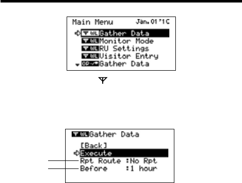
Wireless Functions: Gather Data
Downloading Recorded Data
1.
In the Main Menu, open [ WL Gather Data] .
2.
Choose a Group.
3.
Select the Remote Unit you wish to download the data from.
4.
Press on [Execute].
①
②
① Rpt Route : Repeater Route
Choose from No Rpt (No Repeter) or Obey Reg (Obey Register)
②Before :Period of Data
You can set the period (how many hours or days before now) from which
you wish to download data.
- You can select from 1 to 47 hours (in 1 hour units) / 2 to 300 days (Less than
300 days in units of 1 day, or ALL DATA.
- If you specify the period of data that is earlier than the period of the data
saved in the remote unit, all saved data will be downloaded.
5.
Press on [Execute].
37
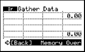
If Downloading Recorded Data Fails
If there is not enough memory remaining, the message [Memory Over] will
appear and downloading will stop. Please save recorded data from the TR-57DCi
to your PC and delete unnecessary data from the TR-57DCi to make space for
downloading new data from the Data Logger.
38
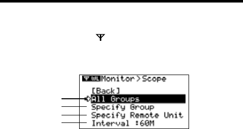
Wireless Functions: Monitor Mode
Monitoring Current Readings
The RTR-500DC can be set to patrol and monitor Remote Units
groups and display in order the current readings for view.
1.
In the Main Menu, open [ WL RU Settings] and then Select [Monitor
Mode] .
2.
Select the monitoring range and Set the monitoring interval.
3.
Press Operation Daial.
①
②
③
④
①All Groups
Remote Units in all groups registered to the RTR-500DC will be contacted
via wireless communication.
②Specify Group
All Remote Units in the selected groups will be contacted via wireless
communication.
- If you wish to monitor using the [All Groups] range, it is possible to monitor only 120
Remote Units. Therefore, when making changes to the [Set Number of Possible
Registrations] make sure to register no more than 120 Remote Units to the Group or
use the [Specify Group] range as oulined below.
③Specify a Remote Unit
All Remote Units in the selected groups will be contacted via wireless
communication.
④Interval
The monitoring interval is the amount of time between the starting
of wireless communication to gather current Remote Unit readings.
Selections can be made from 10 sec to 60 minutes (in 1 minute units).
- The amount of communication time depends on the number of registered groups
and remote units. Please note that if the monitoring interval is set for less time than
communication takes to complete a round of monitoring, the system will
automatically extend the interval to allow for the necessary amount of communication
time.
39
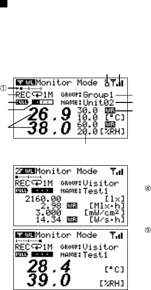
Monitor Mode Display
Current measurement readings for those units with which
communication is possible will be displayed consecutively every 2
seconds. For those units with which communication is impossible
the measurement will be displayed as [----].
⑥
⑦
⑧
⑨
⑪ ⑩
③
②
① The number of the cordless
handsets displaying a cross
axle
②Recording Status, Recordeing
Mode Icon, Recording Interval
(S: Seconds , M: Minute)
③Battery Status of Remote Unit
Quantity of current record
readings
⑤Value of current readings
⑥ Upper / Lower Limit
⑦ Warning result
⑧Remote Unit Name
Group Name
⑩The strength of the wireless
Radio wave at the time of the
latest communication with the
monitor
⑪ When there is it via Repeater, it
is displayed
For RTR-574
For RTR-501/502/503
⑤
④
40
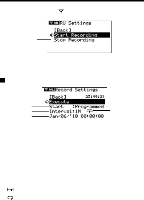
Wireless Functions: RU Settings
Start / Stop Recording Remote Unit
1.
In the Main Menu, open [ WL RU Settings] and then Select [Start
Recording] or [Stop Recording] .
①
②
2.
Choose a Group in select menu.
3.
Select a Group in which Remote Units are registered.
4.
Press on [Execute].
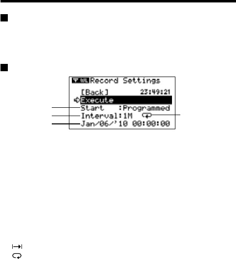
Record Settings
①
②
③
④
①Start (Recording Start)
Choose from Immediate Start / Programmed Start
②Interval (Recording Interval)
It is not possible to set it with the Unit. The content set with the dedicated
software is displayed.
③Start Date and Time
If you are making changes to a programmed start, make sure to set start
time.
④Recording Interval and Recording Mode Icons
It is not possible to set it with the Unit. The content set with the dedicated
software is displayed.
One Time: Recording will stop when the data capacity becomes full storage
Endless: Recording will continue with oldest data continuously overwritten.
41
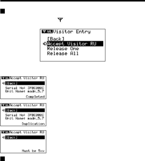
Wireless Functions: Visitor Entry
Entry / Release Visitor Remote Unit
Accept Visitor RU (Remote Unit)
1.
In the Main Menu, open [ WL Visitor Entry] and then Select [Accept
Visitor RU] .
2.
Press on Operation Dial.
Completed
Vistor Entry Completed, shows Serial No, of Remote
Unit. and Unit Name on this Units has given automaticaly
Duplication
Vistor Entry Completed, shows Serial No, of Remote
Unit. and Unit Name on this Units has given automaticaly
Incompatible
The unit accept RTR-500 series Data Loggers only.
Release One / ALL
Select the Visitor Remote Unit you wish to Release from [Release One]
or [Release All] and Press on [Execute].
42
Non-Wireless Communication Functions
Gather Data
Connect the RTR-500DC to the Data Logger either by placing it on
the Collector for optical communication or connect via the optional
communication cable.
Record Settings
①
②
③
④
①Start (Recording Start)
Choose from Immediate Start / Programmed Start
②Interval (Recording Interval)
Choose from :
10~59 S (seconds) per second / 1~ 60 M (minutes) per minute
③Start Date and Time
If you are making changes to a programmed start, make sure to set start
time.
④Recording Interval and Recording Mode Icons
It is not possible to set it with the Unit. The content set with the dedicated
software is displayed.
One Time: Recording will stop when the data capacity becomes full storage
Endless: Recording will continue with oldest data continuously overwritten.
43
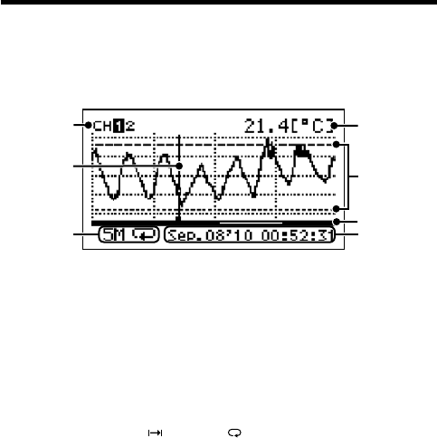
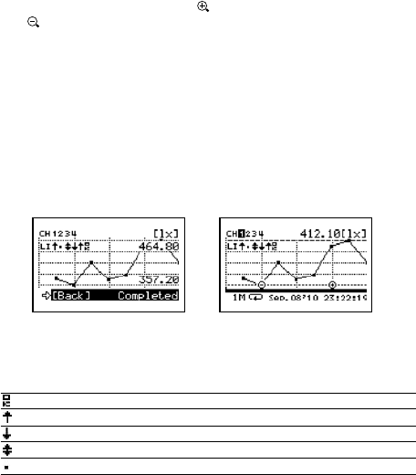
Data List: Display Graph
In this display you can view in graph form the recorded data col-
lected by the Unit. A graph is displayed for each channel of data
and can be scrolled left and right with the Operation Dial or by the
buttons on the Unit.
1.
2.
3. 7.
4.
6.
5.
1. Displayed Channel
If there are multiple channels of recorded data, you can change the channel on
display by holding in the Operation Dial (for about one second).
2. Cursor
By moving the Operation Dial, you can scroll the cursor left and right to view
the recording date and time and measurement for that point where the cursor is
positioned.
3. Recording Interval and Mode
The “Recording Interval” and “Recording Mode” for the displayed data are
shown here.
S: Seconds, M: Minutes, : One Time, : Endless
4. Measurement at Cursor Position
The corresponding measurement value is displayed for the date and time
where the cursor is positioned.
[°C/°F]: Temperature
[%RH]: Humidity, [hPa]: Barometric Pressure
[lx]: Illuminance
[mW/cm2]: UV Light
5. Upper and Lower Limit
If Upper and/or Lower Limits have been set in the Data Loggers these limits will
be shown using dotted lines.
44
6. Graph Display Range
From the entire range of recorded data this line shows the range of data
currently on display. You can use the< List> button on the Unit to zoom in and
the < Collect> button to zoom out on data.
7. Date and Time of Cursor Position
The date and time of the current cursor position are shown here.
Upper and Lower Limit Judgment
Upper and/or Lower Limits are set when making Recording Start settings
from a PC. When downloading recorded data from Remote Units for
which Upper / Lower Limits have been set, the judgment result will be
displayed automatically upon completion of the downloading and at the
time of graph display.
Upon Completion of
Downloading
At Time of Graph Display
(shows for about 5 seconds)
Reading Judgment Results
Starting from CH1, the results will be displayed in rotation.
: No measurements were over the set limits.
: One or more measurements exceeded the Upper Limit.
: One or more measurements exceeded the Lower Limit.
: Measurements exceeded both the Upper and Lower Limits.
: Upper and Lower Limit Settings were not made.
45
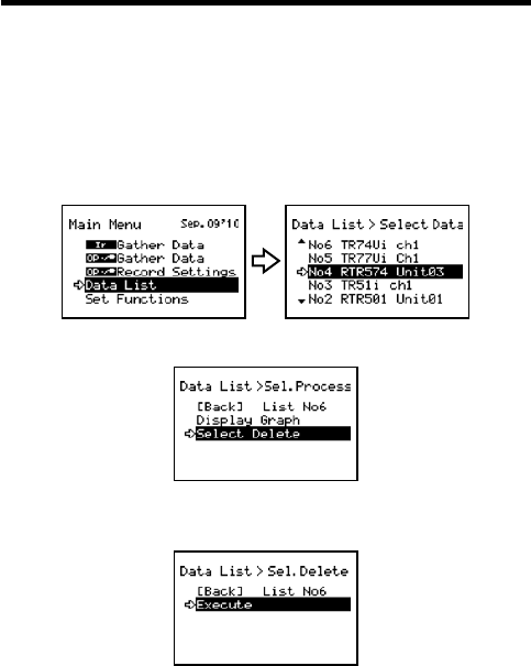
Data List: Deleting Data
All downloaded data is temporarily saved in the Unit. It is possible to
select it for deletion.
Deleting Selected Data
1.
In the Main Menu, open [Data List]. Select the data you wish to delete
and press the Operation Dial.
Main Menu Select data
2.
Move the arrow to [Select Delete] and press the Operation Dial.
3.
A confirmation screen will appear. Select [Execute] to delete the
selected data or [Back] not to delete it, and press the Operation Dial.
4.
Upon completion of deletion, it automatically returns to the data
selection display.
- When you want to delete all data, please execute [Memory Clear] in [Set
Functions] .
46
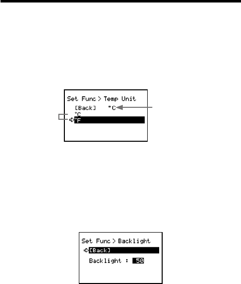
Set Functions: Operational Settings
By changing the Unit of Temperature, the Recorded Data display in the
Unit and the LCD display on the target Remote Unit(s) for which
recording was started from the Unit will be also be changed to reflect the
new setting.
■Set Temp Unit : Changing Unit of Temperature
1.
In the Main Menu, open [Set Functions] and [Set Temp Unit].
Current Setting
Select
2.
Move the arrow to [°C] or [°F] and press the Operation Dial.
Default value: [°F]
3.
Move the arrow to and click on [Back] to return to the Main Menu.
■Set Backlight : Adjusting the Backlight
1.
In the Main Menu, open [Set Functions] and [Set Backlight].
2.
Move the Operation Dial up to make the light brighter and down to
make it darker.
Default value: 80 (OFF, 1 to 100)
3.
Press the Operation Dial to return to the Main Menu.
The backlight maintains lighting while connecting the AC adaptor.
47
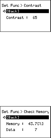
■Set Contrast : Adjusting Contrast
1.
In the Main Menu, open [Set Functions] and [Set Contrast].
2.
Move the Operation Dial up to make the display darker and down to
make it lighter.
Default value: 65 (0 to 100)
3.
Press the Operation Dial to return to the Main Menu.
■Check Memory:
Checking Storage Capacity of the Unit
1.
In the Main Menu, open [Set Functions] and [Check Memory].
2.
Press the Operation Dial to return to the Main Menu.
48
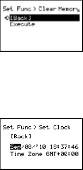
■Clear Memory:
The memory of the Unit is adjusted to Zero.
1.
In the Main Menu, open [Set Functions] and [Clear Memory].
2.
Press on the Execute.
■Set Clock: Making Clock Settings
1.
In the Main Menu, open [Set Functions] and [Set Clock].
2.
Select the item you wish to change and press the Operation Dial.
3.
Move the Operation Dial up and down to adjust clock.
4.
Move the arrow to and click [Back] to return to the Main Menu.
49
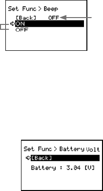
■Beep: Muting the Operation Beep
1.
In the Main Menu, open [Set Functions] and [Beep].
Current Setting
Select
2.
Move the arrow to either [ON] or [OFF] and press the Operation Dial to
confirm.
3.
Move the arrow to [Back] and press the dial to return to the Main Menu.
■Battery Voltage: Checking Battery Voltage
1.
In the Main Menu, open [Set Functions] and [Battery Voltage].
2.
Press the Operation Dial to return to the Main Menu.
Battery Voltage:
When battery power depletes to about 2.30V, the battery life warning mark will
appear.
50
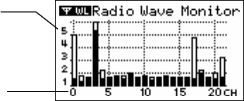
■Radio Wave Monitor:
Checking the Condition of Radio Wave Transmissions
Depending on the location of the logger, at special frequencies there
may be some instances in which, due to radio wave interference or
other causes, communication capability does not meet expected
standards. To help avoid interference and reduce the chances of
poor transmission, we suggest that before registering a Remote Unit
you check the condition of radio wave transmissions and when
creating a new Group assign the units to an empty frequency
channel.
The radio wave strength is displayed in a scale from 1 to 5, with the higher the number the
stronger the radio waves are.
Longitudinal axis:
Radio Wave Strength
(1 to 5)
Horizontal axis:
Frequency Channel
1.
From the Main Menu, select [SET FUNCTIONS].
2.
From the [SET FUNCTIONS] menu, select Radio Wave Monitor. (Wave
Check)
3.
Close the Radio Wave Monitor by pressing in on the operation dial.
(Returns to the [SET FUNCTIONS] Menu)
Note
- While using the Radio Wave Monitoring Function, the Auto Power Off Function will
be disabled.
51
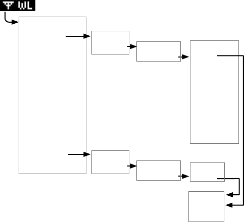
Menu List
GATHER DATA
[Back]
Group List [Back]
RU / VRU List [Back]
Execute
Repeater Rout :
No Rpt / Obey Reg
Specify Period of Data
to be Downloaded
Start
Downloading
Data
Canceled *
* It is possible to cancel by pushing the operation dial while Downloading.
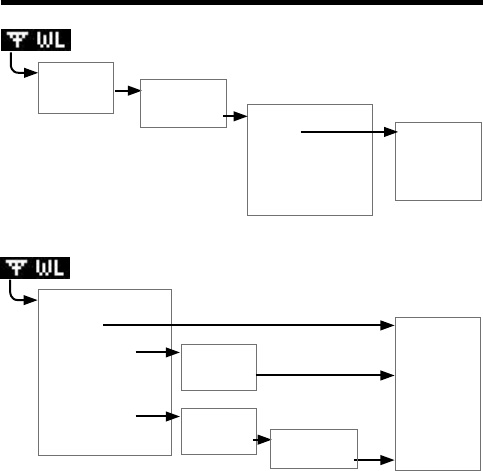
Monitor Mode
[Back]
Group List
[Back]
Group List
[Back]
All Groups
Specify a Group
Specify a
Remote Unit
Interval [Back]
RU / VRU List
Start Serching
Canceled *
* It is possible to cancel by pushing the operation dial while Serching.
52
RU Settings
[Back]
Group List
[Back]
Group List
[Back]
Start Recording
Stop Recording
[Back]
RU / VRU List
[Back]
RU / VRU List
[Back] Time
Execute
Start:
Programmed /
immImmediate
Interval *1
Recording
Mode*1
‘YY/MM/DD
XX:XX:XX *2
[Back]
Execute
[Back]
Confirmatin
Display
*1 Only the confirmation.
*2 Sets it for Programmed Start.
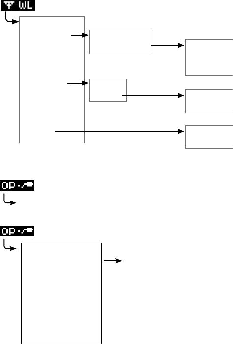
53
Visitor Entry
[Back]
Join VRU, Push Dial
[Back]
Vistor List
[Back]
Accept Visitor RU
Release One
Release All
[Back]
Serial No *
Unit Name *
[Back]
Execute
[Back]
Execute
* Only the confirmation.
Gather Data
Specify the period of data to be downloaded.
Upon completion of the download, a graph will appear.
Recording Settings
[Back]
Execute Send Recording Settings
to Remote unit.
Start
Interval*
REC Mode*
REC Mode*
YY/MM/DD XX:XX:XX *2
*1 Only the confirmation.
*2 Sets it for Programmed Start.
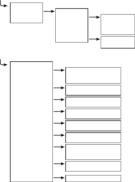
54
Data List
[Back]
Data List [Back]
Display Graph (Press Operation Dial
to display Graph)
[Back]
Continue
Select Delete [Back]
Execute
Set Functions
[Back]
Set Temp Unit Back
°C
°F
Set Backlight Back
OFF, 1 to 100
Set Contrast Back
0 to 100
Check Memory Back
Display Memory Usage (%)
Clear Memory Back
Execute
Set Clock Back
Settings
Beep Back
ON
OFF
Battery Voltage Back
Display Battery Voltage (V)
Radio Wave Monitor Display

55
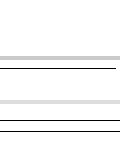
Specifications for RTR-500DC Data Collector
RTR-500DC Unit
Compatible Devices Remote Unit:
RTR-501/501L, RTR-502/502L, RTR-503/503L, RTR-574
Repeater : RTR-500
Recording Capacity 16 units at full storage capacity16,000 readings x16= 256,000
readings. Can hold up to 250 downloading sessions
Functions Downloading data (possible to display results of upper and
lower limit check after downloading)
Display Highest and Lowest Measurement after downloading
Display Saved Data Graphs
Set Recording Start for Remote Data Loggers
Delete stored data (one reading) / Clear Memory
Monitor Current Readings
Search for Remote Units Wave Check (5-level display of radio
wave strength for each channel (0-21ch.))
LCD Display Operation Menu, Graph Display, Low Battery Life Warning,
Calendar and Clock, Contrast Adjustment, Backlight
Power 2 AAA Alkaline Batteries (LR03)
AAA Ni-MH 1.2V batteries
Optional AC adaptor (AD-0638)
USB Bus Power
Battery Life* 96 hrs* under Continuous Operation :
Using 2 AAA Alkaline Batteries / Monitor Current Readings
60 sec. pitch / No Repeater
32 hrs* under Continuous Operation :
Using 2 AAA Alkaline Batteries / Checking the Condition of
Radio Wave Transmissions
730 Downloading Sessions for RTR-501 at full storage capacity
(calculated value)
via Wireless communication / No Repeater / No Backlight
function
* Battery life varies depending upon the type of battery, the measuring
environment, the frequency of communication, and the ambient
temperature in which it is used.
Data Backup About 1 month (Saved data will be erased if all battery power is
lost.)
Communication
Interface (with PC)
USB
RS-232C(RS-232C)
Communication
Interface
(with Data Logger)
Short Range Radio Communication
Optical Communication (RTR-50x) : 2,400 to 19,200 bps
RS-232C (RTR-574) : 9,600 to 19,200 bps
56
Interface
Communication Time
When downloading one Remote Unit at full storage capacity:
Data from RTR-500DC to PC
USB : 12 sec (1ch) / 24 sec (4ch)
RS-232C: 22 sec (1ch) / 42 sec (4ch)
Data from Remote Unit to RTR-500DC
Optical: 170 sec (RTR-50x)
RS-232C: 45 sec (RTR-574)
Dimensions H125mm x W58mm x D26.3mm (excluding Antenna Connector)
Antenna Length: 109mm
Weight About 127g (including 2 AAA Alkaline batteries)
Operating Conditions Temperature: 0 to 50°C,
Humidity: 90 % RH or less (no condensation)
Other Not waterproof, moistureproof, or dustproof
Short Range Radio Communication
Radio Standard
Specifications
FCC Part15 Section247 / IC RSS-210
Frequency Range: 902 to 928MHz
Communication Range About 150m if direct and unobstructed.
Communication Time When downloading one Remote Unit at full storage capacity:
RTR-50x About 120 sec. *
RTR-574 About 240 sec *
* The same amount of time will be necessary for each added Repeater.
Software (RTR-500DC for Windows)
Operating Environment
Compatible
Devices
Base Units: RTR-500DC
Remote Units: RTR-501/501L, RTR-502/502L, RTR-503/503L,
RTR-574
Repeater: RTR-500
Compatible OS Microsoft Windows 7 32 / 64bit English
Microsoft Windows Vista 32bit English
Microsoft Windows XP 32bit (SP2 or above) English
PC/CPU A Stable Windows Operating Environment
Memory A Stable Windows Operating Environment
Hard Disk More than 30 MB of free space (More free space is necessary for data)
Monitor
SVGA (800 x 600) more than 256 colors
57
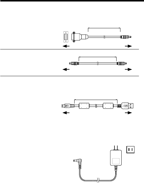
Optional Accessories
RS-232C Communication Cable
[unit: mm]
TR-07C
RS-232C Communication Cable
Cable Length: 1.0m (40 in)
Connector Type:
Specialized Connector D-sub9pin
1500
TR-6C10
Cable Length: 1.0m (40 in)
USB Communication Cable
[unit: mm]
US-15C
Cable Length: about 1.5m (60in)
1500
AC Adaptor
AD-0638
Input: AC100-240V
Output: DC6V 500mA
Frequency: 50/60Hz
Cable length: 1.85m (74in)
Plug Figuration: A
To RTR-500DC
To RTR-500DC
To PC
To PC
To RTR-574
To RTR-500DC
1000

For product information or questions contact us at:
817-1 Shimadachi, Matsumoto, Nagano, JAPAN 390-0852
Fax: +81-263-40-3152 E-mail: support@tandd.com
Website
http://www.tandd.com/
We have opened an English Website for your convenience. Here you can find
information about our company, news, products, upcoming events, software and
Introductory manual downloads, as well as, other support. Please stop by and
see what we have to offer.
Data Collector RTR-500DC
Introductory manual
Published by T&D Corporation (1st Edition)
© Copyright T&D Corporation. All rights reserved.
This is printed on recycled paper.

Data Collector RTR-500DC Warranty
Customer's name:
Address:
Phone No.:
Dealer's name:
Address:
Phone No.:
Guarantee period 12 months from date of purchase
Date of purchase
Provisions for Free Repair
1. If the Unit does not work properly despite the fact that the customer used it properly and in
line with the manual, the Unit shall be repaired free of charge through the distributor which
sold the Unit.
2. If the customer requests free repair because of trouble within the warranty period, bring or
send the Unit along with the warranty to the distributor.
3. If you have moved after purchasing, or there are difficulties contacting the distributor from
which you purchased the Unit, please contact T&D directly for service.
4. Free repair is not available in the following cases even though it is within the warranty
period:
1. Trouble or damage was caused by careless operation, natural disaster, fire, public pollution, or use of a power
source other than specified.
2. If repair, adjustment, disassembly or modification of the Unit has been carried out by a person other than a T&D
authorized engineer.
3. Trouble or damage was caused by transportation, movement or dropping of the Unit after purchase.
4. Failure to submit the Warranty or failure to fill in all items required in the Warranty.
5. The Warranty cannot be reissued.
This Warranty only promises customers free repair within the period and conditions clarified
in this Warranty. Therefore, the customer’s legal rights will not be limited by this Warranty.
For further information on repair and other service questions after the termination of the
warranty period, contact your distributor.