User Manual
2006.04 16007024040
User's Manual
Thank you for purchasing our product.
Carefully read this instruction manual-
before using this unit.
#OPYRIGHT4$#ORPORATION!LLRIGHTSRESERVED
RTR-
RTR-
5W
5W
Ū
ɡNotices about this User's Manual
In order to properly use this product, please carefully read this manual before using.
T&D Corporation accepts no responsibility for any malfunction of and/or trouble with this
product or with your computer that is caused by the improper handling of this product
and will deem such trouble or malfunction as falling outside the conditions for free repair
outlined in the attached warranty.
-All rights of this Userȧs Manual belong to T&D Corporation. It is prohibited to use, duplicate
and/or arrange a part or whole of this Userȧs Manual without the permission of T&D
Corporation.
-Microsoft® and Windows® are registered trademarks of Microsoft Corporation USA and are
binding in the USA and all other countries.
-Company names and product names are trademarks or registered trademarks of each
company.
-Specifi cations, design and other contents outlined in this manual are subject to change without
notice.
-On screen messages in this manual may vary slightly from the actual messages.
Please notify the shop where you purchased this product or T&D Corporation of any mistakes,
errors or unclear explanations in this manual.
T&D Corporation accepts no responsibility for any damage or loss of income caused by the use
of our product.
-This product has been designed for private or industrial use only. It is not for use in situations
where strict safety precautions are necessary such as in connection with medical equipment,
whether directly or indirectly.
-We are not responsible for any malfunction or trouble caused by the use of our product or by
any problem caused by the use of measurement results of our unit. Please be fully aware of this
before using our product.
-Some of our products, which come under the category of strategic goods in foreign trade law,
need the permission of the Japanese government to be exported outside of Japan.
-Please read the warranty and provisions for free repair carefully.

ŪŪ
Software User's Agreement
ɡEscape Clauses
-T and D Corporation does not guarantee the operation of ThermoRecorder for Windows
-T and D Corporation shall not accept any responsibility for any damage whether direct or
indirect that results from the usage of ThermoRecorder for Windows.
-Specifi cations of ThermoRecorder for Windows may be subject to change and service may be
terminated without advance notice to the user. In such a case, T&D Corporation shall not be
responsible for any damages, whether direct or indirect, from the inability to use RTR-5W for
Windows.
-T and D Corporation has no obligation to correct any defects found in Thermo Recorder for
Windows.
ɡCopyright
-All copyrights for RTR-5W for Windows, including all of the programs and all related documents,
are the sole property of T and D Corporation
-The reprinting or redistribution for commercial purposes whether in part or in whole, in
magazines or as a part of any product is strictly forbidden without the expressed consent of T&D
Corporation. Any inquires concerning commercial redistribution should be directed to the Sales
Department of T&D Corporation.
-Please do not attempt to make any changes or modifi cations to RTR-5W for Windows.
*RTR-5W consists of the following applications: [RTR-5W for Windows], [Network Settings
Utility], [Temperature /Humidity Graph], [Multi-Scale Graph], [Event Viewer] and [RTR-5W web
Viewer]
ŪŪŪ
Safety Precautions and Instructions
To ensure safety be sure to obey all of the following warnings.
The following items should be strictly obeyed for the safe usage of this unit, and for
protecting yourself and other people from bodily harm and/or damage to property.Before
using make sure to carefully read, understand and follow the safety rules and precautions
for our products as outlined below.
ɡExplanation of Symbols
Explanation of Warning Symbols
Warning
These entries are actions that absolutely under no circumstance should
be taken. The taking of such an action may cause serious personal
physical damage or death.
Caution These entries are actions that if taken may lead to physical injury or
damage to persons or things.
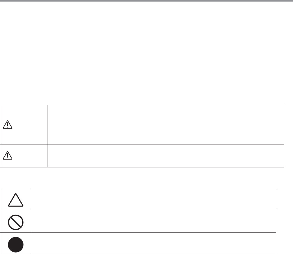
Explanation of Picture Symbols
Denotes an important warning or caution. Inside or near the symbol will
appear another symbol giving details.
Denotes a forbidden action. Inside or near the symbol will appear another
symbol giving details.
Denotes an action that you must take. Inside or near the symbol will
appear another symbol giving details.(Ex: Unplug power plug from outlet)
Ūŷ
!
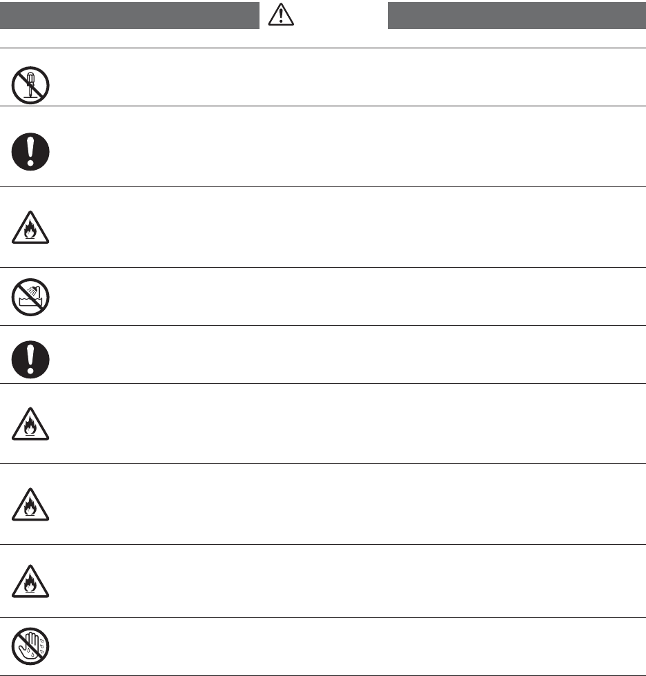
Warnig
Do not take apart, repair or modify the main unit.
This may cause fi re or electrocution.
When installing and using this product, make sure to follow all warnings and
directions from your computer manufacturer.
Be careful of igniting fi re.
If water or a foreign body enters into this unit, immediately unplug the AC adaptor
and stop using.
Continued use may cause fi re or electrocution.
Do not use this unit in wet or humid places, such as a bathroom.
It may cause a fi re or other trouble including malfunction.
Store main units, AC adaptors, and LAN cables out of the reach of children.
Touching them may result in injury and it is dangerous if they are dropped.
If any smoke or strange smells are emitted from the unit, immediately pull out the
AC adaptor and cease using it.
Continued use may cause fi re or electrocution.
Do not drop the unit, or expose the unit to a strong impact. If that happens,
immediately unplug the AC adaptor and stop using it.
Continued use may cause fi re or electrocution.
Make sure to periodically remove dust and dirt from the AC adaptor plug.
If dust is allowed to accumulate on the plug, moisture may cause poor insulation and
result in fi re.
Do not unplug the AC adaptor with wet hands.
This may cause electrocution.
ŷ
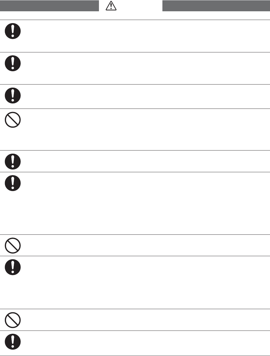
We are not responsible for any damage, malfunction or trouble, whether direct
or indirect, caused by the use of our product.Please be fully aware of this before
using our product.
This product has been designed for private or industrial use only. It is not for use
in situations where strict safety precautions are necessary such as in connection
with medical equipment, whether directly or indirectly.
This unit is not waterproof.
If the unit gets dirty, wipe it with a clean cloth dipped in alcohol.
Harmful gases or chemicals may cause corrosion and/or other danger to the
unit.Also, by coming in contact with hazardous substances, harm may occur to
the people handling the unit. Therefore, do not use in any environment that is
exposed to chemicals and harmful gases.
Make sure that the LAN cable and AC adaptor are inserted fully, so as not to cause an
improper connection.
Condensation may occur if the unit is moved from one environment to another
where the difference in temperature is great. Use the unit in an environment
where the ambient temperature is from 0 to 50Ɏ and the humidity is between
20% and 80ɓ RH (no condensation).
If you are using a Wireless LAN card, please follow all instructions included with
the card.
Please do not insert your fi ngers or any foreign objects into the connection jacks.
To prevent damage to the unit from static electricity, remove static electricity
from your body by touching metal around you (door knob, window frame) before
touching the unit.
Static electricity may cause not only damage to the unit, but may cause breaks in
or a loss of data.
Do not put anything on top of the AC adaptor.
This may cause overheating.
Also, when unplugging the LAN cable from the main unit, do not pull the cord, but hold
the connector to disconnect.
!
Caution
ŷŪ
Do not use or store the unit in places such as listed below:
Doing so may cause electrocution, fi re and/or other adverse effects to the device
and/or your computer.
- Areas exposed to direct sunlight
This will cause the inside of the device to become overheated and may cause fi re,
deformation, and/or other damage including malfunction.
- Areas prone to strong magnetic fi elds
This may cause damage including malfunction.
- Areas exposed to water leakage
This may cause electrocution or other damage including malfunction.
- Areas exposed to excessive vibration
This may cause injury, malfunction, damage or loss of proper electrical contact.
-Areas that are not fl at or level
This may cause the unit to fall and result in injury and / or damage.
-Areas near fi re or exposed to excessive heat
This may cause damage including malfunction and deformation.
-Areas prone to smoke, dust and dirt
This may cause damage including malfunction.
!
Wireless Regulations
This device complies with part 15 of the Federal Communications Commision (FCC)
rules. Operation is subject to the following conditions:
(1) This device may not cause harmful interference, and
(2) This device must accept any interference received, including interference that may
cause undesired operation.
Note:
This equipment has been tested and found to comply with the limits for a Class A digital
device, pursuant to part 15 of the FCC Rules. These limits are designed to provide reasonable
protection against harmful interference when the equipment is operated in a commercial
environment. This equipment generates, uses, and can radiate radio frequency energy and,
if not installed and used in accordance with the instruction manual, may cause harmful
interference to radio communications. Operation of this equipment in a residentional area
is likely to cause harmful interference in which case the user will be required to correct the
interference at his own expense.
Changes or modifi cations not expressly approved by the party responsible for
compliance could void the user's authority to operate the equipment.
This device complies with RSS-210 of the Industry Canada (IC). Operation is subject to the
following two conditions:
(1) this device may not cause interference, and (2) this device must accept any interference, including
interference that may cause undesired operation of the device.

ŷŪŪ
Contents
ɡNotices about this User's Manual --------------------------i
Software User's Agreement ---------------------ii
ɡEscape Clauses ----------------------------------------------- ii
ɡCopyright -------------------------------------------------------- ii
Safety Precautions and Instructions ---------- iii
ɡExplanation of Symbols ------------------------------------ iii
What is Web Wing WL RTR-5W ? ------------- 1
ɡExamples of Usage ------------------------------------------1
ɡBasic Functions -----------------------------------------------2
ɡBasic Functions of RTR-5W for Windows --------------3
Package Contents --------------------------------- 6
RTR-5W Part Names and Functions --------- 7
ɡPart Names -----------------------------------------------------7
Outline of Use -------------------------------------- 9
ɡBasic Operation -----------------------------------------------9
ɡSoftware Operations Table ------------------------------- 13
Getting the RTR-5W Ready to Use ----------15
ɡConnect the supplied AC adaptor ---------------------- 15
ɡConnect the supplied LAN cable ------------------------ 15
Communicating with the Data Logger -------16
ɡCommunicating with a Data Logger via Optical
Communication ------------------------------------------------- 16
ɡCommunicating with a Data Logger via Wireless
Communication ------------------------------------------------- 16
External Output -----------------------------------17
ɡConnecting the Signal Wire ------------------------------ 17
ɡRemoving an Input Signal Wire ------------------------- 17
Checking your Operating Environment ------18
ɡPC Operating Environment ------------------------------- 18
ɡUsing a LAN -------------------------------------------------- 18
ɡConnecting Directly to a PC ----------------------------- 18
ɡUsing a Wireless LAN ------------------------------------- 18
ɡUsing the Internet ------------------------------------------- 18
Connecting to a Network -----------------------19
ɡConnecting to a HUB for in-company Communication 19
ɡConnecting Directly to PC for Communication ------ 19
ɡConnecting to a Wireless LAN -------------------------- 20
Connecting to the Internet ----------------------21
ȺConnection Example Ȼ --------------------------------------- 21
Installation ------------------------------------------23
Using the Network Settings Utility ------------25
ɡHow to Open ------------------------------------------------- 25
ɡUsing Help ---------------------------------------------------- 25
ɡNetwork Settings Utility Functions ---------------------- 26
Network Initialization Settings -----------------27
Detailed Network Settings ----------------------29
ɡReceiving Settings ----------------------------------------- 29
ɡMaking Settings (Changes) ------------------------------ 30
Returning the Network Settings to the Factory
Default Settings -----------------------------------33
RTR-5W Clock Settings -------------------------34
ɡAutomatic Setting of the Clock -------------------------- 34
ɡMaking the Clock Settings Manually ------------------- 36
How to Operate RTR-5W for Windows -----37
ɡHow to Openȁ ---------------------------------------------- 37
ɡUsing Help ---------------------------------------------------- 37
ɡRTR-5W for Windows Functions ------------------------ 38
Remote Registration -----------------------------39
ɡCreate a Location ------------------------------------------- 39
ɡCreating Groups -------------------------------------------- 42
ɡRegistering a Remote Unit ------------------------------- 43
ɡSending Registration Info to an RTR-5W ------------ 45
ɡWireless Communication Test --------------------------- 46
Recording Settings -------------------------------47
Adjustment Function -----------------------------50
ɡ1-point / 2-point Adjustment ----------------------------- 50
ɡAdjustment Settings ---------------------------------------- 50
Downloading Data --------------------------------51
ɡWhen using Wireless Communication ---------------- 51
ɡWhen using Optical Communication ------------------ 52
Operating the Temp / Humidity Graph -------53
ɡHow to Openȁ ---------------------------------------------- 53
ɡUsing Help ---------------------------------------------------- 53
ɡTemperature / Humidity Graph Display Names and
Functions --------------------------------------------------------- 54
ɡData List Display Part Names and Functions -------- 56
Making Changes to the Graph Display ------57
ɡChanging Colors of Data Display Area ---------------- 57
ɡSelected Channels ON / OFF --------------------------- 57
ɡSet High, Low, Average Calculation Range ---------- 57
ɡEditing Recording Conditions ---------------------------- 58
ɡRe-order Channel Data ----------------------------------- 58
ɡErase Selected Channel Data --------------------------- 60
ɡShift Unit (Ɏ / ȌF) --------------------------------------- 60
ŷŪŪŪ
ɡChange Graph Colors ------------------------------------- 60
ɡCopy Display to Clipboard -------------------------------- 61
Operating the Graph Display ------------------62
ɡReturning to Original Size -------------------------------- 62
ɡZooming In and Out ---------------------------------------- 62
ɡMoving the A/B Cursors Right and Left -------------- 62
ɡMoving Right and Left on the Graph ------------------- 62
ɡMoving Up and Down on the Graph ------------------- 62
ɡVertical Axis Settings -------------------------------------- 62
How to operate the Multi-scale Graph -------63
ɡHow to Openȁ ---------------------------------------------- 63
ɡUsing Help ---------------------------------------------------- 63
ɡMulti-scale Graph Display Names and Functions -- 64
ɡData List Display Part Names and Functions -------- 66
Making Changes to the Graph Display ------67
ɡSelected Channels ON / OFF -------------------------- 67
ɡScale Channels ON / OFF ------------------------------- 67
ɡSet High, Low, Average Calculation Range ---------- 68
ɡEditing Recording Conditions ---------------------------- 69
ɡRe-order Channel Data ----------------------------------- 70
ɡMerge Channel Data -------------------------------------- 71
ɡErase Selected Channel Data --------------------------- 72
ɡSet Vertical Axis Display Range ------------------------ 73
ɡScale / Unit Conversion ----------------------------------- 74
ɡChange Graph Colors ------------------------------------- 75
Operating the Graph Display ------------------77
ɡReturning to Original Size -------------------------------- 77
ɡZoom out step by step ------------------------------------- 77
How to Operate the Event Viewer ------------78
ɡHow to Open ------------------------------------------------- 78
ɡUsing Help ---------------------------------------------------- 78
ɡEvent Viewer Display Part Names and Functions -- 79
Change the Event Viewer Method of Display 80
ɡShift Display -------------------------------------------------- 80
ɡShift Descending / Ascending --------------------------- 80
ɡFile Info -------------------------------------------------------- 81
Print Preview and Print --------------------------82
Saving Recorded Data --------------------------83
Creating Text File ---------------------------------85
ȺFor Event ViewerȻ -------------------------------------------- 86
Opening a Saved File ----------------------------87
Auto-Download Settings ------------------------88
Warning Monitoring ------------------------------90
How to use the RTR-5W Web Viewer -------94
ɡOpening the RTR-5W Web Viewer --------------------- 94
ɡRTR-5W Web Viewer Functions ------------------------ 95
Current Readings Monitor ----------------------96
Graph ------------------------------------------------97
Viewing Current Readings via Mobile Phone 98
Checking and Making Changes to Computer
Network Settings ----------------------------------99
Downloading JRE ------------------------------ 102
Re-installing -------------------------------------- 105
Troubleshooting --------------------------------- 106
ɡNetwork Settings Utility --------------------------------- 106
Q&A about RTR-5W --------------------------- 108
ɡQ&A about RTR-5W ------------------------------------- 108
ɡQ&A about Web Server Functions ------------------ 109
ɡQ&A about Viewing the Web Site --------------------- 110
ɡQ&A about Networks ------------------------------------ 110
ɡQ&A about the Internet ---------------------------------- 113
Specifi cations ------------------------------------ 116
ɡWeb Wing WL RTR-5W -------------------------------- 116
ɡPC Operating Environment ----------------------------- 116
ɡRTR-5W for Windows® ---------------------------------- 116
ɡAbout the RTR-5W Series Web Viewer ------------- 117
Options -------------------------------------------- 118
ɡAC adapterȪfor RTR-5Wȫ ----------------------------- 118
ɡWall Attachment Unit Ȫfor RTR-5Wȫ ----------------- 118
ɡTemperature SensorsȪFor TR-52/RTR-52ȫ
---- 118
ɡTemp / Humidity SensorȪFor RTR-53ȫ
--------- 120
ɡInput CablesȪFor RVR-52Aȫ
------------------- 120
ɡSensor Extension CablesȪFor RTR-52ȫ unit:
millimeters --------------------------------------- 121
ɡPowerȪFor RTR-5/RVR-5ȫ
--------------------- 121
ɡPowerȪFor TR-5/RTR-5/RVR-5ȫ --------------------- 122
ɡWall AttachmentȪFor TR-5/RTR-5/RVR-5ȫ
----- 123
IJ
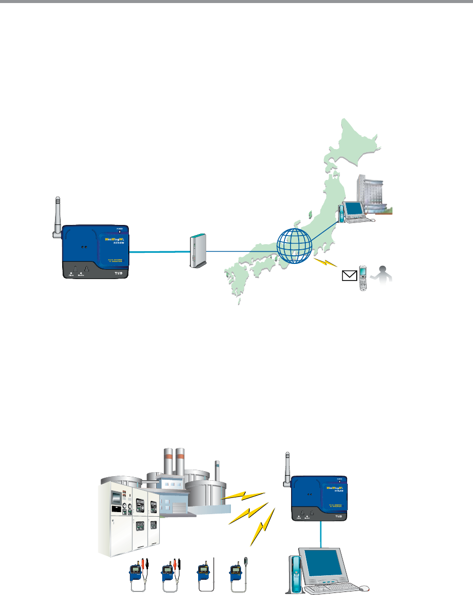
What is Web Wing WL RTR-5W ?
The RTR-5W not only serves as a base station for the wireless downloading of recorded
data from our compact waterproof Wireless Communication RTR-5 Series Data Loggers,
but, moreover, the [Web Wing WL RTR-5W] serves as a network base station that allows
you to monitor and view current readings and gather recorded data via LAN or Internet
connection.
ŐŧŧŪŤŦ
2̜
.@/: ̥
ABC
3̯
DEF
4
̹
GHI
5̈́
JKL
6
͉
MNO
7
͘
PQRS
8͞
TUV
9
ͣ
WXYZ
:
ল
ζȜ ικ
1
ͩͬͭ
ܱ
·ςͺ
HILD
ഩ࡙
㧨㧪
ŎŢŪŭ
œŕœĮĶŘ
ōłŏ
œŰŶŵŦų ŊůŵŦųůŦŵ
ɡExamples of Usage
-Recording measurements taken from various measuring instruments such as fl ow meters,
power meters, and analyzers.
-Data recording of moving objects and rotating objects on a production line.
-Temperature an humidity management in high humidity environments such as brewing and crop
cultivation.
-Measurement in places where wiring is diffi cult or impossible.
*The RTR-5W is designed solely for network communication.It does not include any RS-232 or USB communication interface. To make
use of this product you must connect it to a network.Moreover, in order to use this product via the Internet you will need other devices
(such as a router) and must fi rst make necessary arrangements with a provider for a line and get a fi xed IP address, domain, etc....
*When making settings in an RTR-5W without any settings already made (when purchased or after resetting), it is necessary to carry out
these settings using a wired LAN connection. After having made all the necessary settings via the wired connection, it is possible to
use a wireless LAN connection.
ij
ɡBasic Functions
Gathering and Managing Remote Unit Data via a Network
The RTR-5W is able to gather via wireless communication the measured and recorded data from
any RTR-5x Series Data Logger and using a Local Area Network (LAN) or Internet connection
makes it possible to view current readings and / or download the gathered recorded data.
With the internal WEB Server, use a browser to check current readings and view in
simple graph form
Because the RTR-5W is designed with a built-in WEB server, it can be accessed directly from
your Internet browser.Via the browser you can check the current readings of any Remote Unit
that has been registered and view the recorded data in the Remote in a simplifi ed graph form.
Connect to a Wireless LAN via CF Card
The RTR-5W is designed with a CF card slot.By inserting a wireless LAN card in this CF card
slot, it is possible to connect to a Wireless LAN; releasing you from the burden of cables and
wiring.
*For information and updates concerning which wireless LAN cards can be used please see our
Homepage.
Internet Connection allows for Public Access to Data
The built-in WEB server gives you the option of putting your data on the Internet for public
access.
Also the by using the Internet connection you can escape the boundaries of the Local Area
Network and gain the freedom to manage and collect data from anywhere where the Internet is
available; a low-cost alternative to having to be in the local area.
View Current Readings via Cell Phone
It is also possible to use your cell phone browser to view current readings.
Set Upper / Lower Limits and Send Warning Report E-Mail
By making upper and lower limit settings for the RTR-5W, when one of the set upper or lower
limits has been exceeded, a warning report mail can be sent via e-mail. !
*To make use of the warning report e-mail send function, it is necessary to be create an environment in
order to connect to the Internet or to an in-company (in-house) SMTP/POP server.
When a warning occurs it is possible to use contact output
When a set upper or lower limit has been exceeded, it is possible not only to send a warning
report via e-mail, but it is also possible to use the provided contact output on the main unit to
issue a warning within a structured warning system.
Ĵ
ɡBasic Functions of RTR-5W for Windows
The software is made up of the following 5 applications: [Network Settings Utility], [RTR-5W
for Windows], [Temperature /Humidity Graph], [Multi-Scale Graph] and [Event Viewer]. Also,
by using your web browser to access RTR-5W, it is possible to view data via the Internet.
*Only compatible with Internet Explorer Ver.6 or higher using Windows 2000 / XP
ȺNetwork Settings UtilityȻ
Make the necessary network settings for RTR-5W.
Network Initialization Settings
Settings for helping to connect a RTR-5W to a network.
Detailed Network Settings
Make detailed Network settings here.
ȺRTR-5W for WindowsȻ
Make all necessary settings in order to communicate with RTR-51/52/53ȂRVR-52AA Data
Loggers via the RTR-5W Base Station.For each RTR-5W it is possible to create one tree,
and in that tree register Remote Units for communication.
Remote Registration
Register any logger in the RTR-5 Series as a Remote Unit; also possible to register in Groups
for easy management.
Recording Settings
By setting the recording interval, the recording start time and the recording mode, recording will
begin at the set date and time.
Downloading Recorded Data
Download recorded data from the RTR-5W to a computer and create fi les.
Also, by making Auto-Download settings, it is possible to gather from Remote Units at a set
interval of time or at a set time of day.
Warning Monitoring
If a measurement exceeds the set limit, a notifi cation can be sent via e-mail from the RTR-5W
to your computer or cellular phone.Also, because there is a built-in external output terminal, it
is possible to connect to an external device, such an alarm or light, so that a notifi cation of a
warning can be seen or heard onsite.
Gathering Current Data
Gather and view current measurement readings from the selected Remote Unit(s).
Transfer Data
The RTR-5W retrieves and stores data at a set regular interval.This stored data is transferred for
display.
ĵ
ȺTemperature / Humidity GraphȻ/ȺMulti-Scale GraphȻ
Temperature and Humidity are displayed in the Temperature and Humidity Graph In the
Multi-Scale Graph, voltage, pulse, temperature and humidity data can be viewed in Graph
form.
In Multi-Scale Graph, it is possible to make settings for scale and unit of measurement to
match the type of date being downloaded.
View Graphs and Print
It is possible to view the downloaded data as a list and print.
ɡView 8 channels of data in 1 display
Up to 8 channels of recorded data can be viewed in the same graph at one time.
ɡEasy zoom in and out with mouse
By selecting a range with your mouse you can easily zoom in and out on data.
ɡCalculate and view the highest, lowest and average readings for a desired range
In the Graph, for each channel it is possible to designate a desired range from which the highest, lowest
and average readings will be calculated and displayed.
ɡGraph Printing
It is possible to easily print in color the Graph as it is being displayed.
View and Print Data List
You can view the data displayed in the graph window as a list and then choose to print.
ɡView in Easy to Distinguish Colors
In the data list, the highest value will appear in red, the lowest in blue, and the average in pink.
ɡPrinting the Data List
It is possible to print the entire list as displayed or to select pages for printing.
Creating Text File
It is possible to convert the data for a specifi ed range (time period) to common text fi le format
(CSV type format), so that it can be exported to spreadsheet software such as Excel or Lotus.
Ķ
ȺEvent ViewerȻ
View and print Event data recorded with the RVR-52A Data Logger.
View List
Up to 64 channels of downloaded data can be viewed in one list.
Print Preview and Print
Printing can be carried out after checking the preview window.
Creating Text File
It is possible to convert the data for a specifi ed range (time period) to common text fi le format
(CSV type format), so that it can be exported to spreadsheet software such as Excel or Lotus.
ȺRTR-5W Web ViewerȻ
Use your browser to monitor current readings and view data graphs.
Monitor Current Readings
The RTR-5W communicates with Remote Units at a set regular interval and then stores the
gathered readings. The most recent measurement will be displayed.
It is also possible to view via a cell phone browser.
Graph
The graph displayed in the browser will be the same graph that is shown upon opening [Transfer
Data] in [RTR-5W for Windows].
ķ
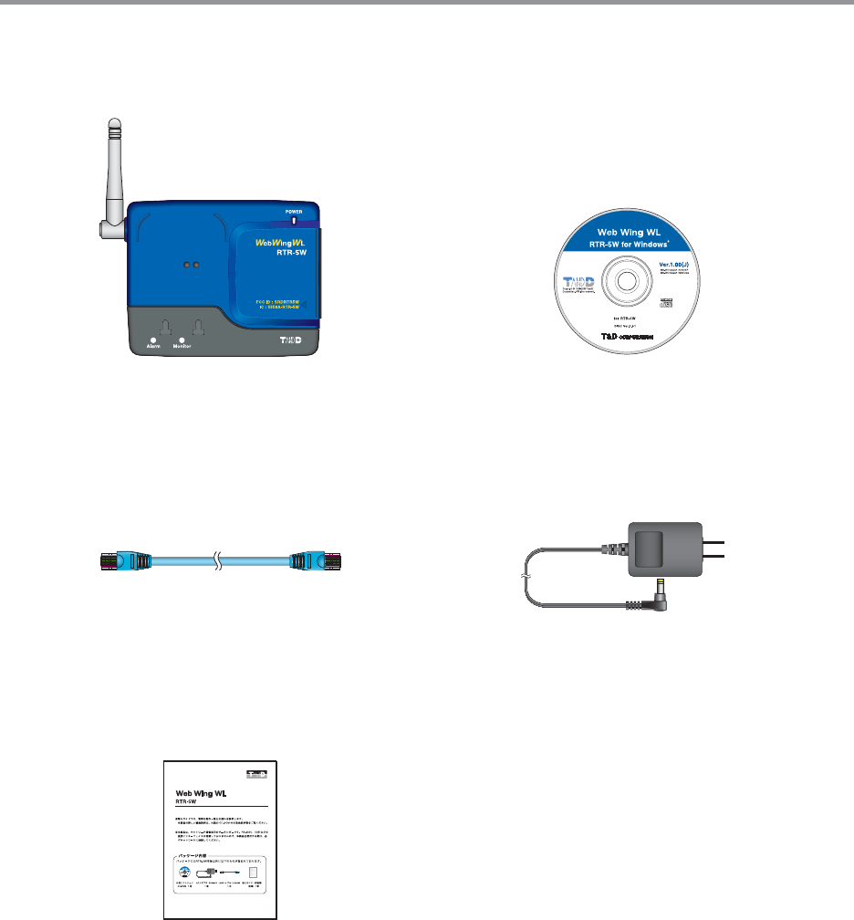
Package Contents
The following items are included in the package:
AC Adaptor AD-0605 x 1
#!54)/.
RISK OF ELECTRIC SHOCK
DRY LOCATION USE ONLY.
SHOCK HAZARD NON-
SERVICEABLE PARTS INSIDE.
LAN Cable LN-20W x 1
Introductory Guide and
Warranty x 1
Software CD-ROM x 1
Web Wing WL RTR-5W
x 1 unit
൵ව΄ͼΡ
./)45!#
KCOHS CIRTCELE FO KSIR
.Y
LNO
E
S
U
N
OI
TACOL
Y
RD
-NON DRAZAH KCOHS
.EDI
S
NI
S
TR
A
P
EL
BA
E
CI
VR
ES
ĸ
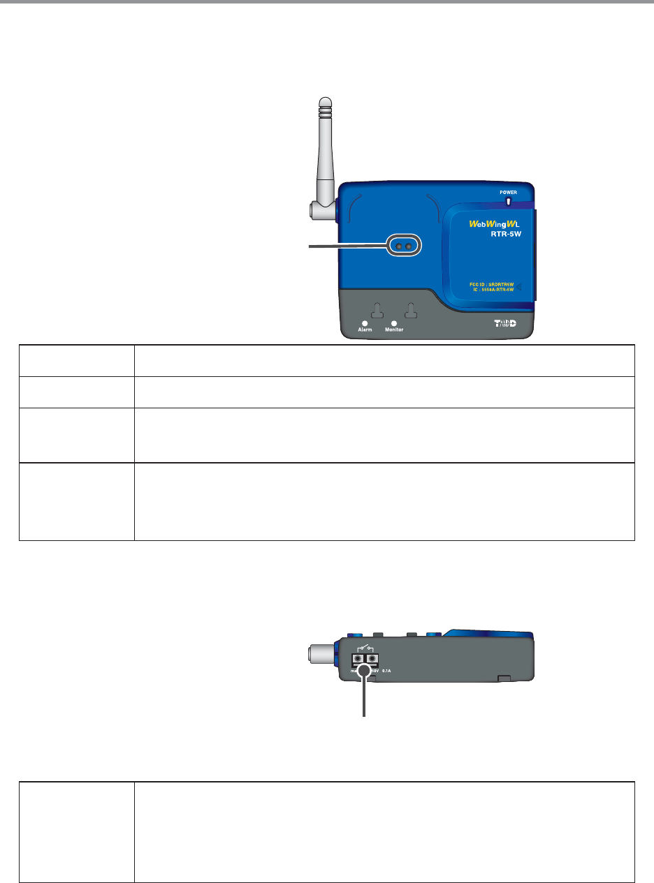
RTR-5W Part Names and Functions
ɡPart Names
ȬFRONTȭ
Optical Communication Area
POWER LED While the power is ON, the lamp will be on.
Alarm LED When a warning occurs, the lamp will blink.
Monitor LED While wireless communication is occurring with a Remote Unit, the
lamp will blink.
Optical
ommunication
Area
When you wish to communicate directly, not by wireless, with a
data logger (Remote Unit), it is necessary to place the logger
(Remote Unit) face down on this area for communication to occur.
ȬBottomȭ
External Output Terminal
External
Output
Terminal
Connect to an alarm buzzer or light to notify locally of the
occurrence of a warning. [Conditions for Output to be switched
ON]It switches to ON when a warning is received from at least one
Remote Unit.
Ĺ
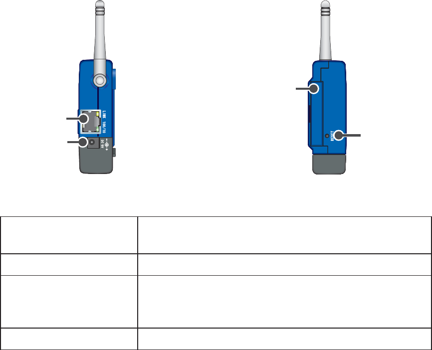
ȬRIGHT SIDEȭȬLEFT SIDEȭ
Reset Button
CF interface slot
AC Adaptor
Jack
Ethernet Jack
Ethernet Jack 10Base-T/100Base-TX Ethernet ConnectorConnect with
LAN Cable
AC Adaptor Jack Connect using the supplied AC adaptor
CF Interface Slot
Insert a Wireless LAN Card ɦ1
NOTE: Do not insert or try to connect anything other than a
CF communication card
RESET Button Press to return to the factory default settings
*1ȇFor information and updates concerning which wireless LAN cards can be used please see our
Homepage.
ĺ
Outline of Use
ɡBasic Operation
ȺGetting ReadyȻ
1.Prepare the Data Loggers you wish to use as Remote Units.
Get the units ready for measuring by connecting the proper sensors and installing the proper
batteries.
2.Getting the RTR-5W Ready to Use
Get the unit ready for communication by connecting the network cable and AC adaptor.
3.Checking your Operating Environment
You also need to check your computer and network setup and be sure to prepare any
necessary devices like routers to enable connection to your access point
4.Connecting to a Network
Connect the RTR-5W to the desired network.
See p. 19-20 for connection examples of how to connect directly to your computer or use a
router.
*Even if you are planning to use a wireless LAN, it is necessary to make the initial settings via
a wired connection.
5.Install [RTR-5W for Windows]
To enable set up, install the supplied software [RTR-5W for Windows] into your computer.
By installing RTR-5W, all of the following applications will be installed: [RTR-5W for Windows]
for setting up Remote Units, making recording settings and other operational settings, [Network
Settings Utility] for making network settings, and [Temperature /Humidity Graph], [Multi-Scale
Graph], [Event Viewer] for viewing various types of recorded data.

IJı
ȺInitialization SettingsȻ
1.Network Initialization Settings Ȥfrom the Network Settings Utility
To connect to a network, it is necessary to enter an IP address and Subnet Mask that are
appropriate for your network. Under Network Initialization Settings make the appropriate
settings for your ȨIP addressȩ and ȨSubnet Maskȩ. More detailed settings can be made
in [Detailed Network Settings]
2.Remote Unit RegistrationȤ from RTR-5W for Windows
In order to carry out wireless communication between an RTR-5W base station and a Remote
Unit, please register Data Loggers as Remote Units as follows
1. Create a Location
2. Create Group(s)
3. Register Remote Unit(s)
Up to 64 Remote Units can be registered to one Location.
ȺBasic OperationsȻ
1. Recording SettingsȤ from RTR-5W for Windows
By setting the Recording Interval, the Recording Start Date / Time and the Recording Mode,
recording will begin at the set date and time.
2. Download Data Ȥfrom RTR-5W for Windows
Data recorded in the Remote Unit will be downloaded and saved in your computer as a data fi le.
Downloaded temperature and humidity data can be viewed in [Temp /Humidity Graph],
downloaded Voltage, Pulse and Temp / Humidity data can be viewed in [Multi-scale Graph] and
downloaded Event data can be viewed using [Event Viewer].

IJIJ
ȺGraph DisplayȻ
Temp / Humidity Graph
Temperature and Humidity data can be displayed in the same Temperature and Humidity Graph
(Up to 8 channels of data)
You can view the data displayed in the graph window as a list and also choose to print. It is also
possible to convert the data to common text fi le format (CSV type format).
Multi-scale Graph
In the Multi-Scale Graph, voltage, pulse, temperature and humidity data can be viewed in the
same Graph. (Up to 8 channels of data)
You can view the data displayed in the graph window as a list also choose to print. It is also
possible to convert the data to common text fi le format (CSV type format).
Event Viewer
The Event Viewer allows you to add and view up to 64 channels of downloaded Event Time data
recorded with the RVR-52A.
Select the channels of data you wish to print from the channels displayed in the Event Viewer;
view them in the Print Preview, and Print(Up to 4 channels can be selected at one time)
It is also possible to convert the data to common text fi le format (CSV type format).

IJij
ȺOther FunctionsȻ
Warning Monitoring SettingsȤ from RTR-5W for Windows
Monitoring at each Location for warnings is carried out and if any of the gathered data exceeds
the set limit, a notifi cation can be sent via e-mail to your computer or cellular phone.Also,
because there is a built-in external output terminal, it is possible to connect to an external device,
such an alarm or light, so that a notifi cation of a warning can be seen or heard onsite.
If the RTR-5W is not connected to the Internet, warning report e-mail cannot be sent.
Auto Download Settings Ȥfrom RTR-5W for Windows
The downloading of data can be set to be automatically carried out at a specifi ed time or at a set
interval of time.
For Auto download to occur at a set time, it is necessary for RTR-5W for Windows to be open.
Gather Current DataȤfrom RTR-5W for Windows
RTR-5W communicates with Remote Units to gather and display the current measurement
readings.Also, by setting a communication interval, the current readings will be continuously
gathered and displayed at that interval.
If you are using RVR-52A to record Pulse Data, the current reading will be displayed as the
average of recorded readings during the set recording interval. If you are recording the time of
an Event, the current reading will show HI or LO (Rising Edge or Falling Edge.)
Transfer DataȤ from RTR-5W for Windows
The RTR-5W retrieves and stores data at a regular interval set in [Location (RTR-5W)
Properties].This stored data is transferred and displayed for each Remote Unit.
* Event Data recorded with RVR-52A cannot be viewed in this manner.
Monitor Current ReadingsȤRTR-5W Web Viewer
The RTR-5W retrieves and stores data at a regular interval set in [Location (RTR-5W)
Properties].The most recent measurement reading(s) can be viewed in the browser.
GraphȤRTR-5W Web Viewer
The graph displayed in the browser will be the same graph that is shown upon opening [Transfer
Data] in [RTR-5W for Windows]
IJĴ
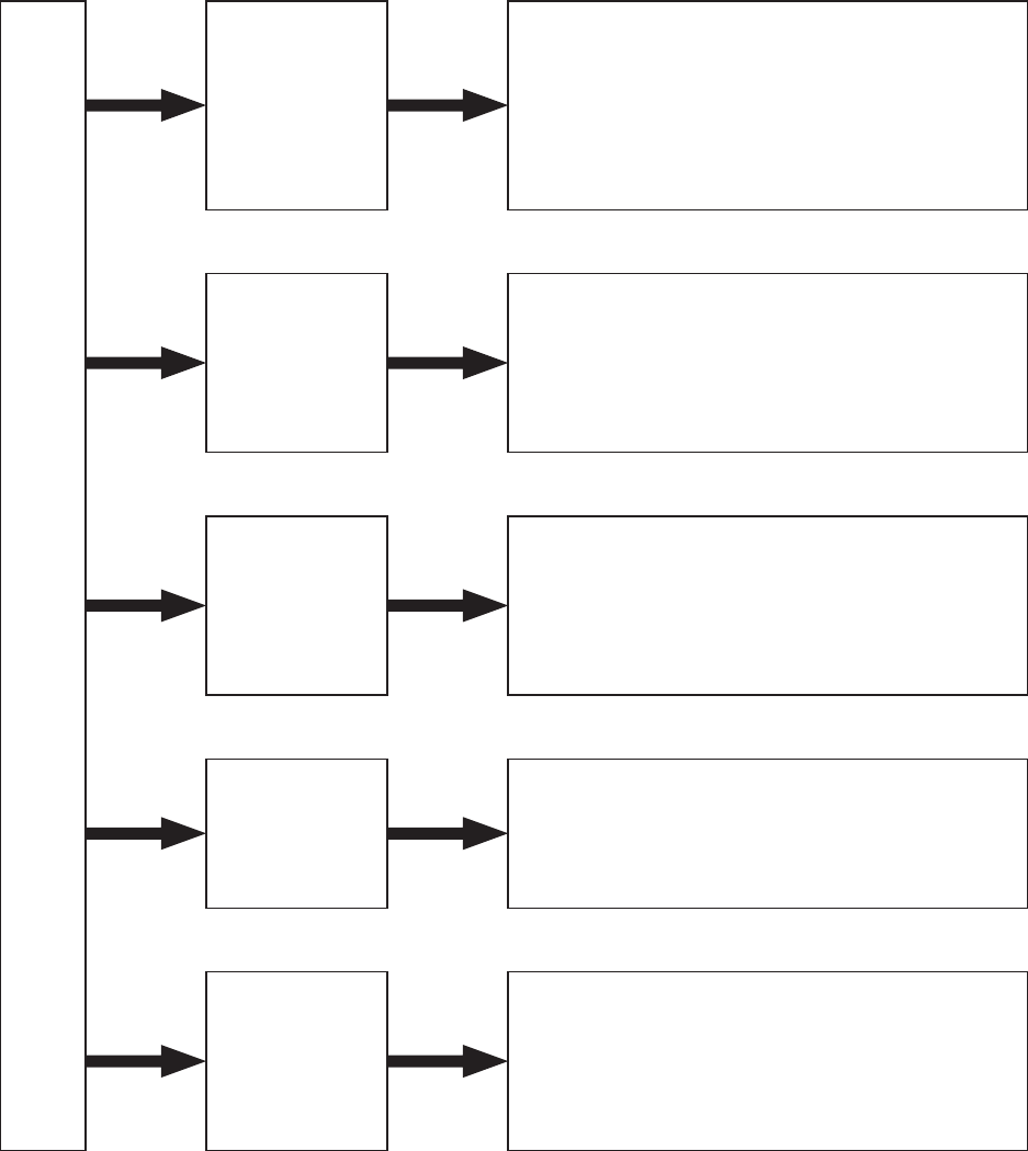
ɡSoftware Operations Table
ȺRTR-5W for WindowsȻ
RTR-5W for Windows
ȶFileȷ
menu
Temp/Humidity Graph
Multi-scale Graph
Event Viewer
Text Data Output Settings
Read Data Collector Registration Info File
Output Registration Info File for Data Collector
ȶViewȷ
menu
Expand to Whole Tree
Programmed Auto Download
View Log
Store in Task Tray
Display Format Settings
ȶRegistration /
Administrationȷ
menu
Create Locations / Properties
Create Groups / Properties
Remote Unit Registration / Properties /
Initialization
Delete from Tree
ȶSettingȷ
menu
Start / Stop Recording
Start / Stop Warning
Send Group / Remote Info
Script Update
ȶDataȷ
menu
Download Data (Wireless)
Download Data (Optical Communication)
Gather Current DataȤ
Transfer DataȤ
View Remote Unit Battery Level
IJĵ
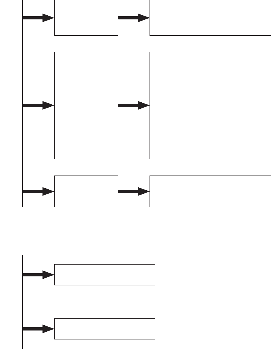
ȺNetwork Settings UtilityȻ
Network Settings Utility
Network
Initialization
Settings
IP Address
Subnet Mask
Network
Detailed Settings
Login ID
Password
DNS
SNTP
SMTP Mail Server
IP Block
Wireless LAN
Port Number
Time Difference
Rebooting the Communication Functions
(Restarting the System)
ȶMenuȷ
Menu
Login History – ON / OFF
Clear Login History
Communication Time Settings
ȺRTR-5W Web ViewerȻ
Web Viewer
Monitor Current Readings
Graph
IJĶ
Getting the RTR-5W Ready to Use
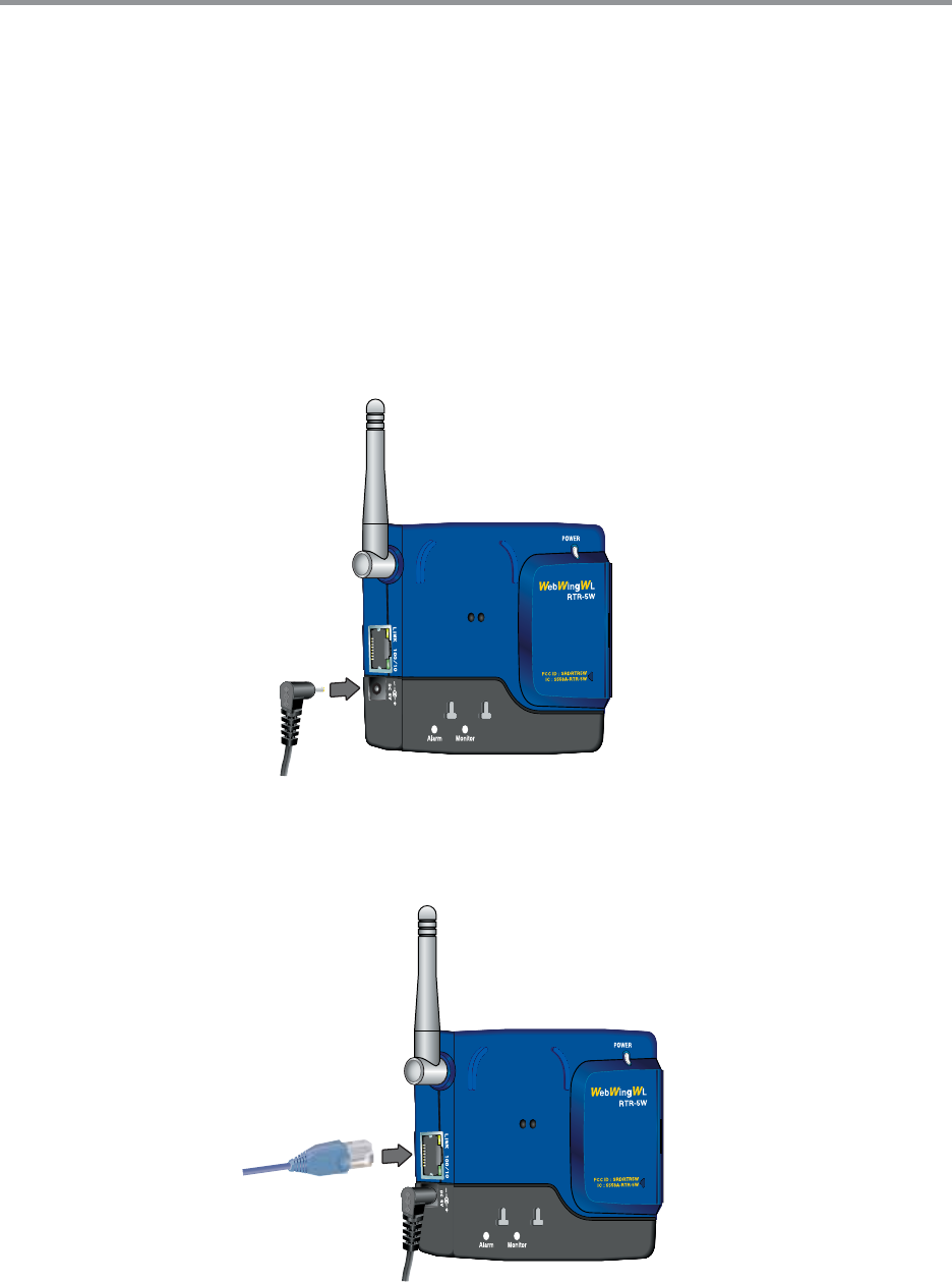
ɡConnect the supplied AC adaptor
*To ensure a proper connection make sure that the plug is completely inserted
NOTE:
- Do not use an AC adaptor other than the one that is supplied with the product. Doing so may cause
fi re or other trouble.
- Insert the AC adaptor plug into an AC 100V socket. Inserting the plug into a socket with different
voltage may cause fi re or other trouble.
- Do not insert or pull out the AC adaptor plug with wet hands or if there are water drops on the plug; it
may cause electrocution.
ɡConnect the supplied LAN cable
* To ensure a proper connection make sure that the connector is completely inserted.
IJķ
Communicating with the Data Logger
It is possible to communicate between an RTR-5W base station and Data Loggers
RTR-51/52/53ȆRVR-52A by two methods: [Wireless Communication] and [Optical
Communication].
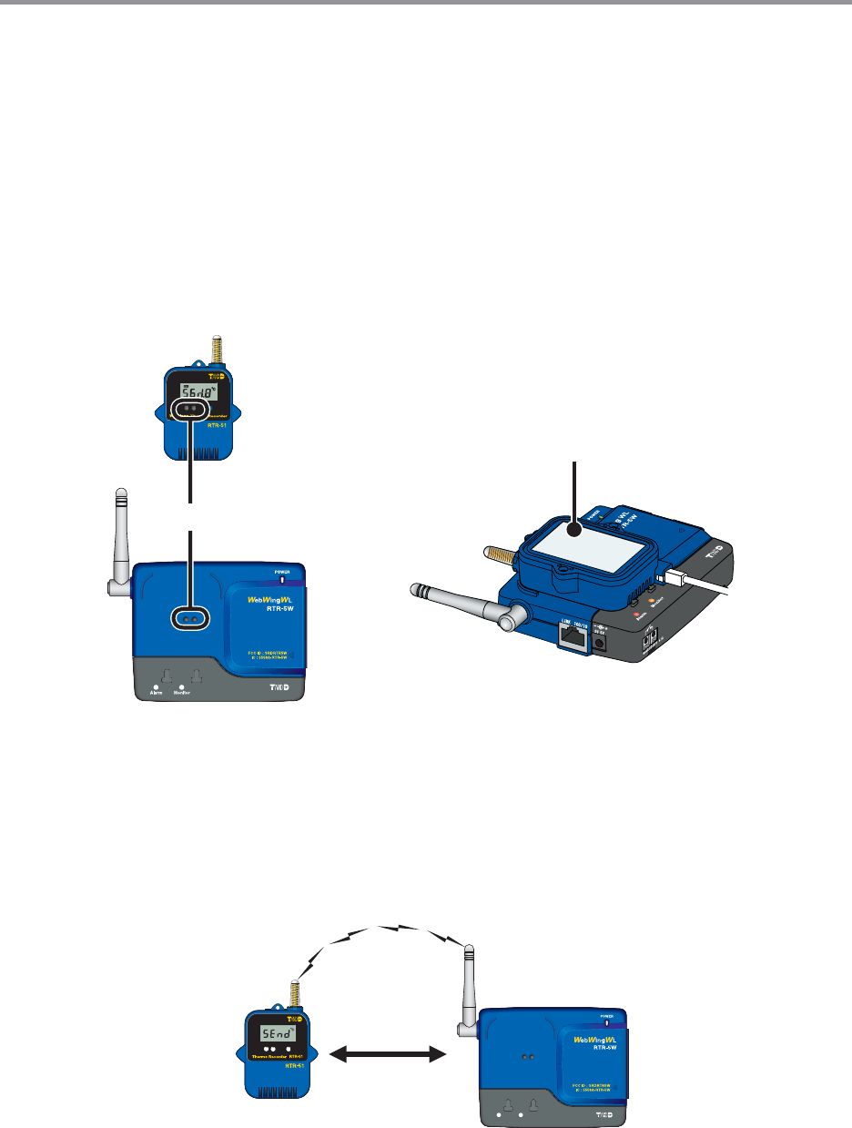
ɡCommunicating with a Data Logger via Optical Communication
Optical communication can be carried out by placing an RTR-51/52/53 or RVR-52A Data Logger
face down on the RTR-5W so that the optical communication areas meet.
*To make measuring mode changes in an RVR-52A, use via optical communication when registering a
Remote Unit.
Optical Communication Area
Place a Data Logger face down
on the RTR-5W
ɡCommunicating with a Data Logger via Wireless Communication
Communication is carried out with the RTR-51/52/53ȆRVR-52A Data Loggers via special short
wave wireless communication
In order to carry out Wireless Communication, use the supplied software [RTR-5W for Windows]
to register the Data Loggers as Remote Units of the RTR-5W Base Station.
7ITHINM
*The wireless communication range, if unobstructed and direct, is about 100 meters [330 ft].
IJĸ
External Output
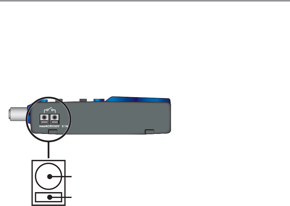
ɡConnecting the Signal Wire
1.
Prepare a ϫ0.5 ȡ0.9 single type wire and remove the covering to about 10mm from
the tip.
2.
Using a screwdriver or other such tool, while pressing down on the terminal button <B>
at the back of the unit, insert the wire into the hole <A>.
=A?
=B?
ȴEnlarged view of Wire
Connection Terminal ȵ
ɟExternal Output : With Warning ON
Voltage when OFF: AC/DC less than 50V
Current when ON: less than 0.1A
Resistance when ON: 35 Ϯ
ɟUseable Wires
Compatible Wires: Single wire: ϫ1.0(AWG18) / Twisted wire: 0.75mm2
Useable Wires Single wireȤϫ 0.4 ȡϫ 1.0(AWG26 ȡ18)
Twisted wireȤ0.3mm2 ȡ0.75mm2(AWG22 ȡ20)
Cable core diameterȤϫ 0.18
Standard Stripping Length 0.39in
Compatible Connector Tool: Screwdriver (Shaft: ϫ0.3 / Blade Tip Width: 2.6)
ɡRemoving an Input Signal Wire
If you wish to remove an input signal wire, press down on the <B> button with a screwdriver and
pull out the wire.
NOTE:
Please be careful when pulling out the wire.
IJĹ
Checking your Operating Environment
To properly use the logger, the following operational environment is necessary.
ɡPC Operating Environment
OS OS Microsoft Windows 2000
Microsoft Windows
*For installation, it is necessary to have Administrator (Computer Administrator) rights.
PC ȟCPU A Stable Windows Operating Environment
LAN TCP/IP Communication Possible
Memory Enough memory to stably operate Windows
Hard Disk More than 10 MB of free space (Data will need more space)
Monitor SVGA (higher than 800×600 recommended) more than 256 colors
LAN 100BASE-TX or 10BASE-T
Twisted pair cable confi rming to Category 5ȪSTP/UTPȫ
Web Browser Internet Explorer 6.0 or higher
ɡUsing a LAN
Connect the provided LAN cable to the HUB that is connected to your computer.
ɡConnecting Directly to a PC
Connect the RTR-5W to your computer with a LAN cross cable.
*LAN cross (reverse) cables are not included with the product. Please purchase separately.
ɡUsing a Wireless LAN
Please use a Wireless LAN card and a Wireless LAN access point (Combined Wireless LAN
and Hub OK).
ɡUsing the Internet
In order to connect to the Internet, you must fi rst make arrangements with a provider for a line.
It may also be necessary to get an IP address or domain and make domain name server and
other settings.
For more details about various settings, it is best, if present, to contact the network administrator.
To get more details about your Internet connection and setup, please contact your provider.
IJĺ
Connecting to a Network
The following are some ways to connect an RTR-5W to a network. Please select the
connection method that suits your network environment.
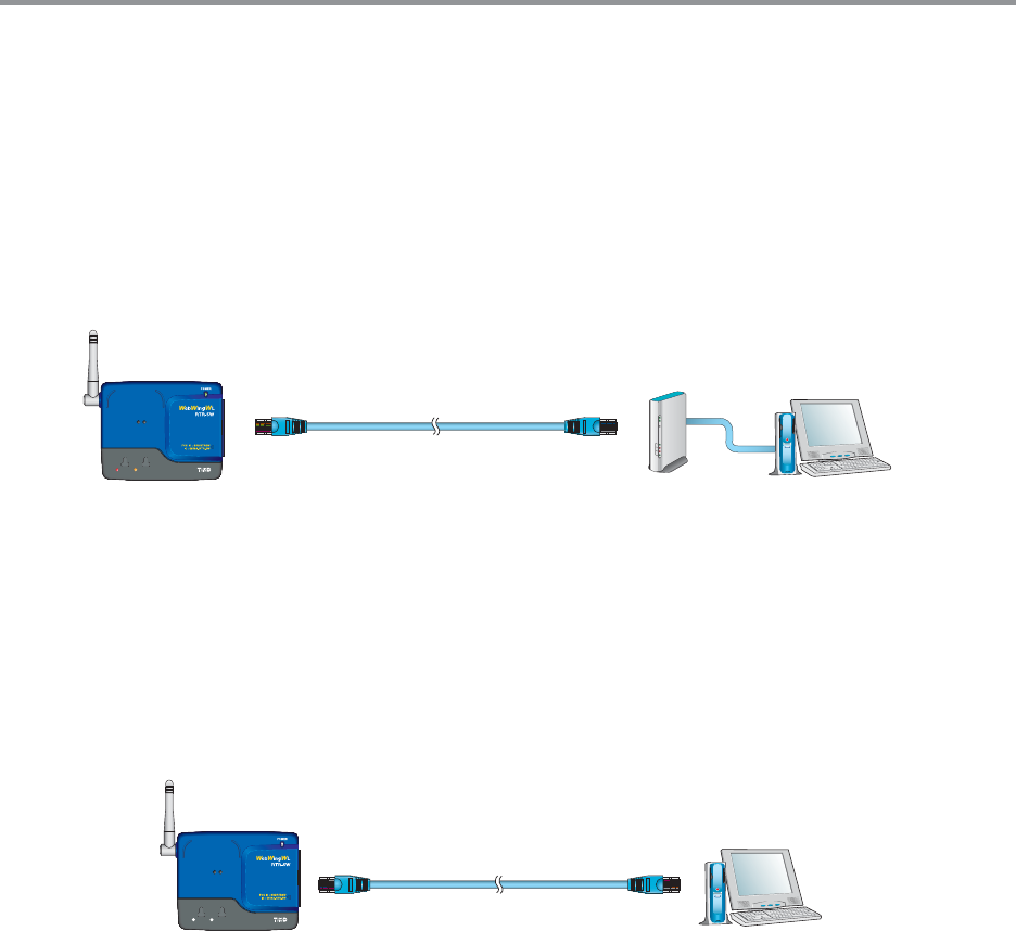
ɡConnecting to a HUB for in-company Communication
*To ensure a proper connection make sure that the plug is completely inserted
Connection Example
,!.CABLE
㧔,.7(5" 0#
㧔㧕
2427
㧔㧕
ɡConnecting Directly to PC for Communication
Do not use the supplied cable; please purchase a cross LAN cable separately.
*To ensure a proper connection make sure that the plug is completely inserted
Connection Example
,!.CROSSCABLE
0#
㧔㧕
2427
㧔㧕
ijı
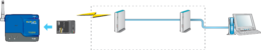
ɡConnecting to a Wireless LAN
By inserting a Wireless LAN card into the RTR-5W, it is possible to carry out communication in
places where LAN wiring is diffi cult or troublesome.
*To ensure a proper connection make sure that the plug is completely inserted
NOTE:
- Before you insert or take out the LAN card, make sure that the AC adaptor is unplugged.
- For information and updates concerning which wireless LAN cards can be used please see our
Homepage.
Connection Example
7IRELESS
,!.CARD
7IRELESS,!.
!CCESS0OINT 0#
㧔㧕
(5"
2427
ijIJ
Connecting to the Internet
In order to connect the RTR-5W to the Internet you must fi rst set up an Internet connection
environment by making arrangements with a provider for a line and get a global IP address
and domain. Also, if necessary, make all domain name server and / or router settings.
For more details about various settings, it is best, if present, to contact the network
administrator. To get more details about a global IP address and domain, please contact
your provider.
The following are examples of connection methods. Please select the connection method
that suits your network environment.
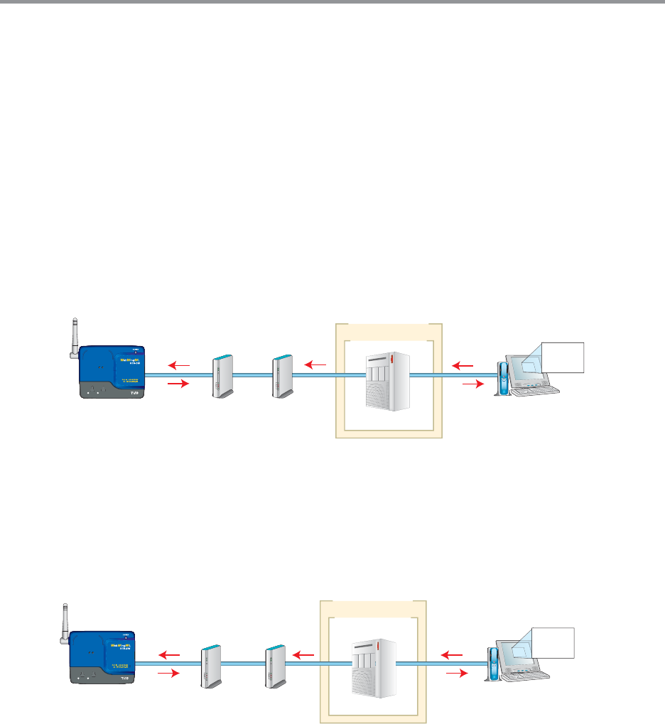
ȺConnection Example Ȼ
ɡUsing the RTR-5W on the Internet
).4%2.%4
0ROVIDER
2OUTER -ODEM
Ԙ
ԙ
HTTP
ԚԚ
2427
㧔㧕
0#
ӱIn order to access the RTR-5W from your browser, enter the Global IP address that has been assigned to the
RTR-5W in your browser’s URL bar following [http://]
ӲThe RTR-5W will be called via a router or the Internet provider .
ӳThe RTR-5W which received the access request will return data to the computer which sent the access request.
ɡUsing a Domain Name (ex: rtr-5w.net)
).4%2.%4
0ROVIDER
-ODEM2OUTER
2427
㧔㧕$.33ERVER
Ԙԙ
HTTPRTRWNET
0#
ԚԚ
ӱIn order to access the RTR-5W from your browser, enter the Domain Name (Ex rtr-5w.net)that has been
assigned to the RTR-5W in your browser’s URL bar following [http://].
ӲThe Domain Name that was entered in the URL bar is converted by the DNS server into an IP address and the
RTR-5W is called.
ӳThe RTR-5W which received the access request will return data to the computer which sent the access request.