Tantalus Systems N900 NC-90 NETWORK CONTROLLER User Manual NC 900 UserManual
Tantalus Systems Corp NC-90 NETWORK CONTROLLER NC 900 UserManual
UserManual.wiki
>
Tantalus Systems
>
N900 User Manual
Users Manual
Navigation menu
Upload a User Manual
Namespaces
Wiki Guide
HTML
PDF
Info
Views
User Manual
Discussion / Help
Navigation
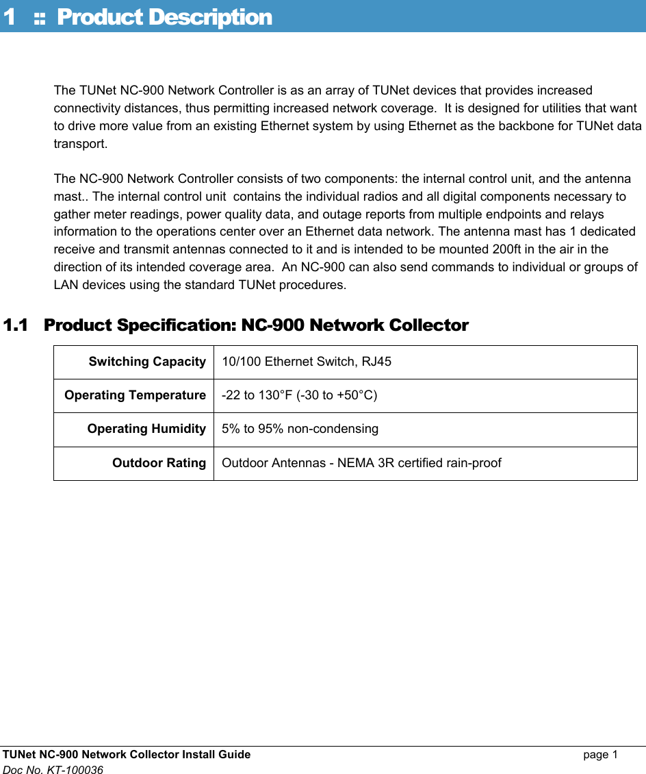

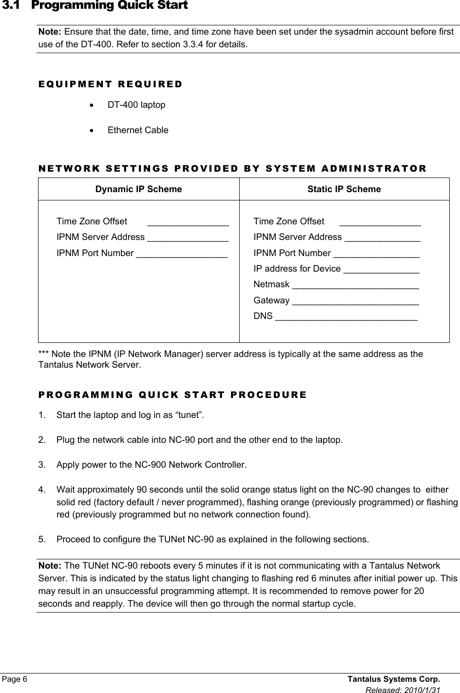
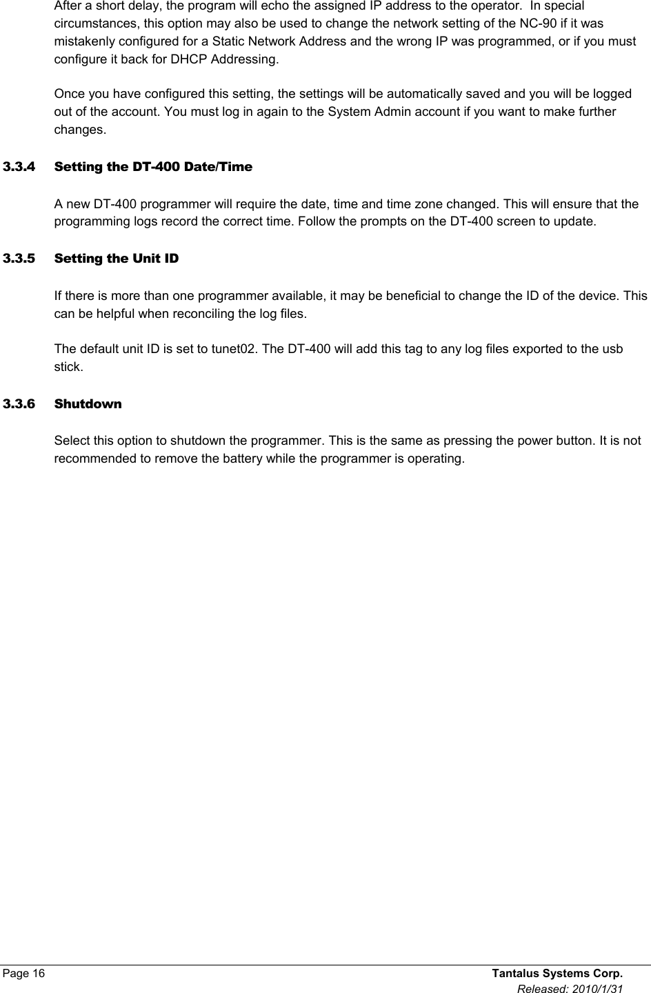
![TUNet NC-900 Network Collector Install Guide page 7 Doc No. KT-100036 3.2 TUNet User Account Before you can use the DT-400 programmer to program the NC-90, you must choose between a dynamic or static network addressing scheme. Tantalus recommends dynamic addressing in all cases, unless there is a specific technical reason that static addressing must be used instead. If you are unclear about which addressing scheme to choose, speak to your Network Administrator. LAUNCHING DEVICE CONFIGURATION 1. Log in to the DT-400 laptop. The DT-400 Device Configuration Tool will start automatically and you will see a menu of the available options. 2. Select one of the available options: Tantalus DT-400 Device Configuration Tool (version 200.0004). Select one of the following options 1) Configure for Static Network Address 2) Configure for DHCP 3) Options (DeviceIP=24.25.26.28) 4) Copy log file to USB memory stick 5) View log file 6) Help 7) Quit [2]>_](https://usermanual.wiki/Tantalus-Systems/N900/User-Guide-1363312-Page-11.png)
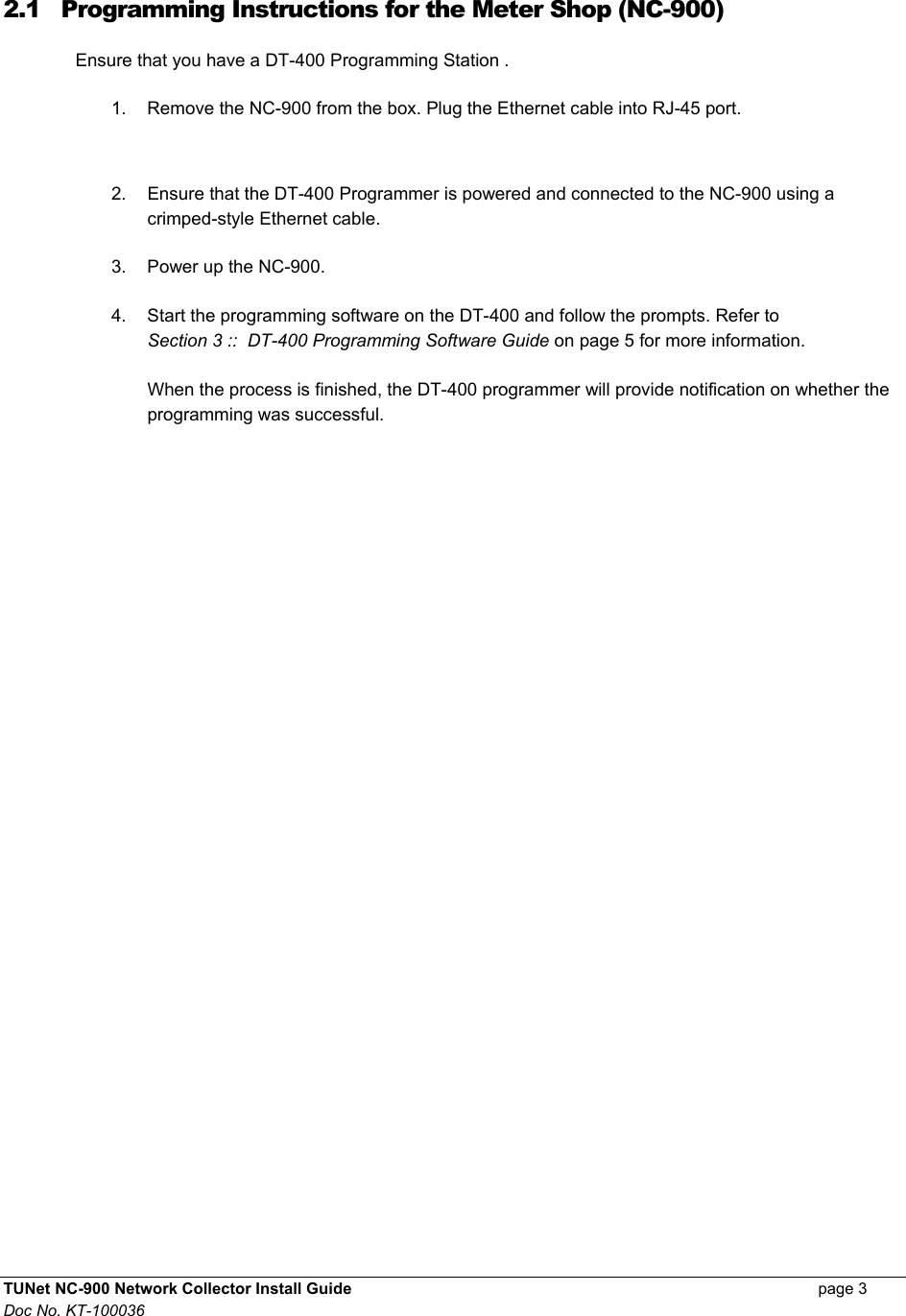
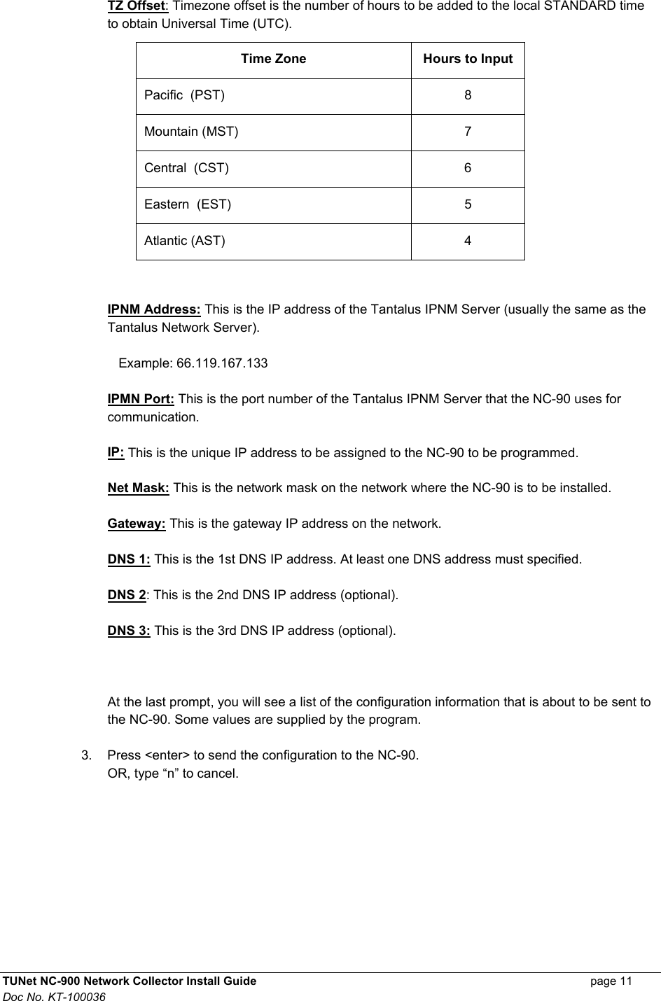
![Page 8 Tantalus Systems Corp. Released: 2010/1/31 3.2.1 Configuring a Dynamic Network Addressing Scheme Dynamic network addressing is the simplest network addressing scheme to setup and to maintain. TO CONFIGURE A DYNAMIC NETWORK ADDRESSING SCHEME Note: Make sure that the cable from the DT-400 is plugged into the NC-90 and is powered up. The NC-90 is ready for configuration when the status light on the NC-90 is either solid red, flashing orange, or flashing red. 1. To configure for DHCP, choose 2. 2. At each prompt, enter the network settings provided by your Network Administrator or press <enter> to accept the last entered values shown in brackets (green). Tantalus DT-400 Device Configuration Tool (version 200.0004). Select one of the following options 1) Configure for Static Network Address 2) Configure for DHCP 3) Options (DeviceIP=24.25.26.28) 4) Copy log file to USB memory stick 5) View log file 6) Help 7) Quit [2]>2 TZ offset(5)> IPNM Address (10.1.1.75)> IPNM Port(12345)> _ TZ Offset: Timezone offset is the number of hours to be added to the local STANDARD time to obtain Universal Time (UTC). Time Zone Hours to Input Pacific (PST) 8 Mountain (MST) 7 Central (CST) 6 Eastern (EST) 5 Atlantic (AST) 4](https://usermanual.wiki/Tantalus-Systems/N900/User-Guide-1363312-Page-12.png)
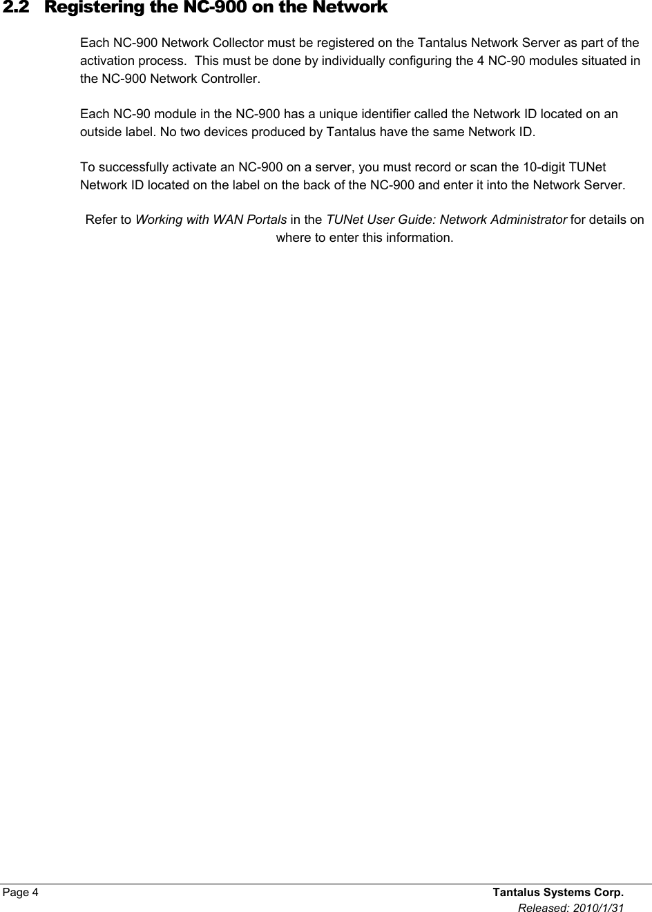
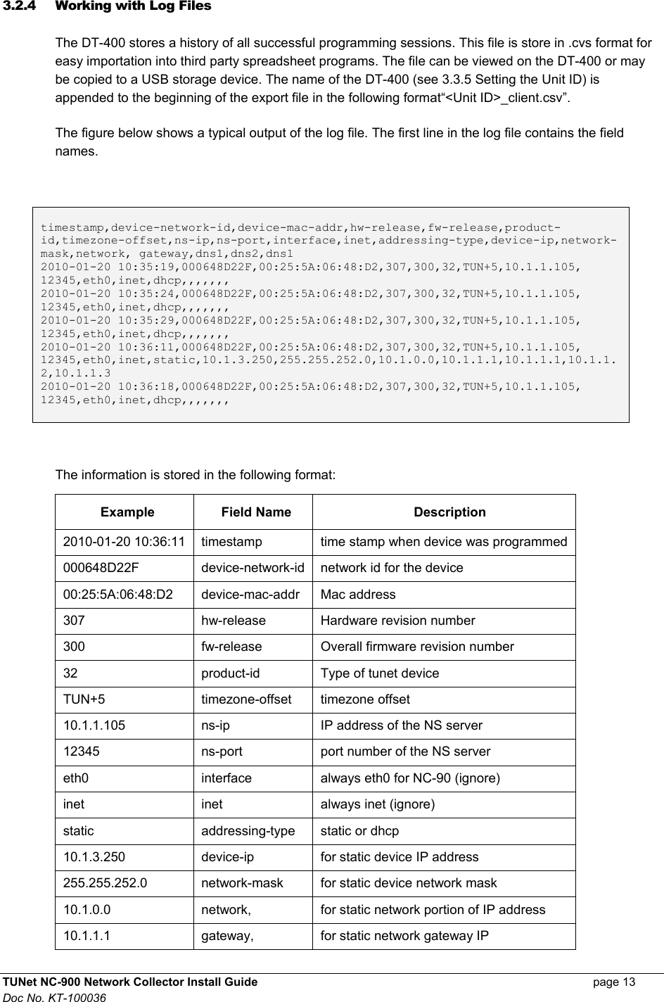
![TUNet NC-900 Network Collector Install Guide page 9 Doc No. KT-100036 IPNM Address: This is the IP address of the Tantalus IPNM Server (usually the same as the Tantalus Network Server). Example: 66.119.167.133 IPMN Port: This is the port number of the Tantalus IPNM Server that the NC-90 uses for communication. At the last prompt, you will see a list of the configuration information that is about to be sent to the NC-90. Some values are supplied by the program. 3. Press <enter> to send the configuration to the NC-90. OR, type “n” to cancel. [2]>2 TZ offset(5)> IPNM Address (10.1.1.75)> IPNM Port(12345)> The configuration file you are about to send: TZvar = TUN+5 IPNMAddr = 10.1.1.75 IPNMPort = 12345 Interface = eth0 InterfaceType = inet NetworkAddressing = dhcp Configure device? ( [ y ] n ):_](https://usermanual.wiki/Tantalus-Systems/N900/User-Guide-1363312-Page-13.png)
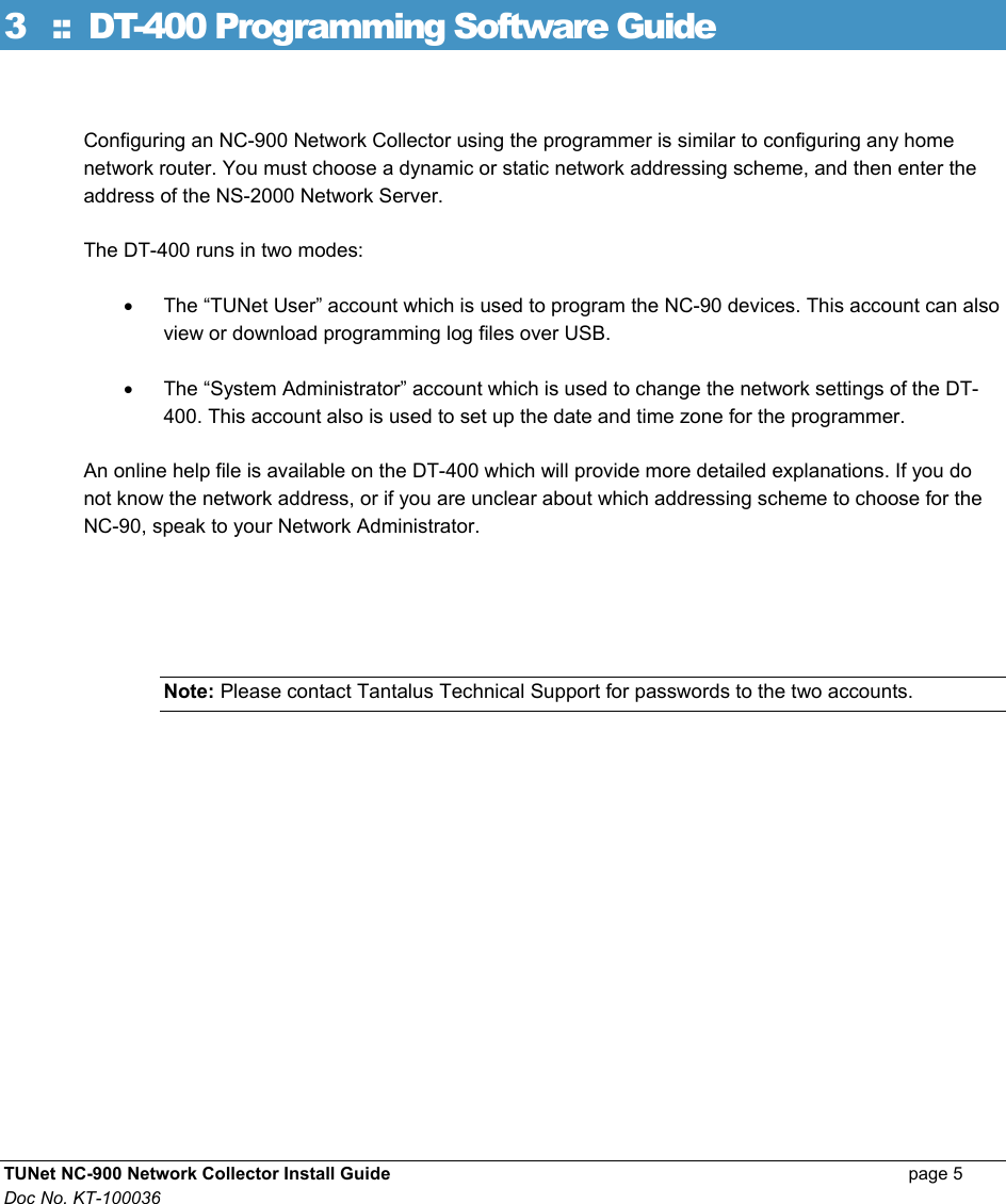
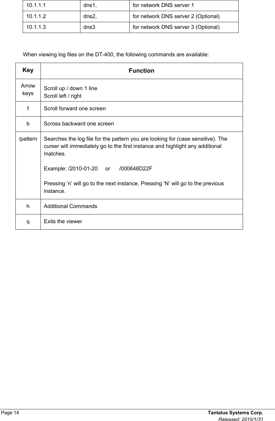
![Page 10 Tantalus Systems Corp. Released: 2010/1/31 3.2.2 Configuring a Static Network Addressing Scheme Static configuration requires additional variables and is much more difficult to change. In addition, an error in setting up a static addressing scheme may cause serious technical complications within your network. Warning An incorrect net mask setting may render the NC-90 unable to communicate with the Network Server or the DT-400. Warning Each NC-90 must have a unique network address. If multiple NC-90’s have the same network address, this will cause communications problems on the NS-2000 Network Server. TO CONFIGURE A STATIC NETWORK ADDRESSING SCHEME Note: Make sure that the cable from the DT-400 is plugged into the NC-90 and is powered up. The NC-90 is ready for configuration when the status light on the NC-90 is either solid red, flashing orange, or flashing red. 1. To configure for a static network address, choose 1. 2. At each prompt, enter the network settings provided by your Network Administrator or press <enter> to accept the last entered values shown in brackets (green). [2]>1 TZ offset(5)> IPNM Address >10.1.1.75 IPNM Port>12345 Device IP Address >10.1.50.32 Net Mask >255.255.0.0 Gateway >10.1.1.20 DNS 1 >10.1.1.25 DNS 2 > The configuration file you are about to send: TZvar = TUN+5 IPNMAddr = 10.1.1.75 IPNMPort = 12345 Interface = eth0 InterfaceType = inet NetworkAddressing = static IpcIP = 10.1.50.32 IpcMask = 255.255.0.0 IpcNetwork = 10.1.0.0 IpcGateway = 10.1.1.20 IpcDNS1 = 10.1.1.25 Configure device? ( [ y ] n ):_](https://usermanual.wiki/Tantalus-Systems/N900/User-Guide-1363312-Page-14.png)
![Page 12 Tantalus Systems Corp. Released: 2010/1/31 3.2.3 Configuring Options The DT-400 Programmer laptop is designed to be directly connected to the NC-90 without requiring a switch or router. The laptop has a DHCP server that distributes a specific IP address to any NC-90 that requests one. You can use the Device IP option to control which IP address the laptop assigns to the NC-90 for purposes of programming. Most of the time you will just use the default address. But under certain circumstances, you may want to update the IP address from the default setting. For example, you might do this if a statically addressed NC-90 requires reprogramming. CONFIGURING A SPECIFIC IP ADDRESS 1. To configure a specific IP address, choose 3. 2. Enter the IP address that the program will attempt to communicate to or press enter to accept the default in brackets. 3. Press <enter> to save the settings to the programmer. Tantalus DT-400 Device Configuration Tool (version 200.0004). Select one of the following options 1) Configure for Static Network Address 2) Configure for DHCP 3) Options (DeviceIP=24.25.26.28) 4) Copy log file to USB memory stick 5) View log file 6) Help 7) Quit [2]>3 Device IP Address (24.25.26.28)>_](https://usermanual.wiki/Tantalus-Systems/N900/User-Guide-1363312-Page-16.png)
![TUNet NC-900 Network Collector Install Guide page 15 Doc No. KT-100036 3.3 System Administration Account The System Administration account allows initial configuration of the DT-400 and provides pre-set network configurations that allow Tantalus Technical Support to provide remote servicing. Tantalus DT-400 System Administration (version 200.0004). Select one of the following options: 1) Configure DT-400 for TUNet programming 2) Configure for remote login using DHCP Addressing 3) Configure for remote login using Static Addressing 4) Set DT-400 date/time 5) Unit ID 6) Help 7) Shutdown 8) Quit [1]>_ 3.3.1 Configuring the DT-400 for TUNet programming This is the default state of the DT-400 when first powered up. In this configuration, the DT-400 runs an internal DHCP server to enable direct communications with a NC-90. Note: the DT-400 will not be able to communicate to an NC-90 that has a static address assigned to it. Refer to section 3.4 on how to configure the DT-400 for this scenario. Once you have configured this setting, the settings will be automatically saved and you will be logged out of the account. You must log in again to the System Admin account if you want to make further changes. 3.3.2 Configuring the DT-400 for remote login using DHCP Addressing Select this option if Tantalus personnel must remotely access the DT-400 when computers on your network are required to use DHCP. Make sure the DT-400 is connected to your corporate network so that it can get an IP address. After a successful IP lease is obtained, the program will display the assigned IP address. Please report this address to Tantalus. Once you have configured this setting, the settings will be automatically saved and you will be logged out of the account. You must log in again to the System Admin account if you want to make further changes. 3.3.3 Configuring the DT-400 for remote login using Static Addressing Select this option if Tantalus personnel must remotely access the DT-400 when computers on your network are required to use static IP assignment. You will be asked a series of questions (sample answer shown after '>' character): a) IP address for this unit: >10.1.3.80 b) Net Mask: >255.255.252.0 c) Gateway: >10.1.1.1 d) DNS: > 10.1.1.1](https://usermanual.wiki/Tantalus-Systems/N900/User-Guide-1363312-Page-19.png)