Taylor Blender Custard Machine Users Manual OpCvr
custard machine to the manual b8c74ba3-db74-4c5b-a51f-b49d8f52ce30
2015-02-02
: Taylor Taylor-Taylor-Blender-Custard-Machine-Users-Manual-449370 taylor-taylor-blender-custard-machine-users-manual-449370 taylor pdf
Open the PDF directly: View PDF ![]() .
.
Page Count: 58

Model C043
General Market
Custard Machine
Original Operating Instructions
068359--M
7/22/10 (Original Publication)
(Updated 8/2/12)

Complete this page for quick reference when service is required:
Taylor Distributor:
Address:
Phone:
Service:
Parts:
Date of Installation:
Information found on the C043 data label:
Model Number:
Serial Number:
Electrical Specs: Voltage Cycle
Phase
Maximum Fuse Size: Amps
Minimum Wire Ampacity: Amps
Part Number:
Information found on RC35 data label:
Model Number:
Serial Numbers:
Electrical Specs: Voltage Cycle
Phase
Maximum Fuse Size: Amps
Minimum Wire Ampacity: Amps
EJuly, 2010 Taylor
All rights reserved.
068359-M
The word Taylor and the Crown design
are registered trademarks in the United States
of America and certain other countries.
Taylor Company
750 N. Blackhawk Blvd.
Rockton, IL 61072

Model C043 Table of Contents
Table of Contents
Section 1 To the Installer 1............................................
Section 2 To the Operator 4...........................................
Section 3 Safety 5....................................................
Section 4 Operator Parts Identification 8...............................
C043 8................................................................
Beater Door & Hopper Assemblies 10......................................
Accessories 12..........................................................
Section 5 Important to Operator 13.....................................
Section 6 Operating Procedures 14.....................................
Assembly 14............................................................
Sanitizing 18............................................................
Priming - Custard 21.....................................................
Priming - Lemon Ice 23...................................................
Hold Cycle During Operation 26...........................................
Resuming Production During Operation 28..................................
Preparing for Shutdown 29................................................
Rinsing 31..............................................................
Cleaning 33.............................................................
Disassembly 35..........................................................
Brush Cleaning 36.......................................................
Section 7 Important: Operator Checklist 39..............................
During Cleaning and Sanitizing 39.........................................
Troubleshooting Bacterial Count 39........................................
Regular Maintenance Checks 39...........................................
Winter Storage 40........................................................

Table of Contents Model C043
Table of Contents - Page 2
Section 8 Troubleshooting Guide 41....................................
Section 9 Parts Replacement Schedule 42...............................
Section 10 Warranty Explanation 43......................................
Section 11 Parts Lists 44................................................
Wiring Diagrams 53......................................................
Note: Continuing research results in steady improvements; therefore, information
in this manual is subject to change without notice.
Note: Only instructions originating from the factory or its authorized translation
representative(s) are considered to be the original set of instructions.
EJuly, 2010 Taylor (Original Publication)
(Updated August, 2012)
All rights reserved.
068359-M
The word Taylor and the Crown design
are registered trademarks in the United States
of America and certain other countries.
Taylor Company
750 N. Blackhawk Blvd.
Rockton, IL 61072

1
Model C043 To the Installer
Section 1 To the Installer
The following are general installation instructions. For
complete installation details, please see the check out
card.
Installer Safety
In all areas of the world, equipment should be
installed in accordance with existing local codes.
Please contact your local authorities if you have any
questions.
Care should be taken to ensure that all basic safety
practices are followed during the installation and
servicing activities related to the installation and
service of Taylor equipment.
SOnly authorized Taylor service personnel
should perform installation and repairs on
the equipment.
SAuthorized service personnel should consult
OSHA Standard 29CFRI910.147 or the
applicable code of the local area for the
industry standards on lockout/tagout
procedures before beginning any installation
or repairs.
SAuthorized service personnel must ensure
that the proper PPE is available and worn
when required during installation and
service.
SAuthorized service personnel must remove
all metal jewelry, rings, and watches before
working on electrical equipment.
The main power supply(s) to the freezer must
be disconnected prior to performing any repairs.
Failure to follow this instruction may result in personal
injury or death from electrical shock or hazardous
moving parts as well as poor performance or damage
to the equipment.
Note:Allrepairsmustbeperformedbyan
authorized Taylor Service Technician.
This unit has many sharp edges that can
cause severe injuries.
Site Preparation
Review the area where the unit will be installed before
uncrating the unit. Make sure all possible hazards to
the user or equipment have been addressed.
Air Cooled Units
DO NOT obstruct air intake and discharge openings:
C043: The minimum air clearance requirement is 3”
(76 mm) on one side and the rear of the unit, and 0”
on the other side. (Note: A minimum clearance of
36” [914 mm] is required on one side to allow for the
installation and removal of the side drip pan.)
RC35: Requires a minimum air clearance of 6”
(152 mm) on three sides. An air deflector must be
installed on the condenser side if the floor clearance
is less than 5” (127 mm). (Note: The legs are
typically mounted on 4” x 4” lumber to achieve the
minimum floor clearance.)
Failure to allow adequate air clearance can reduce
the refrigeration capacity of the freezer and possibly
cause permanent damage to the compressor.
For Indoor Use Only: This unit is designed to operate
indoors, under normal ambient temperatures of
70_-75_F(21_-24_C). The freezer has successfully
performed in high ambient temperatures of
104_(40_C) at reduced capacities.
This unit must NOT be installed in an area
where a water jet or hose can be used. NEVER use a
water jet or hose to rinse or clean the unit. Failure to
follow this instruction may result in electrocution.
2Model C043To the Installer
111216
This unit must be installed on a level surface
to avoid the hazard of tipping. Extreme care should be
taken in moving this equipment for any reason. Two or
more persons are required to safely move this unit.
Failure to comply may result in personal injury or
equipment damage.
Uncrate the unit and inspect it for damage. Report any
damage to your Taylor Distributor.
This piece of equipment is made in the USA and has
USA sizes of hardware. All metric conversions are
approximate and vary in size.
Electrical Connections
In the United States, this equipment is intended to be
installed in accordance with the National Electrical
Code (NEC), ANSI/NFPA 70-1987. The purpose of
the NEC code is the practical safeguarding of persons
and property from hazards arising from the use of
electricity. This code contains provisions considered
necessary for safety. In all other areas of the world,
equipment should be installed in accordance with the
existing local codes. Please contact your local
authorities.
FOLLOW YOUR LOCAL ELECTRICAL CODES!
Each unit requires one power supply for each data
label on the unit. Check the data label on the freezer
for branch circuit overcurrent protection or fuse, circuit
ampacity and other electrical specifications. Refer to
the wiring diagram provided inside the electrical box for
proper power connections.
CAUTION: THIS EQUIPMENT MUST BE
PROPERLY GROUNDED! FAILURE TO DO SO
CAN RESULT IN SEVERE PERSONAL INJURY
FROM ELECTRICAL SHOCK!
DO NOT operate this freezer with larger fuses
than specified on the unit's data label. Failure to follow
this instruction may result in electrocution or damage
to the machine.
This unit is provided with an equipotential
grounding lug that is to be properly attached to the rear
of the frame by the authorized installer. The installation
location is marked by the equipotential bonding
symbol (5021 of IEC 60417-1) on both the removable
panel and the equipment's frame.
Stationary appliances which are not equipped
with a power cord and a plug or another device to
disconnect the appliance from the power source must
have an all-pole disconnecting device with a contact
gap of at least 3 mm installed in the external
installation.
Appliances that are permanently connected to
fixed wiring and for which leakage currents may
exceed 10 mA, particularly when disconnected, not
used for long periods, or during initial installation, shall
have protective devices such as a GFI to protect
against the leakage of current, installed by the
authorized personnel to the local codes.
Supply cords used with this unit shall be
oil-resistant, sheathed flexible cable not lighter than
ordinary polychloroprene or other equivalent synthetic
elastomer-sheathed cord (Code designation 60245
IEC 57) installed with the proper cord anchorage to
relieve conductors from strain, including twisting, at
the terminals and protect the insulation of the
conductors from abrasion.
Beater rotation must be counter-clockwise
as viewed looking into the freezing cylinder.
Note: The following procedures should be
performed by a trained service technician.
To correct rotation on a three-phase unit,
interchange any two incoming power supply lines at
the freezer main terminal block only.
To correct rotation on a single-phase unit, change
the leads inside the beater motor. (Follow diagram
printed on motor.)
Electrical connections are made directly to the
terminal block provided behind the lower rear panel.

3
Model C043 To the Installer
Refrigerant
In consideration of our environment, Taylor
proudly uses only earth friendly HFC refrigerants. The
HFC refrigerant used in this unit is R404A. This
refrigerant is generally considered non-toxic and
non-flammable, with an Ozone Depleting Potential
(ODP) of zero (0).
However, any gas under pressure is potentially
hazardous and must be handled with caution.
NEVER fill any refrigerant cylinder completely with
liquid. Filling the cylinder to approximately 80% will
allow for normal expansion.
Refrigerant liquid sprayed onto the skin may
cause serious damage to tissue. Keep eyes and skin
protected. If refrigerant burns should occur, flush
immediately with cold water. If burns are severe, apply
ice packs and contact a physician immediately.
Taylor reminds technicians to be cautious of
government laws regarding refrigerant recovery,
recycling, and reclaiming systems. If you have any
questions regarding these laws, please contact the
factory Service Department.
WARNING: R404A refrigerant used in
conjunction with polyolester oils is extremely moisture
absorbent. When opening a refrigeration system, the
maximum time the system is open must not exceed 15
minutes. Cap all open tubing to prevent humid air or
water from being absorbed by the oil.

4Model C043To the Operator
Section 2 To the Operator
Your freezer has been carefully engineered and
manufactured to give you dependable operation.
This unit, when properly operated and cared for, will
produce a consistent quality product. Like all
mechanical products, it will require cleaning and
maintenance. A minimum amount of care and
attention is necessary if the operating procedures
outlined in this manual are followed closely.
This Operator's Manual should be read before
operating or performing any maintenance on your
equipment.
Your Taylor freezer will NOT eventually compensate
for and correct any errors during the set-up or filling
operations. Thus, the initial assembly and priming
procedures are of extreme importance. It is strongly
recommended that personnel responsible for the
equipment's operation, both assembly and
disassembly, go through these procedures together
in order to be properly trained and to make sure that
no confusion exists.
In the event you should require technical assistance,
please contact your local authorized Taylor
Distributor.
Note: Warranty is valid only if the parts are
authorized Taylor parts, purchased from an
authorized Taylor Distributor, and the required
service work is provided by an authorized Taylor
service technician. Taylor reserves the right to deny
warranty claims on equipment or parts if
non-approved parts or refrigerant were installed in
the machine, system modifications were performed
beyond factory recommendations, or it is determined
that the failure was caused by neglect or abuse.
If the crossed out wheeled bin symbol is
affixed to this product, it signifies that this product is
compliant with the EU Directive as well as other
similar legislation in effect after August 13, 2005.
Therefore, it must be collected separately after its
use is completed, and cannot be disposed as
unsorted municipal waste.
The user is responsible for returning the product to
the appropriate collection facility, as specified by
your local code.
For additional information regarding applicable local
laws, please contact the municipal facility and/or
local distributor.
Compressor Warranty Disclaimer
The refrigeration compressors on this machine are
warranted for the term indicated on the warranty
card accompanying this machine. However, due to
the Montreal Protocol and the U.S. Clean Air Act
Amendments of 1990, many new refrigerants are
being tested and developed, thus seeking their way
into the service industry. Some of these new
refrigerants are being advertised as drop-in
replacements for numerous applications. It should
be noted that in the event of ordinary service to this
machine's refrigeration system, only the refrigerant
specified on the affixed data label should be
used. The unauthorized use of alternate refrigerants
will void your compressor warranty. It will be the
owner's responsibility to make this fact known to any
technician he employs.
It should also be noted that Taylor does not warrant
the refrigerant used in its equipment. For example, if
the refrigerant is lost during the course of ordinary
service to this machine, Taylor has no obligation to
either supply or provide its replacement either at
billable or unbillable terms. Taylor does have the
obligation to recommend a suitable replacement if
the original refrigerant is banned, obsoleted, or no
longer available during the five year warranty of the
compressor.
The Taylor Company will continue to monitor the
industry and test new alternates as they are being
developed. Should a new alternate prove, through
our testing, that it would be accepted as a drop-in
replacement, then the above disclaimer would
become null and void. To find out the current status
of an alternate refrigerant as it relates to your
compressor warranty, call the local Taylor Distributor
or the Taylor Factory. Be prepared to provide the
Model/Serial Number of the unit in question.

5
Model C043 Safety
111216
Section 3 Safety
We at Taylor Company are concerned about the safety
of the operator when he or she comes in contact with
the freezer and its parts. Taylor has gone to extreme
efforts to design and manufacture built-in safety
features to protect both you and the service technician.
As an example, warning labels have been attached to
the freezer to further point out safety precautions to the
operator.
IMPORTANT - Failure to adhere to the
following safety precautions may result in severe
personal injury or death. Failure to comply with
these warnings may damage the machine and its
components. Component damage will result in
part replacement expense and service repair
expense.
DO NOT operate the freezer without reading
this Operator Manual. Failure to follow this instruction
may result in equipment damage, poor freezer
performance, health hazards, or personal injury.
Per IEC 60335-1 and its part 2 standards, “This
appliance is to be used only by trained personnel. It is
not intended for use by children or people with reduced
physical, sensory, or mental capabilities, or lack of
experience and knowledge, unless given supervision
or instruction concerning the use of the appliance by
a person responsible for their safety.”
This unit is provided with an equipotential
grounding lug that is to be properly attached to the rear
of the frame by the authorized installer. The installation
location is marked by the equipotential bonding
symbol (5021 of IEC 60417-1) on both the removable
panel and the equipments frame.
DO NOT use a water jet to clean or rinse the
freezer. Failure to follow these instructions may result
in serious electrical shock.
SDO NOT operate the freezer unless it is
properly grounded.
SDO NOT operate the freezer with larger
fuses than specified on the freezer data
label.
SAll repairs must be performed by an
authorized Taylor service technician. The
main power supplies to the machine must
be disconnected prior to performing any
repairs.
SCord Connected Units: Only Taylor
authorized service technicians may install a
plug on this unit.
SStationary appliances which are not
equipped with a power cord and a plug or
another device to disconnect the appliance
from the power source, must have an
all-pole disconnecting device with a contact
gap of at least 3 mm installed in the
external installation.
SAppliances that are permanently connected
to fixed wiring and for which leakage
currents may exceed 10 mA, particularly
when disconnected or not used for long
periods, or during initial installation, shall
have protective devices, such as a GFI, to
protect against the leakage of current and
be installed by authorized personnel to the
local codes.
SSupply cords used with this unit shall be
oil-resistant, sheathed, flexible cable not
lighter than ordinary polychloroprene or
other equivalent synthetic
elastomer-sheathed cord (Code designation
60245 IEC 57) installed with the proper cord
anchorage to relieve conductors from strain,
including twisting, at the terminals and
protect the insulation of the conductors from
abrasion.
Failure to follow these instructions may result in
electrocution. Contact your local authorized Taylor
Distributor for service.

6Model C043Safety
SDO NOT allow untrained personnel to
operate this machine.
SDO NOT operate the freezer unless all
service panels and access doors are
restrained with screws.
SDO NOT remove any internal operating
parts (example: freezer door, beater,
scraper blades, etc.) unless all control
switches are in the OFF position.
Failure to follow these instructions may result in severe
personal injury from hazardous moving parts.
This unit has many sharp edges that can
cause severe injuries.
SDO NOT put objects or fingers in the fill or
discharge openings. This may contaminate
the product and cause severe personal
injury.
SUSE EXTREME CAUTION when removing
the beater asssembly. The scraper blades
are very sharp.
This freezer must be placed on a level
surface. Failure to comply may result in personal injury
or equipment damage.
Cleaning and sanitizing schedules are
governed by your state or local regulatory agencies
and must be followed accordingly. Please refer to the
cleaning section of this manual for the proper
procedure to clean this unit.
DO NOT obstruct air intake and discharge
openings:
C043: The minimum air clearance requirement is 3”
(76 mm) on one side and the rear of the unit, and 0”
on the other side. (Note: A minimum clearance of
36” [914 mm] is required on one side to allow for the
installation and removal of the side drip pan.)
RC35: Requires a minimum air clearance of 6”
(152 mm) on three sides. An air deflector must be
installed on the condenser side if floor clearance is
less than 5” (127 mm).
Failure to allow adequate clearance can reduce the
refrigeration capacity of the freezer and possibly
cause permanent damage to the compressor.
For Indoor Use Only: This unit is designed to operate
indoors, under normal ambient temperatures of 70_-
75_F(21_-24_C). The freezer has successfully
performed in high ambient temperatures of
104_(40_C) at reduced capacities.
NOISE LEVEL: Airborne noise emission does not
exceed 78 dB(A) when measured at a distance of 1.0
meter from the surface of the machine and at a height
of 1.6 meters from the floor.

7
Model C043 Safety
Notes:
8Model C043Operator Parts Identification
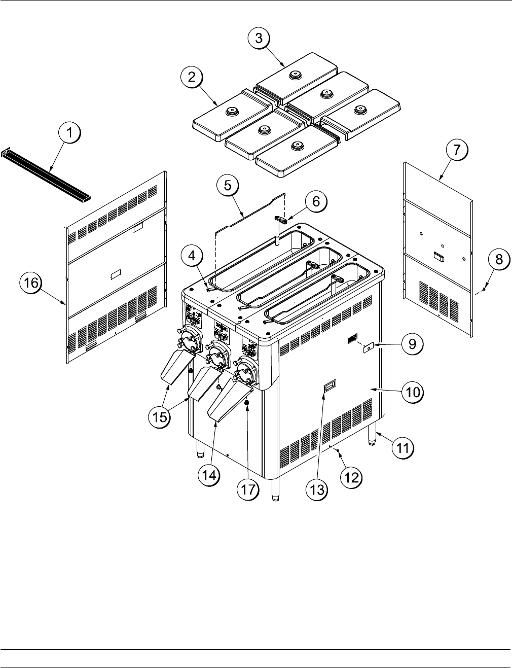
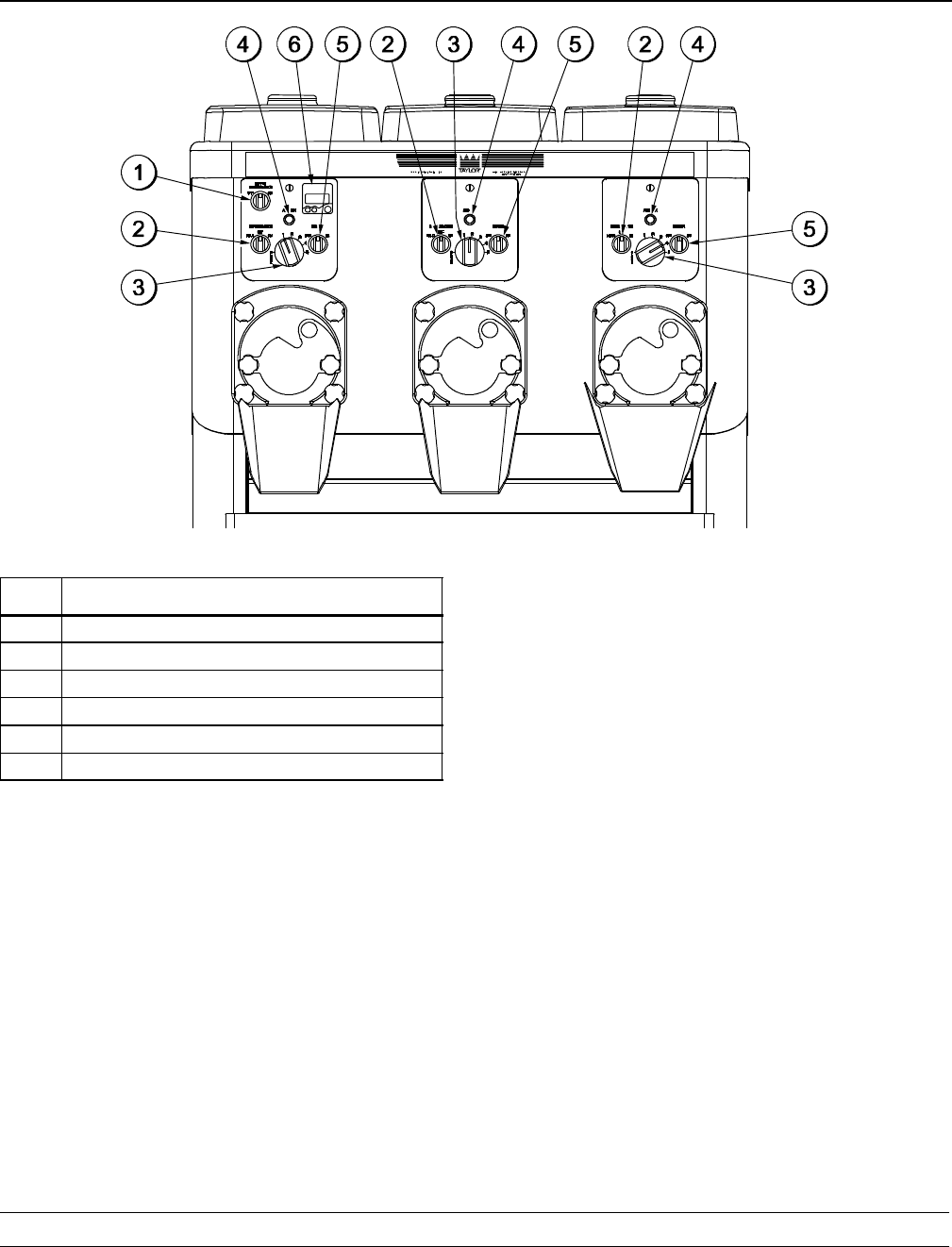
Section 4 Operator Parts Identification
C043
Figure 1

9
Model C043 Operator Parts Identification
Exploded View Parts Identification
ITEM DESCRIPTION PART NO.
1TRAY A.-DRIP X63636
2COVER-HOPPER-FRONT INS 065701
3COVER-HOPPER-REAR INS 065700
4LEVER A.-FLOW REG X64316
5ROD-FLOW CONTROL 063593
6TUBE A.-FEED PLASTIC X67453
7PANEL A.-REAR X63715
8SCREW-1/4-20X3/8 PHIL TRUSS 038872
9COVER A.-PANEL-SIDE *C043 X65637
ITEM DESCRIPTION PART NO.
10 PANEL A.-SIDE RIGHT X63720
11 LEG-8” 2”OD-3/4-10 STUD-HEX 044652
12 SCREW-1/4-20 X 3/8 PHIL TRUS 038872
13 HANDLE-STNLS FLUSH PULL 019043
14 CHUTE-LONG 063619
15 CHUTE-SHORT 063618
16 PANEL A.-SIDE LEFT X63724
17 NUT-STUD 034383
10 Model C043Operator Parts Identification
110207
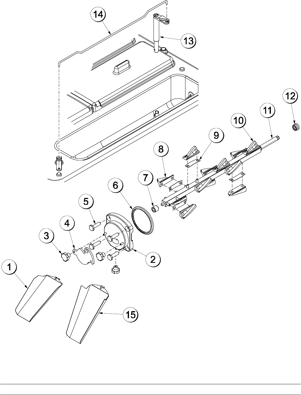
Beater Door & Hopper Assemblies
Figure 2

11
Model C043 Operator Parts Identification
110207
Beater Door & Hopper Assemblies Parts Identification
ITEM DESCRIPTION PART NO.
1CHUTE-SHORT 063618
2DOOR A. C043 X63611-SER
3NUT-STUD 043666
4PLATE-DRAW ARM 063614
5NUT-STUD 034383
6GASKET-DOOR HT 4” DOUBLE 048926
7BEARING-DOOR-FRONT 064315
8BLADE-SCRAPER 30 PITCH 063656
ITEM DESCRIPTION PART NO.
9SPRING-DASHER BLADE 063693
10 BLADE-SCRAPER-REAR 063640
11 SHAFT A.-DASHER X63689
12 SEAL-DRIVE SHAFT 032560
13 TUBE A.-FEED PLASTIC X67453
14 ROD-FLOW CONTROL 063593
15 CHUTE-LONG 063619
12 Model C043Operator Parts Identification
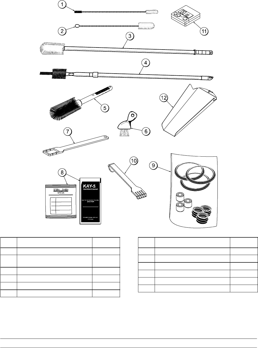
Accessories
Figure 3
ITEM DESCRIPTION PART NO.
1BRUSH-DBL END-PUMP & FEED 013072
2BRUSH-DRAW VALVE 1”OD X
2”X17” 013073
*3 BRUSH-BARREL 063843
*4 BRUSH-REAR BRG 063844
5BRUSH-MIX PUMP BODY 3”X7” 023316
6BRUSH-END-DOOR-SPOUT-SS 039719
ITEM DESCRIPTION PART NO.
7TOOL-DASHER SHAFT REMOVE 063623
**8 SANITIZER SEE NOTE
9KIT A.-TUNE UP X64743
10 RAKE-FINGERGUARD 064888
11 TIMER-COUNTDOWN-DIGITAL 065425
12 CHUTE-LONG 063619
*For replacement brush heads only, order 063843-1 and
063844-1.
** A sample container of sanitizer is sent with the unit.
For reorders, order Stera Sheen part no. 055492 (100
packs) or Kay-5 part no. 041082 (125 packs).
13
Model C043 Operator Parts Identification
Section 5 Important to Operator
Figure 4
ITEM DESCRIPTION
1HOPPER REFRIGERATION SWITCH
2OPERATIONAL REFRIGERATION SWITCH
3FLOW ADJUSTMENT KNOB
4MIX LOW INDICATOR LIGHT
5BEATER MOTOR SWITCH
6DIGITAL COUNTDOWN TIMER
Hopper Refrigeration Switch
The hopper refrigeration switch activates the hopper
refrigeration.
Operational Refrigeration Switch
Place the operational refrigeration switch in the “ON”
position to allow the product to dispense. During “No
Sale” periods, place the switch in the “HOLD”
position to keep the product refrigerated in the
freezing cylinder.
Flow Adjustment Knob
The flow adjustment knob adjusts the flow of product
into the freezing cylinders.
Note: Whenever an adjustment is made, first turn
the adjustment knob all the way to “5” and then back
to the desired number.
Mix Low Indicator Light
When the mix low indicator light is illuminated, the
mix hopper has a low supply of mix and should be
refilled as soon as possible.
Beater Motor Switch
The beater motor switch activates the beater motor.
Digital Countdown Timer
The digital countdown timer is used to keep track of
the time needed to control product quality.
14 Model C043Operating Procedures
Section 6 Operating Procedures
This machine is a three flavor custard freezer. It has
three 30 quart (28 liter) hoppers. The mix flows by
gravity through an adjustable flow control into the
freezing cylinders. This unit has been designed to
produce a rich tasting custard product that can be
drawn off and served from a holding cabinet. The
overrun is typically 20-25% and varies depending on
the mix formulation and the finished product
temperature (18 to 21°F [-7.8 to -6.1°C]).
We begin our instructions at the point where we find
the parts disassembled and laid out to air dry from
the previous brush cleaning.
The following procedures will show you how to
assemble the parts into the freezer, sanitize them,
and prime the freezer with fresh mix.
If you are disassembling the freezer for the first time
or need information to get to this starting point in our
instructions, turn to “Disassembly” on page 35 and
start there.
Assembly
MAKE SURE THE BEATER MOTOR
SWITCH IS IN THE “OFF” POSITION. Failure to
follow this instruction may cause severe personal
injury to fingers or hands from hazardous moving
parts.
Beater Shaft, Scraper Blade, and Feed
Tube Assembly
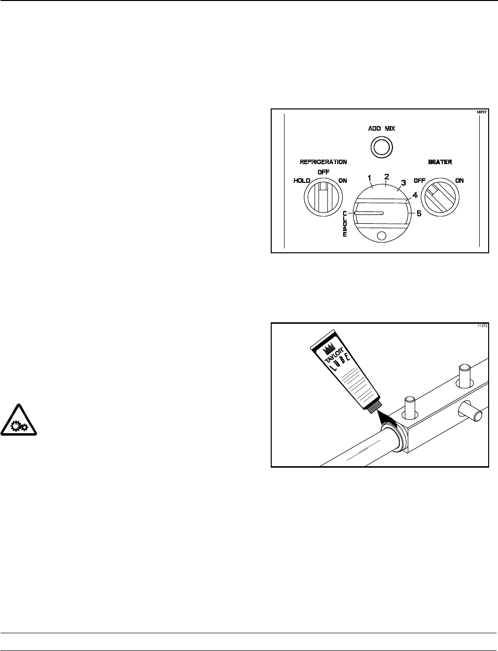
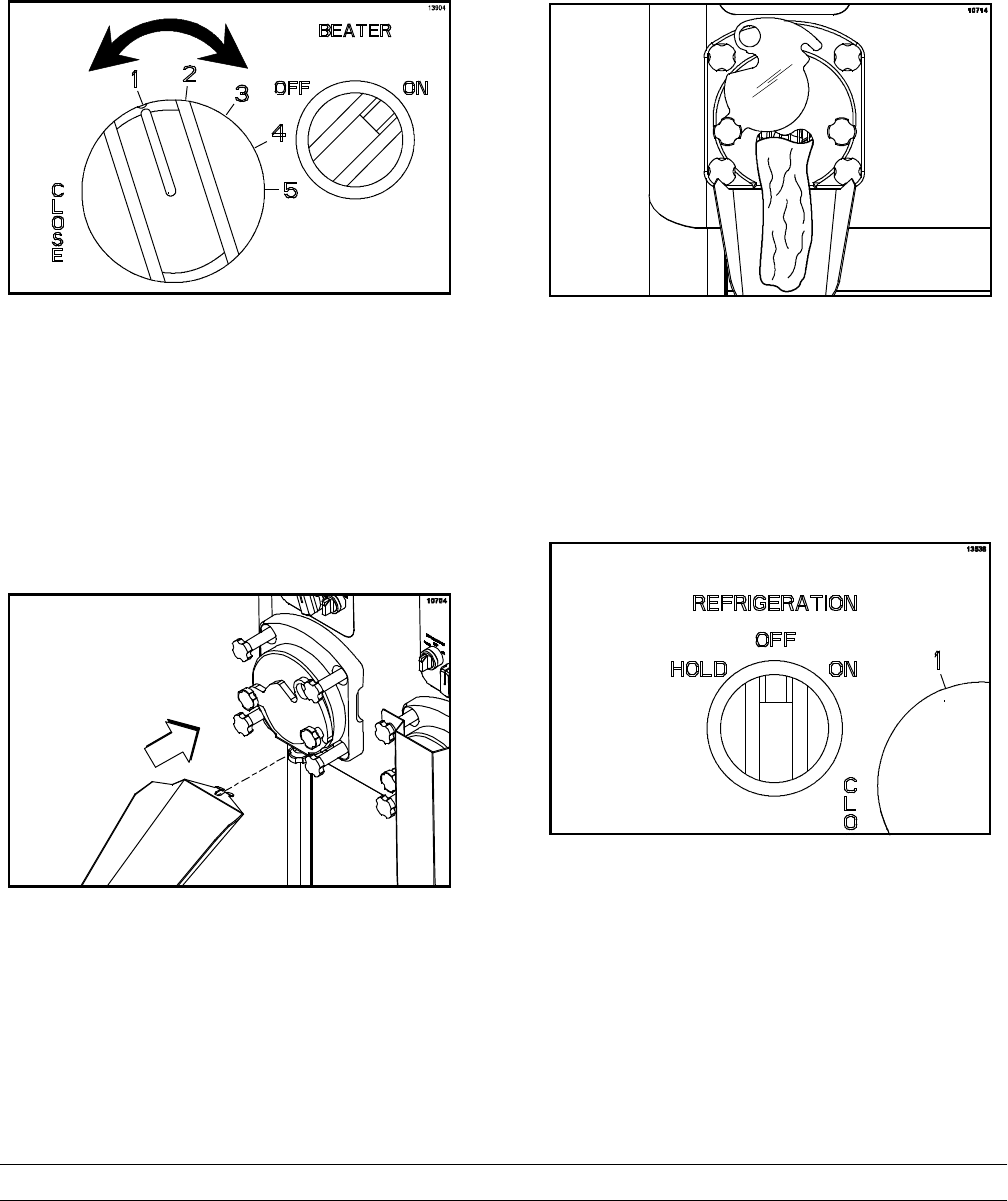
Step 1
Verify that the refrigeration switch and the beater
motor switch are both in the “OFF” position.
Figure 5
Step 2
Place a bead of lubricant around the groove of the
beater shaft.
Figure 6
15
Model C043 Operating Procedures
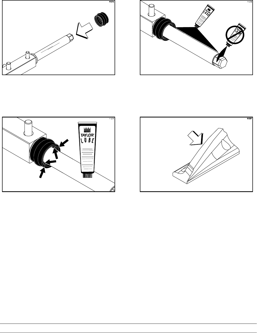
Step 3
Slide the seal over the shaft and groove until it
snaps into place.
Figure 7
Step 4
Fill the inside portion of the seal with 1/4” (6 mm)
more lubricant and lubricate the flat side of the seal
that fits onto the rear shell bearing.
Figure 8
Step 5
Lubricate the beater shaft. IMPORTANT! DO
NOT lubricate the hex end of the beater shaft.
Figure 9
Step 6
Inspect each scraper blade for any nicks or signs of
excessive wear. If any nicks or signs of wear are
present, replace the blade.
Figure 10
16 Model C043Operating Procedures
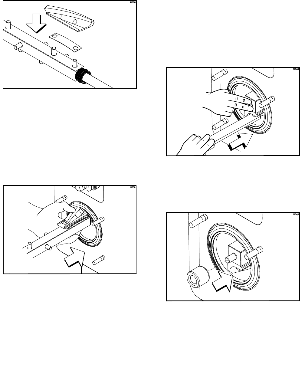
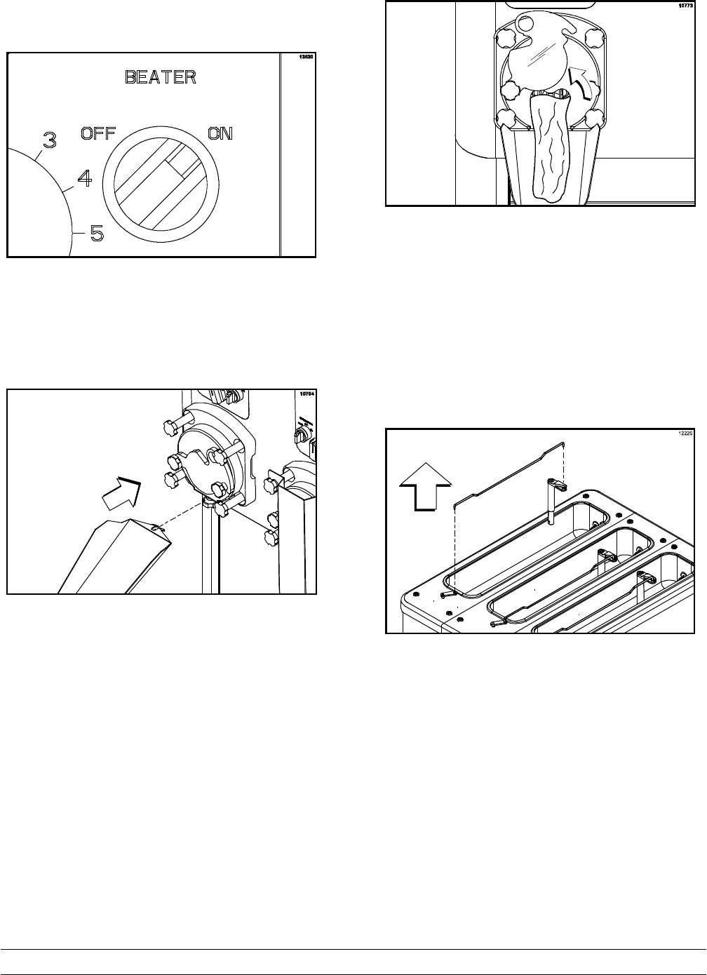
Step 7
Starting at the hex end of the beater shaft, place a
metal leaf spring (arched upward) over the two pins
closest to that end. Install the long scraper blade on
top of the leaf spring. (Note: There is only one long
scraper blade per beater.)
Figure 11
Step 8
Place a leaf spring and a short scraper blade on the
next set of pins.
Step 9
Hold the two leaf springs and scraper blades in
place. Slide the beater shaft into the freezing
cylinder until the scraper blades are held in place by
the freezing cylinder. Rotate the beater shaft
counter-clockwise until the next set of pins is facing
up.
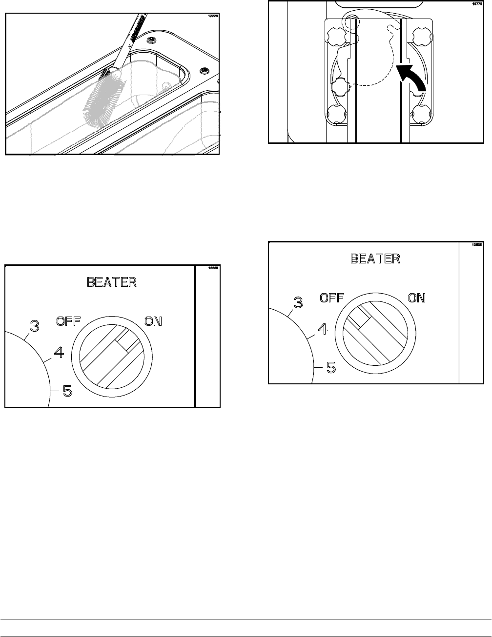
Figure 12
Step 10
Place a leaf spring and a short scraper blade on the
next set of pins. Slide the beater shaft into the
freezing cylinder until the blade is held in place by
the freezing cylinder. Rotate the beater shaft
counter-clockwise until the next set of pins is facing
up.
Step 11
Continue adding leaf springs and short scraper
blades to the beater shaft until all 12 blades are
installed.
Step 12
Slide the beater shaft into the freezing cylinder,
rotating the beater shaft slightly counter-clockwise.
Engage the hex end firmly into the drive coupling at
the back of the machine. The square portion of the
beater shaft assembly should fit completely inside
the freezing cylinder. The bearing support pin will
extend beyond the freezing cylinder.
Note: It may be helpful to use the beater removal
tool to turn the beater while installing the beater.
Figure 13
Note: The drip pan is a convenient place to store
the beater removal tool.
Step 13
Install the front bearing on the bearing support pin.
Figure 14
Step 14
Repeat the assembly instructions on the
remaining freezing cylinders.
17
Model C043 Operating Procedures
111216
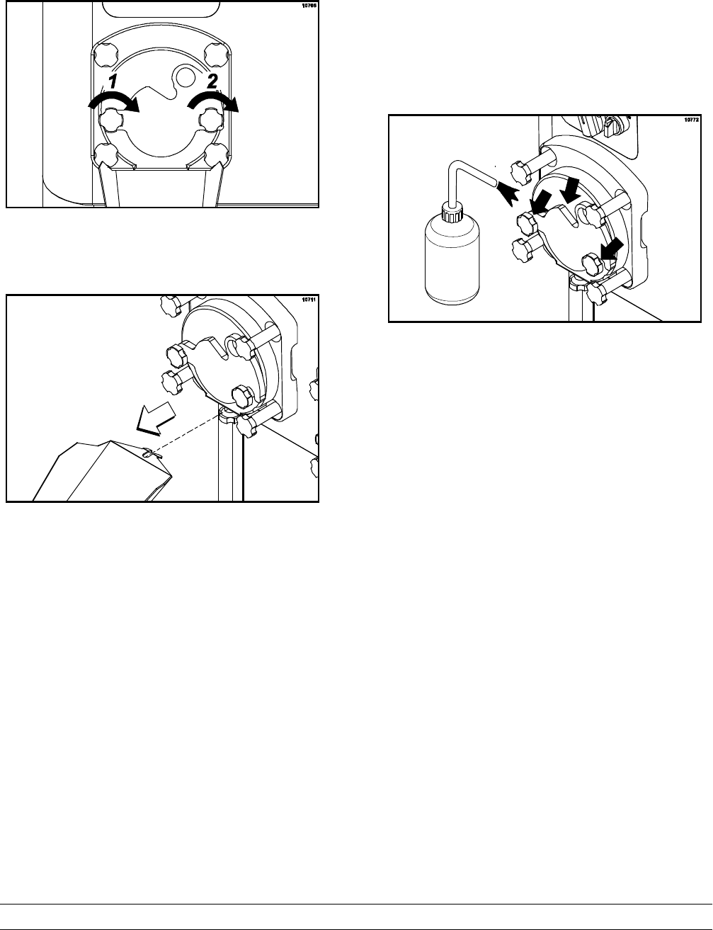
Door Assembly
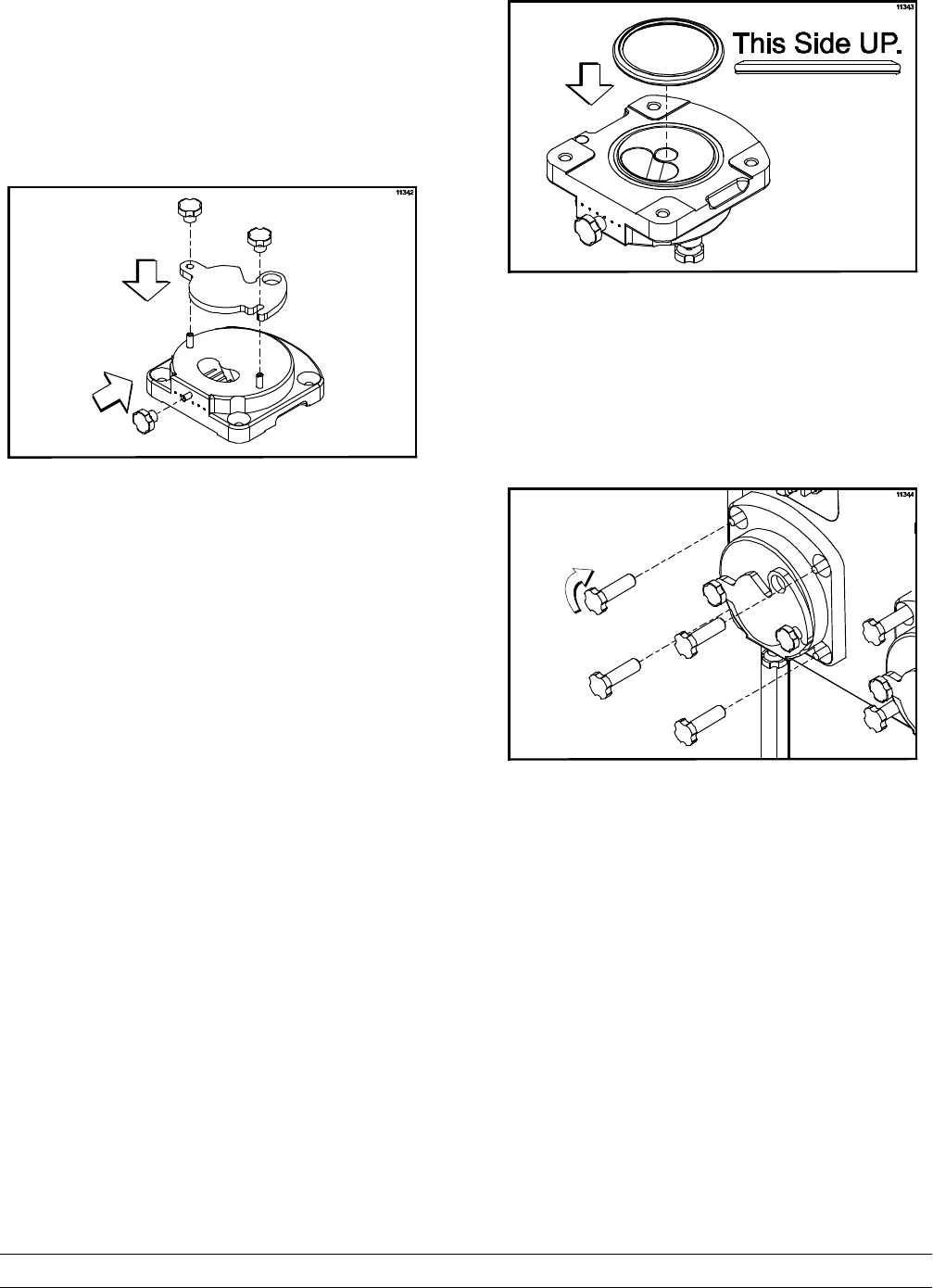
Step 1
With the door in a horizontal position, install the
draw arm plate. Install all three short stud nuts and
leave them loose.
Figure 15
Step 2
Turn the door over and install the door gasket.
Note: DO NOT lubricate the gasket, as this will
cause the gasket to leak over time.
Step 3
Press all around the gasket to ensure a flush,
secure fit in the groove. The gasket may have to be
stretched slightly to get it into the proper position.
To ensure that the gasket is correctly positioned,
verify that the middle section of the gasket is arched
upward. If the middle section of the gasket is
concave, or extends into the middle of the seal, turn
the gasket over, as it is upside down.
Figure 16
Step 4
Seat the door on the freezer studs. To ensure the
door gasket doesn't fall off, hold the door flush with
the freezing cylinder with one hand while installing
the stud nuts with the other hand. Hand-tighten the
stud nuts equally in a criss-cross pattern to insure
the door is snug.
Figure 17
Step 5
Repeat the assembly instructions on the
remaining freezing cylinders.
18 Model C043Operating Procedures
Sanitizing
Step 1
Using lukewarm water, prepare an approved 100
PPM sanitizing solution (examples: 5 gal. [19 liters]
of Kay-5Ror 4 gal. [15 liters] of Stera-SheenR).
USE WARM WATER AND FOLLOW THE
MANUFACTURER'S SPECIFICATIONS.
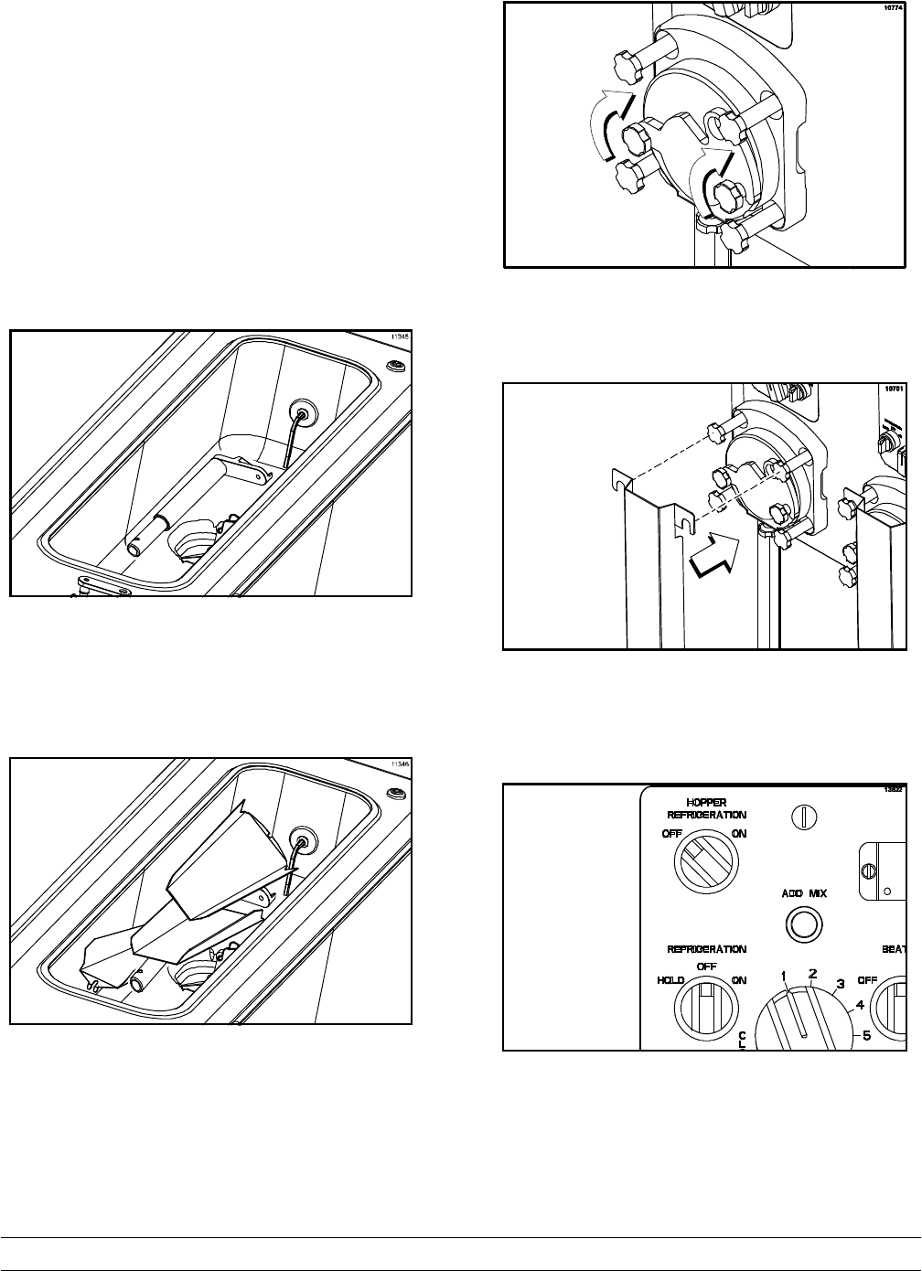
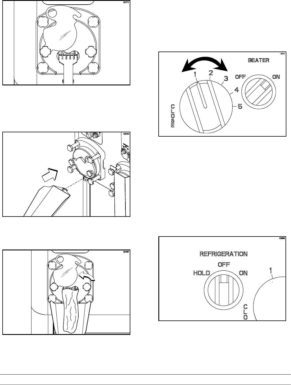
Step 2
Place the feed tube and the flow control rod flat on
the bottom of the hopper.
Figure 18
Step 3
Place the product chutes in the hopper.
Figure 19
Step 4
Make sure the draw arm plate is closed and the
short door stud nuts are snug.
Figure 20
Step 5
Attach the splash guards to the door studs.
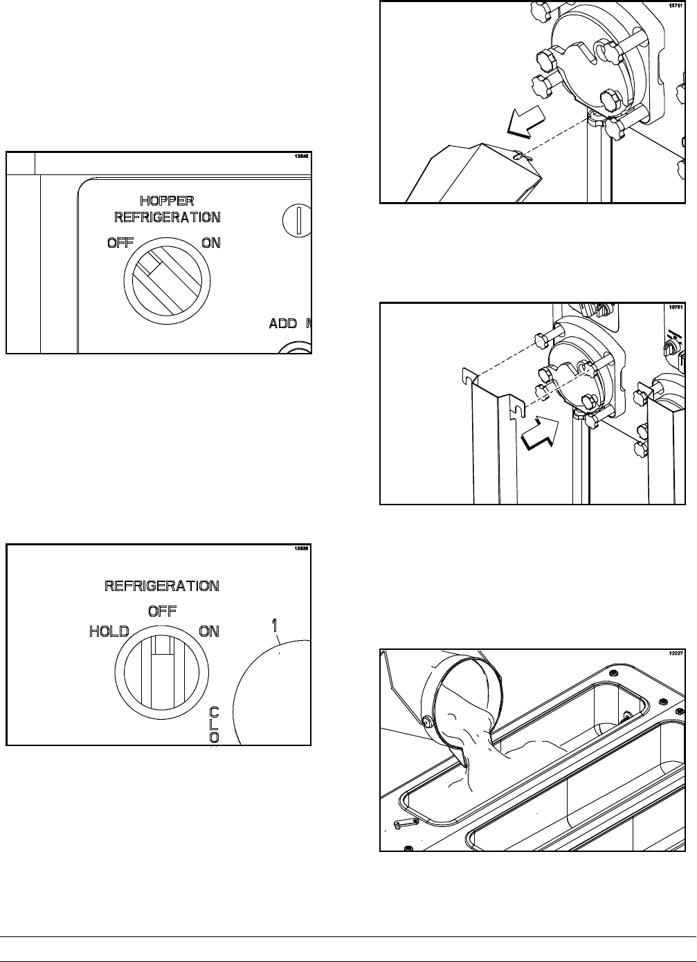
Figure 21
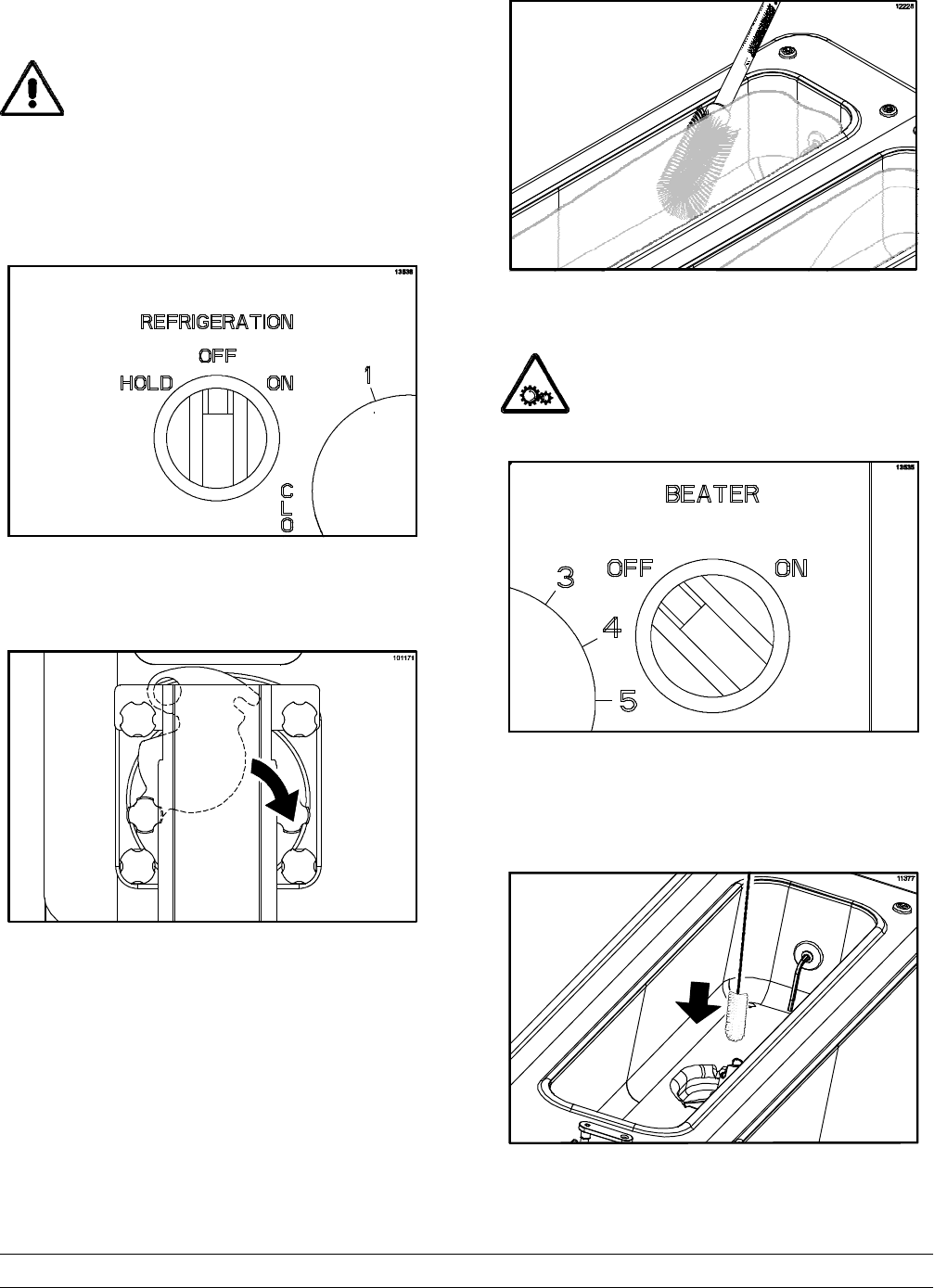
Step 6
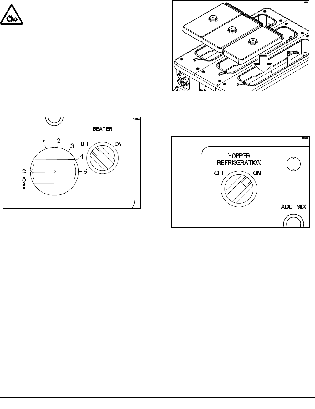
Make sure the refrigeration switch and the hopper
refrigeration switch are in the “OFF” position.
Figure 22
IMPORTANT! Refrigeration should NOT be on
when water is present in the freezing cylinder or
hopper.
19
Model C043 Operating Procedures
Step 7
Place an empty mix pail under the draw arm plate (if
the machine is not equipped with a trough).
Figure 23
Step 8
Pour the sanitizing solution into the hopper.
Figure 24
Step 9
Brush clean the mix hopper.
Figure 25
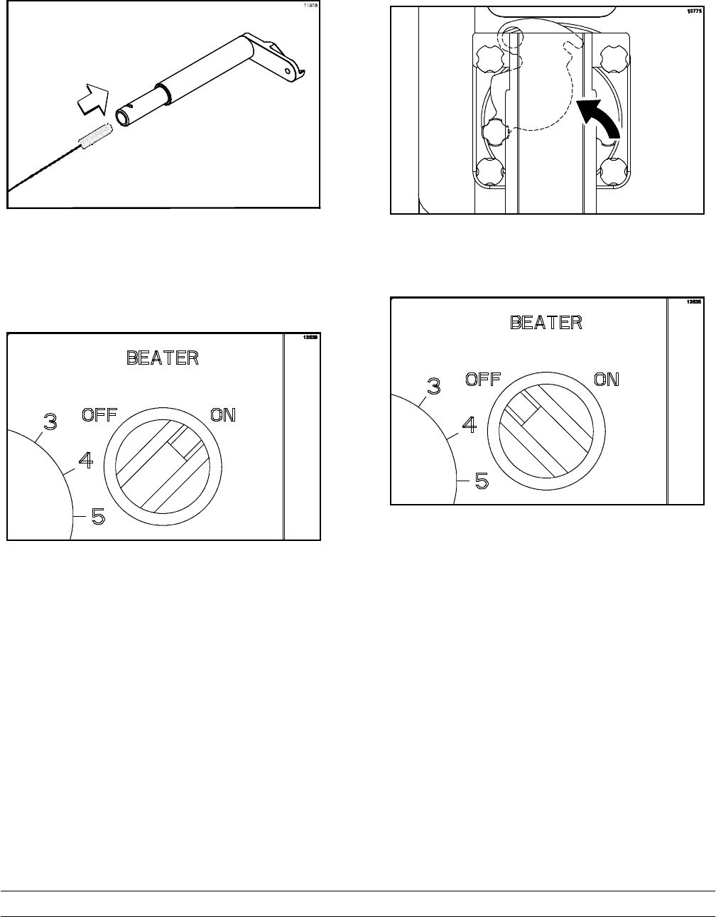
Step 10
Place the beater switch in the ON position and set
the timer for five minutes.
Figure 26
Step 11
After five minutes have elapsed, open the draw arm
plate and drain the sanitizer into the empty mix pail.
Note: If your machine is equipped with a trough,
drain the sanitizer into the trough.
Step 12
Place the beater switch in the “OFF” position and
the flow adjustment knob in the “CLOSE” position.
Figure 27
20 Model C043Operating Procedures
IMPORTANT! Your hands must be clean
and sanitized before proceeding with the next
steps.
Step 13
Remove the splash guards from the doors.
Figure 28
Step 14
Remove the chute from the hopper.
Figure 29
Step 15
Install the feed tube assembly into the mix inlet hole
located at the bottom of the hopper. Make sure the
feed tube is completely seated in the mix inlet hole.
Figure 30
Step 16
Place one end of the flow control rod into the hole
located on the feed tube. Place the other end of the
rod into the hole on the front flow control lever.
Figure 31
Step 17
Discard the sanitizer.
Repeat these steps for the remaining freezing
cylinders.
21
Model C043 Operating Procedures
Priming - Custard
KEEP FINGERS OUT OF FILL AND
DISCHARGE OPENINGS! Failure to do so may
result in severe personal injury, contaminated
product, or component damage.
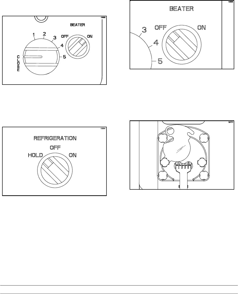
Step 1
IMPORTANT: Verify that the flow adjustment knob
is in the “CLOSE” position and the beater motor
switch is in the “OFF” position. The draw arm plate
must be closed.
Figure 32
Note: The flow adjustment knob is used to adjust
the flow of mix. Turning the adjustment knob
clockwise increases the flow. A counter-clockwise
turn decreases the flow. Adjust the mix flow as
needed to maintain proper product consistency.
Step 2
On the front half of the hoppers, install the hopper
covers that have the raised lip.
Figure 33
Step 3
Place the hopper refrigeration knob in the “ON”
position and set the timer for 30 minutes.
Figure 34
Step 4
After 30 minutes have expired, fill the hopper with
fresh mix.
Note: Use only FRESH MIX when priming the
freezer.
22 Model C043Operating Procedures
120213
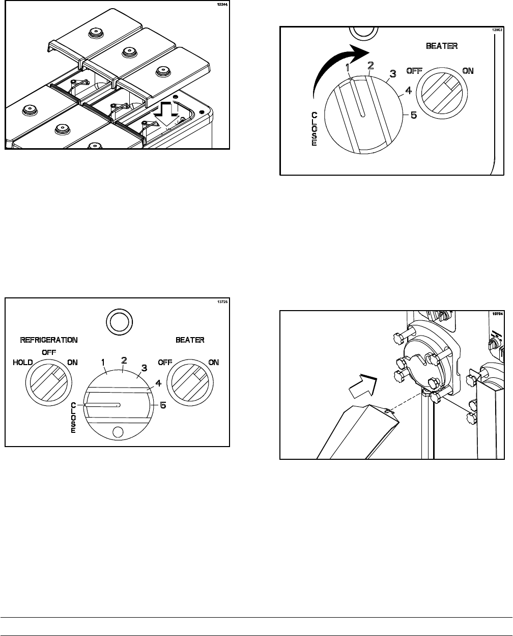
Step 5
On the back half of the hoppers, install the hopper
covers that have the concave lip. For maximum
capacity, the hopper should be full.
Figure 35
Step 6
Place the beater switch and the refrigeration switch
in the “ON” position. Set the timer for one minute.
Note: The refrigeration switch will not activate
unless the beater switch is on.
Figure 36
Step 7
After one minute has expired, turn the flow
adjustment knob to “1” and set the timer for three
minutes.
Note: Whenever an adjustment is made, first turn
the adjustment knob all the way to “5” and then back
to the desired number.
Figure 37
Step 8
After three minutes have expired, open the draw
arm plate. If the custard is too soft, close the draw
arm plate and wait one minute. Repeat until the
custard looks servable.
Step 9
Close the draw arm plate. Using sanitized hands,
install a sanitized product chute.
Figure 38
23
Model C043 Operating Procedures
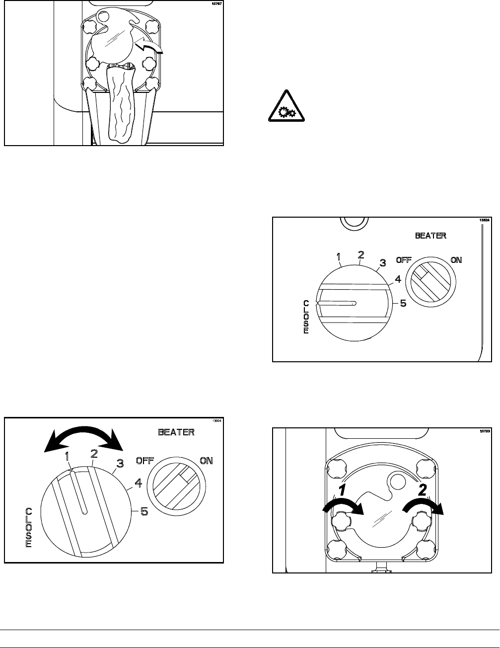
Step 10
Open the draw arm plate.
Figure 39
Note: A chattering noise indicates that not enough
mix is entering the freezing cylinder. It may be
necessary to increase the flow of mix into the
freezing cylinder. Increase the flow control knob only
1/2 a number at a time.It takes 3 - 5 minutes to see
the results of the adjustment. (Whenever an
adjustment is made, first turn the adjustment knob
all the way to “5” and then back to the desired
number.)
Step 11
Continue to run the frozen custard into the holding
cabinet until the desired amount is obtained. Adjust
the mix flow as needed to maintain proper product
consistency. For maximum capacity, make sure the
hopper is full and the flow is adjusted as high as
possible within the acceptable product temperature
range.
Figure 40
Step 12
When the desired amount is obtained and more
custard will be made later, follow the “Hold Cycle
During Operation” instructions starting on page 26.
Step 13
Repeat these steps for the remaining freezing
cylinders.
Priming - Lemon Ice
KEEP FINGERS OUT OF FILL AND
DISCHARGE OPENINGS! Failure to do so may
result in severe personal injury, contaminated
product, or component damage.
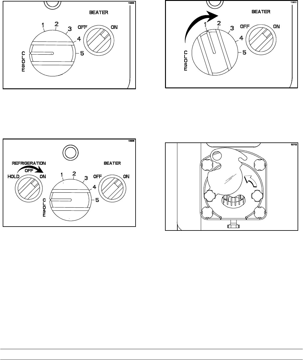
Step 1
Verify that the flow adjustment knob is in the
“CLOSE” position and the beater motor switch is in
the “OFF” position.
Figure 41
Step 2
Close the draw arm plate. Make sure the left stud
nut is snug and then the right stud nut.
Figure 42
24 Model C043Operating Procedures
120213
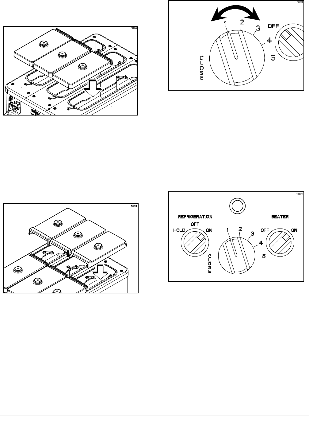
Step 3
On the front half of the hoppers, install the hopper
covers that have the raised lip.
Figure 43
Step 4
Fill the hopper with lemon ice mixture.
Note: Use only FRESH MIX when priming the
freezer.
Step 5
On the back half of the hoppers, install the hopper
covers that have the concave lip. For maximum
capacity, the hopper should be full.
Figure 44
Step 6
Turn the flow adjustment knob to “1” and set the
timer for one minute.
Note: Whenever adjustments are made, always
turn the adjustment knob all the way to “5” and then
back to the desired number.
Figure 45
Step 7
After one minute has expired, place the beater and
refrigeration switches in the ON position and set the
timer for three minutes.
Figure 46
Step 8
After three minutes have expired, open the draw
arm plate to check for proper frozen lemon ice
consistency. If the lemon ice is too soft, close the
draw arm plate for 20 to 30 seconds and repeat.
25
Model C043 Operating Procedures
Note: If lemon ice does not dispense, use the rake
to clean the draw arm plate area.
Figure 47
Step 9
When frozen lemon ice appears, close the draw arm
plate. Using sanitized hands, install a sanitized
product chute.
Figure 48
Step 10
Open the draw arm plate and secure it in place.
Figure 49
Step 11
Continue to run the frozen lemon ice into the holding
cabinet until the desired amount is obtained. Adjust
the mix flow as needed to maintain proper product
consistency. Turn the flow adjustment knob
clockwise if the product is too firm and
counter-clockwise if the product is too soft.
Figure 50
Step 12
Place the lemon ice freezing cylinder refrigeration
switch in the “OFF” position between runs. If a
changeover to another flavor or product is desired,
refer to the “Preparing for Shutdown” section of
this manual on page 29.
Figure 51
26 Model C043Operating Procedures
Hold Cycle During Operation
The HOLD cycle is only used for custard, NOT
lemon ice.
Step 1
Place the flow adjustment knob in the “CLOSE”
position. Set the timer for one minute.
Figure 52
Step 2
After one minute has expired, place the refrigeration
switch in the “HOLD” position for custard.
Note: The HOLD cycle is not used for lemon ice.
Figure 53
Step 3
When the frozen custard stops flowing,
(takes approximately two minutes) place the beater
motor switch in the “OFF” position.
Figure 54
Step 4
Use the rake to remove as much custard from the
product door as possible.
Figure 55
27
Model C043 Operating Procedures
Step 5
Close the draw arm plate. Make sure the left stud
nut is snug and then the right stud nut.
Figure 56
Step 6
Remove the custard chute and take it to the sink for
cleaning and sanitizing.
Figure 57
Step 7
Close the dipping cabinet cover.
Step 8
Prepare a squeeze bottle of approved 100 PPM
sanitizing solution. Squeeze the sanitizing solution
around the draw arm plate and stud nuts to remove
any left-over product. If necessary, brush clean the
area with the door spout brush and rinse with the
sanitizing solution.
Figure 58
Step 9
Repeat these steps for the remaining freezing
cylinders.
28 Model C043Operating Procedures
120213
Resuming Production During
Operation
Step 1
Place the beater switch in the “ON” position.
Figure 59
Step 2
Place the refrigeration switch in the “ON” position.
Figure 60
Step 3
Set the timer for one minute. After the minute
expires, open the flow control assembly to “1” and
set the timer for three minutes.
Note: Whenever an adjustment is made, first turn
the adjustment knob all the way to “5” and then back
to the desired number.
Figure 61
Step 4
After three minutes have expired, open the draw
arm plate. If the custard is too soft, close the draw
arm plate and wait one minute. Repeat as
necessary.
Figure 62
29
Model C043 Operating Procedures
Step 5
When custard appears, adjust the flow adjustment
knob to gain the desired custard texture. Turn the flow
adjustment knob clockwise if the product is too firm
and counter-clockwise if the product is too soft.
Figure 63
Step 6
When the product looks servable, close the draw
arm plate. Using sanitized hands,installa
sanitized custard chute.
Figure 64
Step 7
Open the draw arm plate. Continue to run the frozen
custard into the holding cabinet until the desired
amount is obtained. Adjust the mix flow as needed
to maintain proper product consistency. When the
desired amount is obtained and more custard will be
made later, follow the “Hold Cycle During
Operation” instructions starting on page 26.
Figure 65
Preparing for Shutdown
Perform the following procedures to remove the
remaining custard in the freezing cylinder when
there is mix in the hopper.
Step 1
Place the refrigeration switch in the “OFF” position.
Figure 66
Step 2
Set the timer for 20 minutes. This allows the freezing
cylinder enough time to warm before removing the
remaining custard.
30 Model C043Operating Procedures
Step 3
Place the beater switch in the “ON” position.
Figure 67
Step 4
Open the dipping cabinet cover. Close the draw arm
plate. Using sanitized hands, install a sanitized
custard chute.
Figure 68
Step 5
Open the draw arm plate and turn the flow
adjustment knob to “5”. Run the remaining mix
through the freezing cylinder and properly dispose of
the mix.
Figure 69
Note: If local health codes permit the use of
rerun, place a sanitized, NSF approved rerun
container beneath the opening of the front plate and
run the remaining mix into the container. See
page 39 for instructions regarding the proper use of
rerun.
Step 6
After all the custard has drained from the hopper,
remove the hopper cover, the flow control rod and
the feed tube.
Figure 70
Step 7
Repeat these steps for the remaining freezing
cylinders.
31
Model C043 Operating Procedures
Rinsing
Step 1
Place the hopper refrigeration switch in the “OFF”
position.
Figure 71
Step 2
Make sure the refrigeration switch is in the “OFF”
position.
Figure 72
Step 3
Close the draw arm plate and remove the product
chute.
Figure 73
Step 4
Install the splash guard.
Figure 74
Step 5
With a pail beneath the draw arm plate, pour four
gallons (15 liters) of cool, clean water into the
hopper. (Note: Use the faucet if the machine is
equipped with one.)
Figure 75
32 Model C043Operating Procedures
Step 6
With the brushes provided, scrub the mix hopper.
Figure 76
Step 7
Place the beater switch in the “ON” position.
Figure 77
Step 8
Open the draw plate and drain the rinse water from
the freezing cylinder.
Figure 78
Step 9
Repeat this procedure until all mix residue is gone
and the water is clear.
Step 10
Place the beater switch in the “OFF” position.
Figure 79
Step 11
Repeat these steps for the remaining freezing
cylinders.
33
Model C043 Operating Procedures
Cleaning
IMPORTANT: Failure to follow these
cleaning procedures may result in bacterial
contamination of the frozen custard product.
Step 1
Make sure the refrigeration switch is in the “OFF”
position.
Figure 80
Step 2
Close the draw arm plate.
Figure 81
Step 3
Using lukewarm water, prepare an approved 100
PPM sanitizing solution (examples: 5 gal. [19 liters]
of Kay-5Ror 4 gal. [15 liters] of Stera-SheenR).
USE WARM WATER AND FOLLOW THE
MANUFACTURER'S SPECIFICATIONS.
Step 4
Pour the cleaning solution into the hopper. Brush
clean the sides and bottom of the hopper.
Figure 82
Step 5
MAKE SURE THE BEATER SWITCH IS
IN THE “OFF” POSITION.
Figure 83
Step 6
Using the draw valve brush (1” x 2” x 17”), clean the
mix inlet hole.
Figure 84
34 Model C043Operating Procedures
Step 7
Using the double-ended brush, clean the inside of
the feed tube.
Figure 85
Step 8
Place the beater switch in the “ON” position. Set the
timer for five minutes.
Figure 86
Step 9
After five minutes has elapsed, open the draw arm
plate and drain all the solution from the freezing
cylinder.
Figure 87
Step 10
Place the beater switch in the “OFF” position.
Figure 88
Step 11
Repeat these steps for each freezing cylinder.
35
Model C043 Operating Procedures
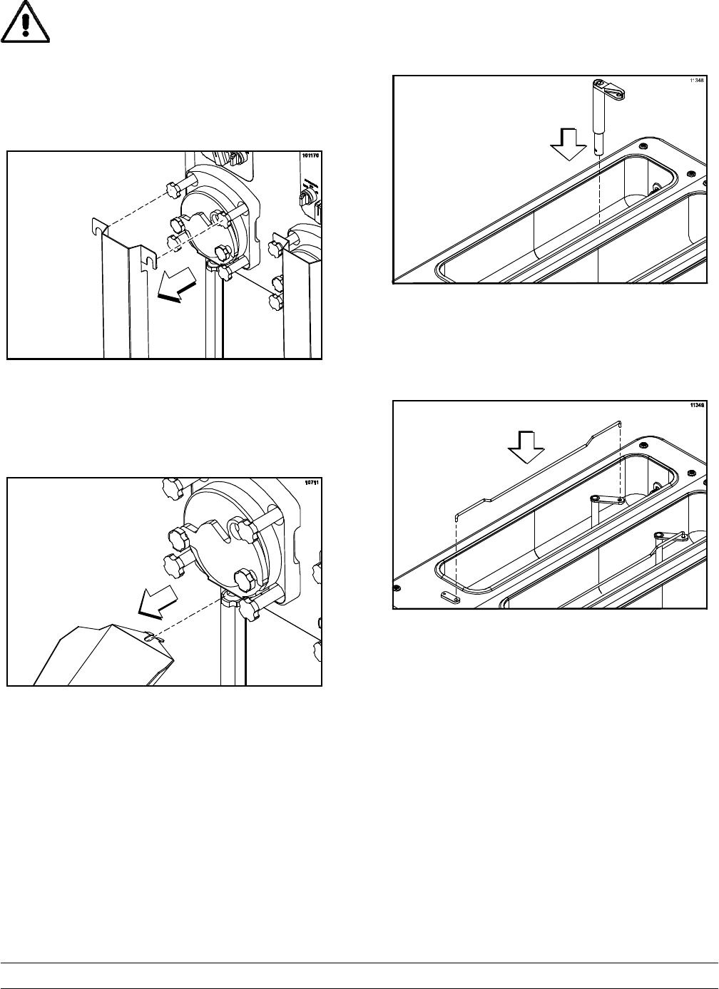
Disassembly
Step 1
Remove the door assembly.
Figure 89
Step 2
Disassemble the door assembly. Remove the gasket
from the product door.
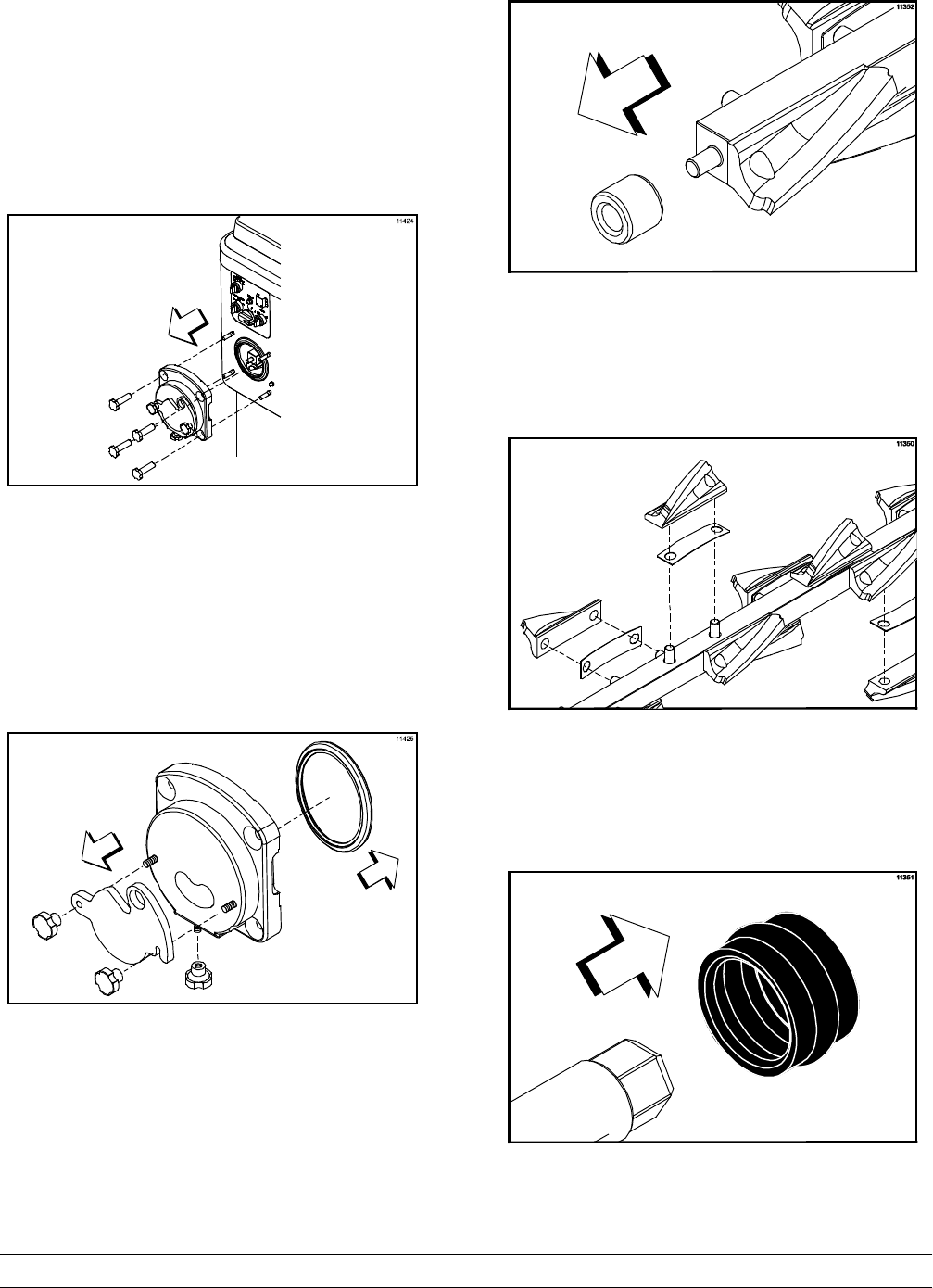
Figure 90
Step 3
Remove the front bearing from the door or beater
shaft.
Figure 91
Step 4
While removing the beater shaft, take each blade
and leaf spring off and place them in a container for
cleaning.
Figure 92
Step 5
Remove the rear seal from the beater shaft. Use a
single-use towel to remove the lubricant from the
seal before taking it to the sink for cleaning.
Figure 93
36 Model C043Operating Procedures
Note: If the rear seal remains in the drive coupling
at the back of the machine instead of coming out
with the beater shaft, perform the following:
SReinstall three blades and leaf springs on
the beater shaft.
SSlide the beater shaft back into the freezing
cylinder until the hex end is firmly engaged
in the drive coupling.
SRemove the beater shaft by pulling it
straight out.
SRepeat as necessary until the rear seal is
removed.
Step 6
Remove the hopper covers, the feed tube and the
flow control rod.
Figure 94
Step 7
Take all the parts to the sink for complete
disassembly and brush cleaning.
Step 8
Repeat these steps for each freezing cylinder.
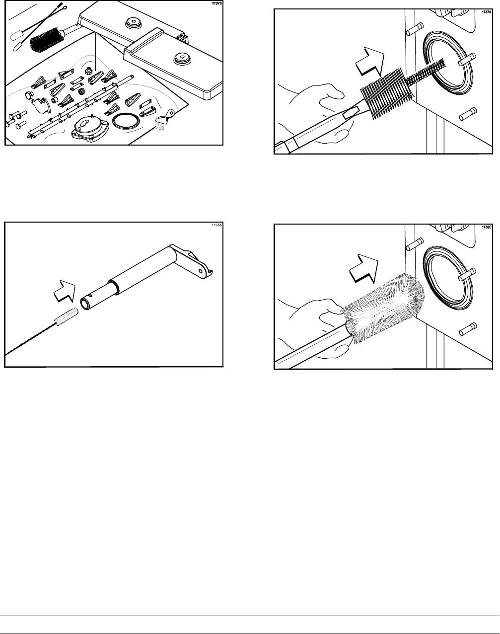
Brush Cleaning
IMPORTANT: Failure to follow these
cleaning procedures may result in bacterial
contamination of the frozen custard product.
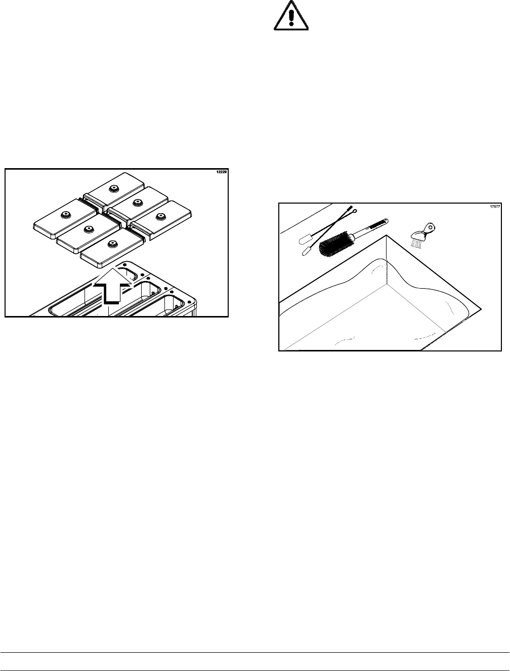
Step 1
Prepare a sink with an approved cleaning solution
(examples: Kay-5® or Stera-Sheen®). USE
WARM WATER AND FOLLOW THE MANUFAC-
TURER'S SPECIFICATIONS. If another approved
cleaner is used, dilute it according to the label
instructions. (IMPORTANT: Follow the label direc-
tions. Too STRONG of a solution can cause parts
damage, while too MILD of a solution will not provide
adequate cleaning.)
Figure 95
Make sure all brushes provided with the freezer are
available for brush cleaning.
37
Model C043 Operating Procedures
Step 2
Thoroughly brush clean all disassembled parts in the
cleaning solution, making sure all lubricant and mix
film is removed.
Figure 96
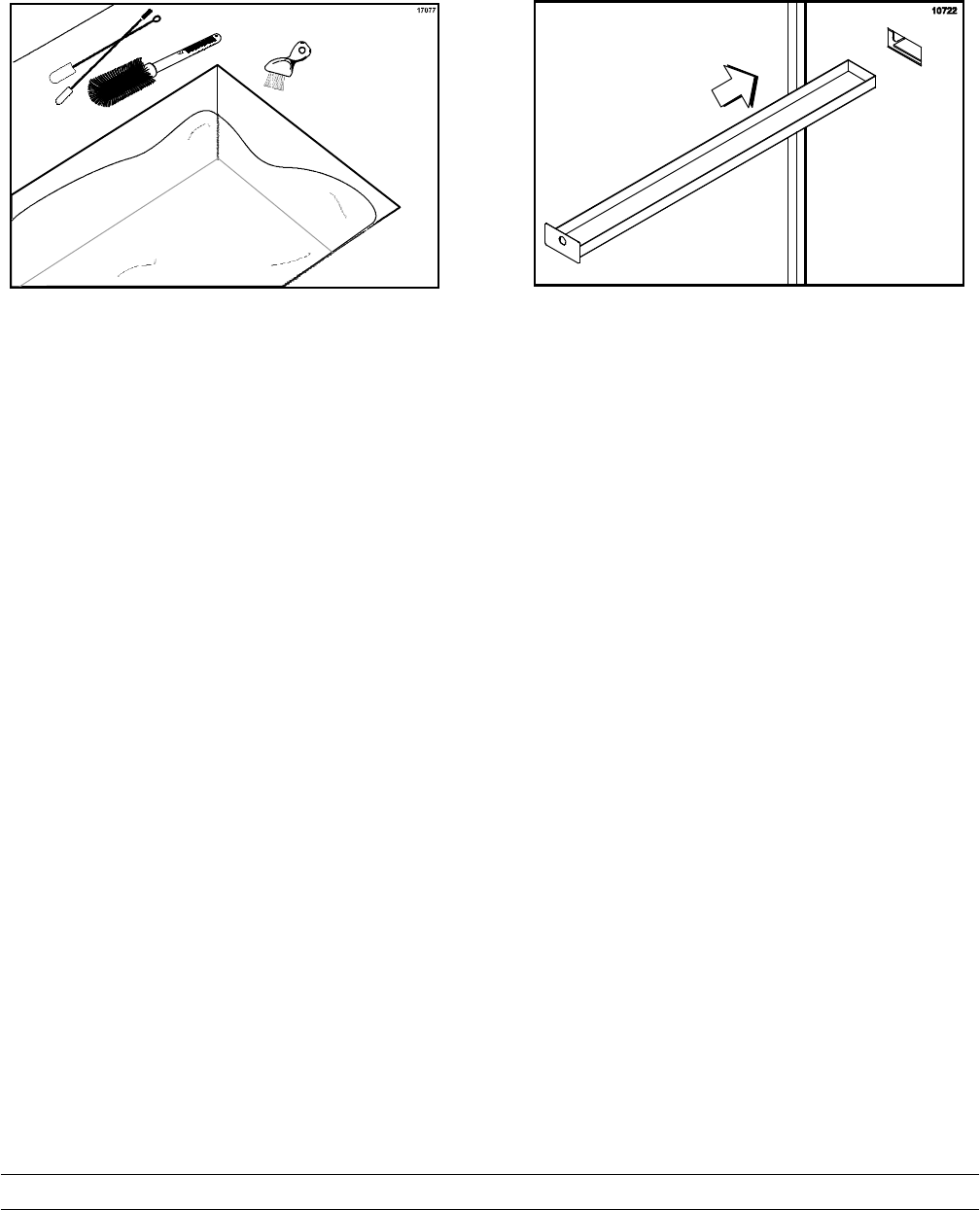
Step 3
Use the double-ended brush to clean the inside of
the feed tube.
Figure 97
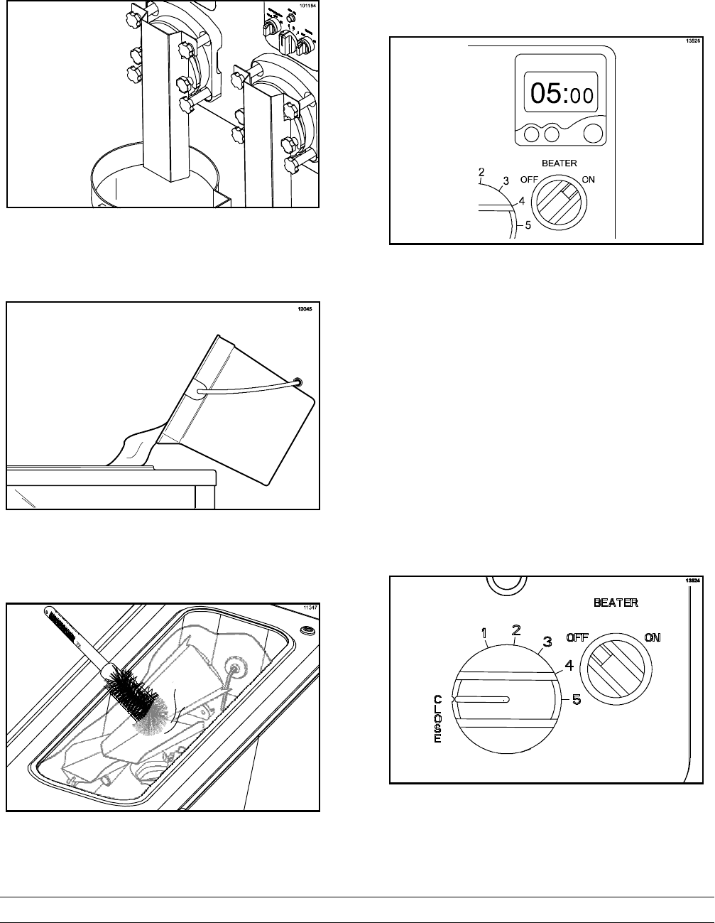
Step 4
Return to the freezer with a small amount of
cleaning solution. Brush clean the rear shell bearing
at the back of each freezing cylinder with the black
bristle brush.
Figure 98
Step 5
Brush clean the freezing cylinder with the long white
brush.
Figure 99
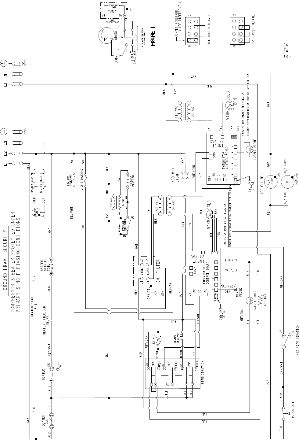
38 Model C043Operating Procedures
Step 6
Prepare a sink with an approved sanitizing solution
(examples: Kay-5® or Stera-Sheen®). USE
WARM WATER AND FOLLOW THE MANUFAC-
TURER'S SPECIFICATIONS.
Figure 100
Step 7
Repeat Step 2 using the sanitizing solution.
Step 8
Place all cleaned parts on a clean, dry surface to air
dry overnight.
Step 9
Empty, clean, and reinstall the rear drip pan.
Figure 101
Step 10
Wipe clean all exterior surfaces of the freezer with a
clean, sanitized towel.

39
Model C043 Important: Operator Checklist
120802
Section 7 Important: Operator Checklist
During Cleaning and Sanitizing
ALWAYS FOLLOW LOCAL HEALTH CODES.
Cleaning and sanitizing schedules are governed
by federal, state, or local regulatory agencies,
and must be followed accordingly. If the unit
has a “Standby mode”, it must not be used in
lieu of proper cleaning and sanitizing
procedures and frequencies set forth by the
ruling health authority. The following check
points should be stressed during the cleaning
and sanitizing operations.
CLEANING AND SANITIZING MUST BE
PERFORMED DAILY.
Troubleshooting Bacterial Count
j1. Thoroughly clean and sanitize the machine
regularly, including complete disassembly and
brush cleaning.
j2. Use all brushes supplied for thorough
cleaning. The brushes are specially designed
to reach all mix passageways.
j3. Use the white bristle brush to clean the mix
inlet hole which extends from the mix hopper
down to the rear of the freezing cylinder.
j4. Use the black bristle brush to thoroughly
clean the rear shell bearing located at the rear
of the freezing cylinder. Be sure there is a
generous amount of cleaning solution on the
brush.
j5. IF LOCAL HEALTH CODES PERMIT THE
USE OF RERUN, make sure the mix rerun is
stored in a sanitized, covered stainless steel
container and used the following day. DO
NOT prime the machine with rerun. When
using rerun, skim off the foam and discard.
Mix the rerun with fresh mix in a ratio of 50/50
during the days operation.
j6. On a designated day of the week, run the mix
as low as feasible and discard it after closing.
This will break the rerun cycle and reduce the
possibility of high bacteria and coliform
counts.
j7. Properly prepare the cleaning and sanitizing
solutions. Read and follow the label directions
carefully. Too strong of a solution may
damage the parts and too weak of a solution
will not do an adequate job of cleaning or
sanitizing.
j8. The temperature of the mix in the mix hopper
and walk-in cooler should be below 40_F
(4.4_C).
Regular Maintenance Checks
j1. Replace scraper blades that are nicked or
damaged. Before installing the beater
assembly, be certain that scraper blades and
leaf springs are properly attached to the
beater shaft.
j2. Check the rear shell bearing for signs of wear
(excessive mix leakage in rear drip pan) and
be certain it is properly cleaned.
j3. Using a long brush and a cloth towel, keep
the rear shell bearing and the female hex
drive socket clean and free of lubricant and
mix deposits.
j4. Dispose of seals if they are worn, torn, or fit
too loosely, and replace with new ones.

40 Model C043Important: Operator Checklist
j5. Follow all lubricating procedures as outlined in
“Assembly”.
j6. If your machine is air cooled, check the
condenser for accumulation of dirt and lint.
Dirty condensers will reduce the efficiency
and capacity of the machine. Condensers
should be cleaned monthly with a soft brush.
Never use screwdrivers or other metal probes
to clean between the fins.
Note: For machines equipped with an air
filter, it will be necessary to vacuum clean the
filters on a monthly schedule.
Caution: Always disconnect
electrical power prior to cleaning the
condenser. Failure to follow this instruction
may result in electrocution.
j7. If your machine is water cooled, check the
water lines for kinks or leaks. Kinks can occur
when the machine is moved back and forth for
cleaning or maintenance purposes.
Deteriorated or cracked water lines should be
replaced only by an authorized Taylor
distributor.
Winter Storage
If the place of business is to be closed during the
winter months, it is important to protect the freezer
by following certain precautions, particularly if the
building is subject to freezing conditions.
Disconnect the freezer from the main power source
to prevent possible electrical damage.
On water cooled freezers, disconnect the water
supply. Relieve pressure on the spring in the water
valve. Use air pressure on the outlet side to blow out
any water remaining in the condenser. This is
extremely important. Failure to follow this
procedure may cause severe and costly damage to
the refrigeration system.
Your local Taylor Distributor can perform this winter
storage service for you.
Wrap detachable parts of the freezer such as
beater, blades, beater shaft, and freezer door, and
place them in a protected dry place. Rubber trim
parts and gaskets can be protected by wrapping
them with moisture-proof paper. All parts should be
thoroughly cleaned of dried mix or lubrication which
attract mice and other vermin.
It is recommended that an authorized service
technician perform winter storage draining, to insure
all water has been removed. This will guard against
freezing and rupturing of the components.

41
Model C043 Important: Operator Checklist
Section 8 Troubleshooting Guide
PROBLEM PROBABLE CAUSE REMEDY PAGE
REF.
1. The product is too stiff. a. Flow rate is too slow. a. Adjust the flow rate. 21
2. The scraper blades make
a chattering noise. a. Flow rate is too slow. a. Adjust the flow rate. 21
3. The product is too soft. a. Flow rate is too fast. a. Adjust the flow rate. 21
b. There is a problem with
the refrigeration system. b. Call an authorized service
technician. ---
4. The mix low indicator is
illuminated. a. Inadequate level of mix in
the mix hopper. a. Fill the mix hopper with
mix. 21
b. Bad electrical connection. b. Call an authorized service
technician. ---
5. The mix low indicator is
illuminated and the
product is too stiff.
a. The level of mix in the mix
hopper is inadequate and
the flow rate is too slow.
a. Fill the hopper with mix if
further production is
required. If no further
production is required,
open the flow control all
the way and place the
refrigeration switch in the
“OFF” position.
21 / 23
6. Beater motor won't start. a. The beater motor overload
has tripped. a. Turn the machine off.
Press the reset button and
restart the machine.
---
b. The power switch is in the
OFF position. b. Place the power switch in
the ON position. ---
c. The beater motor switch is
in the OFF position. c. Place the beater motor
switch in the ON position. ---
d. The circuit breaker is off
or the fuse is blown. d. Turn the breaker on, or
replace the fuse. ---

42 Model C043Parts Replacement Schedule
Section 9 Parts Replacement Schedule
PART DESCRIPTION EVERY 3 MONTHS EVERY 6 MONTHS ANNUALLY
BRUSH-DBL END-PUMP & FEED INSPECT & REPLACE IF NECESSARY MINIMUM
BRUSH-DRAW VALVE 1”OD X 2”X17” INSPECT & REPLACE IF NECESSARY MINIMUM
BRUSH-BARREL INSPECT & REPLACE IF NECESSARY MINIMUM
BRUSH-REAR BRG INSPECT & REPLACE IF NECESSARY MINIMUM
BRUSH-MIX PUMP BODY 3”X7” INSPECT & REPLACE IF NECESSARY MINIMUM
BRUSH-END-DOOR-SPOUT-SS INSPECT & REPLACE IF NECESSARY MINIMUM
GASKET-DOOR X
BEARING-DOOR-FRONT X
SEAL-DRIVE SHAFT X

43
Model C043 Warranty Explanation
Section 10 Warranty Explanation
Class 103 Parts
The warranty for new equipment Class 103 parts is
one year from the original date of unit installation,
with a replacement parts warranty of three months.
Class 212 Parts
The warranty for new equipment Class 212 parts is
two years from the original date of unit installation,
with a replacement parts warranty of twelve months.
Class 512 Parts
The warranty for new equipment Class 512 parts is
five years from the original date of unit installation,
with a replacement parts warranty of twelve months.
Class 000 Parts
Class 000 parts are considered wear items - no
warranty.
Class *** Parts
See warranty explanation on the back of the
check-out card.
CAUTION: Warranty is valid only if the parts are authorized Taylor parts, purchased from an authorized
Taylor Distributor, and the required service work is provided by an authorized Taylor service technician.
Taylor reserves the right to deny warranty claims on equipment or parts if non-approved parts or refrigerant
were installed in the machine, system modifications were performed beyond factory recommendations, or
it is determined that the failure was caused by neglect or abuse.

Section 11 Parts List
44
Parts List Model C043
C043 Parts List
DESCRIPTION PART
NUMBER C043
QTY. WARR.
CLASS REMARKS
BEARING-DOOR-FRONT *C043* 064315 3000
BEARING-REAR SHELL-NICKEL 031324 3000
+NUT-BEARING 028991 3000
+WASHER-BEARING LOCK 012864 3000
BELT-AX41 023876 6000
BLADE-SCRAPER 30 PITCH 063656 33 000
BLADE-SCRAPER-REAR 30 PITCH 063640 3000
SPRING-DASHER BLADE *C043* 063693 36 000
BLOCK-TERMINAL 5P 20A, 300V 024329 3103
BLOCK-TERMINAL 2P L1,N 039421 1103
BLOCK-TERMINAL 3P L1,L2,L3 039423 3103
BLOCK-TERMINAL 2P .25 SPADE 051644 3103
BRUSH-BARREL-CUSTARD 063843 1000 COMPLETE WITH HANDLE
+BRUSH-BARREL-CUSTARD 063843-1 1000 NO HANDLE
BRUSH-DBL END-PUMP & FEED TUBE 013072 1000
BRUSH-DRAW VALVE 1"OD X 2"X17" 013073 1000
BRUSH-END-DOOR-SPOUT-SS-HT 039719 1000
BRUSH-MIX PUMP BODY-3" X 7" WH 023316 1000
BRUSH-REAR BRG CUSTARD 063844 1000 COMPLETE WITH HANDLE
+BRUSH-REAR BRG CUSTARD 063844-1 1000 NO HANDLE
BUSHING-.235ID X .490L *CO43* 064278 6000 COVER
BUSHING-RUBBER MOUNT 012258 6103
BUSHING-SNAP 11/16 ID X 7/8OD 010548 3103
CAP-RUBBER MOUNT 011844 6103
CASTER-4" SWV 3/4-10 STM 044106 4103
CHUTE-LONG *C043* 063619 1103
CHUTE-SHORT *CUSTARD* 063618 3103
CLIP-PANEL-SIDE *C043* 065490 6000
COMPRESSOR AEA9415ZXA-AE570AT 063041-12 1512
+SLEEVE-MOUNTING-COMP-AE 039920 4000
+GROMMET-COMPRESSOR MOUNT-AE-AK 039919 4000
CONDENSER-AC 14LX8H-3ROW 058762 1103
CONTROL-THERMISTOR-MIX LVL X63019-SER 3103
Model C043

45
Model C043 Parts List
DESCRIPTION REMARKSWARR.
CLASS
C043
QTY.
PART
NUMBER
CONTROL-THERMISTOR X63020-SER 1103
COUPLING A.UNIVERSAL JOINT X64956 3103
+PIN-ROLL-3/32X9/16 STEEL PLAIN 015971 12 103
COUPLING-3/8FS X 1/4FS 031791 1103 LINE A.-DISCHARGE *AUX*C043*
COVER A.-MIX CAN FRT *C043* X63682 3103
COVER A.-PANEL-SIDE *C043* X65637 1103
COVER A.-*C043* X63700-SP 2103
COVER A.-LEFT *C043* X63704 1103
COVER A.-HOPPER-REAR *C043* 065700 3103
COVER A.-HOPPER-FRONT *C043* 065701 3103
CORD-POWER 063862-12 1000
COVER-CONTROL BOX *C043* 063635 3103
COVER-VALVE-SHUT OFF *C043* 063622 3103
DECAL-DEC-TAYLOR 021872 1000
DECAL-INSTR-CLN-MAN-C043 065871 1000
DECAL-TROUBLESHOOT 038374 1000
DEFLECTOR-SPLASH *C043* 063628 3103
DOOR A.-*C043*PARTIAL X63611-SER 3103 DOOR W/GUARD PINS, MAGNET, PLUG, STUD
+BEARING-DOOR-FRONT *C043* 064315 3000
+GASKET-DOOR HT 4"-DOUBLE 048926 3000
+INTERLOCK A.-DOOR *C043* X65657 3103
+NUT-STUD *345-346-349-355* 043666 9103
+PLATE-DRAW ARM *C043* 063614 3103
+STUD-DRAW ARM *C043* 063617 9103
DIAGRAM-WIRING *C043* 063943-33A 1000
DIAGRAM-WIRING *C043* 063943-33B 2000
DRYER-CAP. TUBE-HP62/R134A 047696 1000 LINE-LIQUID *AUX*C043*
DRYER-FILTER-HP62-3/8 X 1/4S 048901 3000
E-RING 1/4 BLACK PHOS 032190 6000 FLOW REG LEVER
EYELET-RESET BUTTON 013739 6103
FAN-6 BLADE 9.5" 057244 1103
FASTENER-CLIP 1/4-20 U-TYPE 045865 4000
FILTER-CORCOM 2VR1 032567 3103
FITTING A.-EVAP INLET*C043* X67059 3103
FITTING-INLET-SHELL 1/2 CU 066906 3103
Model C043

46
Parts List Model C043
DESCRIPTION REMARKSWARR.
CLASS
C043
QTY.
PART
NUMBER
GASKET-CONTROL COVER *C043* 063653 3000
GASKET-DOOR HT 4"-DOUBLE 048926 3000
GEAR A.*REDUCER 4.21:1 044172 3212 X66340 ALIGNMENT TOOL
GROMMET-7/16 X 5/16 SHOCK ABSB 016212 6000
HANDLE-STNLS FLUSH PULL 019043 4103 PANELS
+NUT-10-32 WHIZ FLANGE LOCKNUT 020983 8000 PANEL HANDLES
HARNESS-WIRE *CO43*CNTRL BOX 064224 3103
HARNESS-WIRE *CO43*COVER ASSY 064226 3103 FRONT ROTARY SWITCH
HARNESS-WIRE *CO43*BTR MOTOR 064227 3103
HARNESS-WIRE *CO43*AUX REFRIG 064228 1103
HARNESS-WIRE *CO43*REFRIG SOL 064229 3103
HARNESS-WIRE*C043*THERM PRB 066290 3103 W/RESISTOR-1/4W 5% 33K OHMS
HARNESS-WIRE *CO43*THERM PRB 064230 3103
HARNESS-WIRE *CO43*DOOR INTLK 064231 3103
HINGE A.-MOTOR X25703 3103
HOOD A.-MIX CAN *C043* X63606 1103
HUB-5/8 BORE SPLIT 027815 3103
INTERLOCK A.-DOOR *C043* X65657 3103 SEE DOOR
SWITCH-REED*DOOR INTERLOCK*6 056249 3103
SPRING-INTERLOCK DOOR 065409 3000
KIT A.-TUNE UP*C043* X64743 1000
BEARING-DOOR-FRONT *C043* 064315 3000
GASKET-DOOR HT 4"-DOUBLE 048926 3000
SEAL-DRIVE SHAFT 032560 3000
KNOB A.-FLOW REGULATOR *C043* X63658 3000
SCREW-10-32X3/4 SOCKET SET S 065907 6000
LABEL-3PH MTR PROT/1PH C-ENG/S 025949 1000
LABEL-ATTN SVC ENG 015068 2000
LABEL-CAUTION-GRD-PERM-ENG/SP 032164 1000
LABEL-DOOR-MOVE PART 032749 2000
LABEL-WARN-COVER 051433 7000
LEG-8" 2"OD-3/4-10 STUD-HEX FT 044652 4103
LEVER A.-FLOW REG *C043* X64316 3103
LIGHT-ORANGE-ROUND 017450 3103 ADD MIX
LINE-EVAP OUT *AUX*C043* 063891 2103 COVER A.-MIX CAN FRT *C043*
Model C043

47
Model C043 Parts List
DESCRIPTION REMARKSWARR.
CLASS
C043
QTY.
PART
NUMBER
+ARMAFLEX 3/8 ID X 1/4WALL 020896-12 2NNN R50322
LUBRICANT-TAYLOR 4 OZ. 047518 1000
MAN-OPER C043 068359-M 1000
MOTOR-2.0 HP 017650-33 3212
MOTOR-FAN 16 WATT 063687-12 1103
MANIFOLD-3/8S THRU-1/4S OUT-2 046922 1103 LINE A.-DISCHARGE *AUX*C043*
NUT-STUD *345-346-349-355* 043666 9103 DOOR
NUT-STUD *460-664-754-56*SHORT 034383 12 103
PANEL A.-FRONT LOWER *C043* X63718 1103
PANEL A.-FRONT-UPPER *C043* X63694 1103
PANEL A.-REAR *C043* X63715 1103
PANEL A.-SIDE LEFT *C043* X63724 1103
PANEL A.-SIDE RIGHT *C043* X63720 1103
PULLEY-2AK28-7/8 010294 3103
PULLEY-2AK84H 009759 3103
PLUG-HOLE 7/8 DIA. BLACK 010077 1000 FAUCET OPENING
PROBEA.-MIXLOW-HT X42077 3103 MIX CAN
+DISC-PROBE *SQ HOLE* 030965 3103
+SPACER-PROBE *SQ HOLE* 030966 3103
+NUT-10-32 HEX MACHINE SCREW 005598 6000
PROBE-THERMISTOR-BARREL-2% TOL 038061-BLK 4103
RAKE-FINGER GUARD *C043* 064888 1103 K6110000 & UP
RELAY-DPDT-24VAC-30A@277V 054703-03 3103
ROD-FLOW CONTROL 063593 3103
ROD-MIX CAN SUPPORT *C043* 063661 4103
SANITIZER-STERA SHEEN -GREEN 055492 1000 100/2OZ. PACKETS/CS
SANITIZER-STERA SHEEN-GREEN 010425 1000 64 OZ JAR
SCREW-SHOULDER 3/8X5/8 BOLT 037361 2000
SEAL-CLAMP-CIP 1"DIA. TUBE 063634 3000
SHAFT A.-DASHER *C043* X63689 3103
+SEAL-DRIVE SHAFT 032560 3000
+SPRING-DASHER BLADE *C043* 063693 36 000
SHAFT-FLOW REG LOWER *C043* 064279 3103
+BUSHING-.235ID X .490L *CO43* 064278 3000
+WASHER-3/8 EXTERNAL TOOTH LOCK 001087 3000
Model C043

48
Parts List Model C043
DESCRIPTION REMARKSWARR.
CLASS
C043
QTY.
PART
NUMBER
+NUT-JAM 3/8-24 ZP 070756 3000
+E-RING 1/4 BLACK PHOS 032190 3000
SHELL A.-INSULATED *C043* X63600-SER 3512
WASHER-BEARING LOCK 012864 3000
NUT-BRASS BEARING 028991 3000
GUIDE-DRIP SEAL 028992 3000
BEARING-REAR SHELL-NICKEL 031324 3000
SHROUD-FAN *C043* 066447 1103 S/N K8050000 & UP
SHROUD-FAN *C043* 063624 1103
SPRING-COMP.970X.115X2.00 025707 6103
STARTER-3 PHASE 4 TO 6.5 AMP 066794-33J 3103
+OVERLOAD-THERMAL-3P-4.0/6.5A 067461-3J 103
STRAINER-CONE MESH 1/2 ODF 062299 3000 LINE A.-VAL.SHUTOFF/SUCTON-SOL
STOP-COVER *C043* 063698 12 103
STUD-NOSE CONE-3/8-16 065256 12 103
+NUT-STUD *460-664-754-56*SH 034383 12 103
SWITCH-PRESSURE 440 PSI-SOLDER 048230 1103 LINE A.-DISCHARGE *AUX*C043*
SWITCH-ROTARY OFF-ON 063702 4103
SWITCH-ROTARY ON-OFF-ON 063703 3103
TIMER-COUNTDOWN-DIGITAL *C043* 065425 1103
TOOL-DASHER SHAFT REMOVE*CO43* 063623 1103
TRANS.-240V PR1/24V SEC 10 VA 030132-27 6103
TRANS.-CONT.-ANTICIPATOR 20 VA 016352-12 1103
TRAY A.-DRIP *C043* X63636 1103
TRIM-CORNER-FRONT LEFT *C043* 063714 1103
TRIM-CORNER-FRONT R. *CUSTARD* 063711 1103
TRIM-CORNER-REAR *C043* 063712 2103
+SPACER-TRIM-CORNER *C043* 065355 32 000 CORNER TRIM
TUBE A.-FEED PLASTIC *C043* X67453 3103
VALVE-ACCESS 1/4FL X 1/4SOLDER 044404 1103 LINE A.-SUCTION *C043*
VALVE-ACCESS-1/4MFL X 3/8ODSDR 053565 2103 LINE A.-DISCHARGE & CHARGE *AUX*C043*
+CAP-VALVE-ACCESS 13/16 HEX 054519 2000
+CAP-VALVE-ACCESS 9/16 HEX 054518 2000
VALVE-CONTROL-PRESSUR-HEAD-ORI 063849 3103
+BOOT-INSULATING-EPR 062048 3000
Model C043

49
Model C043 Parts List
DESCRIPTION REMARKSWARR.
CLASS
C043
QTY.
PART
NUMBER
VALVE-EPR 1/4S 022665 1103 LINE A.-SUCTION *C043*
VALVE-EXP-THERMO-3/8 X 1/2 ODF 066904 3103
VALVE-SHUTOFF-3/8 ODF 063918 3103 LINE-A.-LIQ.INLET VALVE *C043*
VALVE-SHUTOFF-7/8 ODF 063947 3103 LINE-A.VAL.SHUTOFF/SUCTION-SOL
VALVE-SOLENOID 7/16 ORF 5/8ODF 048626-27 3103 LINE-A.VAL.SHUTOFF/SUCTION-SOL
VALVE-SOLENOID 7/64ORF X 1/4S 043449-27 3103
VARISTOR A.-SLEEVE TERMINAL X31547 4103
AVAILABLE FOR SERVICE
TOOL A.-ALIGNMENT X66340 1103
Model C043

50
Parts List Model C043
RC35 Parts List
DESCRIPTION PART
NUMBER RC35
QTY. WARR.
CLASS REMARKS
BLOCK-TERMINAL 3P L1,L2,L3 039423 1103
CAP-DUST-BULKHEAD COUPLING 048427 2000
BOOT-INSULATING-EPR 062048 1000
BOOT-INSULATING-DUAL PRESS SW 068022 1000
BOOT-INSULATING-FAN PRESS SW 068023 1000
CARD-CHECKOUT *RC25* 050197 1000
COMPRESSOR L63A183DBDA-40W CCH 048741-33H 1512 S/N K9091780 & UP
+GROMMET-COMPRESSOR MOUNTING 037428 4000
+NUT-5/16-18 WHIZ FLANGE NUT 017327 4000 COMPRESSOR
+SCREW-5/16-18X2-1/4 HEX HEAD 019267 4NNN COMPRESSOR
+SLEEVE-MOUNTING-COMP. 039924 4000
+WASHER-5/16 USS FLAT CR3 000651 4000 COMPRESSOR
COMPRESSOR L63A183DBDA 048741-33 1512 S/N K9091779 & PRIOR
HEATER-COMPRESSOR CRANKCASE 049518 1103 S/N K9091779 & PRIOR
CONDENSER-AC 20X18X2.6 3 ROW 064451 1103
+NUT-1/4-20 WHIZ FLANGE LOCK 017523 4000 CONDENSER
+SCREW-1/4-20X5/8 SERRATED HWH 017522 4000 CONDENSER
COUPLING-BULKHEAD-5/8OD COPPER 048423 1103
COUPLING-BULKHEAD-3/8OD-COPPER 048425 1103
DECAL-REFRIGERATE-SUCTION-SYM 049204 1000
DECAL-REFRIGERATE-LIQUID-SYM 049205 1000
FAN-5 BLADE 14"PULL 20DEG CW 054786 1103
FORM-QUALITY REPORT BY FAX 065712 1000
GASKET-INSULATOR-COUPLING 049055 2000
INDICATOR-LIQUID-3/8 S 049170 1103 LINE A.-LIQUID *RC35*
KIT A.-ACCESSORY *RC25*OUTDOOR X66297 1103
COUPLING-TUBING-3/8 OD CO 048424 1103
COUPLING-TUBING-5/8 OD CO 048422 1103
LEG-SUPPORT-REMOTE CONDEN 050166 4103
SCREW-3/8-16X3/4 SERRATED 017328 4000
Model RC35

51
Model C043 Parts List
DESCRIPTION REMARKSWARR.
CLASS
RC35
QTY.
PART
NUMBER
TEE-ACCESS 3/8 026687 1103
TEE-ACCESS 5/8 026689 1103
LABEL-REFRIGERANT-HP62 047512 1000
LABEL-WARN-COVER 051433 4000
LABEL-WARN-CONDENSER-SHARP 059287 1000
LABEL-WIRING *RC35* 063912-33 1000
LINE-CONDENSER OUTLET *RC35* 064459 1103
MANIFOLD-1/2S THRU-1/4S OUT-3 046688 1103 LINE A.-DISCHARGE INLET *RC35*
MOTOR-FAN 120 W 208/230V 60H 041401-27 1103
+CAPACITOR-RUN 4UF/370V 019624 1103
PANEL-BACK *RC35* 064833 1103
PANEL-SIDE *RC35* LEFT 064465 1103
PANEL-SIDE *RC35* RIGHT 064464 1103
PANEL-TOP *RC35* 064462 1103
RECEIVER-REFRIGERANT 16# 064252 1103
RELAY-3 POLE-20A-208/240 50/60 012725-33 1103
SCREW-10X3/8 SLOTTED HEX WSHR 015582 8000 SHROUD/COND
SCREW-10X3/8 SLOTTED HEX WSHR 015582 9000 BASE/SIDE
SCREW-10X3/8 SLOTTED HEX WSHR 015582 8000 SIDE/TOP
SCREW-10X3/8 SLOTTED HEX WSHR 015582 10 000 COUPLING MOUNT
SCREW-10X3/8 SLOTTED HEX WSHR 015582 2000 CAP RELAY
SCREW-10X3/8 SLOTTED HEX WSHR 015582 6000 REAR/SIDE PANEL
SCREW-3/8-16X3/4 SERRATED HWH 017328 4000
SCREW-10-32X3/8 UNSL HWH SERR 039381 4000 FAN MOUNT
SCREW-5/16-18X1/2 HEX HEAD 057818 8000
SHROUD-FAN *RC35* 064452 1103
SKIRT-AIR FLOW *RC35* 064463 1103
SWITCH-PRESSURE-DUAL 050358 1103
SWITCH-PRESSURE-FAN-305 PSI 063855 1103
TEE-1/2S X 1/2S X 3/8S-COPPER 016483 1000 LINE A.-DISCHARGE INLET *RC35*
VALVE-ACCESS 1/4FL X 3/8SDR-90 044455 1103
Model RC35

52
Parts List Model C043
DESCRIPTION REMARKSWARR.
CLASS
RC35
QTY.
PART
NUMBER
VALVE-CONTROL-PRESSUR-HEAD-ORI 063849 1103
VALVE-ACCESS 1/4FL X 1/4SOLDER 044404 1103 LINE A.-DISCHARGE INLET *RC35*
VALVE-REGULATOR CPR 5/8S 025780 1103 LINE A.-SUCTION *RC35*
VALVE-CHECK 3/8-3/8 SOLDER 050410 1103 LINE A.-RECEIVER INLET *RC35*
+NUT-3/8-16 WHIZ FLANGE LOCK 017329 1000 RECEIVER
Model RC35
C043
063943-33A
Rev. 2/12
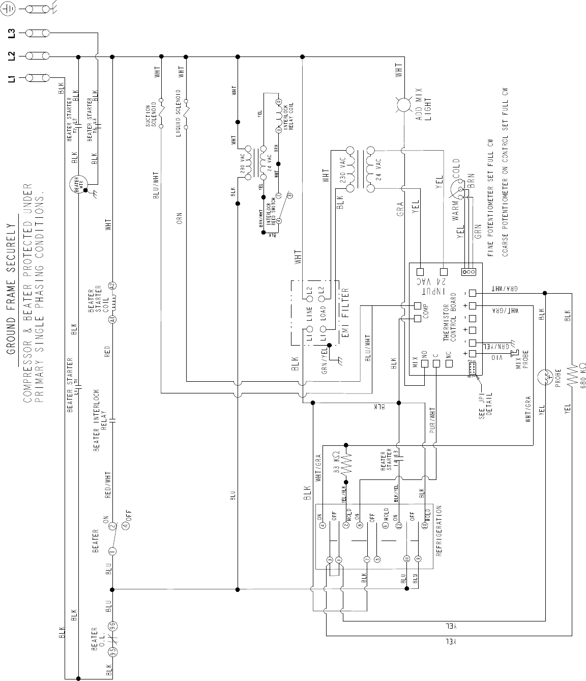
C043
063943-33B
Rev. 2/12
