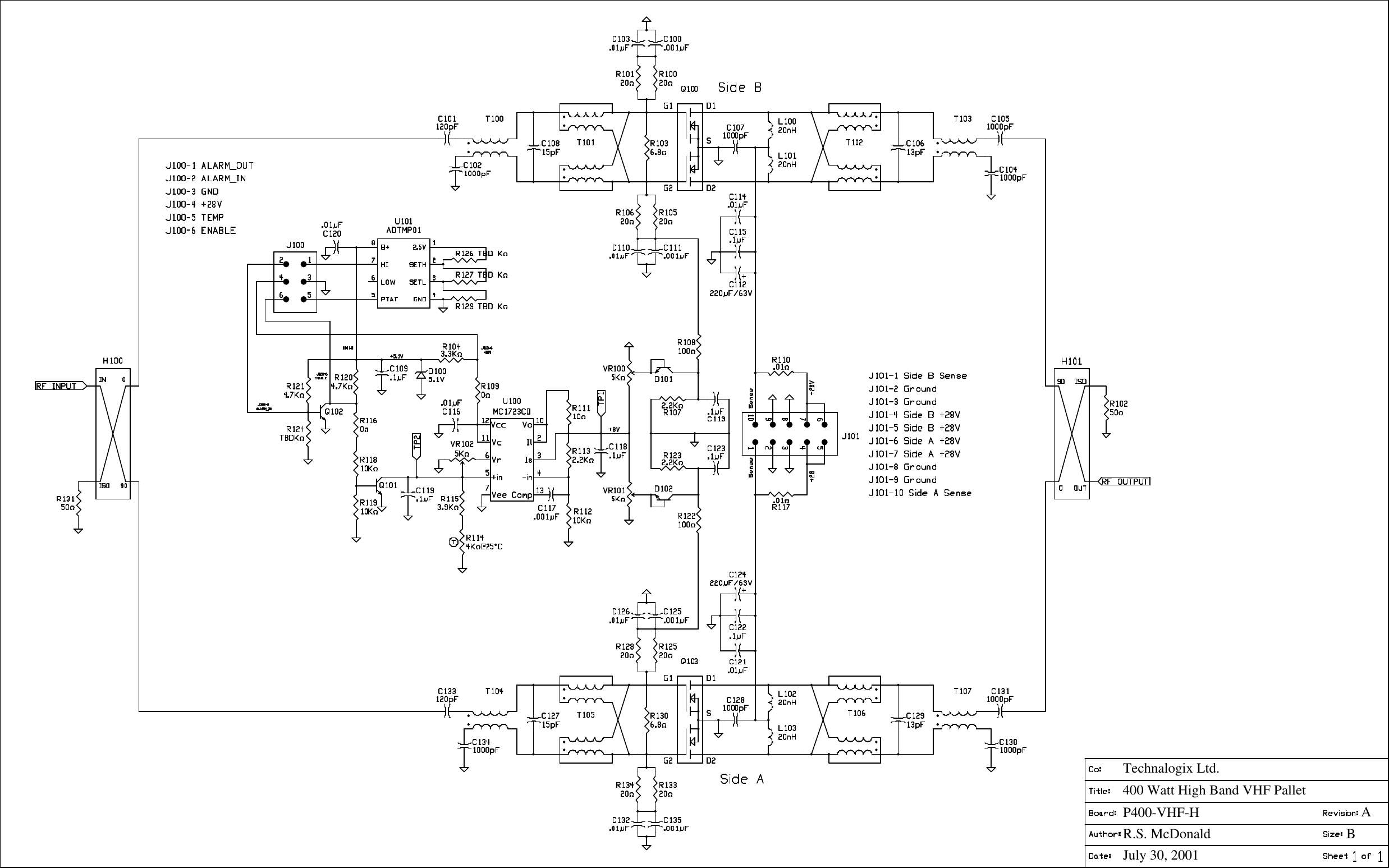
Technalogix TXVD500H 8VSB TELEVISION TRANSMITTER User Manual TAVD 500

Technalogix, Ltd. 8VSB TELEVISION TRANSMITTER TAVD 500

Contents

Users Manual

                                                                                      TAVD-500 POWER AMPLIFIER
You’ve already unpacked it, haven’t you? You’ve unpacked it and plugged it in and turned it on and fiddled with the knobs. No? Okay, good. Please take a few minutes to read the manual and familiarize yourself with your new Technalogix power amplifier.  We believe that this manual, and of course our equipment, should be everything you need to get on the air with superb broadcast quality video. We understand that a capable and confident user will get the most out of our product and we have made every attempt to educate readers of all technical levels. If there is something that is not clear, or you require further information, please do not hesitate to contact us and we’ll be glad to help out.   Technalogix Ltd. #4, 8021 Edgar Industrial Place Red Deer, Alberta, Canada T4P 3R3 Phone: 403.347.5400 Fax:   403.347.7444 URL:  www.technalogix.ca Email: technical@technalogix.ca sales@technalogix.ca    We truly appreciate that you have chosen us as your television broadcast system supplier. Happy viewing.
Table of Contents  SECTION I- SAFEGUARDS ................................................................................................................. I-1 SAFETY AND FIRST AID.................................................................................................................... I-2 OPERATING SAFEGUARDS ............................................................................................................... I-3  SECTION II -  WARRANTY ................................................................................................................ II-1  SECTION III - OVERVIEW................................................................................................................. III-1 STANDARD FEATURES ................................................................................................................... III-1 PRINCIPLE OF OPERATION ............................................................................................................. III-2 BLOCK DIAGRAM (TAVD-500)....................................................................................................... III-3 RF SIGNAL PATH ........................................................................................................................... III-4 BLOCK DIAGRAM (TAVD-500)....................................................................................................... III-3 SPECIFICATIONS ............................................................................................................................ III-5  SECTION IV - RF COMPONENTS......................................................................................................IV-1 AMPLIFIER PALLETS ......................................................................................................................IV-1 SPLITTER/COMBINER .....................................................................................................................IV-4 DIRECTIONAL COUPLER .................................................................................................................IV-4 ISOLATOR......................................................................................................................................IV-4 FILTER ..........................................................................................................................................IV-4  SECTION V - POWER SUPPLY SECTION ............................................................................................V-1  SECTION VI - MONITOR AND CONTROL SYSTEM ..............................................................................VI-1 CONTROL BOARD OVERVIEW (INSIGHT)..........................................................................................VI-1 USER INTERFACE MODULE .............................................................................................................VI-2 COUPLER CONDITIOING MODULE ....................................................................................................VI-3 RF CONDITIONING MODULE ...........................................................................................................VI-3 TEMPERATURE SENSOR MODULE...................................................................................................VI-3 TXNET MODULE .............................................................................................................................VI-3 REMOTE PORT...............................................................................................................................VI-4 FAULT SHUTDOWN.........................................................................................................................VI-5 BILL OF MATERIALS ......................................................................................................................VI-6 SCHEMATICS ...............................................................................................................................VI-12  SECTION VII - MECHANICAL SECTION ............................................................................................VII-1  SECTION VIII - INSTALLATION.......................................................................................................VIII-1 BUILDING RECOMMENDATIONS.....................................................................................................VIII-1 HEATING AND COOLING REQUIREMENTS.......................................................................................VIII-2 ELECTRICAL SERVICE RECOMMENDATIONS ..................................................................................VIII-3 ANTENNA AND TOWER RECOMMENDATIONS .................................................................................VIII-4 SHELTER SECURITY.....................................................................................................................VIII-5 UNPACKING AND INSPECTION.......................................................................................................VIII-6 LOCATION AND FUNCTION OF CONTROLS AND CONNECTORS (TAVD-500 POWER AMPLIFIER).......VIII-7 LOCATION AND FUNCTION OF CONTROLS AND CONNECTORS (COMBINER ENCLOSURE .................VIII-11
INITIAL HOOK UP……………………………………………………………………………………… VIII-13  SECTION IX - OPERATING PROCEDURE...........................................................................................IX-1  SECTION X - MAINTENANCE AND TROUBLESHOOTING.......................................................................X-1 TROUBLESHOOTING ........................................................................................................................X-2
 I-1 Technalogix Ltd  TAVD-500 Transmitter Section I - Safeguards  General Safeguards  This section is written as a general guide to keep all 5 fingers on your hand and is intended for those having previous knowledge and experience with these kinds of equipment. It is not intended to contain a complete statement of all safety precautions, which should be observed by personnel using this or other electronic equipment.     DOCUMENTATION - Read, retain and follow instructions before operating the equipment. There is a lot of useful information in the manual, and besides, we spent a lot of time writing it!     ENVIRONMENT - To reduce the risk of fire or electric shock, do not expose this equipment to rain, moisture, or rye and sodas at the company Christmas party. Refer all servicing to qualified service personnel.     SERVICING - Do not attempt to service this equipment yourself as opening or removing covers can result in a warm tingly feeling and will void the warranty.  Refer all servicing to qualified service personnel.
 I-2 Technalogix Ltd  TAVD-500 Transmitter Safety and First Aid  Personnel engaged in the installation, operation, maintenance, or servicing of electronic equipment are exposed to the hazard of high voltage.  It is imperative that all safety regulations and precautions are consistently observed.  Knowledge of first aid procedures is recommended.  The following information is presented as a reference only.  •  At all times, avoid placing any part of the body in series between ground and circuit points, whether power is on or off.  •  Dangerous voltage may be present in equipment even though power is off.  Do not open the cabinet.  Refer servicing to qualified service personnel.  •  It is the duty of all personnel to be prepared to give adequate emergency first aid treatment and thereby prevent avoidable loss of life.  •  There are three principle degrees of burns, recognizable as follows: •  a first-degree burn reddens the skin. •  a second-degree burn blisters the skin. •  a third degree burn chars the flesh and frequently places the victim in a state of shock accompanied by respiratory paralysis.  •  Respiratory paralysis can cause death by suffocation within seconds.  It is imperative that the approved methods of artificial respiration are initiated immediately and continue until the victim’s breathing is normal.  •  A muscular spasm of unconsciousness may render the victim unable to break free of the electric power.  If this is the case, turn the power off immediately.   DO NOT TOUCH THE VICTIM OR YOU MAY SHARE THE SAME PREDICAMENT.  •  If the power cannot be turned off immediately, very carefully loop a dry rope, article of clothing, length of strong cloth or a rolled-up newspaper around the victim and pull the victim free of the power source.  Carefully avoid touching the victim or clothing.  •  Once free of the power source, the victim must be placed in a reclining position and covered with a blanket or newspapers to keep warm.  At the first opportunity, enlist help in summoning a doctor.  If a doctor cannot be summoned, transport the victim to the doctor or a hospital.  Be sure the victim is kept well covered and warm while awaiting professional treatment.
 I-3 Technalogix Ltd  TAVD-500 Transmitter Operating Safeguards  It is a known fact that our broadcast transmitters and translators enjoy 50-ohm load impedances. So much so, that it is imperative you maintain 50-ohm impedances throughout your system. In return, your equipment will provide you with maximum power transfer to the antenna and decreased reflected power heading back towards the amplifier pallets, reducing the amount of magic smoke that gets let out of the power amplifier. Before anything is turned on, ensure that there is a 50-ohm path from the output of each stage to the input of the next, all the way to the antenna.  In addition to maintaining proper 50-ohm impedances throughout the signal chain, it is also important, whenever possible, to make sure the RF drive going to the input of the power amplifier is removed before turning on or turning off the DC power supply. This is because all of the RF transistors used in the individual amplifier pallets are fabricated with LDMOS (Laterally Diffused Metal Oxide Semiconductor) technology. Nice and linear yes, but they do not like to make any RF power when their supply voltages are not within a specific range. When you first turn your power amplifier on or off, the DC power supply’s output voltage may take a while to stable out to a safe operating voltage. Ten seconds wait before applying the RF drive will ensure no issues arise.  Our power amplifiers are designed to reliably generate a specific RF output power. Failing to adhere to overdriven amplifier warnings can decrease the reliability of your system, and frankly, makes our repair department busy and grumpy. If you need to transmit to a little larger coverage, you are better off increasing antenna gain, and more importantly, antenna height above average terrain. On TV and FM broadcast frequencies, insufficient antenna height puts an upper limit on your range, regardless of power levels, as the distance from your antenna to the radio horizon is limited.
 Technalogix Ltd  TAVD-500 Transmitter  II-1Section II - Warranty   Our legalese is straightforward. It is simply designed to give you peace of mind and helps you resist the temptation to have your electronics friend try to repair your Technalogix product.  Technalogix Ltd. products have been completely tested and found to meet specifications and be in proper operating condition. They are warranted to be free from defects in materials and workmanship for a period of one year from the date of shipment. If the system becomes damaged in shipment and there are obvious signs of damage to the outside of the packaging, notify your courier immediately before that courier walks out the door.  Technalogix Ltd. will not be liable for damages of whatever nature arising out of or in connection with the equipment or its use thereof. Technalogix does not assume responsibility for injury or damage resulting from the practices of untrained or unqualified personnel in the handling of this equipment.     Technalogix Ltd. warranty does not include:  •  misuse, neglect or accident. •  incorrect wiring and /or improper installation. •  unauthorized repairs, modifications or use in violation of instructions issued by Technalogix. •  incidental or consequential damages as a result of any defect. •  reshipment cost or insurance of the unit or replacement units or parts. •  acts of nature or terrorism.  Technalogix agrees, at our option, to remedy warranted defects or furnish a new part in exchange for any part of a unit which, under normal installation, use and service, becomes defective. The user will pay for transportation costs to and from the repair center. If you require technical service on the site, the cost to you will be $800.00 US per day plus air fare and meals.
 Technalogix Ltd  TAVD-500 Transmitter  II-2To claim your rights under this warranty:  •  Contact Technalogix and describe the problem in as much detail as possible. See troubleshooting section in this manual. If a solution cannot be found at this time, it may be determined that the unit will have to be returned to Technalogix for repair, once a Return Materials Authorization (RMA) number is provided.  Please look under our web site (www.technalogix.ca) for the RMA form (Service) and fill it out.  Either fax it to us or email to us.  •  Package equipment carefully for prepaid shipment to Technalogix.  Include a written description of the problem experienced, a copy of the original invoice establishing warranty status, and the RMA.  Technalogix reserves the right to make revisions in current production of the equipment and assumes no obligation to incorporate these changes in earlier models.      Shipping Address:        Technalogix Ltd.       ATTN: RMA#          #4, 8021 Edgar Industrial Place       Red Deer, Alberta, Canada       T4P 3R3       Ph: 403.347.5400             Made in Canada, returned for repairs
 Technalogix Ltd  TAVD-500 Transmitter  II-3  Terms & Conditions of Sale Sales by Technalogix Ltd (“Seller”) are made only on the terms which are contained in this Terms and Conditions of Sale Policy.  Seller hereby gives notice of its objection to any different or additional terms and conditions.  All sales are expressly conditional upon Buyers’ assent to the terms and conditions set forth below.  These terms and conditions may be modified or supplemented only by a written document sighed by the authorized representative of Seller.  These terms and conditions supersede any prior and/or contemporaneous agreements or correspondence between Buyer and Seller.  Any order received and accepted by Technalogix Ltd (Seller) shall be construed as an acceptance of Seller’s offer to sell its products to the purchaser (Buyer) in accordance with the terms and conditions of sale set forth herein.  No waiver, whether express or implied, by Seller of any of the terms or conditions hereof shall be deemed a continuing waiver or trade custom between the parties, but shall apply solely to the instance to which the waiver is directed.  Ordering Information All orders must be in writing and/or accompanied by a PO.  50% down payment is required with all orders.  No orders are considered an order until the down payment has been paid.  Order Confirmation A purchase order is not binding on Seller until Buyer has received Seller’s order confirmation or acknowledgement.   Pricing Policy Prices for products do not include taxes or any additional charges.  All prices are FOB shipping point and prices do not include freight/handling charges and insurance charges.  All prices are in U.S. currency.  All prices published or quoted by Seller may be changed at any time without notice.  Unless otherwise specified, written quotations expire thirty (30) days from the date issued and are subject to change or termination by notice during this period.  Taxes Prices for all products do not include any sales, use, excise or other taxes.  Buyer agrees to pay all applicable federal, state, and local taxes, duties and other fees on product and services ordered.  If Buyer claims an exemption form any tax, Buyer shall submit to Seller the appropriate exemption certificates.  Shipping Shipping is the responsibility of the Buyer.  This includes all freight, custom and brokerage charges and duties.
 Technalogix Ltd  TAVD-500 Transmitter  II-4     Terms of Payment Seller will provide credit terms to Buyer at its discretion.  Such terms are subject to change at all times.  If credit is provided, Seller will invoice Buyer on the date the product is ordered.  Such invoices will be due and payable net thirty (30) days from date of invoice, subject to credit approval.  If credit is not established or maintained, terms shall be net cash on or prior to the Delivery Date.  Seller reserves the right, at its sole discretion at any time to revoke any credit previously extended.  Past due accounts shall be charged two percent (2%) per month, or the highest rate permitted by Alberta law, whichever is less, and will be added to the outstanding balance.  In the event Buyer defaults on payment, Buyer shall be liable for all collection cost, including reasonable attorney’s fees and costs.  Changes and Cancellation Purchase orders that have been accepted by Seller may not be changed or cancelled, in whole or in part, without written consent of Seller.  All changes must be include in a change order reflecting the purchase order number and submitted to the Seller.  All other changes will not be accepted or acknowledged.  Changes may affect delivery dates.  Expenses incurred because of the changes shall be charged to the Buyer.  Buyer will be liable for Seller’s costs incurred, plus a reasonable profit, for the portion of the work terminated, in accordance with generally accepted accounting principle, together with cancellation charges.  Orders for standard product may be changed by Buyer, with no penalty to the Buyer, provided that Buyer provides Technalogix notification at least 30 days prior to the scheduled ship date.  Order changes received within 30 days of the scheduled ship date may be subject to an order change charge; a schedule detailing these charges will be forwarded to Buyer when Buyer’s change order is acknowledged.  In no event can any aspect of the order be changed after product shipment has occurred.  Orders for custom product may be canceled by Buyer, provided that Buyer pays Seller for completed work allocated to Buyer’s order at the time of termination of the work at the unit selling price and all costs, direct and indirect for work-in-progress as well as costs resulting from cancellation and a reasonable profit therein.  Specific cancellation charges will be dependent on the type of custom product ordered; a schedule detailing these charges will be forwarded to Buyer when Buyer’s cancellation is acknowledged.  Orders for custom product are subject to a cancellation fee of up to 100% of the order, depending on the stage of completion of the order at the date the cancellation or revision is accepted.  Custom Products Policy Custom items are not returnable; items other than “off the shelf” products are considered custom.  Custom products, by their nature, are products and materials which have been altered, modified, cut, amended and customized to your order, and are not resalable or returnable.
 Technalogix Ltd  TAVD-500 Transmitter  II-5Orders for custom product are subject to a cancellation fee of up to 100% of the order, depending on the stage of completion of the order at the date the cancellation or revision is accepted.    Returns The return of Products without a written authorization by Seller will not be accepted.  Returns are accepted only with a valid Return Material Authorization (RMA) number for items to be returned.  To receive authorization for Product return, please call customer service.  There is a standard 25% restocking cost assessed on most returns.  All returned products must be unused, and in original condition.  No refund or credit shall be given for damaged products.    We do not accept return packages without a valid RMA number and we do not accept postage-due or C.O.D. packages at any time for any reason.  Excusable Delay Seller shall not be liable for any loss or damage resulting from any delay in delivery or failure to deliver which is due to any cause beyond Seller’s control, including, without limitation, acts of nature, unavailability of supplies or sources of energy, riots, wars, fires, floods, epidemics, lockouts, strikes and slowdowns, delays in delivery by supplies, or acts or omissions of the Buyer.  The Buyer shall be liable for stage charges, including but not limited to all third party costs and expenses incurred by Seller, in holding or storing products for the Buyer or at the Buyer’s request.  Assignment Buyer shall not assign any duties nor assign any order or any interest therein without the written consent of the Seller.  Any such actual or attempted assignment shall entitle Seller to cancel the order upon written notice to Buyer.  Installation Seller assumes no obligation to install any product sold or to place any products in working order at Buyer’s premises  Validity of Separate Clauses If any provisions of this agreement shall be held invalid, illegal, or unenforceable, the validity, legality or enforceability of the remaining provisions shall not be affected or impaired thereby.
Technalogix Ltd  TAVD-500 Transmitter   III-1  Section III – Overview  Standard Features   •  Narrow output bandpass filter allows adjacent channel operation  •  Front panel Liquid Crystal Display (LCD) to monitor forward and reflected RF power, and DC voltage  •  Microcontroller-based monitoring and control ensures amplifier will never be overdriven and high VSWR will not damage amplifier  •  AC circuit breaker on back panel to eliminate replacement of fuses  •  All aluminium enclosure maintains power amplifier’s light weight  •  Simple design using commonly available parts ensures reliable operation
Technalogix Ltd  TAVD-500 Transmitter   III-2Principle of Operation  The TAVD-500 power amplifier supplies a 500-watt (rms) 8VSB television signal on any of the VHF television channels 2 through 13.  Please note that channel selection must be made at time of order, as the transmitter or translator is calibrated and tested to the channel requested and is not field tuneable. The TAVD-500 power amplifier is a modular solid-state system comprised a TAVD-500 500-watt broadcast amplifier utilizing readily available RF components wherever possible, thus enhancing the serviceability of the equipment.   Each TAVD-500 is comprised of a VHFTV-25 and a VHFTV-200 driver pallet and (4) VHFTV-400 final pallets that are combined to create 500 watts (rms) 8VSB power. The amplifier modules are stable for high reliability and long service life.  The TAVD-500 features ultra linear amplification and individual channel RF output bandpass filtering.   The following block diagram illustrates the 500-watt system.
FILTERTAVD-500 AMPLIFIERModulator or ProcessorExternal power supplyRF Out  TAVD-500 BLOCK DIAGRAMDate: May 21, 2009 Page: 1 of 1Rev ID
Technalogix Ltd  TAVD-500 Transmitter   III-4TAVD-500 Block Diagram  The RF signal enters through the RF Input connector on the power amplifier enclosure from the modulator or processor. It then passes through an RF attenuator to limit the output power level of the power amplifier and to help buffer any transients that may come into the power amplifier. After attenuation, the signal gets preamplified through the two driver pallets before the signal gets split into (4) signals for final amplification. The output of the (4) final amplifier pallets get combined and passes through an isolator. Finally, the signal passes through a dual directional coupler for monitoring purposes before heading out to the combiner/filter enclosure and then through to the antenna.
VHFTV-200 Driver    PalletVHFTV-25  Driver PalletA=-0.05dB typicalA=-0.5dB  typica lTo Wattmeter and AntennaVHFTV-400H FINAL AMPLIFIER PALLETVHFTV-400H FINAL AMPLIFIER PALLET4 WAY SPLIITER 4 WAY COMBINERRF INPUT RF OUT  Directional CTERMINATION50 OHMATTENUATIONTAVD-500 Power Amplifier Block DiagramDate: May 21, 2009 Page: 1 of 1Rev ID
Technalogix Ltd  TAVD-500 Transmitter   III-6 Specifications  Electrical specifications that are specific to the unit are included with the shipment in addition to being kept on file at Technalogix.   Physical Characteristics  Power Requirements Power Supply 220 VAC, 11 AACOperating Temperature  0 - 50°CDimensions  TAVD-500 Power Amplifier  W-19" flange (17” encl.), D-25-¼", H-101/2” (6U)Filter  W-19" flange (17” encl.), D-25-¼", H-8-¾” (5U)Power Supply  W-19" flange (17” encl.), D-25-¼", H-5-1/4” (3U)
 Technalogix Ltd  TAVD-500 Transmitter IV-1Section IV – RF Components   Amplifier Pallets  The VHFTV-25 pallet is a two stage ultra linear class-A linear pallet.  The VHFTV-25-L has a typical gain of 36dB and the VHFTV-25-H has a typical gain of 34dB.  These pallets draw no more than 3.5Adc total drain current (the exact bias and drain currents of your system are found in the spec sheet supplied with each manual). The quiescent and drain currents can be measured on the VHFTV-25 pallet by measuring the voltage drop across the current sense resistor found directly at the DC power supply lead input to the pallet. This resistance is 0.01-ohms, providing a 10mV per ampere ratio.  The VHFTV-200 pallet is a two stage ultra linear class-A linear pallet.  The VHFTV-200-L and –H pallets have a typical gain of 20dB and the VHFTV-200-H has a typical gain of 18dB.  These pallets draw no more than 4 Adc total drain current (the exact bias and drain currents of your system are found in the spec sheet supplied with each manual).   The final amplifier stage is comprised of a VHFTV-400-L or VHFTV-400-H amplifier pallet and are characterized with typical gains of 18 dB (low band) or 16dB (high band) and maximum drain currents of 17 A (low and high band) for 8VSB systems.  Each of the amplifier pallets is connectorized.  All amplifier pallets must have the transistor drain voltages reach at least 26Vdc before the RF drive is applied.
Technalogix Ltd.25 Watt High Band VHF PalletPA25-VHF-HS. KazarianNovember 12, 2001BB
Technalogix Ltd.200 Watt High Band VHF PalletP200-VHF-HR.S. McDonaldDecember 17, 2001BAA
Technalogix Ltd.400 Watt High Band VHF PalletP400-VHF-HR.S. McDonaldJuly 30, 2001BA
 Technalogix Ltd  TAVD-500 Transmitter IV-5Filter  The passive bandpass filter rejects spurious and harmonic output products and passes the VHF channel RF output. The cavity resonator uses aperture coupling and is a linear resonator design. Typical insertion loss is 0.6 dB to 1.0 dB depending on channel frequency. Average roll off is –33 dBc at a point 4.5 MHz below the peak visual carrier frequency and –30 dBc 9.0 MHz above the peak visual carrier frequency. The filter is DC grounded on both the input and output for additional lightning protection.   Directional Coupler  The Technalogix dual directional couplers provide DC voltages proportional to forward and reflected RF power monitoring. These analog voltages are converted for processing using analog-to-digital converters and provide the control system with valuable data for monitoring purposes.  Output power should be set following the operating procedure found elsewhere in this manual.  The directional coupler has a typical insertion loss of 0.5dB and its Type N connectors can handle 1,500-watts peak while the 7/16” DIN connectors can handle over 3,000-watts peak.  Isolator  The power amplifier pallets are protected in part by the isolator located in the power amplifier enclosures. It is actually made up of a circulator and 50-ohm dump resistor. The circulators’ specifications include an insertion loss of less than 0.2dB with an isolation rating better than 20dB. Any reflected power gets dumped into the flanged power resistor. Even though the flanged power resistor is rated for only 150-watts, and there could potentially be 500-watts being reflected back into the circulator, the software will recognize quickly that reflected power is present and turn the carrier off. This way, there is instantaneous protection due to the isolator setup and long term protection due to the software.
  Technalogix Ltd  TAVD-500 Transmitter V-1Section V – Power Supply   Switching AC-DC power supplies are used to power the amplifier pallets, the control circuits, and all of the fans. The power supply is set at  30.0 Vdc nominally. All fans run off this same supply, though they pass through a series dropping resistor to lower the supply voltage, as the fans are 24Vdc.   The (2) power supplies found in the power supply enclosure are Mean Well RSP-1500-27. The switching power supplies are fully protected against short circuit and output overload. Short circuit protection is a cycling type power limit. The internal AC fuse is designed to blow only on a catastrophic failure in the unit – the fuse does not blow on overload or short circuit. The thermal shutdown automatically recovers when the power supply chassis cools down.   AC (220Vac) is fed into the power supply enclosure via a filtered AC entry and then through a circuit breaker.
Stock No. Model No. Output Tol. Effi.R&N112311123211233112341123511236RSP-1500-5RSP-1500-12RSP-1500-15RSP-1500-24RSP-1500-27RSP-1500-485V, 0~240A12V, 0~125A15V, 0~100A24V, 0~63A27V, 0~56A48V, 0~32A²2%²1%²1%²1%²1%²1%150mV150mV150mV150mV150mV200mV80%87%87%90%90%91%ƤUniversal AC input / Full rangeƤPF>0.98@115VAC; >0.95@230VACƤUsing ZVS technology to reduce powerdissipationƤHigh power density 8.3W/in3ƤBuilt-in 12V / 0.1A auxiliary outputƤAlarm signal outputƤDC output voltage adjustment 70~100%by external resistorƤActive current sharing up to 6000W (3+1)ƤBuilt-in remote sense functionƤBuilt-in remote ON/OFF controlƤProtections: Short circuit / OverloadOver voltage / Over temp.ƤForced air cooling by built-in DC fanƤ3 years warrantyAC input voltage rangeDC adjustment rangeOverload protectionOver voltage protectionSetup, rise, hold up timeWithstand voltageWorking temperatureSafety standardsEMC standardsPacking90~264VAC; 127~370VDC-30~+10% rated output voltage105%~135% constant current limiting,shut off after 5 sec.115%~140% rated output voltage1500ms, 100ms, 10ms at full load and 230VACI/P-O/P:3KVAC, I/P-FG:1.5KVAC, 1 minute-20~70OC (refer to output derating curve)UL60950-1, TUV EN60950-1 approvedEN55022 class B conducted, EN61000-3-2,3,EN61000-4-2,3,4,5,6,8,11, ENV502042.6kg ; 6pcs / 16.6kg / 1.75CUFT1500W with PFC and Parallel Function1500W with PFC and Parallel Function. . . .. . . . . .. . . . . . . .. . . .. .. . . . . . . . .. . . . . .............................................278x 127x 83.5 mmCASE: 943²
 Technalogix Ltd  TAVD-500 Transmitter  VI-1Section VI – Monitor and Control System   Control System Overview (Insight)  The Insight control system is used for a variety of functions, the most important of which is ensuring that the transmitter continues to operate in a safe manner.  The control system also allows the user to monitor and control the transmitter from both the front panel and the remote access port.  Five modules comprise the Insight control system.  These modules work together to provide all the functions of the control system.  The modules are:  User Interface, Coupler Conditioning, RF Conditioning, Temperature Sensor, and the TxNET modules.  The operation of each module is outlined in the following sections.  For the TAUD-20-3 only, all three Power Amplifier chains are controlled by one User Interface Board and all three Power amplifiers are monitored on one LCD screen.  In case of an alarm, the unit number and the fault will be displayed on the front panel (i.e. PA2 High Reflected Power).  During the alarm situation only the error screen will be displayed while the other two units continue to run normally.  The alarm buzzer will sound different on PA1, PA2 and PA3.   User Interface Module  The primary function of the User Interface module is, as the name suggests, providing the user interface for the control system.  This circuit board is mounted to the front panel of the transmitter, directly behind the LCD display.  The membrane switch on the front panel is also connected to the User Interface module.  These components together provide the user with the ability to monitor the transmitter from the front panel.  The following parameters can be monitored from the front panel: • Forward (incident) power at the transmitter output. • Reflected (reverse) power at the transmitter output. • DC voltage of the transmitter power supply. • DC current for each pallet in the transmitter. • Digital attenuation for input signal. • Temperature of the heat sink of the transmitter. • The time since the transmitter was last shut down.
 Technalogix Ltd  TAVD-500 Transmitter  VI-2The hardware of the User Interface module is based around a microcontroller (U112).  This microcontroller interfaces directly with the LCD and the membrane switch to provide output and receive input from the user.  The microcontroller also communicates with the Coupler Conditioning board over a Controller Area Network (CAN) bus.  This communication is facilitated by two ICs, U113 and U114, and passes through a CAT5 cable attached to connector J106.  The communication link with the Coupler Conditioning module allows the User Interface module to receive information about the forward power, reflected power, and temperature of the transmitter, as well as relay commands from the user to the rest of the system.  If the transmitter includes more than one amplifier enclosure, a second CAN connection will be present between the User Interface module (J105) and the TxNET board to facilitate communication between enclosures.  Other elements of the User Interface module are also controlled by the microcontroller.  A buzzer (BZ101), a status LED (D113), and a relay to control the backlight of the LCD (RL101), are all controlled through a buffer (U116).  In order for the User Interface module to monitor the current draw of each pallet in the system, the DC supply wires pass through the User Interface module on their way from the power supply to the pallets.  The DC enters through connector J101 (6-position) from the power supply, and exits through J102 (10-position) to go to the pallets.  As the current passes through shunt resistors (R117/R118, R120/R121, R123/R124, R126/R127, R129/R130), the voltage drop is monitored by U101 through U105, buffered by U106 through U108, and sent to the analog to digital converter integrated into the microcontroller.  There are up to five circuits for which the current is monitored by this system.  As the DC supply passes through the User Interface module, it undergoes filtering to ensure that the supply to the pallets is as clean as possible.  Each of the five circuits passes through a network of transient voltage suppressors, capacitors, and inductors.  Each connection is also fused at the input to insure an over-current condition does not persist.  The fuses are a replaceable mini blade type fuse with a 42V voltage rating, and a current rating depending on application.   Coupler Conditioning Module  The Coupler Conditioning module serves to monitor the output of the directional coupler which provides a voltage proportional to the forward and reflected power at the output of the transmitter.  The Coupler Conditioning module also interfaces with each of the other boards in the control system, acting as the hub of communications for the system.  Lastly, the Coupler Conditioning board sends and receives signals through the remote access port, via the TxNET board.  The analog signals produced by the coupler for forward and reflected power are passed onto the Coupler Conditioning module by connectors J206 and J207, respectively.  Each signal is then filtered by LC networks. The analog signals are converted to digital by an analog-to-digital converter integrated into the microcontroller U202.
 Technalogix Ltd  TAVD-500 Transmitter  VI-3Aside from taking readings from the coupler, the microcontroller on the coupler conditioning module also interfaces with the RF Conditioning module (through J201) and the Temperature Sensor (through J202).  The microcontroller interfaces with the system CAN bus using U203 and U204.  Through the CAN bus, the Coupler Conditioning board is able to communicate with the User Interface module, and any other amplifier enclosures that are in the system.    The last task of the Coupler Conditioning board is to send and receive remote access signals to and from the TxNET board.  Two analog outputs, proportional to forward and reflected power and produced by the digital-to-analog converter U207 after it receives input from the microcontroller.  The analog outputs are then buffered by U206 before being sent through J208 and J209 to the TxNET board.  J208, along with J209, also bring the digital inputs and outputs from the TxNET board to the Coupler Conditioning module.  The digital signals are then connected to the microcontroller through the opto-isolators U209 through U213.   RF Conditioning Module  The RF Conditioning board is located at the RF input of the amplifier.  Its main function is to act as a variable attenuator, so that the control system can add attenuation to the input of the amplifier in order to limit the output power of the transmitter.  The RF signal comes in to the RF Conditioning module through J301 before it passes through a fixed attenuator (Pi-network) made up of R301, R302, and R303.  The signal then passes through the digitally-controlled variable attenuator U302 before exiting through J303.  The input control for the digital attenuator comes from the Coupler Conditioning module through J304.  The input signals are passed through the opto-isolators U302, U303, and U304 before being sent to the digital attenuator.  In total, five control signals go to the digital attenuator, allowing for attenuations of up to 31dB in 1dB steps.   Temperature Sensor Module  The Temperature Sensor module is a small board mounted to the main heatsink of the amplifier.  The main purpose of the temperature sensor module is to take temperature readings of the heatsink.  The temperature sensor IC is U701 which, after it has taken a reading, relays the digital information to the Coupler Conditioning module through J702.  Also passing through J702 is a driver disable signal coming from the Coupler Conditioning module.  The Temperature Sensor module simply takes this signal and passes it through to a pad, where a wire connects it to the driver pallet.
 Technalogix Ltd  TAVD-500 Transmitter  VI-4TxNET module  The TxNET module is simply a passive board that acts as an interface between the wiring on the inside of the amplifier enclosure and connections on the outside of the enclosure.  There is a high power version for systems that have more than one amplifier enclosure and a low power version, which does not have external enclosures aside from the modulator. The DB-25 connector for the remote port (J602) is attached to the TxNET module.  The signals travelling through this port are connected to the Coupler Conditioning module through J601 and J603.  The TxNET module also includes up to three straight through RJ45 connection pairs:  J604 to J605, J606 to J607, and J608 to J609. These connections are only used on systems with multiple enclosures, to pass control signals between enclosures; otherwise a low power TxNET is used.
 Technalogix Ltd  TAVD-500 Transmitter  VI-5Remote Port  The remote port allows external control of the transmission system via the DB25. The Power Amplifier enclosure does not include all the pins in the remote port like the Combiner/Filter enclosure. The overall functions of each pin on the remote port are indicated in the following table (see the Installation section for the specifics to each enclosure):  Pin Number  Description 1 Ground 2  Forward power sample1 3  Reflected power sample1 4 Carrier off2 5 Carrier on2 6  Increase carrier level (level must have been decreased) 2 7  Decrease carrier level (1dB increments) 2 9 Reset2 11  High temperature flag3 12  High VSWR flag3 13  Amplifier overdriven flag3 14 +5Vdc 15 +3.3Vdc 16 Ground 17 Ground Notes: 1. Analog output with voltage ranging from 0 to 5Vdc.     2. TTL level digital input, active on rising edge.     3. TTL level digital output, active high.  All other pins are not to be connected. Please see the Installation section for the specific pins that are used for each enclosure.
 Technalogix Ltd  TAVD-500 Transmitter  VI-6Fault Shutdowns  On the LCD (Liquid Crystal Display) the following messages may appear:       The Amplifier overdrive shutdown is set to 115%.  If the Amplifier is being overdriven (the RF output level is too high) the control system will automatically attenuate the RF input signal to the PA.  It will continue attenuating this signal until the RF output is below 115% total power.        If Reflected Power has been detected at the output of the transmitter, the unit will shut down for 4 seconds.  This occurs 5 times – If the fault is clear the PA enables itself.  If the fault still exists after 5 times, the PA disables the carrier for 10 minutes and cycles until the fault clears.  During the disable time (10 minutes) the unit will still alarm with a High Reflected message on the front panel.
 Technalogix Ltd  TAVD-500 Transmitter  VI-7  The control system monitors the temperature of a specific location of the heat sync.  If this temperature exceeds a threshold the control system will turn the RF output level down until this temperature level is reached.  The RF output level will automatically be brought back when it is safe to do so.
 Technalogix Ltd  TAVD-500 Transmitter  VI-8Monitor and Control System (Insight) Bills of Materials
Page 1Item Designations Qty Bin # Description Package1 U112 1 ICT 32001 IC MICROCONTROLLER 256 BYTE RAM 64QFP2C106, C107, C117, C118, C128, C129, C141, C142, C148, C149, C163 11 CAP 14902 CAPACITOR 0.01 uF 50V 10% SMD 08053C108-116, C119-127, C130-140, C143-145, C161 33 CAP 17202 CAPACITOR 0.1uF 50V 10% SMD 08054 C146, C147 2 CAP 07202 CAPACITOR 33pF 50V 5% SMD 08055 R101, R104, R107 R110, R113 5 RES 5012 RESISTOR 2.7KΩSMD 08056 C162 1 CAP 19602 CAPACITOR 1uF, 50V  SMD 08057 R132 1 RES 6492 RESISTOR 37.4KΩSMD 08058 R133 1 RES 5112 RESISTOR 3.3KΩSMD 08059R140, R141, R144 R145, R146, R147 R150, R151, R156 9 RES 5802 RESISTOR 10KΩSMD 080510R134, R135, R136, R137, R138, R139, R142, R143, R148 R149, R154, R155 12 RES 4502 RESISTOR 1KΩSMD 080511 R152 1 RES 3212 RESISTOR 100ΩSMD 080512 R119, R122, R125, R128, R131, R153 6 RES 7042 RESISTOR 100KΩSMD 080513 R158 1 RES 4002 RESISTOR 430ΩSMD 080514 R160 1 RES 4662 RESISTOR 1.4KΩSMD 080515 R161 1 RES 6312 RESISTOR 27KΩSMD 080516 R162 1 RES 5512 RESISTOR 6.2KΩSMD 080517 R157 1 RES 1575 RESISTOR 4.7ΩSMD 201018R117, R118, R120 R121, R123, R124 R126, R127, R129 R130 10 RES 0086 RESISTOR 0.006Ω 1% 1W SMD 251219 R159 1 POT 0843 POTENTIOMETER 10KΩ4mm SMD20R102, R103, R105 R106, R108, R109 R111, R112, R114 R115 10 RES 2346 RESISTOR 20Ω 1W SMD 251221 RN101 1 RES 5810 RESISTOR NETWORK 10KΩSMT22 F107 1 FUS 2901 RESETTABLE FUSE, POLYFUSE, 2A SMD23 F108 1 FUS 1651 RESETTABLE FUSE, POLYFUSE, .5A SMD24 L106, L107, L108, L109, L110 5 IND 0221 INDUCTOR 0.01uH 121025 Y101 1 CLK 0002 6.00 MHz CRYSTAL SMT26 U111 1 ICT 56001 IC SUPERVISOR 2.70V LOW SOT2327 U114 1 ICT 12000 IC TXRX 3.3V CAN 8-SOIC28 U113 1 ICT 12001 IC CAN CONTROLLER W/SPI 18-SOIC29 U115 1 ICT 48003 IC REG SIMPLE SWITCHER TO-263-530 U116 1 SEM 69000 IC DARL TRANS ARRAY 16-SOIC31 U117 1 ICT 48004 IC REG LINEAR LDO SOT22332 U118 1 ICT 16000 IC VOLTAGE COMVERTER 8-SOICBill of MaterialsModified: 08/03/06Circuit: User Interface Module (TV)Revision: 1.03
Item Designations Qty Bin # Description Package1C201, C202, C203, C208, C209, C210, C212, C214-C22317 CAP 14902 Capacitor, ceramic, 0.01uF, 50Vdc, +/-20% SMD 08052 C204, C211, C213 3 CAP 17202 Capacitor, ceramic, 0.1uF, 50Vdc, +/-20% SMD 08053 C205 1CAP 22271Capacitor, Tantalum, 10uF 16V SMD 35284 C206, C207 2CAP 07202Capacitor, ceramic, 33pF, 50Vdc, 5% SMD 08055L201, L202, L203, L204, L205, L206, L207, L2088IND 0221 Inductor, 0.01uH, Imax=0.45A, DCR=0.13 omhs SMD 12106 D201 1SEM 29006Diode Low ESD Protection 5.0V SOD 3237 D202, D203, D204 3SEM 29005Diode Low ESD Protection 3.3V SOD 3238 D205 1SEM 09005Diode, LED, Green SMD 06039 D206 1SEM 09010Diode, LED, Red SMD 060310 D207, D208, D209, D210 4SEM 09008 Diode, LED, Yellow SMD 060311 D211 1SEM 14001Diode, rectifier, 200V, 1A SMA12 D212 1SEM 24000Diode, zener, dual, 10V SOT-2313R201, R203, R205, R206, R207, R209, R2137RES 0002 Resistor, thick film, 5%, 0ohm, 1/8W SMD 080514 R210 1 RES 3292 Resistor, thick film, 5%, 120ohm, 1/8W SMD 080515 R212, R216, R218, R2194RES 4502 Resistor, thick film, 5%, 1kohm, 1/8W SMD 080516 R215, R217 2 RES 4872 Resistor, thick film, 5%, 2.15k, 1/8W SMD 080517RN201, RN203, RN205 3 RES 5810Resistor network, 10kohm, 8-resistors, 10-terminations, bussed, 5% SMD 251218 RN202, RN204 2 RES 4510 Resistor network, 1kohm, 8-resistors, 10-terminations, bussed, 5% SMD 251219 VR201, VR202 2POT 0841Potentiometer, 10kohm, 11-turn, 5mm, top SMT20 U201 1 ICT 56001 IC, supervisor, 2.7V, internal pull-up resistor, open drain, active low SOT-2321 U202 1ICT 32033IC, microcontroller, 16-bit, 16k X 8 program, 48 I/O, flash 64-QFP22 U203 1ICT 12000IC, CAN transceiver, 3.3V SOIC-823 U204 1 ICT 12001 IC, CAN controller, industrial temp, 3 transmit buffers, 2 receive buffers 18-SOIC24 U205 1SEM 69000IC, buffer, Darlington, array SOIC-1625 U206 1ICT 04003IC, op-amp, dual, single supply SOIC-826 U207 1ICT 18000IC, DAC, dual, 8-bit, serial SOIC-827 U208 1ICT 46001IC, voltage reference, 2.50V, +/- 0.2% SOT-2328 U209, U210, U211, U212, U213 5ICT 36001 IC, optoisolator, dual, transistor o/p, Vceo=30V SOIC-829 K201 1SWT 4003Relay, SPST, 4.5Vdc coil, SMT SMT30 Y201 1 CLK 0001 Crystal, 6.000MHz SMT31 S201 1SWT 0001Switch, DIP, 7-position, SPST SMD 0.1"32 J201, J202, J203, J204, J208, J209 6CON 45020 Connector, modular, female, 8-position, vertical, Shielded Through Hole33 J205 1CON 31502Connector, header, IDC, 0.1" spacing, 14-pos Through Hole34 J206, J207 2 CON 31521 Header, recept. 4pos, dual row, pass thru35 1PCB 129Printed circuit board, FR4, rev 1.10 -Bill of Materials  -  ASY129ACircuit: Coupler Conditioning (D-Attn)Revision: 1.10Modified: 12/1/08
Item Designations Qty Bin # Description Package1C201, C202, C203, C208, C209, C210, C212, C214-C22317 CAP 14902 Capacitor, ceramic, 0.01uF, 50Vdc, +/-20% SMD 08052 C204, C211, C213 3 CAP 17202 Capacitor, ceramic, 0.1uF, 50Vdc, +/-20% SMD 08053 C205 1CAP 22271Capacitor, Tantalum, 10uF 16V SMD 35284 C206, C207 2CAP 07202Capacitor, ceramic, 33pF, 50Vdc, 5% SMD 08055L201, L202, L203, L204, L205, L206, L207, L2088IND 0221 Inductor, 0.01uH, Imax=0.45A, DCR=0.13 omhs SMD 12106 D201 1SEM 29006Diode Low ESD Protection 5.0V SOD 3237 D202, D203, D204 3SEM 29005Diode Low ESD Protection 3.3V SOD 3238 D205 1SEM 09005Diode, LED, Green SMD 06039 D206 1SEM 09010Diode, LED, Red SMD 060310 D207, D208, D209, D210 4SEM 09008 Diode, LED, Yellow SMD 060311 D211 1SEM 14001Diode, rectifier, 200V, 1A SMA12 D212 1 SEM 24000 Diode, zener, dual, 10V SOT-2313 R202, R208, R209, R213, 4RES 5802 Resistor, thick film, 5%, 0ohm, 1/8W SMD 080514 R210 1 RES 3292 Resistor, thick film, 5%, 120ohm, 1/8W SMD 080515 R212, R216, R218, R2194RES 4502 Resistor, thick film, 5%, 1kohm, 1/8W SMD 080516 R215, R217 2 RES 4872 Resistor, thick film, 5%, 2.15k, 1/8W SMD 080517RN201, RN203, RN205 3 RES 5810Resistor network, 10kohm, 8-resistors, 10-terminations, bussed, 5% SMD 251218 RN202, RN204 2 RES 4510 Resistor network, 1kohm, 8-resistors, 10-terminations, bussed, 5% SMD 251219 VR201, VR202 2POT 0841Potentiometer, 10kohm, 11-turn, 5mm, top SMT20 U201 1 ICT 56001 IC, supervisor, 2.7V, internal pull-up resistor, open drain, active low SOT-2321 U202 1 ICT 32033 IC, microcontroller, 16-bit, 16k X 8 program, 48 I/O, flash 64-QFP22 U203 1ICT 12000IC, CAN transceiver, 3.3V SOIC-823 U204 1 ICT 12001 IC, CAN controller, industrial temp, 3 transmit buffers, 2 receive buffers 18-SOIC24 U205 1SEM 69000IC, buffer, Darlington, array SOIC-1625 U206 1ICT 04003IC, op-amp, dual, single supply SOIC-826 U207 1ICT 18000IC, DAC, dual, 8-bit, serial SOIC-827 U208 1ICT 46001IC, voltage reference, 2.50V, +/- 0.2% SOT-2328 U209, U210, U211, U212, U213 5ICT 36001 IC, optoisolator, dual, transistor o/p, Vceo=30V SOIC-829 K201 1SWT 4003Relay, SPST, 4.5Vdc coil, SMT SMT30 Y201 1 CLK 0001 Crystal, 6.000MHz SMT31 S201 1SWT 0001Switch, DIP, 7-position, SPST SMD 0.1"32 J201, J202, J203, J204, J208, J209 6CON 45020 Connector, modular, female, 8-position, vertical, Shielded Through Hole33 J205 1CON 31502Connector, header, IDC, 0.1" spacing, 14-pos Through Hole34 J206, J207 2 CON 31521 Header, recept. 4pos, dual row, pass thru35 1PCB 129Printed circuit board, FR4, rev 1.10 -Bill of Materials  -  ASY129BCircuit: Coupler Conditioning (V-Attn)Revision: 1.10Modified: 12/1/08
RF Conditioning (DC Filter, VHF)1.121-Dec-08Item Designations Qty Bin # Package1 C301 1CAP 15702Capacitor, ceramic, 0.022uF, 50Vdc, +/-10% SMD 08052 C302, C305 2CAP 14902Capacitor, ceramic, 0.01uF, 50Vdc, +/-10% SMD 08053 C303 1CAP 17202Capacitor, ceramic, 0.1uF, 50Vdc, +/-20% SMD 08054D302 1SEM 09005Diode, LED, green, Vf=2.1V SMD 06035D303, D304, D305, D306, D307 5SEM 09008 Diode, LED, yellow, Vf=2.0V SMD 06036L301 1IND 0832Inductor, 0.1uH, 5% (VHF only) SMD 10087R301 1RES 0002Resistor, thick film, 0-ohm, 1/8W SMD 08058R304, R309, R310, R315, R316, R319 6RES 4502 Resistor, thick film, 1%, 1k, 1/8W  SMD 08059R305, R306, R311, R312, R317 5RES 4582 Resistor, thick film, 1%, 1.2k, 1/8W  SMD 080510 R307, R308, R313, R314, R318 5RES 5802 Resistor, thick film, 1%, 10k, 1/8W  SMD 080511 U301 1ICT 50003IC, 5 Bit,Digital attenuator, LSB 1 dB w/Driver 20-SSOP12 U302, U303, U304 3ICT 36001IC, optoisolator, dual, transistor o/p, Vceo=30V SOG.050/8B13 S301 1SWT 0016Switch dip low pro, 1 pos Gold14 J303 1CON 64532Connector, high rel socket, 2mm, SMM series15 J301, J302 2CON 57017Connector, SMA, female,PCB vertical mount16 J304 1CON 45020Connector, 8-8 mod jack, shielded 7188VSANF(THT)17 C304 1TRM 0006Trimmer, variable, 9pF-90pF, 50V SMD18 PCB 1PCB 0009Printed circuit board, FR4, 0.031", 1oz -Modified:Bill Of Materials - ASY 0009BCircuit:Revision:
RF Conditioning (no DC filter)1.121-Dec-08Item Designations Qty Bin # Package1 C301 1CAP 15702Capacitor, ceramic, 0.022uF, 50Vdc, +/-10% SMD 08052 C302, C305 2CAP 14902Capacitor, ceramic, 0.01uF, 50Vdc, +/-10% SMD 08053 C303 1CAP 17202Capacitor, ceramic, 0.1uF, 50Vdc, +/-20% SMD 08054D302 1SEM 09005Diode, LED, green, Vf=2.1V SMD 06035D303, D304, D305, D306, D307 5SEM 09008 Diode, LED, yellow, Vf=2.0V SMD 06036R301 1RES 0002Resistor, thick film, 0-ohm, 1/8W SMD 08057R304, R309, R310, R315, R316, R319 6RES 4502 Resistor, thick film, 1%, 1k, 1/8W  SMD 08058R305, R306, R311, R312, R317 5RES 4582 Resistor, thick film, 1%, 1.2k, 1/8W  SMD 08059R307, R308, R313, R314, R318 5RES 5802 Resistor, thick film, 1%, 10k, 1/8W  SMD 080510 U301 1ICT 50003IC, 5 Bit,Digital attenuator, LSB 1 dB w/Driver 20-SSOP11 U302, U303, U304 3ICT 36001IC, optoisolator, dual, transistor o/p, Vceo=30V SOG.050/8B12 J301, J302 2CON 57017Connector, SMA, female, PCB vertical mount13 J304 1CON 45020Connector, 8-8 mod jack, shielded 7188VSANF(THT)14 PCB 1PCB 0009Printed circuit board, FR4, 0.031", 1oz -Modified:Bill Of Materials - ASY0009ACircuit:Revision:
RF Conditioning (DC Filter, UHF)1.121-Dec-08Item Designations Qty Bin # Package1 C301 1CAP 15702Capacitor, ceramic, 0.022uF, 50Vdc, +/-10% SMD 08052 C302, C305 2CAP 14902Capacitor, ceramic, 0.01uF, 50Vdc, +/-10% SMD 08053 C303 1CAP 17202Capacitor, ceramic, 0.1uF, 50Vdc, +/-20% SMD 08054D302 1SEM 09005Diode, LED, green, Vf=2.1V SMD 06035D303, D304, D305, D306, D307 5SEM 09008 Diode, LED, yellow, Vf=2.0V SMD 06036L301 1IND 0831Inductor, 0.01uH, 10% (UHF only) SMD 08057R301 1RES 0002Resistor, thick film, 0-ohm, 1/8W SMD 08058R304, R309, R310, R315, R316, R319 6RES 4502 Resistor, thick film, 1%, 1k, 1/8W  SMD 08059R305, R306, R311, R312, R317 5RES 4582 Resistor, thick film, 1%, 1.2k, 1/8W  SMD 080510 R307, R308, R313, R314, R318 5RES 5802 Resistor, thick film, 1%, 10k, 1/8W  SMD 080511 U301 1ICT 50003IC, 5 Bit,Digital attenuator, LSB 1 dB w/Driver 20-SSOP12 U302, U303, U304 3ICT 36001IC, optoisolator, dual, transistor o/p, Vceo=30V SOG.050/8B13 S301 1SWT 0016Switch dip low pro, 1 pos Gold14 J303 1CON 64532Connector, high rel socket, 2mm, SMM series15 J301, J302 2CON 57017Connector, SMA, female,PCB vertical mount16 J304 1CON 45020Connector, 8-8 mod jack, shielded 7188VSANF(THT)17 C304 1TRM 0006Trimmer, variable, 9pF-90pF, 50V SMD18 PCB 1PCB 0009Printed circuit board, FR4, 0.031", 1oz -Modified:Bill Of Materials - ASY 0009CCircuit:Revision:
Item Designations Qty Bin # Description Package1U701 1 ICT 52000 IC, temperature sensor, SPI 8-MSOP3C701 1 TRM 0006 TRIMMER CAPACITOR, 9-90pF THT4 C704 1 CAP 17202 CAPACITOR 0.1uF, 50V, 10% SMD 08055 C705 1 CAP 08402 CAPACITOR 100pF, 50V, 10% SMD 08056 L701 1 IND 0832 INDUCTOR, 0.1uH, 10%, 175mA, 0.80ohm SMD 08057 J701 1 CON 31525 CONNECTOR, header, 0.1", 3-position SMD8 J702 1 CON 45021 CONNECTOR, modular, jack, 8-8 R/A, shielded9 S701 1 SWT 0016 SWITCH, 1-position, SPST SMD10 1 PCB 180 PRINTED CIRCUIT BOARD, FR4, 0.062"Modified: 11/13/08Revision: 1.10Bill of Materials  -  ASY 180BCircuit: Temperature Sensor (DC Filter VHF)
Item Designations Qty Bin # Description Package1U701 1 ICT 52000 IC, temperture sensor, SPI 8-MSOP2 C702, C704 2 CAP 17202 CAPACITOR 0.1uF, 50V, 10% SMD 08053 C703 1 CAP 11502 CAPACITOR 0.001uF (1000pF), 50V, 10% SMD 08054 C705 1 CAP 08402 CAPACITOR 100pF, 50V, 5% SMD 08056 J702 1  CON 45021  CONNECTOR, modular, jack, 8-8 R/A, shielded7 1 PCB 180 PRINTED CIRCUIT BOARD, FR4, 0.062"Modified: 11/13/08Revision: 1.10Bill of Materials  -  ASY 180ACircuit: Temperature Sensor (no DC filter)
Item Designations Qty Bin # Description Package1U701 1 ICT 52000 IC, temperature sensor, SPI 8-MSOP2C701 1 TRM 0006 TRIMMER CAPACITOR, 9-90pF THT3 C704 1 CAP 17202 CAPACITOR 0.1uF, 50V, 10% SMD 08054 C705 1 CAP 08402 CAPACITOR 100pF, 50V, 10% SMD 08055 L701 1 IND 0831 INDUCTOR, 0.01uH, 10%, 540mA, 180mohm SMD 08056 J701 1 CON 31525 CONNECTOR, header, 0.1", 3-position SMD7 J702 1 CON 45021 CONNECTOR, modular, jack, 8-8 R/A, shielded8 S701 1 SWT 0016 SWITCH, 1-position, SPST SMD9 1 PCB 180 PRINTED CIRCUIT BOARD, FR4, 0.062"Modified: 11/13/08Revision: 1.10Bill of Materials  -  ASY180CCircuit: Temperature Sensor (w/ DC Filter UHF)
Item Designations Qty Bin # Description Package1 F601, F602, F603, F604 4  FUS 0801  Fuse, resettable, Ihold=0.14A, Itrip=0.34A, Vmax=60V SMD2 J601, J603 2 CON 45020 Connector, 8-8 mod jack, shielded 7188VSANF(THT)3 J602 1  CON 21000  Connector, D-sub, 25 position, female, vertical, PCB mount THT4 PCB 1  PCB 206  PCB, FR4, 0.062", red solder mask, white silk screenModified:12/1/08Circuit: TxNET LPBill of Materials: ASY 206Revision: 1.10
 Technalogix Ltd  TAVD-500 Transmitter  VI-23Insight System Schematics  The following pages contain the schematics for the Insight system.
1DC Supply ConditioningFuse Table7.5 A/side3 A15 A15 A/sideP750-FMP350-FM10 A/side15 A/side10 A/side10 A3 A2 AP400-VHF-HP400-VHF-L15 A15 AP200-VHF-LP200-VHF-HPA25-VHF-HPA25-VHF-LU200LD UHFU60LD UHFP150-UHFP50-UHF5 APA10-UHFPA5-UHF 4 AUser Interface ModuleVin     J101CTAC 58VF103see tableV3 Cond +63VC103100uFV3 InputETQ-P6F1R3LFAL103J101BTAC 58VF102see tableV2 Cond +63VC102100uFV2 InputSML-LX1206GWD104GreenETQ-P6F1R3LFAL102ETQ-P6F1R3LFAL101SML-LX1206GWD102GreenV1 Input+63VC101100uFV1 Cond TAC 58VF101see tableSMBJ48A FM D101SMBJ30A TVJ101AJ101DTAC 58VF104see tableV4 Cond +63VC104100uFV4 InputETQ-P6F1R3LFAL104SML-LX1206GWD106GreenSML-LX1206GWD108GreenSMBJ48A FM D103SMBJ30A TVSMBJ48A FM D105SMBJ30A TVSMBJ48A FM D107SMBJ30A TVJ101FGND IN  SMBJ48A FM D109SMBJ30A TVSML-LX1206GWD110GreenETQ-P6F1R3LFAL105V5 Input+63VC105100uFV5 Cond TAC 58VF105see tableJ101ETAC 58VF106tbdVgenCondSMBJ48A FM D111SMBJ30A TVR10820R10920R10520R10620R10320R102202.7k TVR1014.87k FMR11120R112202.7k TVR1044.87k FM2.7k TVR1074.87k FM2.7k TVR1104.87k FM2.7k TVR1134.87k FMR11520R11420A. Sivacoe, N. HendricksonUser Interface Module1.03 (ii) Insight Control SystemDate: November 13, 2008 Page: 1 of 6Rev ID
2User Interface ModuleCurrent MonitoringU104INA168U103INA168U102INA168C1180.01uFC1170.01uFL1070.01uHC1070.01uF C1060.01uFL1060.01uH+3.3 VdcC1090.1uFV1 Cond  V1 Out  J102AI1 Buff C1080.1uFC1130.1uFI2 Buff J102BV2 Out  V2 Cond C1100.1uF+OPA2340UAU106A+3.3 Vdc+OPA2340UAU106B C1140.1uFC1110.1uFC1120.1uFC1150.1uFC1160.1uFC1200.1uFI4 Buff V4 Cond  V4 Out  J102DC1240.1uFC1190.1uFI3 Buff J102C V3 Out  V3 Cond C1210.1uFC1250.1uF+OPA2340UAU107A+OPA2340UAU107BC1220.1uFC1230.1uFC1260.1uFC1270.1uFU101INA168R1170.012R1180.012R119100kR122100kR1210.012R1200.012R1260.012R1270.012R128100kR125100kR1240.012R1230.012A. Sivacoe, N. HendricksonUser Interface Module1.03 (ii) Insight Control SystemDate: November 13, 2008 Page: 2 of 6Rev ID
3Voltage/Current MonitoringUser Interface ModuleMembrane Switch InputsMOCD211MU109GND     J103C+3 Vdc  +3 Vdc  RESET   Sel-uPC Res-IN  Sel-IN  J103BJ103EJ103AJ103DPow-IN  Nav-IN  Pow-uPC Nav-uPC C1400.1uFC1390.1uFC1380.1uFC1370.1uFC1360.1uFI4 ADC  I4 Buff I3 Buff  I3 ADC  I5 ADC  I5 Buff I2 Buff  I2 ADC  I1 Buff  I1 ADC  V1 ADC  Vin     C1350.1uF+OPA2340UAU108BC1340.1uFC1330.1uF+OPA2340UAU108A C1320.1uFC1300.1uFJ102E V5 Out  V5 Cond I5 Buff C1310.1uF+3.3 VdcL1080.01uHC1280.01uFC1290.01uFMOCD211MU110U105INA168R15110kR15010kR1491kR148300R14710kR14610kR14010kR14110kR1421kR1431kR14410kR14510kR1391kR1381kR1371kR1361kR1351k68.1k - FMR13237.4k - TVR1333.3kR1341kR131100kR1300.012R1290.012A. Sivacoe, N. HendricksonUser Interface Module1.03 (ii) Insight Control SystemDate: November 13, 2008 Page: 3 of 6Rev ID
4MicrocontrollerUser Interface Module- DIP SWITCH 7,6,5 SET ID- DIP SWITCH 2 SETS CALIBRATION MODE- DIP SWITCH 1 ENABLES CAN BUS TERMINATIONVcc ResetGNDU111MCP130-450MSP430F133/5P8P7P6P5P4P3P2P1P9P10P11P12P13P14P15P16P48P47P46P45P44P43P42P41P40P39P38P37P36P35P34P33P17P18P19P20P21P22P23P24P25P26P27P28P29P30P31P32 P49P50P51P52P53P54P55P56P57P58P59P60P61P62P63P64U112+3.3 VdcI3 ADC  I2 ADC  I1 ADC  I4 ADC  I5 ADC  V1 ADC  Y1016.00MHZC14630pFC14730pFCAN CLK RESET   +3.3 VdcSOMI    SIMO    SCK     CAN CS  TCK     TMS     TDI     TDO     C1430.1uFC1440.1uFLCD D6  LCD D7  LCD D5  LCD D0  LCD D1  LCD D2  LCD D3  LCD D4  +5 Vdc  Pin3LCD Pin15LCDPow-uPC Nav-uPC Sel-uPC RN101 10kCANterm2CANterm1LED K   LED A   J104LCD E   LCD R/*WLCD RS  LCD Vo  LCD Vdd LCD Vss LED1    BkLtCtrlBuzzer  tbdC145L1090.01uHC1410.01uFC1420.01uF1234567P1P2P3P4P5P6P7 P8P9P10P11P12P13P147654321S101A. Sivacoe, N. HendricksonUser Interface Module1.03 (ii) Insight Control SystemDate: November 13, 2008 Page: 4 of 6Rev ID
5User Interface ModuleCAN and Programmer InterfaceJTAG HeaderJ107SN65HV232P1P2P3P4 P5P6P7P8U114MCP2510P1P2P3P4P5P6P7P8P9 P10P11P12P13P14P15P16P17P18U113TCK     TMS     TDI     TDO     J105GCANH-1  CANL-1  RESET   +3.3Vdc SOMI    SIMO    SCK     CAN CS  CAN CLK C1490.01uFJ106GCANterm1CANterm2+3.3Vdc CANL-2  CANH-2  J105HJ106H+5Vdc   +3.3Vdc RESET    RESET-2 +5V-1   +5V-2   +3.3V-2 GND-2   GND-1   +3.3V-1 J106EJ105EJ106AJ105FJ106FJ105DJ106DL1100.01uHC1480.01uFR152100R153100kA. Sivacoe, N. HendricksonUser Interface Module1.03 (ii) Insight Control SystemDate: November 13, 2008 Page: 5 of 6Rev ID
6User Interface ModulePower SuppliesLM2576U115LM2576S-5.0ULN2003P1P2P3P4P5P6P7P8 P9P10P11P12P13P14P15P16U116D11430BQ060VgenCond+5 Vdc  L111100uH+C1511000uF+3.3 Vdc+5 Vdc  C153100uF+C154100uF+C155100uFR15910k 40%Pin3LCD 10V tantalumC15210uFBkLtCtrl D116S1D-13LED1    SML-LX1206GWD113Green+C150100uFRL101G6L-1F 5VdcPin15LCDD115+5V LEDD117+3.3V LEDINCOMOUTU117LM1117MP-3.3S102Littlefuse 1812LF107Littlefuse 1812LF108Buzzer  VgenCondC15822uFC15722uFC15622uFC1621uFC1610.1uF C16022uFC15922uFL11233uHD118DIODEC1630.01uFFanOut  J108P1P2P3P4 P5P6P7P8U118LM2660MR15610kR1551ktbdR154R158430BZ101R1574.7R1626.2kR16127kR1601.4kA. Sivacoe, N. HendricksonUser Interface Module1.03 (ii) Insight Control SystemDate: November 13, 2008 Page: 6 of 6Rev ID
- DIP SWITCH 3,2,1 SET ID- DIP SWITCH 7 ENABLES CAN  TERMINATIONCoupler Conditioning Module1Microcontroller2SOMI    8GROUND  7SIMO    1SCK     6DAC2 CS +C20510uFC2040.1uFLED 6   LED 5   LED 4   LED 3   TMP SO  TMP CS  TMP SCK TMP VCC TMP GND 384J202 21C2080.01uF C2090.01uFL2030.01uHC2030.01uFC2010.01uFL2020.01uHC2020.01uFL2010.01uHLED 2   LED 1   DRVR DISCANterm2CANterm1913487RN201 10k +3.3 VdcVSWR    PSU     TEMP    OVERDRV CAR UP  CAR DOWNCAR ON  CAR OFF SOFT RES+5 Vdc  ATEN5   ATEN4   ATEN3   ATEN2   ATEN1   ATEN-Vcc57231J201 4DAC CS  TDO     TDI     TMS     TCK     CAN CS  SCK     SIMO    SOMI    +3.3 Vdc RESET   CAN CLK C20733pFC20633pFY2016.00MHZRFL-POW FWD-POW 1234567DIP SW7S201Vcc ResetGNDU201MCP130-450XinP8P7A7P6A6P5A5P4A4P3A3P2DVccP1XoutP9P10P11P1 0P12P1 1P13P14P15P16MCLKP48P47P46P45P44P43P42P41P40P39P38P37P36P35P34P33P17P18P19P20P21P2 2 P22P23P24P25P26P27P28SIMO0 P29SOMI0 P30UCLK0 P31P32 P49P50P51P52P53TDOP54TDIP55TMSP56TCKP57ResetP58A0P59A1P60A2P61AVssP62DVssP63AVccP64U202MSP430F149R206R205R208R207R204R203R202R201A. SivacoeCoupler Conditioning1.10 Insight Control SystemDate: November 13, 2008 Page: 1 of 4Rev ID
Coupler Conditioning Module2CAN and Programmer InterfaceRESET-2 J204 1C2120.01uFC2130.1uFC2100.01uFC2110.1uFJ203 4J204 4D201+5V-2   +5V-1   +5Vdc   GND-2   GND-1   J204 2J203 2J203 6J204 6D202+3.3V-1 +3.3V-2 +3.3Vdc MCP2510P1P2P3P4P5P6P7P8P9 P10P11P12P13P14P15P16P17P18U204 SN65HV232DP1GNDP2VccP3RP4 P5CANLP6CANHP7P8U203 J203 7CANH-1  CANL-1  RESET   +3.3Vdc SOMI    SIMO    SCK     CAN CS  CAN CLK C2150.01uFJ204 7CANterm1CANterm2CANL-2  CANH-2  J203 8J204 8RESET    RESET-1 J203 1L2040.01uHC2140.01uFJ205JTAGTCK     TMS     TDI     TDO     +3.3Vdc 0R209R210100A. SivacoeCoupler Conditioning1.10 Insight Control SystemDate: November 13, 2008 Page: 2 of 4Rev ID
Coupler Conditioning Module3Coupler InputInterfaceLED 3   LED 4   D206 D210+3.3 VdcLED 2   +5 Vdc  J2027DISABLE K201D211L2070.01uHC2210.01uFC2200.01uFULN2003P1P2P3P4P5P6P7P8 P9P10P11P12P13P14P15P16U205LED 1   DRVR DISLED 5   LED 6   D205 D207 D208 D209J207 3J206 3C2180.01uFL2060.01uHC2190.01uFC2170.01uFC2160.01uFL2050.01uHRFL+3.3 FWD+3.3 J206 4FWD GND FWD+5V  J206 2J206 1FWD In  RFL In  J207 1J207 2J207 4RFL GND RFL +5V +5Vdc   FWD-POW RFL-POW +3.3 VdcD203D2046 10RN2021k4 10RN2021k7 10RN2021k1 10RN2021k2 10RN2021k3 10RN2021k0R213 0R214R2111kR2121kA. SivacoeCoupler Conditioning1.10 Insight Control SystemDate: November 13, 2008 Page: 3 of 4Rev ID
RF Power Output4Remote Access Port10kVR20210kVR201MOCD211MU213MOCD211MU211MOCD211MU212MOCD211MU209FWD-OUT RFL-OUT +5 Vdc  PSU     TEMP    OVERDRV VSWR    RESET   SOFT RESCAR DOWNCAR UP  CAR ON  CAR OFF +3.3 Vdc87654321J20987654321J208C2230.01uF1 2D212B1 3D212ARFL-OUT FWD-OUT +U206ALM358+U206BLM358U208LM4040-2.5+5 Vdc  SIMO    SCK     DAC CS  L2080.01uHC2220.01uFP1P2P3P4 P5P6P7P8U207TLV5625MOCD211MU210R2172.15kR2152.15k10 9RN20310k10 8RN20310k10 6RN20310k10 7RN20310k10 6RN2041k10 7RN2041k10 9RN2041k10 8RN2041k10 4205RN10k10 3205RN10k10 6205RN10k10 7205RN10k10 2205RN10k10 8205RN10k10 9205RN10k 218R1kR2191k10 3204RN1k10 4204RN1k10 2203RN10k10 1203RN10k10 4203RN10k10 3203RN10k10 2204RN1k10 1204RN1kR2161kA. SivacoeCoupler Conditioning1.10 Insight Control SystemDate: November 13, 2008 Page: 4 of 4Rev ID
1RF ConditioningOpto-IsolationDigital AttenuationJ301J304816dB in C304L301J303S301D301J1GNDGNDGNDGNDGNDGNDGNDGNDJ2 VccC1C2VssCTL16CTL8CTL4CTL2CTL1N/CU301J302CTL 1dB CTL 2dB CTL 4dB CTL 8dB CTL 16dBC301C302C303RF OUT  RF 2    D302C305P1P2P3P4 P5P6P7P8U304P1P2P3P4 P5P6P7P8U303D307D303 D304D306D305CTL 16dBCTL 4dB CTL 8dB CTL 2dB CTL 1dB 16dB in Ext 5Vdc4dB in  8dB in  2dB in  1dB in  J3044J30412J30453J3047P1P2P3P4 P5P6P7P8U302R301R303R302R304R319R309 R310R316R315R318R317R314R313R308R307R311 R312R305 R306A. SivacoeRF Conditioning1.12 Insight Control SystemDate: November 4, 2008 Page: 1 of 1Rev ID
From CTRL To amp pallet+3.3Vdc1C705C701L701J701S7017J702Disable  J703 Disable C704C7022J702C7038J702TMP CS  TMP SCK TMP Vcc TMP SO   3J7021J7024J702TMP GND P1P2P3P4 P5P6P7P8U701LM70CIMMA. SivacoeTemperature Sensor Board1.10 Insight Control SystemDate: June 4, 2007 Page: 1 of 1Rev ID
112345678910111213141516171819202122232425J602F60487654321J603F602875432RESET   Soft RES+3.3 VdcCAR down+5 Vdc  CAR up  CAR off CAR on  ground  ODRVflagVSWRflagFWD sampTEMPflagRFL sampPSUflag  F601F6031J601TxNET1.10 LPDate: July 16, 2008 Page: 1 of 1Rev ID
IN 1    IN 2    IN 3    IN 4    IN 5    IN 6    IN 7    IN 8    1J60423456781J605 OUT 1   2345678OUT 2   OUT 3   OUT 4   OUT 5   OUT 6   OUT 7   OUT 8   OUT 8   OUT 7   OUT 6   OUT 5   OUT 4   OUT 3   OUT 2   8765432OUT 1   1J60787654321J606IN 8    IN 7    IN 6    IN 5    IN 4    IN 3    IN 2    IN 1    OUT 8   OUT 7   OUT 6   OUT 5   OUT 4   OUT 3   OUT 2   8765432OUT 1   1J60987654321J608IN 8    IN 7    IN 6    IN 5    IN 4    IN 3    IN 2    IN 1    12345678910111213141516171819202122232425J602F60487654321J603F602875432RESET   Soft RES+3.3 VdcCAR down+5 Vdc  CAR up  CAR off CAR on  ground  ODRVflagVSWRflagFWD sampTEMPflagRFL sampPSUflag  F601F6031J601TxNET1.10 HPDate: July 16, 2008 Page: 1 of 1Rev ID
 Technalogix Ltd  TAVD-500 Transmitter   VII-1Section VII – Mechanical Section   The heat sinks allow the amplifiers to operate at a cooler temperature and prevent overheating, which helps the longevity of the entire system. Each heat sink has hollow fins, which help dissipate the heat from the amplifiers faster than a conventional serrated or corrugated fin.    In addition to the cooling effects of the heat sinks, within the 500-watt power amplifier enclosure, there are six fans that each provide 170 cubic feet per minute (CFM) of air flow (into zero static pressure). There are three fans mounted at the front of the heat sink and three mounted at the back end of the heat sink. The fans are mounted side-by-side to produce the best cooling for the system and are operating in a push-pull configuration to assist with heat dissipation.  The fans are a 24Vdc variety, so there are series dropping resistors to drop the higher power supply voltage down to a safe level.
 Technalogix Ltd.   TAVD-500 Transmitter                        VIII-1Section VIII - Installation   This section contains installation recommendations, unpacking, inspection, and installation instructions for the power amplifier. We are sure that you are chomping at the bit to install your new system, so we recommend that you read the following sections very carefully.   Building Recommendations  The quality of the building is of great importance if you are to expect long life and continued performance from the power amplifier. The building must be clean, dry, temperature controlled and secure. Don’t forget to allow space in the building for any additional racks to house test equipment, a workbench area, line regulating transformers, ladders, equipment and parts storage, first aid kit, emergency generator if used, as well as heating and cooling devices that may be unique to your installation. A sloping roof will tend to develop leaks less rapidly. The building should be well roofed with good material. The cooling load will be lowered with reflective or light colored roofing material.
 Technalogix Ltd.   TAVD-500 Transmitter                        VIII-2Heating and Cooling Requirements  The environment’s temperature will contribute greatly to the length of the power amplifier’s life. Technalogix recommends that the building’s filtered air intake must have capacity for all air-flow in the building plus an additional 20%. Keep the intake below the roofline to avoid intake of solar heated air. Please ensure that the intake and exhaust areas are on the same side of the building to avoid pressure differentials during windy conditions. Also, do not position intake near exhaust’s preheated air. If air conditioning is required to cool the shelter, discuss the situation with a qualified HVAC technician. Under average conditions, 12,000 BTUs will cool approximately 500 square feet to a comfortable level. The TAVD-5000 contains (3) DC ball bearing fans in each PA (push-pull configuration) and (2) fans in each of the combiner/filter and power supply enclosure.
 Technalogix Ltd.   TAVD-500 Transmitter                        VIII-3Electrical Service Recommendations  Technalogix recommends that a qualified, licensed local electrician be consulted for the required electrical service. We suggest local electricians because:  • The personnel knows the local codes • The personnel can be on site readily • You are apt to get better overall support if you give what business you can to local suppliers  Technalogix recommends that proper AC line conditioning and surge suppression be provided on the primary AC input to the power amplifier. All electrical service should be installed with your national electrical code in your area, any applicable provincial or state codes, and good engineering practice. Special consideration should be given to lightning protection of all systems in view of the vulnerability of most transmitter or translator sites to lightning. Lightning arrestors are recommended in the service entrance. Straight and short grounds are recommended. The electrical serviced must be well grounded. Do not connect the unit to an open delta primary power supply, as voltage fluctuations could harm the unit. Branch your circuits. Do not allow your lights, your workbench plugs, and your transmitting or translating equipment to operate on one circuit breaker. Each transmitter or translator should have its own circuit breaker, so a failure in one does not shut off the whole installation.
 Technalogix Ltd.   TAVD-500 Transmitter                        VIII-4Antenna and Tower Recommendations  Your preliminary engineering workgroup should establish your antenna and tower requirements, both for receiving and transmitting antennas. Construction of sturdy, high quality antenna/tower systems will pay off in terms of coverage of your service area, the overall quality and saleability of your radiated signal, and reduced maintenance expenses. Technalogix provides complete turnkey antenna systems if needed. If your site is serving as a translator, your receiving antenna should be in line of sight to the originating station all year round. The foliage will change with season. Transmitting antennas can enhance or seriously impair the transmitter/translator output.  The selection, routing, and length of coaxial cable are extremely important in the installation. If there is a 3 dB line loss in the cable between your unit’s output and the transmitting antenna, a 1,000-watt unit will only deliver 500 watts to the antenna. Buy the best cable you can obtain, route it via the shortest way to the antenna, and keep it straight. Do not form it into sharp bends on its way. Do not use any more cable fittings for the installation than absolutely necessary. All cautions here apply equally to all coaxial cables in the system - input and output.   Pay attention to radial ice accumulation when designing the transmission system. It is not uncommon for at least an inch of ice to build up on the tower and antenna. This in turn significantly increases the weight, cross section, and wind loading of the system.  Attaching the transmission line to the tower is crucial to maintain a safe and reliable operation. Nylon wire ties and electrical tape will breakdown in the sunlight and ultimately fail, creating a potentially dangerous situation. It is important to use proper clamps and hoisting grips and also ensure that the transmission line is grounded to the tower in several locations. When high currents flow through the tower in the event of lightening strikes, some of that current will through the outer conductors of the transmission lines. Due to the resistance difference between the steel tower and copper transmission line, a significant voltage can be developed, often resulting in arcing between the outer jacket and outer conductor, thus pitting the conductor.  Preventative maintenance is crucial in ensuring that safety is maintained. Specifically, check that transmission line grounds are tight and are not missing any hardware. Frequently inspect support clamps or spring hangers. Consider investing in an ice break, if you haven’t already done so, as shards of falling ice can damage the transmission line – and if it is going to happen, it will happen at an important time. Check the tower light photocells and conduit.  The better-known tower manufacturers offer complete technical and safety documentation with their towers. Be sure that you have this information as it regards wind loading, guying, etc. The best-designed antenna system will function poorly if shortcuts and compromises are used during installation. Follow the manufacturer’s instructions exactly, along with any engineering data prepared for the site. Be absolutely safe and certain about this aspect as human lives may be at stake.
 Technalogix Ltd.   TAVD-500 Transmitter                        VIII-5Shelter Security  The FCC requires that the transmitter or translator be secure from entry or control by unauthorized persons, and that any hazardous voltages or other dangers (including most tower bases) be protected by locks or fences as necessary to protect personnel and prevent unauthorized tampering or operation. Security of the building further implies that it be secure from wildlife. Use sturdy construction materials, including sheet metal if necessary. Holes around conduit, cable, and other similar entry points should be stuffed with steel wool and caulked to prevent entry of wildlife. Other features of security for your shelter may include its location with respect to the prevailing wind conditions. A location leeward of some natural topographical feature will prevent wind damage and snowdrifts. Check the soil runoff conditions that may slow or hasten wind or water erosion and other concerns that may be unique to your location.
 Technalogix Ltd.   TAVD-500 Transmitter                        VIII-6Unpacking and Inspection  Check the outside of the container. Carefully open the container and remove the power amplifier. Retain all packing material that can be reassembled in the event that the equipment must be returned to the factory.   Exercise care in handling equipment during inspection to prevent damage due to rough or careless handling.   Visually inspect the enclosure of the power amplifier for damage that may have occurred during shipment. Check for evidence of water damage, bent or warped chassis, loose screws or nuts, or extraneous packing material in connectors or fan failures. Inspect all connectors for bent connector pins. If the equipment is damaged, a claim should be filed with the carrier once the extent of the damage is assessed. Technalogix cannot stress too strongly the importance of immediate careful inspection of the equipment and subsequent immediate filing of the necessary claims against the carrier if necessary. If possible, inspect the equipment in the presence of the delivery person. If the equipment is damaged, the carrier is your first area of recourse. If the equipment is damaged and must be returned to the factory, phone for a return authorization. Claims for loss or damage may not be withheld from any payment to Technalogix, nor may any payment due be withheld pending the outcome thereof. Technalogix cannot guarantee the carrier’s performance.
 Technalogix Ltd.   TAVD-500 Transmitter                        VIII-7 Location and Function of Controls and Connectors (TAVD-500 Power Amplifier)  The following illustration depicts the location of the connectors when installing the 500-watt power amplifier.
 Technalogix Ltd.   TAVD-500 Transmitter                        VIII-8POWER -   Tactile button to turn carriers on and off.   NAVIGATE -     Tactile button to move between menu items, or to refresh the screen after it has timed out.  SELECT-   Tactile button to select menu item, or to refresh the screen after it has timed out.  RESET -    Tactile button to reset microcontroller in control board. Also clears existing faults. The amplifier will come back on with the soft start feature.  RF IN –     RF input from modulator or processor. BNC connector, 50 ohm.  RF OUT –    500-watt (rms) RF output. Connects to combiner/filter enclosure. N connector, 50 ohm.  REMOTE PORT -  Port to monitor and control the amplifier externally.  See “ Monitor and Control” section for pin-out. Power amplifier has fault alarms only and filter/combiner has fault alarms and controls.
 Technalogix Ltd.   TAVD-500 Transmitter                        VIII-9Location and Function of Controls and Connectors (Filter Enclosure) The following illustration depicts the location of the connectors when installing the filter enclosure.
 Technalogix Ltd.   TAVD-500 Transmitter                        VIII-10  RF IN -     RF inputs (500-watts each) from the power amplifier.  N female connector, 50 ohm.  RF OUT –    500-watt (rms) RF output. Connects to inline wattmeter (not supplied) and antenna. 7/16”DIN female connector, 50 ohm.
 Technalogix Ltd.   TAVD-500 Transmitter                        VIII-11Initial Hook Up  1.  Ensure that the antenna has been swept and has a return loss of greater than 20dB (VSWR = 1.2:1). This should be done before connecting the antenna cable to the transmitter output.  2.  Check that your video source is present.  3.  Place the transmitter/translator in its permanent location near a receptacle supplying required AC voltage.   DO NOT APPLY AC POWER AND TURN ON POWER TO THE TRANSMITTER / TRANSLATOR AT THIS TIME SINCE THE RF OUTPUT MUST BE PROPERLY LOADED BEFORE OPERATION.   4.  Place an appropriate AC power line protector, conditioner, and/or surge suppressor across the AC supply line.  5.  Hook up the modulator or processor as shown in their respective manuals for a transmitter or translator. Do not connect the modulated signal from the RF OUT on the modulator or processor to RF IN on the power amplifiers at this time. Because of the characteristics of transistor devices, the RF drive should not be connected to the power amplifier until after the power supply and bias voltages are present and stable.  6.  Ensure that modulator or processor RF output level is turned down as far as possible.  7.  Hook up the PA out to the Filter in.  8.  Connect the RF Output on the filter enclosure to the wattmeter directly (no cable in between) and then the output of the inline wattmeter to the transmitting antenna cable.  9.  Plug power supply into AC mains (220 Vac, single phase).  10. Leave the AC rocker switch to “off” position.
 Technalogix Ltd  TAVD-500 Transmitter   IX-1 Section IX - Operating Procedure   Assuming the previous installation instructions have been completed and cautions noted, and the TAVD-500 power amplifier is ready to receive a properly modulated video and audio signal, proceed with the following steps to place the system in operation. The TAVD-500 power amplifier has been factory aligned for channel frequency (per system specification), signal levels and optimum performance.   IT IS HIGHLY RECOMMENDED THAT YOU RUN YOUR SYSTEM INTO A DUMMY LOAD BEFORE INSTALLING TO MAKE SURE THERE ARE NO DAMAGES CAUSED IN SHIPPING AND THE UNIT IS RUNNING PROPERLY   1.  Do not apply RF drive signal to the power amplifier at this time.  2.  Verify that all control and RF cables are tight and properly seated in or on the mating connector.  3.  Plug the modulator or processor into AC mains.  4.  With the PA output loaded, plug the 3U power supply enclosure into 220V AC mains.  5.  Switch AC rocker switch to “ON” position.  6.  Verify that the power amplifier fans are all on.  7.  Ensure that the modulator/processor is turned on and set up according to its instructions. Depress the POWER tactile button to turn the unit on.  8.  The internal soft start circuitry will turn the bias voltages off until the power supply to the amplifier pallets is fully stable. The message on the LCD indicates when the soft start is running. Once complete, the Forward and Reflected Power and Power Supply readings will appear on the LCD in the filter and power amplifier enclosures.  9.  After the soft start is complete, apply the RF drive signal (which still should be turned down) between the modulator or processor and the power amplifier RF In. This ensures that the RF drive signal is applied only after the power supply is stable and the bias voltages are applied to the amplifier.
 Technalogix Ltd  TAVD-500 Transmitter   IX-2 10. The TAVD-500 LCDs show the user the present status of the amplifiers. Adjust RF output power to desired level (see Important RF Power Notice in previous section). Verify that the FWD Power reads 400 to 500 Watts on the PA enclosure. The output power level can be adjusted using the modulator or processor’s RF output level adjust. Keep in mind that the system will shut down should the forward RF output power level be exceeded.  11. Ideally, the RFL Power should read zero. However, should a high VSWR be detected, the system will automatically shut down and cycle as previously described.   12. Verify that the power supply reads approximately 30 Volts DC (see supplied final inspection sheet for factory settings of power supply levels) on the LCD of the power amplifier.   13. Look at the transmitted output using a suitable monitor. The picture and sound quality should be clean and sharp. If the output picture and sound quality is unsatisfactory, check the input signals, connections to the antenna system, antenna and transmission line VSWR, and the physical condition of the antenna.  If reception problems are encountered, and the quality of transmission is satisfactory, the difficulty is often with the receiving antenna or with obstructions in the path between the transmitter/translator and receiver.
    Technalogix Ltd  TAVD-500 Transmitter  X-1 Section X – Maintenance and Troubleshooting  Periodic Maintenance  If your unit employs a filter on the air inlet for the fans, the filter should be cleaned every 30 days. If the equipment is operated in a severe dust environment, the filters on the inlet fan may need to be cleaned more regularly. Turn the system off and unplug all of the AC inlet cords. The filter can be lifted off the fan and cleaned using an air compressor at low pressure. While the filter is out, clean the fan blades themselves with a small brush. The fans themselves do not need lubrication.  The interior of the cabinets should be cleaned and inspected annually. Turn the system off and unplug all of the AC inlet cords. Remove the top lid by unscrewing the 6-32 machine screws.   Use extreme caution when working near the AC input terminal. The power amplifier and power supply store hazardous capacitances and voltages.   Using either compressed air or a brush with soft bristles, loosen accumulated dust and dirt and then vacuum the interior of the cabinet. Complete a visual inspection of the interior, making sure there are no loose connections or discolorations on any components from heat. Nothing inside the power amplifier enclosure exceeds a temperature that is not comfortable to the touch under normal operating conditions, so any signs of discoloration indicate potential damage.  All modular components inside the enclosure are attached to aluminium mounting plates for easy removal and replacement. Ensure that plates are secured and the mounting hardware is tight.
    Technalogix Ltd  TAVD-500 Transmitter  X-2 Troubleshooting  The first and most important aspect of troubleshooting anything is to be systematic.  Note where you have looked and what you found.  Look first for the obvious.  •  Make a physical inspection of the entire facility.  Are all necessary connections properly made?  Do you see any signs of obvious damage within the equipment?  •  Is the AC power ‘ON’ to the site and the equipment?  (Check fuses and circuit breakers if necessary.)  •  Are all the switches in the correct operating position?  •  Is the input signal present?  •  Check LCD readings for presence of forward and reflected power and 31 V DC supply levels.   The above is an aid in determining the fault if some aspect of the system is not operating. The following table deals with quality of operation:   Symptom  Possible Fault Correction Horizontal bars in picture (may roll either way depending on phase) AC grounding / AC interference  Install EMI/RFI filter in AC line   Ensure modulator/processor and power amplifier share a common ground Diagonal lines in picture  Interference  Install EMI/RFI filter in AC line   Determine source and frequency of interfering signal (spectrum analyzer may be required)
    Technalogix Ltd  TAVD-500 Transmitter  X-3   Symptom  Possible Fault Correction High reflected power  Incorrect load  Ensure amplifier connected to transmission line   Ensure correct antenna impedance (50 ohms)     Check antenna tuning and VSWR. Verify correct cable for transmission line length     Check all cables for visible damage (kinks, nicks or cuts)     Check all connectors for poor connections, water or corrosion    Check alignment of antenna     Check for physical damage of antenna, including ice build-up
Thank youfor choosingTechnalogix Ltd.

Navigation menu