Technicolor Connected Home USA LORMOD01 XB6 Lora User Manual
Technicolor Connected Home USA LLC XB6 Lora
UserManual.wiki
>
Technicolor Connected Home USA
>
LORMOD01 User Manual
User Manual
Navigation menu
Upload a User Manual
Namespaces
Wiki Guide
HTML
PDF
Info
Views
User Manual
Discussion / Help
Navigation
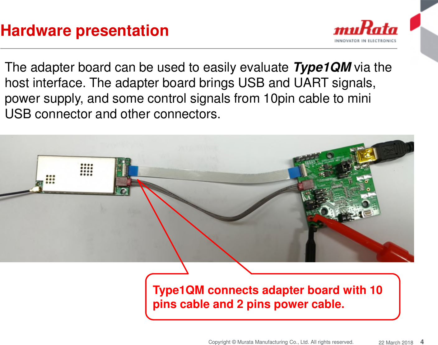
![3Copyright © Murata Manufacturing Co., Ltd. All rights reserved. 22 March 2018IntroductionThis user guide introduces Murata LoRa Pico GatewayTransceiver Module called Type1QM and how to set up theadapter board. The host interface which the module supportsincludes USB and UART.Type1QM is a multi-channel high performance transceiver designed tosimultaneously receive several LoRa packets using random spreadingfactors. This design is for USA/Australia 915 MHz ISM band [902 MHz- 928 MHz]](https://usermanual.wiki/Technicolor-Connected-Home-USA/LORMOD01/User-Guide-3796280-Page-4.png)