Technicolor Connected Home USA LORMOD01 XB6 Lora User Manual
Technicolor Connected Home USA LLC XB6 Lora
User Manual
0murata.com Copyright © Murata Manufacturing Co., Ltd. All rights reserved. 22 March 2018
Copyright © Murata Manufacturing Co., Ltd. All rights reserved. 22 March 2018
LoRa Pico Gateway
Transceiver Module (Type1QM)
User manual v1.2

1
Copyright © Murata Manufacturing Co., Ltd. All rights reserved. 22 March 2018
Table of Contents
•Module Overview
•Module Interface Overview
•Adaptor Board Overview
•Methods to Update FW in Module
–From Linux Host (e.g. Raspberry Pi)
–Using ST-Link Cable & Tool
–Using ST Dfuse Tool from Windows PC
•Appendix: Adaptor Board Schematics

2
Copyright © Murata Manufacturing Co., Ltd. All rights reserved. 22 March 2018
Table of Contents
•Module Overview
•Module Interface Overview
•Adaptor Board Overview
•Methods to Update FW in Module
–From Linux Host (e.g. Raspberry Pi)
–Using ST-Link Cable & Tool
–Using ST Dfuse Tool from Windows PC
•Appendix: Adaptor Board Schematics
3
Copyright © Murata Manufacturing Co., Ltd. All rights reserved. 22 March 2018
Introduction
This user guide introduces Murata LoRa Pico Gateway
Transceiver Module called Type1QM and how to set up the
adapter board. The host interface which the module supports
includes USB and UART.
Type1QM is a multi-channel high performance transceiver designed to
simultaneously receive several LoRa packets using random spreading
factors. This design is for USA/Australia 915 MHz ISM band [902 MHz
- 928 MHz]
4
Copyright © Murata Manufacturing Co., Ltd. All rights reserved. 22 March 2018
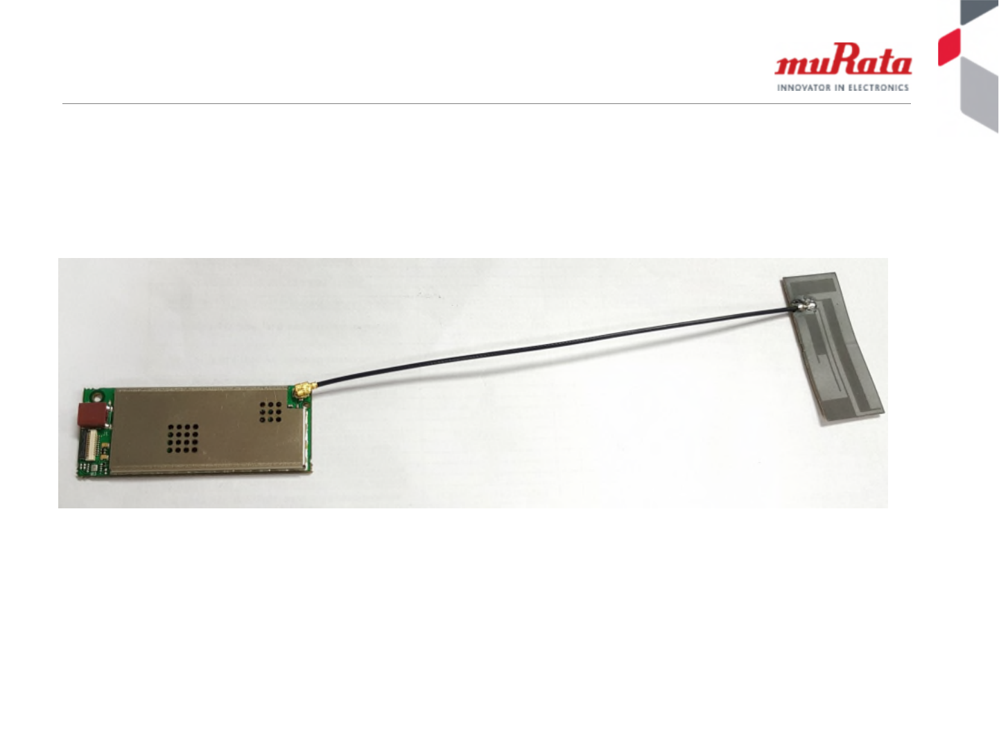
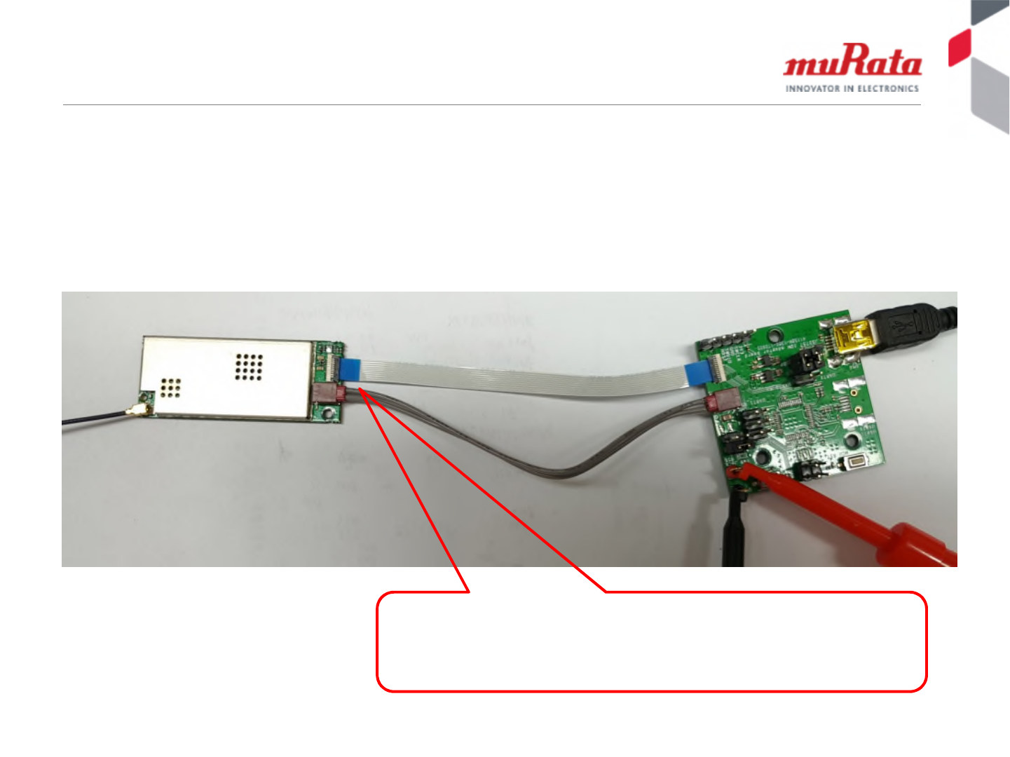
Hardware presentation
The adapter board can be used to easily evaluate Type1QM via the
host interface. The adapter board brings USB and UART signals,
power supply, and some control signals from 10pin cable to mini
USB connector and other connectors.
Type1QM connects adapter board with 10
pins cable and 2 pins power cable.

5
Copyright © Murata Manufacturing Co., Ltd. All rights reserved. 22 March 2018
Table of Contents
•Module Overview
•Module Interface Overview
•Adaptor Board Overview
•Methods to Update FW in Module
–From Linux Host (e.g. Raspberry Pi)
–Using ST-Link Cable & Tool
–Using ST Dfuse Tool from Windows PC
•Appendix: Adaptor Board Schematics
6
Copyright © Murata Manufacturing Co., Ltd. All rights reserved. 22 March 2018
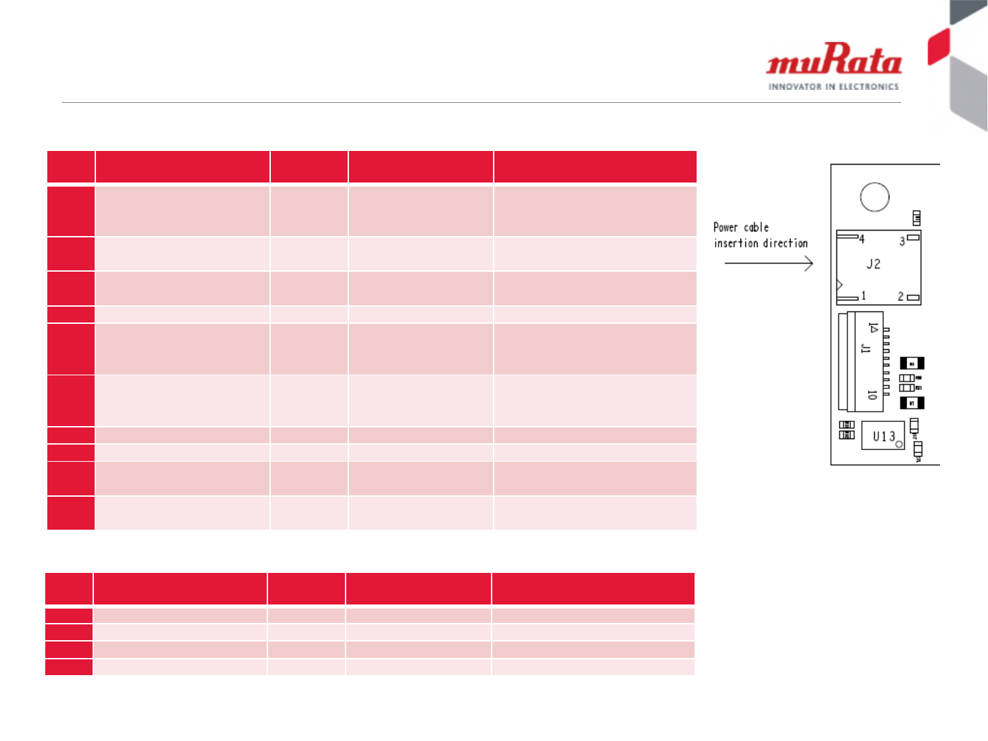
Module Pin Assignment
Pin
No. Terminal Name Type Connection to
IC terminal Description
1PWR_EN I BD9141MUV_EN Power enable/disable
1:Enable
0:Disable
2USART1_TX I/O STM32F401_PA9 GPIO Mode:PA9
USART1_TX
3USART1_RX I/O STM32F401_PA10 GPIO Mode:PA10
USART1_RX
4GND Ground - Ground
5USB_DM/USART1_CTS I/O STM32F401_PA11 GPIO Mode:PA11
USB_DM
USART_CTS
6USB_DP/USART1_RTS I/O STM32F401_PA12 GPIO Mode:PA12
USB_DP
USART_RTS
7GND Ground - Ground
8MCU_RST I STM32F401_NRST NRST
9SWDIO I/O STM32F401_PA13 GPIO Mode:PA13
SWDIO
10 SWCLK I/O STM32F401_PA14 GPIO Mode:PA14
SWCLK
Pin
No. Terminal Name Type Connection to
IC terminal Description
1GND Ground - Ground input
2GND Ground - Ground input
3VCC Power - 5V~12V power input
4NC - - NC
J1 connector
J2 connector

7
Copyright © Murata Manufacturing Co., Ltd. All rights reserved. 22 March 2018
Table of Contents
•Module Overview
•Module Interface Overview
•Adaptor Board Overview
•Methods to Update FW in Module
–From Linux Host (e.g. Raspberry Pi)
–Using ST-Link Cable & Tool
–Using ST Dfuse Tool from Windows PC
•Appendix: Adaptor Board Schematics
8
Copyright © Murata Manufacturing Co., Ltd. All rights reserved. 22 March 2018
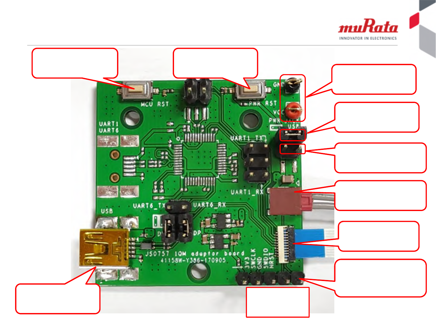
Descriptions of Adapter Board
for USB interface
If the external power
supply is applied, this
jump should be short
External power supply
5V~12V
If power supply comes from
USB 5V input, this jump
should be short
Mini USB connector
SWD connector. If you
would like to program the
new firmware, connect the
related signals to ST linker
NRST
SWDIO
GND
SWCLK
FPC connector and
cable, connecting to
Type1QM
Power connector and cable,
connecting to Type1QM
Button connected to
Pwr_EN pin, push down
to power off the module
Button connected to
STM32 MCU reset pin,
push down to reset MCU
9
Copyright © Murata Manufacturing Co., Ltd. All rights reserved. 22 March 2018
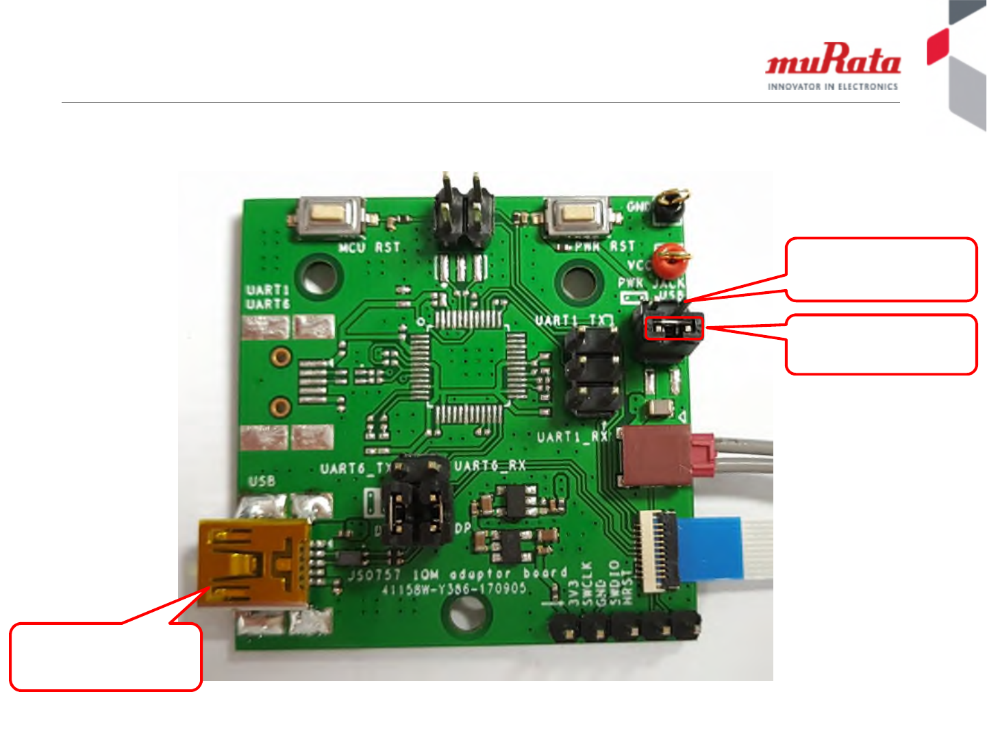
In Case of Using USB Power Supply
Short this jumper
Power supply from
USB connector
Remove this jumper
10
Copyright © Murata Manufacturing Co., Ltd. All rights reserved. 22 March 2018
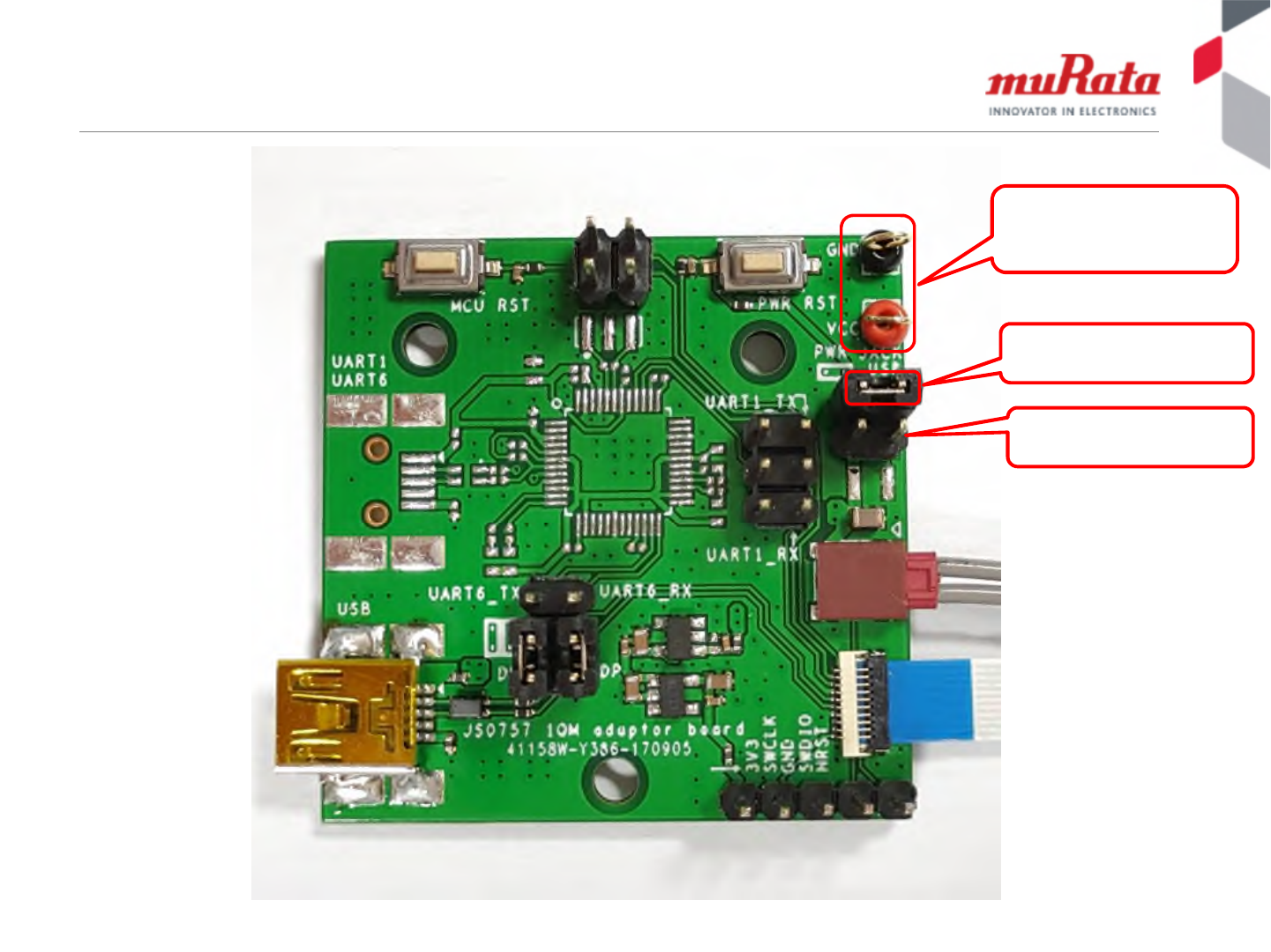
In Case of Using External Power Supply
Short this jumper
External power supply
5V~12V
Remove this jumper

11
Copyright © Murata Manufacturing Co., Ltd. All rights reserved. 22 March 2018
Table of Contents
•Module Overview
•Module Interface Overview
•Adaptor Board Overview
•Methods to Update FW in Module
–From Linux Host (e.g. Raspberry Pi)
–Using ST-Link Cable & Tool
–Using ST Dfuse Tool from Windows PC
•Appendix: Adaptor Board Schematics

12
Copyright © Murata Manufacturing Co., Ltd. All rights reserved. 22 March 2018
Firmware in Type1QM
•Test firmware which can be verify electrical performance
is preprogrammed in Type1QM.
•The following slides provide how to update the firmware
in Type1QM.
NOTE:
Only Test firmware is programmed in our production
line. Customers must update the FW which is released
by Semtech formally.

13
Copyright © Murata Manufacturing Co., Ltd. All rights reserved. 22 March 2018
Table of Contents
•Module Overview
•Module Interface Overview
•Adaptor Board Overview
•Methods to Update FW in Module
–From Linux Host (e.g. Raspberry Pi)
–Using ST-Link Cable & Tool
–Using ST Dfuse Tool from Windows PC
•Appendix: Adaptor Board Schematics

14
Copyright © Murata Manufacturing Co., Ltd. All rights reserved. 22 March 2018
Get Semtech software package
Get the lastest Semtech software package from LoRa
Github
• mkdir lora-net
• cd lora-net
• sudo apt-get update
• sudo apt-get install git
• git clone http://github.con/Lora-
net/picoGW_packet_forwarder.git
• git clone http://github.con/Lora-net/picoGW_mcu.git
• git clone http://github.con/Lora-net/picoGW_hal.git

15
Copyright © Murata Manufacturing Co., Ltd. All rights reserved. 22 March 2018
Install Dfu-util Tool
• cd ~/lora-net/
• sudo apt-get install autoconf
• git clone https://git.code.sf.net/p/dfu-util/dfu-util
• cd dfu-util
• ./autogen.sh
• sudo apt-get install linusb-1.0-0-dev
• ./configure
• make
• sudo make install
16
Copyright © Murata Manufacturing Co., Ltd. All rights reserved. 22 March 2018
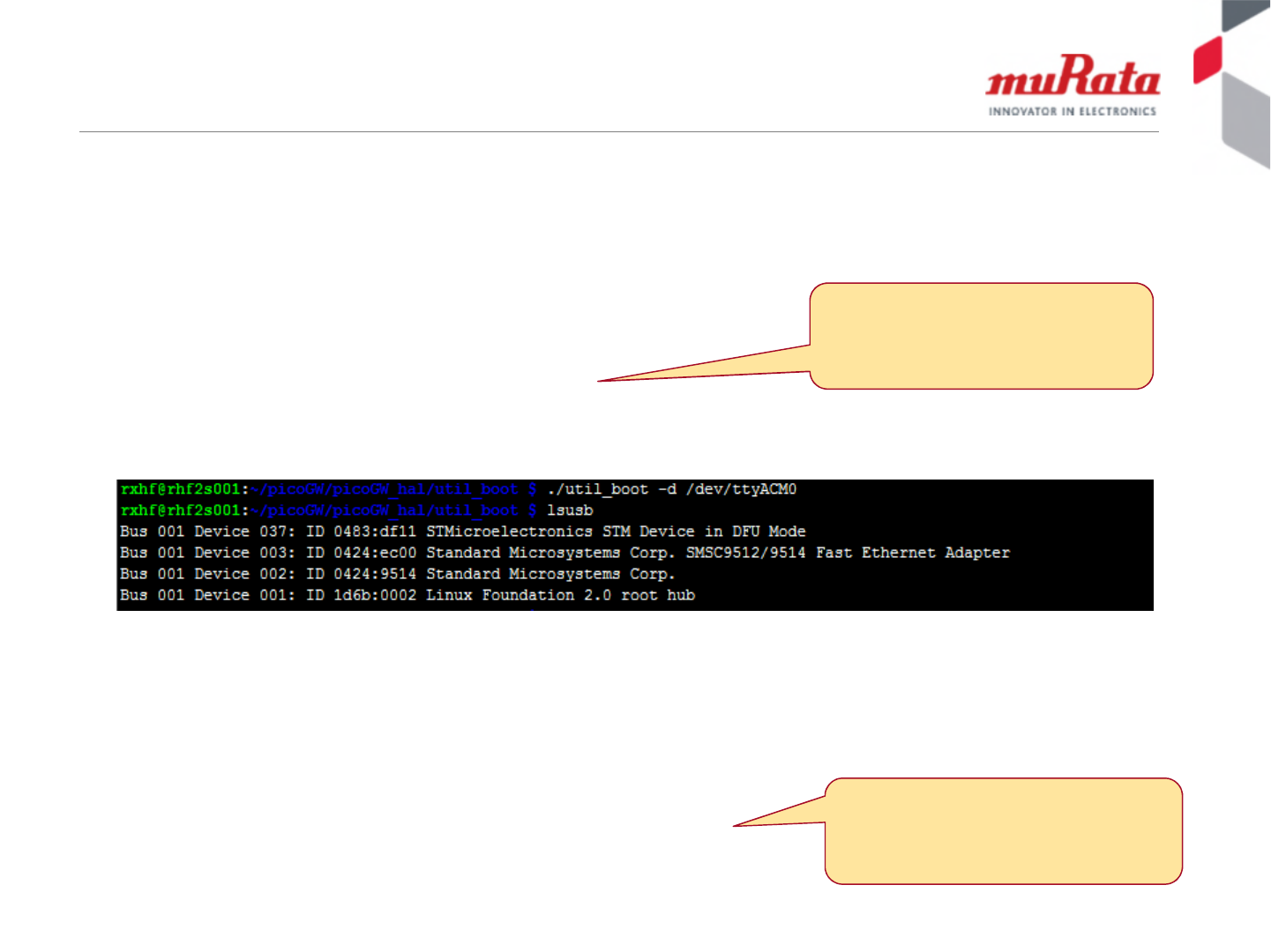
Enter DFU mode in Linux
•Enter DFU mode in Linux (SW method)
–lsusb
–cd ~/lora-net/picoGW_hal/util_boot
–./util_boot –d /dev/ttyACM0
–lsusb
•Start FW update:
–sudo /usr/local/bin/dfu-util –a 0 –D ~/lora-
net/picoGW_mcu/bin/PGW_new.dfu
ttyACM0 is the serial port device under
/dev, which is created after inserting
the USB able. It maybe different on
your platform.
The path and name of the fw file to be
flashed, can be different on your
platform.
17
Copyright © Murata Manufacturing Co., Ltd. All rights reserved. 22 March 2018
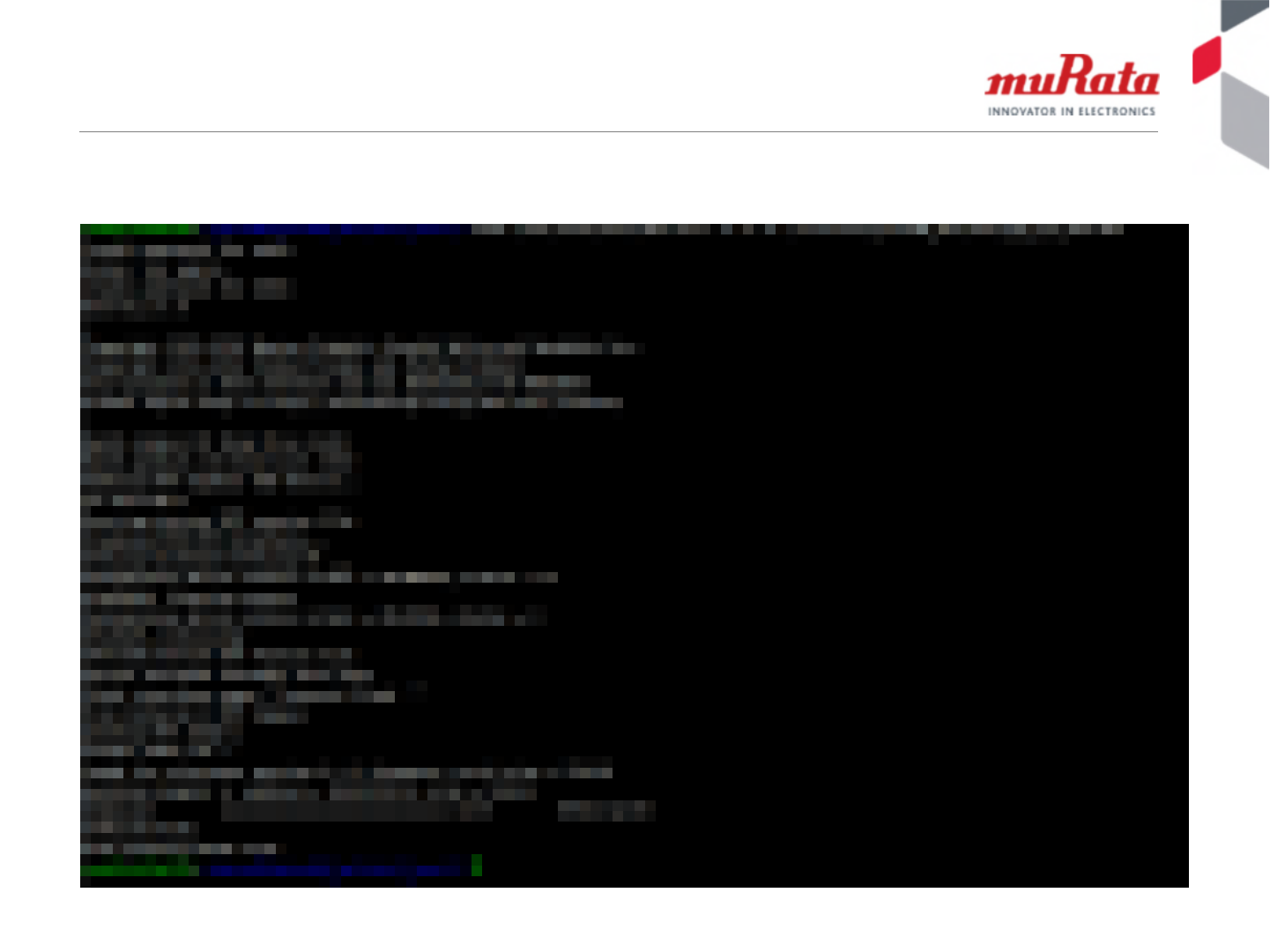
Screen shot of upgrading MCU FW…
Upgrade MCU FW in Linux

18
Copyright © Murata Manufacturing Co., Ltd. All rights reserved. 22 March 2018
Table of Contents
•Module Overview
•Module Interface Overview
•Adaptor Board Overview
•Methods to Update FW in Module
–From Linux Host (e.g. Raspberry Pi)
–Using ST-Link Cable & Tool
–Using ST Dfuse Tool from Windows PC
•Appendix: Adaptor Board Schematics

19
Copyright © Murata Manufacturing Co., Ltd. All rights reserved. 22 March 2018
The ST-Linker Tool – HW & SW
•When customers want to update the firmware, the
following tools can be used
–HW: STM32 ST-LINK (http://www.st.com/en/development-
tools/st-link-v2.html) or compatible
–SW: STM32 ST-LINK utility should be used to download the
firmware.
(http://www.st.com/content/st_com/en/products/embedded-
software/development-tool-software/stsw-link004.html)
20
Copyright © Murata Manufacturing Co., Ltd. All rights reserved. 22 March 2018
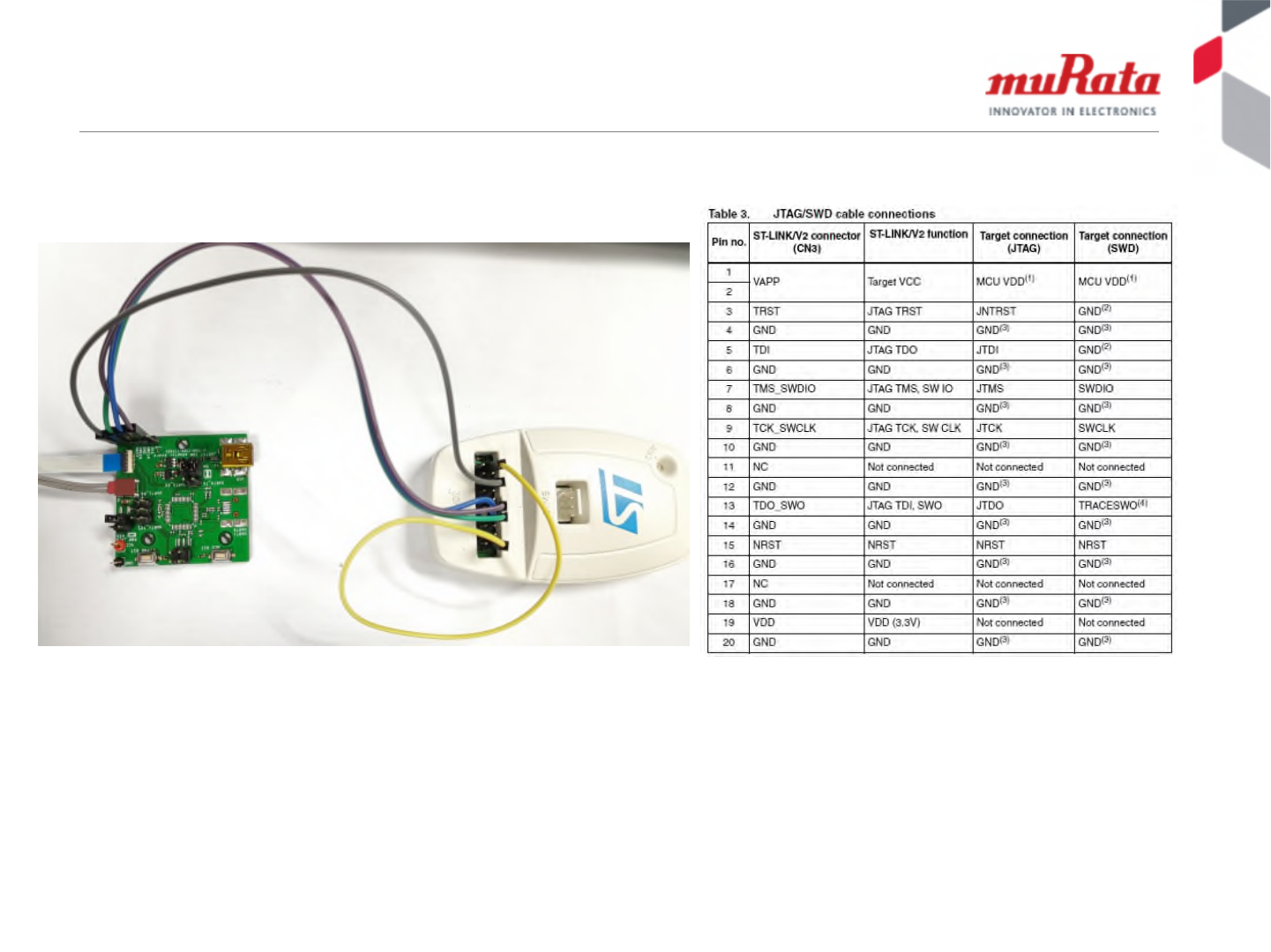
The ST-Linker and Adapter Connection
The following connection should be followed.
Adapter board ST Linker
SWCLK------------------------ Pin9
SWDIO------------------------- Pin7
NRST--------------------------- Pin15
GND---------------------------- GND
Pin1-----Pin19
Important: Pin 1 and Pin19 of ST linker should be short. Showed in the yellow line in the above picture

21
Copyright © Murata Manufacturing Co., Ltd. All rights reserved. 22 March 2018
Table of Contents
•Module Overview
•Module Interface Overview
•Adaptor Board Overview
•Methods to Update FW in Module
–From Linux Host (e.g. Raspberry Pi)
–Using ST-Link Cable & Tool
–Using ST Dfuse Tool from Windows PC
•Appendix: Adaptor Board Schematics

22
Copyright © Murata Manufacturing Co., Ltd. All rights reserved. 22 March 2018
DFU mode
•In case that customers don’t have ST-linker and
can not upgrade firmware with this method, DFU
mode can be used. There are two ways to enter
DFU mode.
–Option in PicoGW_UI (SW method)
–Boot0 pin (HW method)
23
Copyright © Murata Manufacturing Co., Ltd. All rights reserved. 22 March 2018
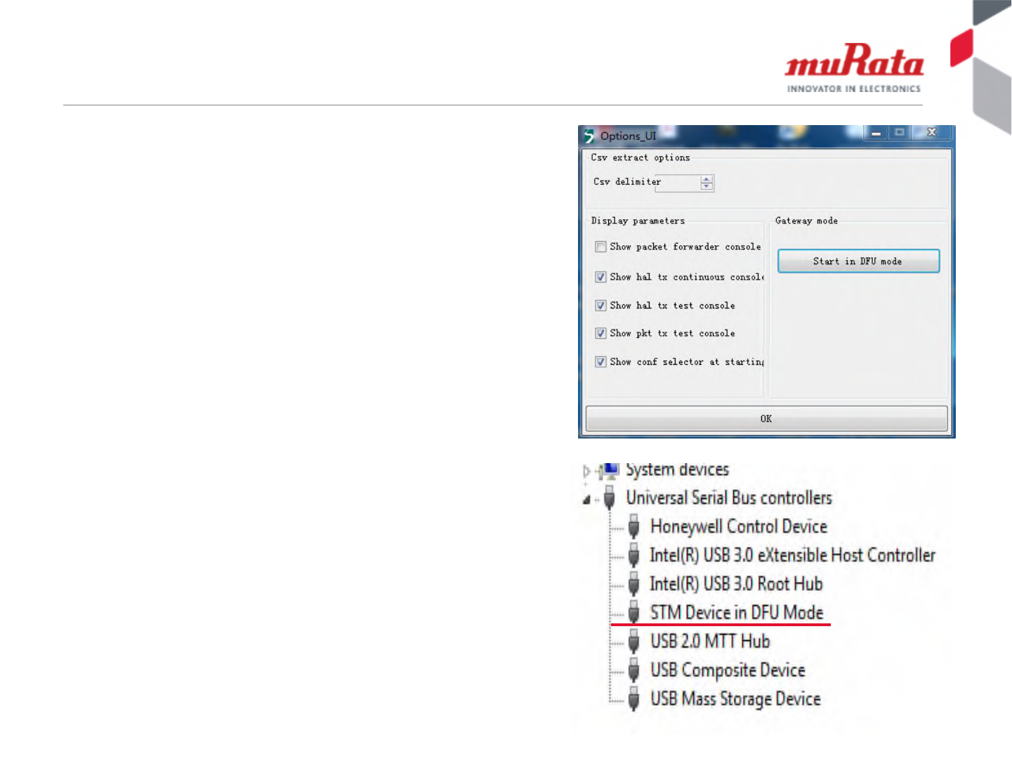
How to enter DFU mode (software method)
1. Install on Windows PC PicoGW_UI
v1.0.1 (available from Semtech)
2. Connect the module to PC via USB
3. Install STM virtual COM driver.
4. Execute PicoGW-UI.exe
5. Select options from menu.
6. Click Start in DFU mode (right-top
picture).
The module will reboot into DFU mode.
7. In the device manager (right-bottom
picture).
“STM Device in DFU mode” will appear
24
Copyright © Murata Manufacturing Co., Ltd. All rights reserved. 22 March 2018
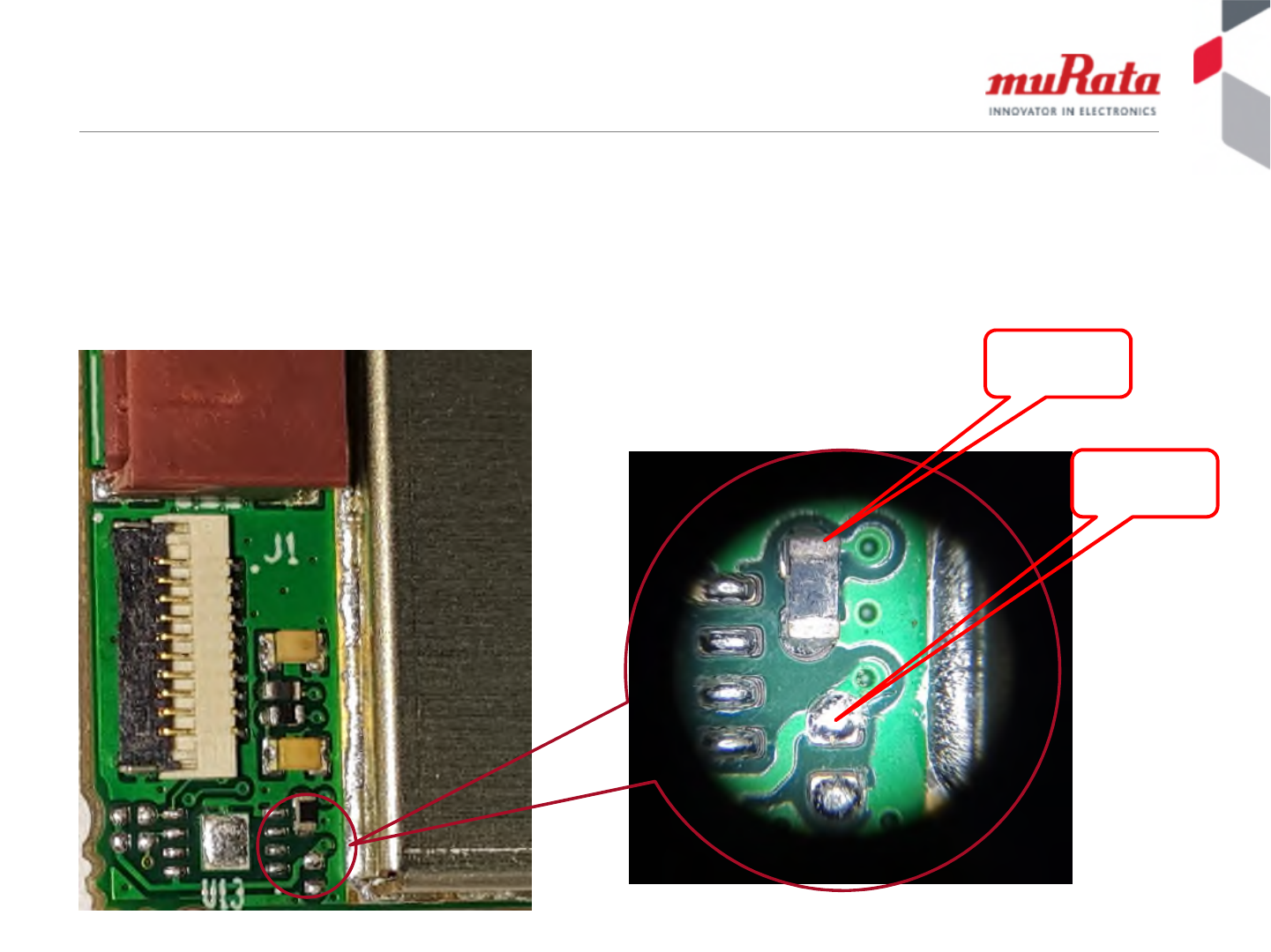
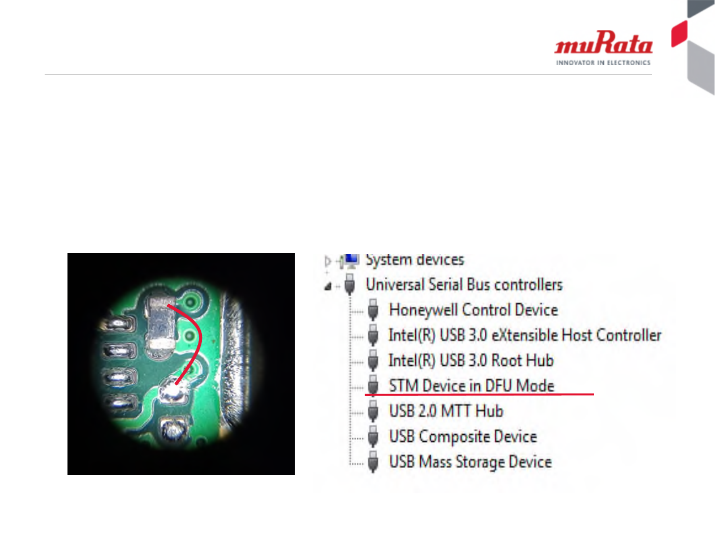
How to Enter DFU mode – HW Method (1)
In case there is no ST-linker tool and the module does not have a valid/working FW
loaded, following the steps here can put the module into DFU mode.
The pictures below show the location of the Boot0 pin of the MCU
• Boot0 = 0 when power up, normal working mode (default mode)
• Boot0 = 1 when power up, module into DFU mode
This pad is
3.3V
This pad is
Boot0 signal
25
Copyright © Murata Manufacturing Co., Ltd. All rights reserved. 22 March 2018
How to Enter DFU mode – HW Method (2)
1. Before power up the module, connect the 3.3V and Boot signal
as following picture using iron nipper or other conduct line.
2. Power up the module, then “STM Device in DFU mode” will
appear in the device manager.
3. After the module enters DFU mode, remove iron nipper or
conduct line used in #1 above.
26
Copyright © Murata Manufacturing Co., Ltd. All rights reserved. 22 March 2018
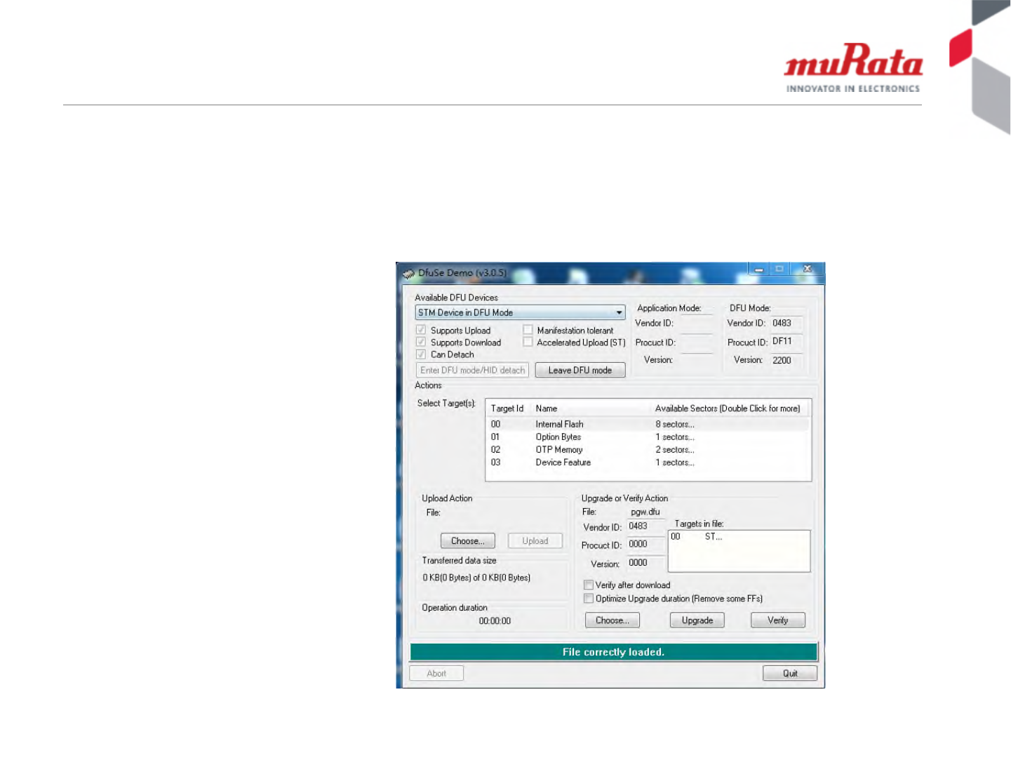
How to update MCU FW in DFU
1. Install ST DfuSe Demo tool in PC and open it.
• The tools is available from Semtech
2. Choose new MCU firmware and click upgrade.
3. The MCU firmware will be updated.

27
Copyright © Murata Manufacturing Co., Ltd. All rights reserved. 22 March 2018
Table of Contents
•Module Overview
•Module Interface Overview
•Adaptor Board Overview
•Methods to Update FW in Module
–From Linux Host (e.g. Raspberry Pi)
–Using ST-Link Cable & Tool
–Using ST Dfuse Tool from Windows PC
•Appendix: Adaptor Board Schematics
28
Copyright © Murata Manufacturing Co., Ltd. All rights reserved. 22 March 2018
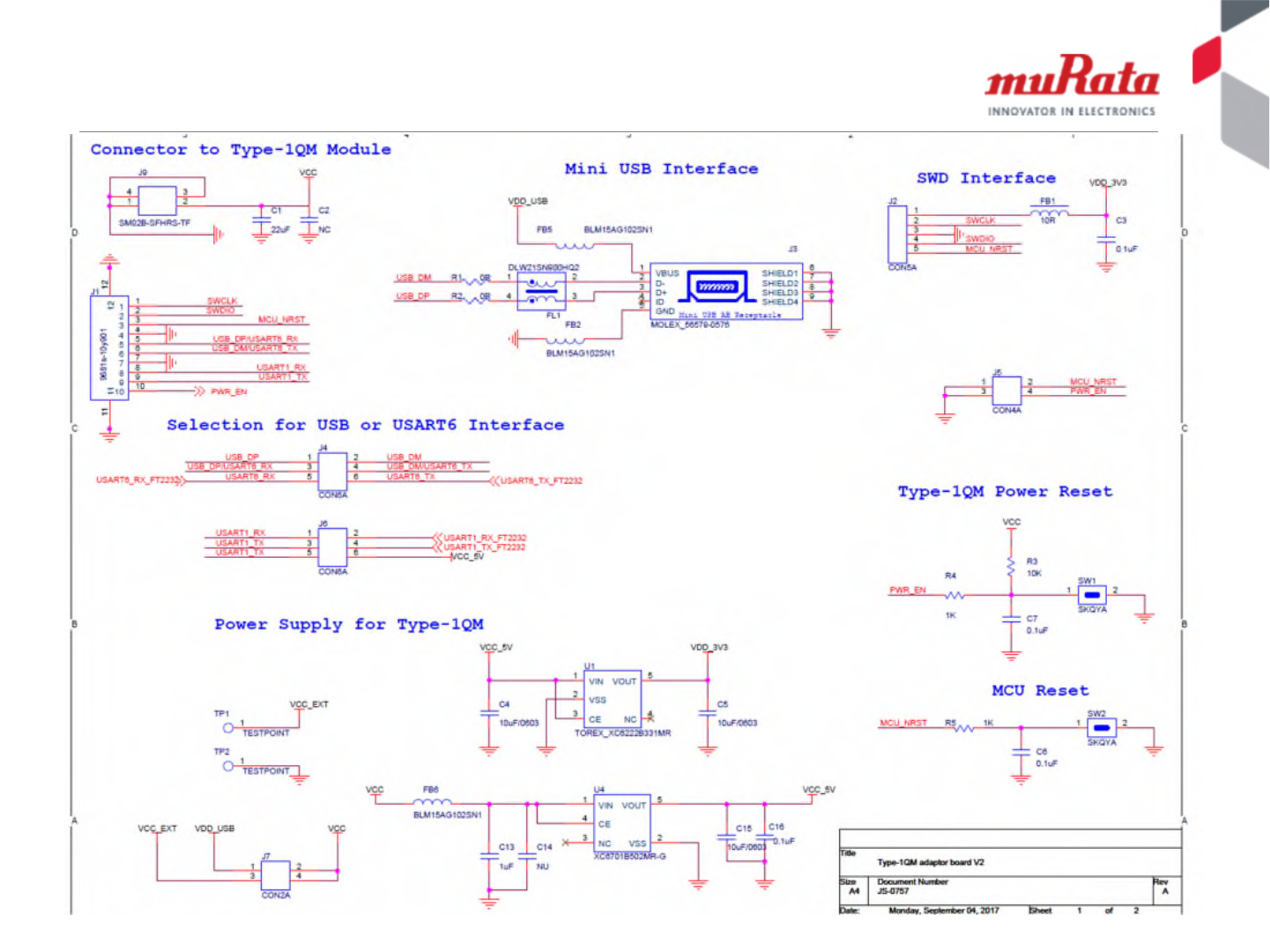
Schematic (1) of Adapter Board
29
Copyright © Murata Manufacturing Co., Ltd. All rights reserved. 22 March 2018
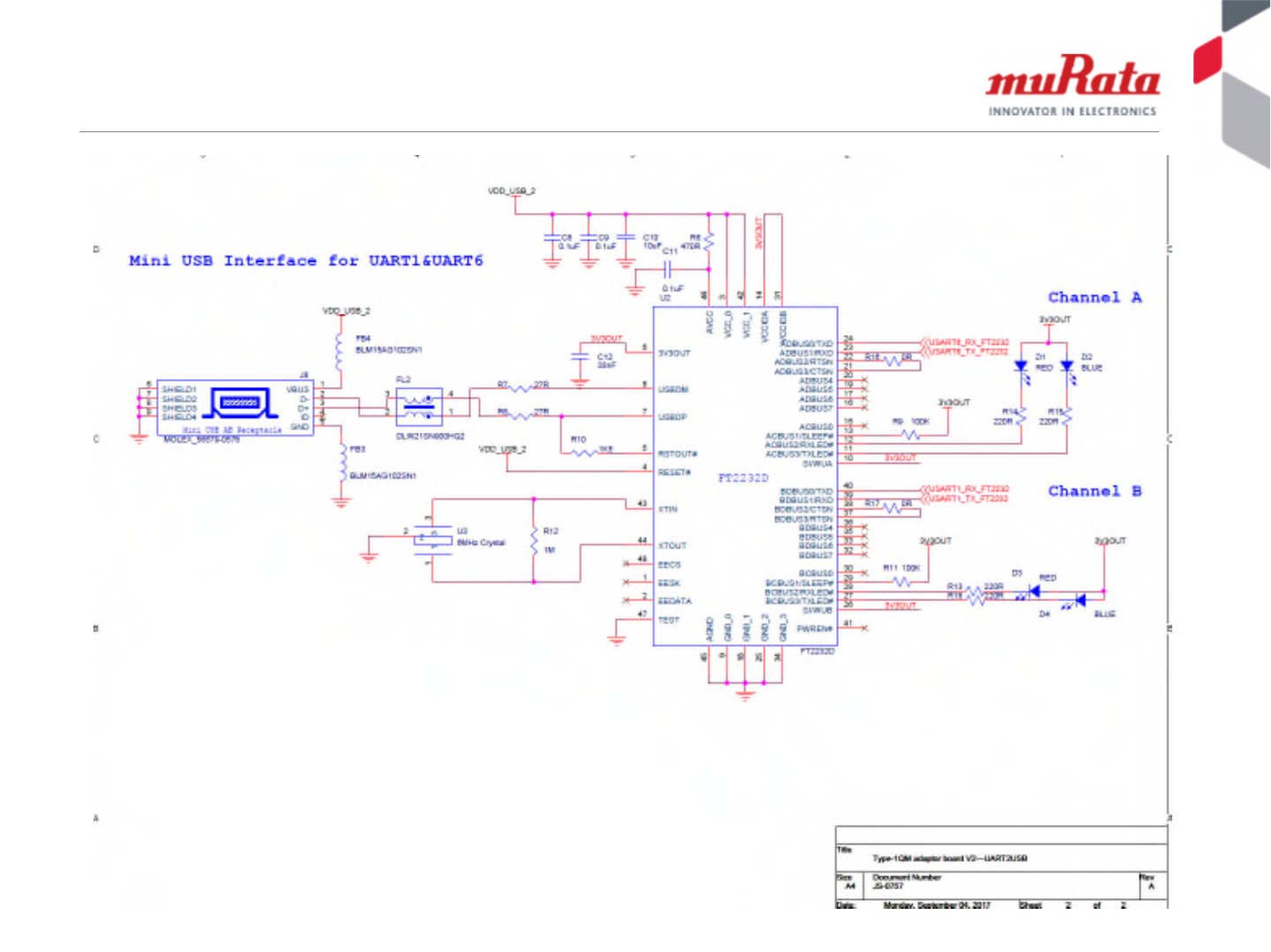
Schematic (2) of Adapter Board

30
Copyright © Murata Manufacturing Co., Ltd. All rights reserved. 22 March 2018
FCC Caution (1)
FCC Caution: Any changes or modifications not expressly approved by the party responsible for compliance could void the user's
authority to operate this equipment.
This device complies with Part 15 of the FCC Rules. Operation is subject to the following two conditions: (1) This device may not cause
harmful interference, and (2) this device must accept any interference received, including interference that may cause undesired
operation.
This device and its antenna(s) must not be co-located or operating in conjunction with any other antenna or transmitter.
IMPORTANT NOTE:
FCC Radiation Exposure Statement:
This equipment complies with FCC radiation exposure limits set forth for an uncontrolled environment. This equipment should be installed
and operated with minimum distance 25cm between the radiator & your body.
The module is limited to OEM installation ONLY.
This module is intended for OEM integrators under the following conditions:
This module is restricted to installation in products for use only in mobile and fixed applications.
The antenna(s) used for this transmitter must be installed to provide a separation distance of at least 25 cm from all persons.
The antenna(s) used for this transmitter must not transmit simultaneously with any other antenna or transmitter.
The OEM integrator is still responsible for
ensuring that the end-user has no manual instructions to remove or install module
the FCC compliance requirement of the end product, which integrates this module.
Appropriate measurements (e.g. 15 B compliance) and if applicable additional equipment authorizations (e.g. Verification, Doc) of the host
device to be addressed by the integrator/manufacturer.
The separate approval is required for all other operating configurations, including portable configurations with respect to Part 2.1093 and
different antenna configurations

31
Copyright © Murata Manufacturing Co., Ltd. All rights reserved. 22 March 2018
Guidance to the Host Manufacturer:
We hereby acknowledge our responsibility to provide guidance to the host manufacturer in the event that they require assistance for
ensuring compliance with the Part 15 Subpart B requirements.
The host manufacturer is responsible for additional testing to verify compliance as a composite system. When testing the host device for
compliance with the Part 15 Subpart B requirements, the host manufacturer is required to show compliance with the Part 15 Subpart B
while the transmitter module(s) are installed and operating. The modules should be transmitting and the evaluation should confirm that the
module’s intentional emissions are compliant (i.e. fundamental and out of band emissions) with the Radio essential requirements. The
host manufacturer must verify that there are no additional unintentional emissions other than what is permitted in the Part 15 Subpart B or
emissions are complaint with the Radio aspects.
The user manual of the end product should include
Any changes or modifications not expressly approved by the party responsible for compliance could void the user's authority to operate
this equipment.
the restriction of operating this device in indoor could void the user’s authority to operate the equipment.
This device and its antenna(s) must not be co-located or operating in conjunction with any other antenna or transmitter.
This equipment should be installed and operated with minimum distance 25cm between the radiator & your body.
The FCC part 15.19 statement: This device complies with part 15 of the FCC Rules. Operation is subject to the following two conditions:
(1) This device may not cause harmful interference, and (2) this device must accept any interference received, including interference that
may cause undesired operation.
Label of the end product:
The final end product must be labeled in a visible area with the following " Contains TX FCC ID: G95LORMOD01".
The end product shall bear the following 15.19 statement: This device complies with part 15 of the FCC Rules. Operation is subject to the
following two conditions: (1) This device may not cause harmful interference, and (2) this device must accept any interference received,
including interference that may cause undesired operation.
If the labelling area is considered too small and therefore it is impractical (smaller than the palm of the hand) to display the compliance
statement, then the statement may be placed in the user manual or product packaging.
FCC Caution (2)

32
Copyright © Murata Manufacturing Co., Ltd. All rights reserved. 22 March 2018
END