Technicolor Connected Home USA TCA200 Touch Screen Alarm Panel User Manual Home Installation Guide

Technicolor Connected Home USA LLC Touch Screen Alarm Panel Home Installation Guide

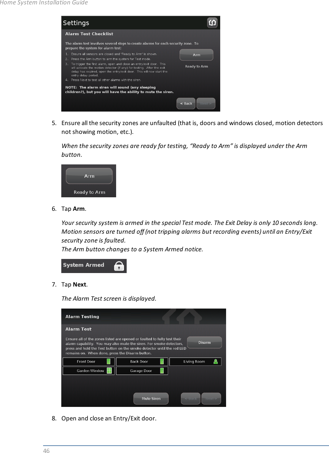
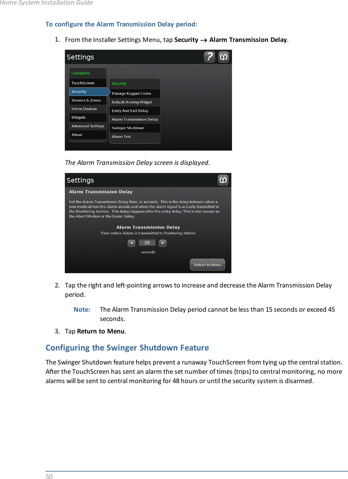
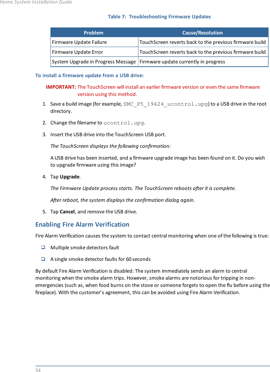
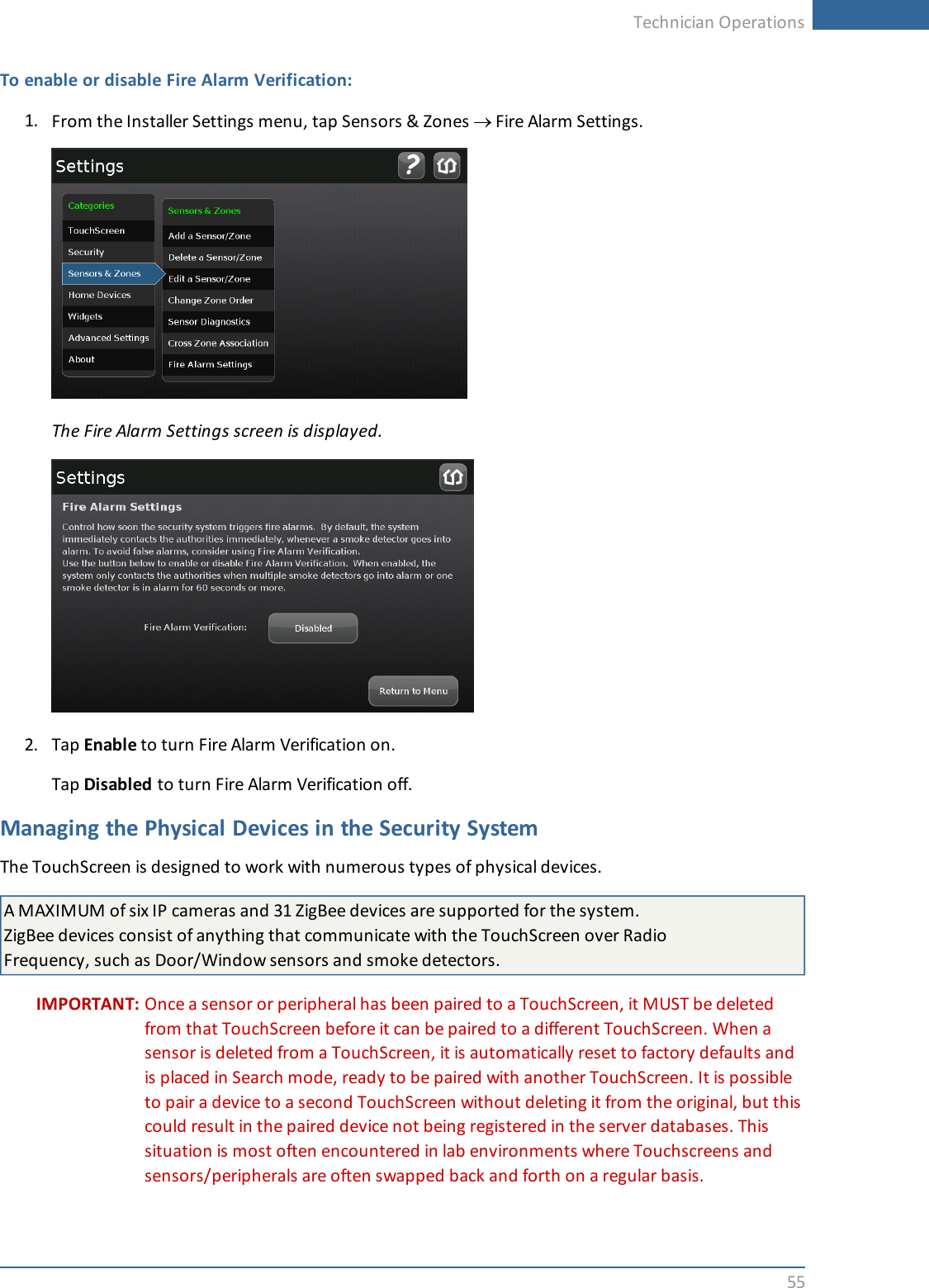
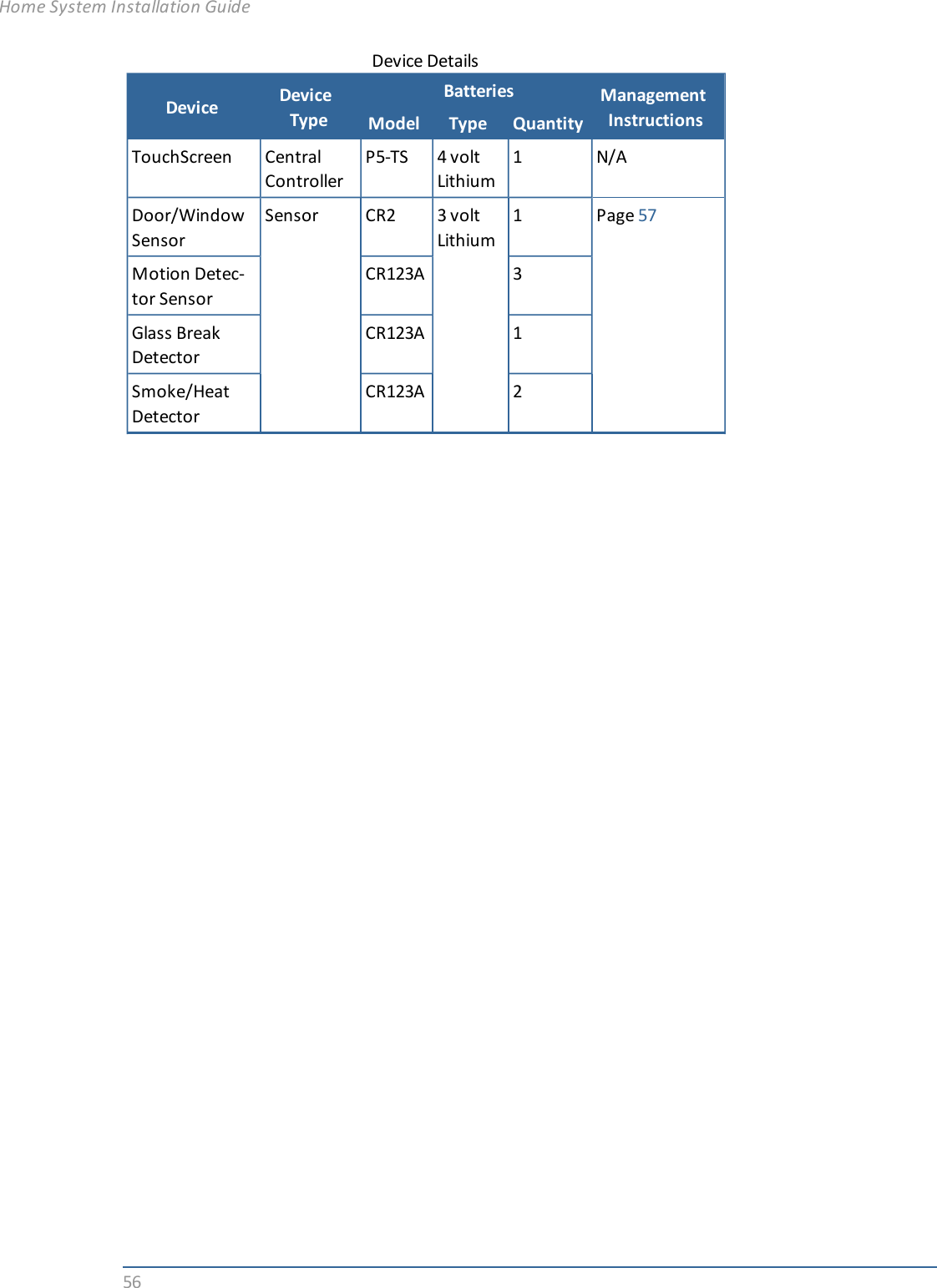
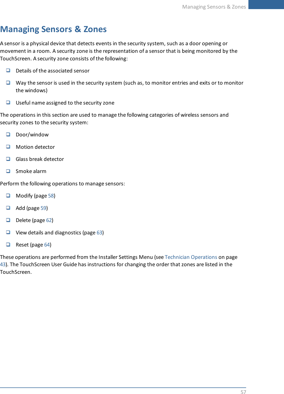
Installation Guide Part 2
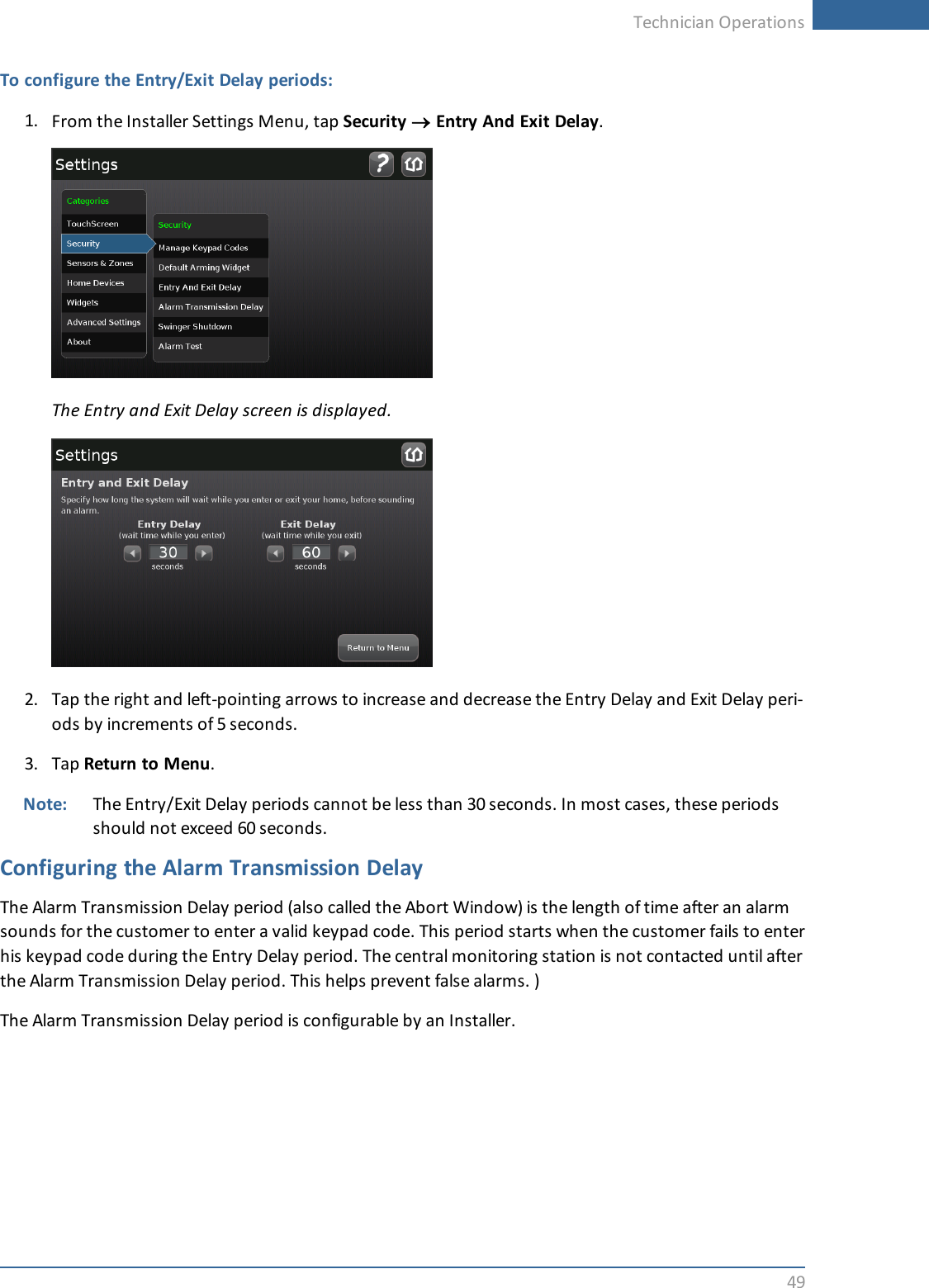
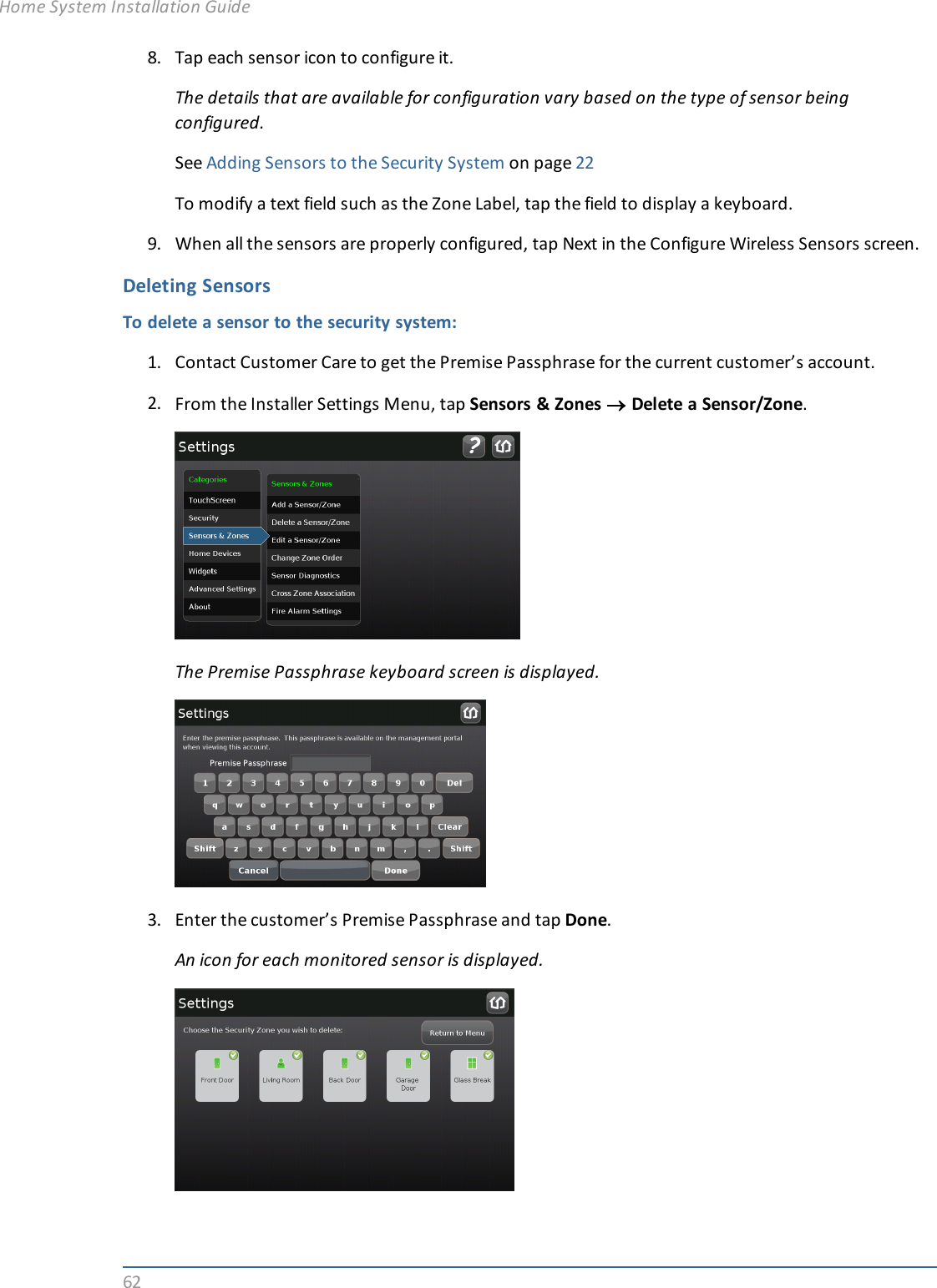
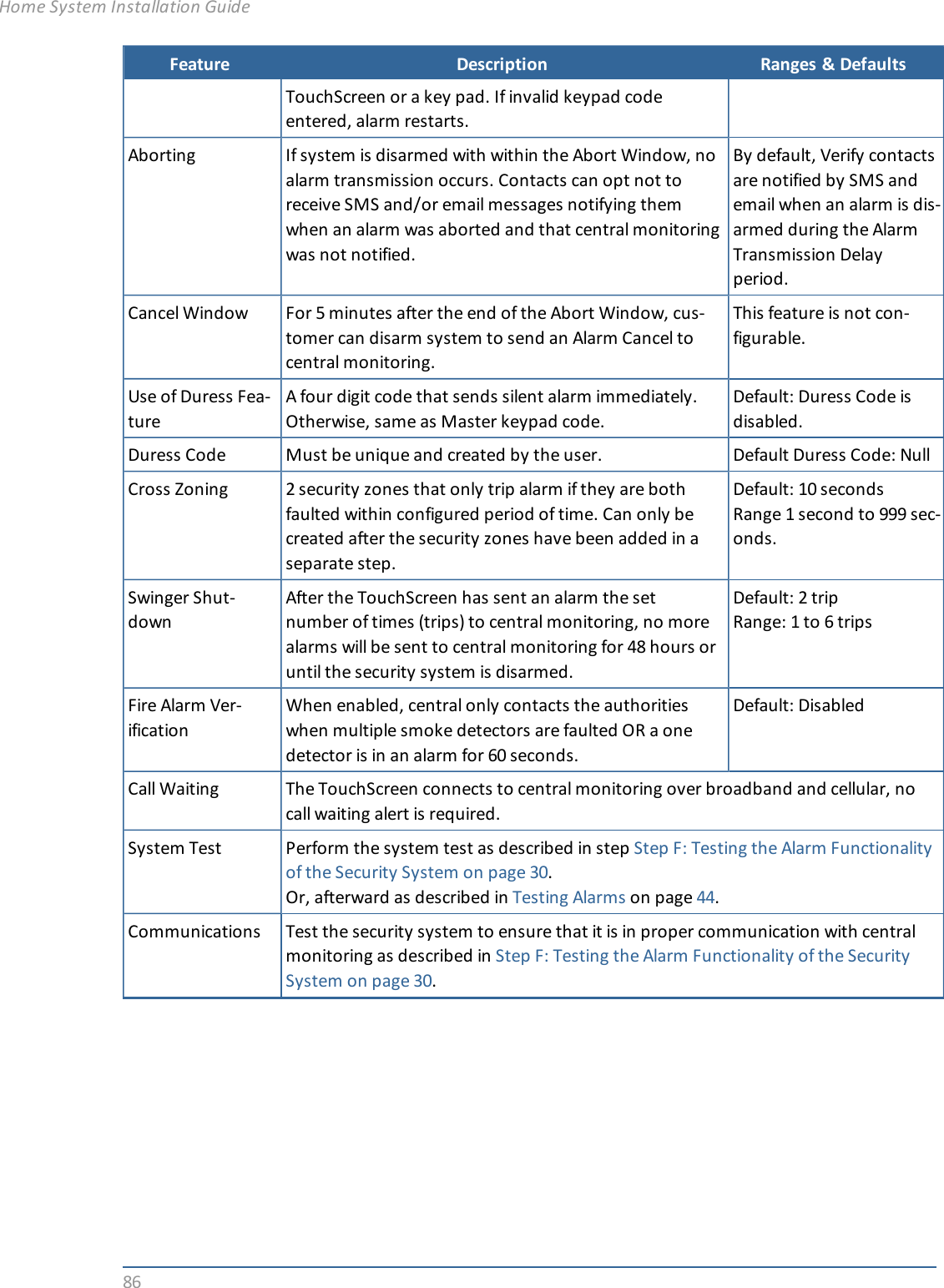
Technician Operations43Technician OperationsCustomers can use the Settings widget to access a variety of operations to configure and maintain theirsecurity system as described in the uControl TouchScreen User Guide. When an installer accesses theSettings widget with an Installer keypad code, they have access to the same operations as well otheroperations unavailable to a customer.Getting StartedTo access the Installers Settings menu:1. From the Home screen, tap the Settings widget.A keypad is displayed.2. Enter the Installers keypad code.Note: Not the customer’s Master keypad code.A keyboard screen is displayed.3. Enter your Technician Code and tap Done.
44The Installer Settings menu is displayed.The following Installer operations are available from the Installer Settings menu:Configure the Entry/Exit delay periods (page 48)Configure the Alarm Transmission delay (page 49)Configure the Swinger Shutdown feature (page 50)Reset the TouchScreen to factory defaults (page 51)Check for new firmware versions (page 52)Manage sensors and zones (page 57)Create cross-zone associations for sensors (page 67)Performing the RMA procedure (page 1)Resetting your managed router (see the TouchScreen User Guide )Both customers and Installers can test the alarm capabilities, by following the procedure described onpage 44.Testing AlarmsInstallers can test the alarm system without going through the entire activation process.To test alarms (after activation):1. Call the central monitoring and tell them you are about to test your system.2. From the Installers Settings widget (see page 43), tap Security ®Alarm Test.Home System Installation Guide
Technician Operations45The Alarm Test Options screen is displayed.3. To have your test alarms reported to central monitoring, tap Disabled.The button changes to Enabled. Your test alarms will be sent to central monitoring.Note: If the Enabled button is already displayed, tap Enabled to choose to have your testalarms NOT sent to central monitoring.IMPORTANT: If you enable Send Test Alarm Messages, contact your central monitoringstation and tell them you are testing your system.4. Ensure all the security zones are unfaulted (that is, doors and windows closed, motion detectorsnot showing motion, etc.).The Alarm Test Checklist is displayed.
465. Ensure all the security zones are unfaulted (that is, doors and windows closed, motion detectorsnot showing motion, etc.).When the security zones are ready for testing, “Ready to Arm” is displayed under the Armbutton.6. Tap Arm.Your security system is armed in the special Test mode. The Exit Delay is only 10 seconds long.Motion sensors are turned off (not tripping alarms but recording events) until an Entry/Exitsecurity zone is faulted.The Arm button changes to a System Armed notice.7. Tap Next.The Alarm Test screen is displayed.8. Open and close an Entry/Exit door.Home System Installation Guide
Technician Operations47The Entry Delay period starts (default 30 seconds). The TouchScreen begins beeping once persecond. The beeping speeds up to twice per second in the last 10 seconds of the Entry Delayperiod. The motion detectors are turned on.Note: To mute the siren, tap Mute Siren. This is not recommended. Ensuring that your sirenis in working order is an important part of the test.After the end of the Entry Delay period ends, the siren sounds (unless you muted it) and theEntry/Exit zone you faulted is marked with an alarm tag.9. Fault each additional alarm as described in the following table and ensure that it is marked asalarm.Sensor Testing ProcessDoor/Window Open and close the door or window.Motion Detec-torAvoid the motion detector’s view for three minutes after arming the system,then walk in front of it.Smoke Detec-torPress and hold the sensor’s “Test” button until the siren sounds, approx. 10secondsGlass BreakDetectorUse a glass break simulator.Sensor Testing OperationsThe TouchScreen notes that each sensor communicated an event to the TouchScreen andinitiated an alarm.
4810. After all the alarms have been faulted and the system has noted it, tap Disarm.11. Tap Next.The Review Alarms screen is displayed showing a history of the zones in your system.12. Review the zone event history.13. Ensure you have received any configured alerts via email or SMS.14. If you enabled Send Test Alarm Messages, contact the central monitoring station Test number toensure that they received all the generated alarms. If all the alarms were received successfully, tellthem that you are no longer testing alarms.15. Tap Next to return to the Settings menu.Configuring the Entry/Exit Delay PeriodsThe Entry Delay period is the amount of time from an Entry/Exit sensor being faulted until an alarmsounds. The customer has until the end of the Entry Delay period to enter a valid keypad code. There isno Entry Delay period for Perimeter type sensors (such as window sensors or non-entry door sensors).There is an audible beeping during the Entry Delay period. This beeping sound is not configurable andcannot be muted.The Exit Delay period is the amount of time that starts when the security system is armed. The customerhas this period of time to exit through an Entry/Exit sensor doorway. If the customer does not exit duringthis period, the system cannot be armed in Arm Away state. The system will arm in Arm Stay state. Thereis an audible beeping during the Exit Delay (once per second) that speeds up during the last 10 seconds ofthe Exit Delay (twice per second).The Entry/Exit Delay periods are configurable by an Installer.Home System Installation Guide
Technician Operations49To configure the Entry/Exit Delay periods:1. From the Installer Settings Menu, tap Security ®Entry And Exit Delay.The Entry and Exit Delay screen is displayed.2. Tap the right and left-pointing arrows to increase and decrease the Entry Delay and Exit Delay peri-ods by increments of 5 seconds.3. Tap Return to Menu.Note: The Entry/Exit Delay periods cannot be less than 30 seconds. In most cases, these periodsshould not exceed 60 seconds.Configuring the Alarm Transmission DelayThe Alarm Transmission Delay period (also called the Abort Window) is the length of time after an alarmsounds for the customer to enter a valid keypad code. This period starts when the customer fails to enterhis keypad code during the Entry Delay period. The central monitoring station is not contacted until afterthe Alarm Transmission Delay period. This helps prevent false alarms. )The Alarm Transmission Delay period is configurable by an Installer.
50To configure the Alarm Transmission Delay period:1. From the Installer Settings Menu, tap Security ®Alarm Transmission Delay.The Alarm Transmission Delay screen is displayed.2. Tap the right and left-pointing arrows to increase and decrease the Alarm Transmission Delayperiod.Note: The Alarm Transmission Delay period cannot be less than 15 seconds or exceed 45seconds.3. Tap Return to Menu.Configuring the Swinger Shutdown FeatureThe Swinger Shutdown feature helps prevent a runaway TouchScreen from tying up the central station.After the TouchScreen has sent an alarm the set number of times (trips) to central monitoring, no morealarms will be sent to central monitoring for 48 hours or until the security system is disarmed.Home System Installation Guide
Technician Operations51To configure the swinger shutdown:1. From the Installer Settings Menu, tap Security ®Swinger Shutdown.The Swinger Shutdown Settings screen is displayed.2. Tap the right and left-pointing arrows to increase and decrease the number of swinger shutdowntrips (Maximum Trips).Note: The number of trips cannot be less than 1 or exceed 6.3. Tap Swinger Shutdown Enabled to disable this feature.Tap Swinger Shutdown Disabled to enable this feature.Resetting the TouchScreen to Factory DefaultsWhen an activated TouchScreen is reset to factory defaults, the customer’s account must also be resetby Customer Care in order for it to be reactivated.To reset the TouchScreen:1. Ensure you have the premise passphrase for the account.2. From the Installer Settings Menu, tap Advanced Settings ®Reset to Factory Defaults.
52The Reset Touchscreen to Factory Defaults screen is displayed.3. Tap Reset to Factory Defaults.The Keypad screen is displayed.4. Enter the Installer keypad code.The Keyboard screen is displayed.5. Enter the PREMISE PASSPHRASE for the current account.The device resets and the Installation screen is displayed.To activate the system again:1. Contact Customer Care to have the customer’s account reset.2. Follow the steps starting on page 13 to activate the system again.Checking for New Firmware Updates for the TouchScreenYou can have a TouchScreen look for an available update on the server or install an update from a USBdrive (see page 54).Home System Installation Guide
Technician Operations53To check for a firmware update on the server:1. From the Installer Settings Menu, tap Advanced Settings ®Check for Firmware Update.The Checking for Firmware Upgrade screen is displayed. The TouchScreen immediately checks fornewer firmware updates that are available to be installed on the device’s hardware version.If a newer firmware version is available for the current device’s hardware version, an UpgradeFirmware button is displayed.2. Tap Upgrade Firmware to download and install the new firmware version (the system will reboot.
54Problem Cause/ResolutionFirmware Update Failure TouchScreen reverts back to the previous firmware buildFirmware Update Error TouchScreen reverts back to the previous firmware buildSystem Upgrade in Progress Message Firmware update currently in progressTable 7: Troubleshooting Firmware UpdatesTo install a firmware update from a USB drive:IMPORTANT: The TouchScreen will install an earlier firmware version or even the same firmwareversion using this method.1. Save a build image (for example, SMC_P5_19424_ucontrol.upg) to a USB drive in the rootdirectory.2. Change the filename to ucontrol.upg.3. Insert the USB drive into the TouchScreen USB port.The TouchScreen displays the following confirmation:A USB drive has been inserted, and a firmware upgrade image has been found on it. Do you wishto upgrade firmware using this image?4. Tap Upgrade.The Firmware Update process starts. The TouchScreen reboots after it is complete.After reboot, the system displays the confirmation dialog again.5. Tap Cancel, and remove the USB drive.Enabling Fire Alarm VerificationFire Alarm Verification causes the system to contact central monitoring when one of the following is true:Multiple smoke detectors faultA single smoke detector faults for 60 secondsBy default Fire Alarm Verification is disabled: The system immediately sends an alarm to centralmonitoring when the smoke alarm trips. However, smoke alarms are notorious for tripping in non-emergencies (such as, when food burns on the stove or someone forgets to open the flu before using thefireplace). With the customer’s agreement, this can be avoided using Fire Alarm Verification.Home System Installation Guide
Technician Operations55To enable or disable Fire Alarm Verification:1. From the Installer Settings menu, tap Sensors & Zones ®Fire Alarm Settings.The Fire Alarm Settings screen is displayed.2. Tap Enable to turn Fire Alarm Verification on.Tap Disabled to turn Fire Alarm Verification off.Managing the Physical Devices in the Security SystemThe TouchScreen is designed to work with numerous types of physical devices.A MAXIMUM of six IP cameras and 31 ZigBee devices are supported for the system.ZigBee devices consist of anything that communicate with the TouchScreen over RadioFrequency, such as Door/Window sensors and smoke detectors.IMPORTANT: Once a sensor or peripheral has been paired to a TouchScreen, it MUST be deletedfrom that TouchScreen before it can be paired to a different TouchScreen. When asensor is deleted from a TouchScreen, it is automatically reset to factory defaults andis placed in Search mode, ready to be paired with another TouchScreen. It is possibleto pair a device to a second TouchScreen without deleting it from the original, but thiscould result in the paired device not being registered in the server databases. Thissituation is most often encountered in lab environments where Touchscreens andsensors/peripherals are often swapped back and forth on a regular basis.
56Device DeviceTypeBatteries ManagementInstructionsModel Type QuantityTouchScreen CentralControllerP5-TS 4 voltLithium1 N/ADoor/WindowSensorSensor CR2 3 voltLithium1 Page 57Motion Detec-tor SensorCR123A 3Glass BreakDetectorCR123A 1Smoke/HeatDetectorCR123A 2Device DetailsHome System Installation Guide
Managing Sensors & Zones57Managing Sensors & ZonesA sensor is a physical device that detects events in the security system, such as a door opening ormovement in a room. A security zone is the representation of a sensor that is being monitored by theTouchScreen. A security zone consists of the following:Details of the associated sensorWay the sensor is used in the security system (such as, to monitor entries and exits or to monitorthe windows)Useful name assigned to the security zoneThe operations in this section are used to manage the following categories of wireless sensors andsecurity zones to the security system:Door/windowMotion detectorGlass break detectorSmoke alarmPerform the following operations to manage sensors:Modify (page 58)Add (page 59)Delete (page 62)View details and diagnostics (page 63)Reset (page 64)These operations are performed from the Installer Settings Menu (see Technician Operations on page43). The TouchScreen User Guide has instructions for changing the order that zones are listed in theTouchScreen.
58Maintaining SensorsModifying Sensor DetailsTo modify the details for a sensor/zone in the security system:1. From the Installer Settings Menu, tap Sensors & Zones ®Edit a Sensor/Zone.A series of icons are displayed that represent each installed sensor being monitored by thesecurity system.2. Tap the icon for the sensor that you want to modify.The Edit Sensors/Zone—Modify Zone Settings wizard is displayed.Home System Installation Guide
Managing Sensors & Zones593. Tap a field to change it.Touching menu fields display a menu of items. Touching text fields displays a keyboard screen tochange a label.4. Tap Next to move through the wizard.5. Tap Return to Menu when the sensor modifications are complete.Adding SensorsTo add a sensor to the security system:A sensor must meet the following requirements before it can be added to the security system:DefaultedNot currently paired with another TouchScreen deviceNote: To unpair a sensor from the current TouchScreen, you must delete it (see 62).Currently in Search mode1. From the Installer Settings Menu, tap Sensors & Zones ®Add a Sensor/Zone.The Locating Wireless Sensors screen is displayed.
602. Ensure each sensor to be added to the TouchScreen is in Search mode.See the sensor installation documentation for how to tell if a sensor is in Search mode, it is not inSearch mode, and how to restart Search mode if it is not.3. Tap Next.A Stop button is displayed on the Locating Wireless Sensors screen. The TouchScreen searches forsensors that are available to be added. As sensors are found, a grayed icon is displayed for thatsensor.4. Fault each found sensor to pair it to the TouchScreen.For example, for Door/Window sensors, separate the magnet and reed switch to mimic a doorbeing opened.As sensors are found, a grayed icon is displayed for that sensor.Home System Installation Guide
Managing Sensors & Zones61The icon for each sensor is undarkened as it is faulted and the TouchScreen beeps. The sensor ispaired to the TouchScreen.5. Determine that all the sensors have been located by the TouchScreen.6. When all the sensors are found and paired, tap Stop.The system notes the number of wireless sensors found and paired.7. Tap Next.The Configure Wireless Sensors screen is displayed.
628. Tap each sensor icon to configure it.The details that are available for configuration vary based on the type of sensor beingconfigured.See Adding Sensors to the Security System on page 22To modify a text field such as the Zone Label, tap the field to display a keyboard.9. When all the sensors are properly configured, tap Next in the Configure Wireless Sensors screen.Deleting SensorsTo delete a sensor to the security system:1. Contact Customer Care to get the Premise Passphrase for the current customer’s account.2. From the Installer Settings Menu, tap Sensors & Zones ®Delete a Sensor/Zone.The Premise Passphrase keyboard screen is displayed.3. Enter the customer’s Premise Passphrase and tap Done.An icon for each monitored sensor is displayed.Home System Installation Guide
Managing Sensors & Zones634. Tap the sensor icon to delete its sensors.A confirmation dialog is displayed:Deleting a zone cannot be undone. Are you sure you want to delete the<zone name> zone?5. Tap Yes.The sensor icon is deleted. The sensor is no longer being monitored by the security system.6. Fault the sensor to have it reset to factory default and placed in Search mode to be re-added to aTouchScreen.Viewing Sensor DetailsTo view details and diagnostic information about a sensor:1. From the Installer Settings Menu, tap Sensors & Zones ®Sensor Diagnostics.An icon for each monitored sensor is displayed.2. Tap the sensor icon to view its diagnostics.The details about the sensor are displayed.
64The following information is displayed about the sensor and security zone:Sensor serial number and type (Door/Window, smoke detector, etc.)Sensor signal strength detected by the TouchScreenSecurity zone details such as its Display Icon and its function (Entry/Exit, Perimeter, etc.)Resetting Sensors to Factory DefaultWhen a sensor is originally removed from its packaging, it is already in factory default mode. When youinstall the battery as described in the documentation, it will immediately begin searching for aTouchScreen with which it can pair.To reset a sensor that has already been added to a TouchScreen and place it in Search mode, delete it asdescribed in its included documentation.In the rare event that you need to force default a sensor that is not paired to a nearby TouchScreen, seethe following pages in each case:Door/window sensors—page 65Glass break detector—page 65Motion detector—page 66Smoke detector—page 67Home System Installation Guide
Managing Sensors & Zones65To force default a door/window sensor:1. Find the locking mechanism on the bottom of theSMCDW01-Z.2. Holding the SMCDW01-Z in one hand, carefully insert thetip of a screwdriver into the locking mechanism.3. Push lightly upwards from the back of the SMCDW01-Z until the back plateseparates from the sensor.4. Remove the battery.5. While pressing and holding the tamper switch, insert the battery into theSMCDW01-Z, with the positive (+) end oriented towards the tamperswitch. The front panel LED goes ON.6. After 1 second, release the tamper switch. The LED blinks green.7. Replace the SMCDW01-Z back plate.To force default a glass break detector:1. Remove the cover from the glass break detector.2. Remove the battery.3. While pressing and holding the tamper switch, insert the battery into the glass break detector.The front panel LED goes ON.
664. After 1 second, release the tamper switch. The LED blinks green.5. Replace the glass break detector cover.To force default a motion detector:1. Remove the back cover from the motion detector.2. Remove the batteries.3. Remove the front cover.4. While pressing and holding the tamper switch, insert a single battery into the motion detector.The front panel LED goes ON.5. After 1 second, release the tamper switch. The LED blinks green.6. Replace the front cover and all the batteries to the motion detector.7. Replace the back cover.To force default a smoke detector:1. Twist the back cover of the smoke detector to remove it from the device.2. Remove the batteries.3. Use a screwdriver to release the securing tabs that secure the front cover and remove it.Home System Installation Guide
Managing Sensors & Zones67The tamper switch is located on the circuit board that is at a 90º angle to the casing plane.4. While pressing and holding the tamper switch, insert a single battery into the smoke detector. TheLED goes ON.5. After 1 second, release the tamper switch. The LED blinks green.6. Replace the front cover.Replace all the batteries to the smoke detector and the back cover.Managing Cross-Zone AssociationsA cross-zone association requires the following for an alarm to be tripped:Two specific sensors are faultedThe sensors are faulted in a particular orderThe sensors are faulted within a set time period
68For example, you can require that a door be opened and that a motion sensor detect movement in orderfor an alarm to be tripped. This can be useful way to avoid a pet inadvertently setting off a motion sensoralarm.If a Cross-Zone association needs to be modified, delete it (page 69) and create a new one.Things to Know about cross-zone associations:Neither sensor in a cross-zone association will trip an alarm individually ever, in any situation.The associated zones will not trip an alarm if they are faulted in the wrong order.You cannot associate a single sensor in more than one cross-zone association.IMPORTANT: Do not use a Cross-Zone association for an Entry/Exit security zone. A Cross-Zoneassociation will override the Entry Delay for such exits.To create a cross-zone association for two sensors:1. From the Installer Settings Menu, tap Sensors & Zones ®Cross Zone Association.The Cross Zone Associations screen is displayed.2. Tap Add.The Add Cross-Zone Associations screen is displayed.Home System Installation Guide
Managing Sensors & Zones693. Tap a sensor/security zone listed in the First Zone column.4. Tap a different sensor/security listed in the Second Zone column.5. In the Cross Zone Timeout field, tap the arrows to set the number of seconds that the system willwait after ONE of the sensors is faulted to see if the OTHER sensor is faulted.6. Tap Save to create the cross-zone association.To delete a cross-zone association for two sensors:1. From the Installer Settings Menu, tap Sensors & Zones ®Cross Zone Association.The Cross Zone Associations screen is displayed listing each cross-zone association.
702. Tap Delete next to a cross-zone association.The cross-zone association is removed.Swapping the Security Network RouterThis section describes how to replace the security network router with a new one. Also, use thisprocedure to repair the TouchScreen with the security network router after you have reset the routerfactory defaults.To replace a TouchScreen with a new one:1. If Sercomm cameras are installed to the security system, upgrade the camera firmware to version1.0.07 or later.2. Delete the cameras from the TouchScreen as described on page 1.3. Reset the security network router to factory defaults; that is, the router to which the TouchScreenis most directly connected.4. If you are swapping the current router for a new one, unplug the router and disconnect it from theTouchScreen (if it is connected by Ethernet).5. Reboot your broadband modem.6. Reconnect the new router in place of the original. Ensure it is set to factory defaults. Ensure thenew router is fully operational with Wi-Fi enabled.7. For installing the Netgear router in a non-standard installation where the security network routeris placed behind the service provider’s modem/router, place the router into the DMZ of the of themodem/router.8. From the Settings Menu, tap Advanced Settings®Connectivity.The Connectivity Screen is displayed.Home System Installation Guide
Managing Sensors & Zones719. Select Reset Router From Factory.The Connectivity menu is displayed.10. Tap Next.The Connectivity screen displays the type of Internet router to which the TouchScreen willconnect.
7211. Tap the type of router the TouchScreen will use and tap Next.The Connectivity Setup screen displays options for connecting to the router/modem.The following options are displayed:Router — Connect to the router/modem wirelessly)Ethernet with Router — Connect to the router/modem using an IEEE 802.3 Ethernet cable12. Tap the method for the TouchScreen to connect to the router/modem and tap Next.If Router was selected, the Router Connection Checklist is displayed.If Ethernet with Router was selected, the Ethernet Connection Checklist is displayed.Home System Installation Guide
Managing Sensors & Zones7313. Follow the instructions on the Connection Checklist screen.14. Reset the router/modem to factory defaults and then reboot it.For wireless connectivity, see page 76.For wired connectivity, see page 76.For wireless connectivity:1. Tap Next.The TouchScreen locates all the available wireless routers in range, and displays their MACaddress.
742. Check the MAC address for the router/modem to which the TouchScreen must connect (usuallylocated at the back of the device).3. Tap the MAC address for the correct router.4. Tap Next.The Configuring and Securing the Router screen is displayed as the TouchScreen establishes afirm connection with the router/modem, the Broadband servers, and the Cellular connectivityservers.Note: This step takes longer than it does during Activation. The items on this screen will varybased on your particular router.Home System Installation Guide
Managing Sensors & Zones755. Tap Reboot TouchScreen.6. Re-install the cameras as described on page 1.For cabled connectivity:1. Tap Next.The Ethernet Adapters screen is displayed. The TouchScreen locates and secures the Ethernetadapter.Note: This step takes longer than it does during Activation. The items on this screen will varybased on your particular router.2. Wait a few minutes for the router/modem to reassign IP addresses.
76Note: If the system cannot find the proper router, ensure it has been reset to factorydefault.The Reset Router From Factory Screen displays a Reboot TouchScreen button.3. Tap Reboot TouchScreen.4. Re-install the cameras as described on page 1.Troubleshooting Router SwappingProblem Cause SolutionFirmwareUpdate ProblemSee Troubleshooting Firmware Updates on page 54.Invalid code User entered an invalid key-pad code.Use the Settings widget to add,edit, and delete keypad codesSystem notready to ArmDoor or window is open. Open the Security widget andcheck the security zones, door orwindow might be openSystem will notArmUser entered an invalid key-pad code when attempting toarm the system.Reattempt to enter the securitycode.Use the Settings widget to add,edit, and delete keypad codesContact Customer Care.System will notDisarmUser entered an invalid key-pad code when attempting todisarm the system.Troubleshooting Router SwappingHome System Installation Guide
Appendix A: General Concepts of the Security System77Appendix A: General Concepts of the Security SystemArming and Exiting a PremisesThe Exit Delay period is the amount of time that starts when the security system is armed. The customerhas this period of time to exit through an Entry/Exit sensor doorway. If the customer does not exit duringthis period, the system cannot be armed in Arm Away state. The system will arm in Arm Stay state. Thereis an audible beeping during the Exit Delay (once per second) that speeds up during the last 10 seconds ofthe Exit Delay (twice per second). The system audibly beeps once per second announcing that the systemis in the Exit Delay period. During the last 10 seconds of the Exit Delay state, the system beeps twice persecond. If an entry/exit zone is faulted, restored and then faulted again prior to the end of the exit delaythen the Exit Delay is restarted. This only occurs once. If an Entry/Exit door is left open at the end of ExitDelay, the Entry Delay immediately starts and, if the system is not disarmed, an alarm will sound. If noEntry/Exit Zone opens and closes during the Exit Delay, the Arming Mode reverts to Armed Stay.When the system arms, the TouchScreen beeps three times. If the system is armed from the key fob, theperipheral’s LED flashes red once and the holds red for two seconds. Using the key fob, the system canbe armed in Arm Away mode and Arm Stay mode. There is still an Exit Delay period that works the sameway as when the system is disarmed from the TouchScreen.If an alarm is tripped within two (2) minutes after the expiration of the Exit Delay period, a Recent Closingtransmission is sent to Central Monitoring along with the keypad code used to arm the system.IMPORTANT: A Recent Closing transmission is not for alarms tripped by a Smoke Detector.Disarming and Entering a PremisesThe Entry Delay period is the amount of time from an Entry/Exit sensor being faulted until an alarmsounds. The customer has until the end of the Entry Delay period to enter a valid keypad code. There isno Entry Delay period for Perimeter type sensors (such as window sensors or non-entry door sensors).The TouchScreen audibly beeps once per second announcing that the system is in the Entry Delayperiod. During the last 10 seconds of the Entry Delay state, the system beeps twice per second. Whenthe system is disarmed from the TouchScreen, it beeps once. If it is disarmed from a key pad, theperipheral’s LED flashes green once and then holds green for two seconds.The Alarm Transmission Delay period (also called the Abort Window) is the length of time after an alarmsounds for the customer to enter a valid keypad code. This period starts when the customer fails to enterhis keypad code during the Entry Delay period. The central monitoring station is not contacted until afterthe Alarm Transmission Delay period. This helps prevent false alarms. During an alarm, the system can bedisarmed by entering a valid keypad code in the TouchScreen or a key pad peripheral. As soon as thecustomer enters a single digit in the keypad screen or on the key pad peripheral, the TouchScreen alarmis temporarily silenced. If the user enters an invalid keypad code, the alarm starts again. If the alarmsystem is disarmed with a keypad code within the Alarm Transmission Delay period, no alarmtransmission shall occur.The persons named on the Contact list can opt to receive SMS and/or email messages notifying themwhen an alarm was aborted and that central monitoring was not notified. By default, Verify contacts arenotified by SMS and email when an alarm is disarmed during the Alarm Transmission Delay period.
78After the Alarm Transmission Delay period is completed, the customer still has 5 minutes (the CancelWindow) to disarm the system. If the customer does this during the Cancel Window and centralmonitoring has not contacted her, central monitoring is automatically notified that the customer hascancelled the alarm.The Duress CodeThe Duress keypad code is used if an intruder forces the customer to disarm her system or access hersecurity settings. Rather than entering her keypad code, she enters the Duress keypad code. When shedoes this, she is granted full access to her TouchScreen, but a silent alarm is immediately sent to thecentral monitoring station and police are dispatched. The Duress Code is enabled and configured fromthe Manage Keypad Codes screen accessible from the Settings Widget.Home System Installation Guide
Appendix B: TouchScreen Placement Options79Appendix B: TouchScreen Placement OptionsThe TouchScreen can be positioned on a flat surface or mounted to the wall (see page 79). Wherever theTouchScreen is placed, ensure that it is in a location where its sirens and other audible signals can beclearly heard by the occupants. Additionally, the TouchScreen should be located where someoneentering the premises can easily access it to disarm it.Positioning the TouchScreen on a Flat SurfaceThe TouchScreen can be positioned on a flat surface.Recommendations:Position the TouchScreen on a flat surface that is not subject to vibrations or wobbles.Ensure the flat surface is not subject to traffic that could topple it or bump the TouchScreen.Position the TouchScreen near an unswitched wall outlet (not controlled by a light switch).Do NOT position the TouchScreen near a cordless phone stand or microwave as these devicescould interfere with the communication with the sensors.To install the TouchScreen to be positioned on a flat surface, use the instructions on page 1.Mounting the TouchScreen on the WallRather than placing the TouchScreen on a table, desk, or counter,the device can be mounted on the wall using the wall mount.
80To mount the TouchScreen to the wall:.1. Insert the A/C adapter into thebracket.See Table 2: A/C Power Supply Ratingson page 1 for electrical ratings for theA/C power supply.2. Remove the center screw from thewall outlet.3. Plug the TouchScreen’s A/Cadapter into the TOP plug of thewall outlet, and replace the centerscrew through the bracket hole.4. As shown in Cut a hole in the wall:a. Cut a hole in the wall near an unswitched wall outlet (notcontrolled by a light switch).b. Drill a hole under the cut-out and work the A/C cable intothe hole and out of the cut-out/Figure 39: Cut a hole in thewall5. Use the included screws to affix the wall mount to the wall over the cut-out (Affix the wallmount).Home System Installation Guide
Appendix B: TouchScreen Placement Options81Figure 40: Affix the wall mount6. Attach the TouchScreen to the wall mount by aligning the wall mount protuberances to theholes in the back of the TouchScreen (Attach the TouchScreen to the wall mount).Figure 41: Attach the TouchScreen to the wall mount7. After the TouchScreen has been attached to the wallmount, slide it down to secure it in place.
82Appendix C: General Info for Sensor PlacementThis section provides placement recommendations for sensors and cameras.Door/Window Sensors Placement RecommendationsInstall door/window sensors and/or glass break detectors at every possible location of entry, bothupstairs and down.Glass Break DetectorsFor best detector performance, select a mounting location that is:Within 7.6 m (25ft) of the protected glassWithin clear view of the protected glassOn the same wall as the protected glassAt least 2 m (6.5ft) from the floorAt least 1 m (3ft) from forced-air ductsAt least 1 m (3ft) from sirens or bells greater than 5 cm (2in.) in diameterOn a window frame if any heavy window covering is presentAvoid mounting the detector in the following locations:In a cornerOn free standing post or pillarsIn rooms with noisy equipment such as air compressors, bells/ door bell, and power toolsIn bathrooms (a slamming toilet seat will easily fault a glass break detector)Motion DetectorsWhen placing motion detectors, anticipate traffic patterns:The lanes of traffic most used by people in your home are also those most likely to be used byintrudersFoyers, stairways, hallways, and entrance-ways are excellent locations for a motion detector.Do not place motion detectors at the end of hallways where an intruder will be walking directlytoward or away from the detector. For best coverage, mount the motion so that the likely direc-tion of intruder motion is across the motion detector’s pattern.A motion detector facing the following can cause false-alarms or failures in detection:Direct sunlightCold draftsHome System Installation Guide
Appendix C: General Info for Sensor Placement83WindowsUninsulated wallsHeat sources such as fireplaces and heating ventsMoving objects such as fansAir conditioning ventsGlass furnitureObstructions such as curtains, plants, large furniture, doorsNote: Free roaming pets pose special problems for motion detectors. Your installer has beentrained to help you configure your installation to address your specific pet needs.Smoke Detector Installation & Management RecommendationsThe National Fire Protection Association (NFPA) recommends the following for the number andplacement of smoke detectors.Place smoke alarms as follows:In every bedroom, in hallways, and on every level of the premises, including the attic and base-ment.High on a wall or on a ceiling (because smoke rises)If a smoke detector is placed on a ceiling, position at least 4 inches (12 cm) from the wall.Be careful about placing smoke detectors within 20 feet of a cooking appliance.Smoke alarms are an important part of a home fire escape plan.For maintaining your smoke detector:Test alarms at least monthly by pushing the test button.Replace batteries in all smoke alarms at least once a year. If an alarm “chirps,” warning the batteryis low, replace battery right away.Replace all smoke alarms when they are ten years old or sooner if they do not respond properlywhen tested.Additionally we recommend:Maintain a 3 foot (about 1 meter) distance from air supply & return ventsDO NOT install smoke detectors in a garage or near furnaces.Install at least 6 m (20ft) away from kitchens or other areas where combustion particles arepresent.Install smoke detectors at least 2.5 m (8ft) away from bathrooms.
84DO NOT install in dirty, dusty, or insect infected areas.DO NOT install near areas fresh air inlets or returns or excessively drafty areas. Heating/ A/C vents,fans, and fresh air intakes can drive smoke away from smoke detectors.Remember that dead air spaces may prevent smoke from reaching a smoke detector.Camera Installation RecommendationsCamera views are accessible to TouchScreen users and family members who log into the SubscriberPortal. When placing cameras, consider whether what they a monitoring poses any privacy issues.Home System Installation Guide
Appendix D: Installer Quick Reference (SIA)85Appendix D: Installer Quick Reference (SIA)Feature Description Ranges & DefaultsExit Delay The time allotted for the customer to exit the premiseswhen the security system is armed Length is doubledfor Arm Stay and Arm Night modes up to120 secondsDefault: 60 secondsRange: 30 seconds to 99secondsExit Delay Prog-ress AnnunciationTouchScreen beeps once per second. Twice/second dur-ing the last 10 seconds.Disabled for Arm Stay &Arm Away.This feature is not con-figurable.Exit Delay Restart If Entry/Exit zone is faulted, restored and then faultedagain prior to the end of the exit delay, then Exit Delayrestarts.One time only.This feature is not con-figurable.Exit Error If an Entry/Exit door is left open at the end of Exit Delay,the Entry Delay starts and, if the system is not dis-armed, an alarm sounds.This feature is not con-figurable.Unvacated Prem-isesIf no Entry/Exit Zone opens and closes during the ExitDelay, the Arming Mode reverts to Armed Stay.This feature is not con-figurable.Recent Closing If alarm is tripped within 2 minutes from end of ExitDelay, Recent Closing transmission sent to Central withthe arming keypad code.A Recent Closing trans-mission is not for alarmstripped by a Smoke Detec-tor. This feature is notconfigurableEntry Delay The time allotted for the customer to disarm the systemafter tripping an Entry/Exit security zone.Default: 30 sec.Range: 30 seconds to 99secondsEntry Delay Prog-ress AnnunciationTouchScreen beeps once per second Twice/second dur-ing the last 10 secondsThis feature is not con-figurable.System Acknowl-edgementWhen armed, TouchScreen beeps 3 times. If armed bykey fob, key fob’s LED flashes red once and the holdsred for two seconds. When disarmed from the Touch-Screen, beeps once. If disarmed key fob, key fob’s LEDflash green once and then hold green for two seconds.This feature is not con-figurable.Remote Arming Using key fob, system can be armed in Arm Away modeand Arm Stay mode. Exit Delay period works the sameway as non-remote arming.This feature is not con-figurable.Abort Window Length of time after an alarm sounds for the customerto enter a valid keypad code to prevent alarm frombeing sent to central.Default: 30 sec.Range: Minimum is 15sec. and the maximum is45 sec.Disarming Duringthe Abort WindowSystem disarmed by entering a valid keypad code in the This feature is not con-figurable.Installer Quick Reference [CP-01 4.6.1]
86Feature Description Ranges & DefaultsTouchScreen or a key pad. If invalid keypad codeentered, alarm restarts.Aborting If system is disarmed with within the Abort Window, noalarm transmission occurs. Contacts can opt not toreceive SMS and/or email messages notifying themwhen an alarm was aborted and that central monitoringwas not notified.By default, Verify contactsare notified by SMS andemail when an alarm is dis-armed during the AlarmTransmission Delayperiod.Cancel Window For 5 minutes after the end of the Abort Window, cus-tomer can disarm system to send an Alarm Cancel tocentral monitoring.This feature is not con-figurable.Use of Duress Fea-tureA four digit code that sends silent alarm immediately.Otherwise, same as Master keypad code.Default: Duress Code isdisabled.Duress Code Must be unique and created by the user. Default Duress Code: NullCross Zoning 2 security zones that only trip alarm if they are bothfaulted within configured period of time. Can only becreated after the security zones have been added in aseparate step.Default: 10 secondsRange 1 second to 999 sec-onds.Swinger Shut-downAfter the TouchScreen has sent an alarm the setnumber of times (trips) to central monitoring, no morealarms will be sent to central monitoring for 48 hours oruntil the security system is disarmed.Default: 2 tripRange: 1 to 6 tripsFire Alarm Ver-ificationWhen enabled, central only contacts the authoritieswhen multiple smoke detectors are faulted OR a onedetector is in an alarm for 60 seconds.Default: DisabledCall Waiting The TouchScreen connects to central monitoring over broadband and cellular, nocall waiting alert is required.System Test Perform the system test as described in step Step F: Testing the Alarm Functionalityof the Security System on page 30.Or, afterward as described in Testing Alarms on page 44.Communications Test the security system to ensure that it is in proper communication with centralmonitoring as described in Step F: Testing the Alarm Functionality of the SecuritySystem on page 30.Home System Installation Guide

Navigation menu