Technicolor Connected Home USA TCA200 Touch Screen Alarm Panel User Manual Home Installation Guide
Technicolor Connected Home USA LLC Touch Screen Alarm Panel Home Installation Guide
UserManual.wiki
>
Technicolor Connected Home USA
>
TCA200 User Manual
>
Installation Guide
Contents
1.
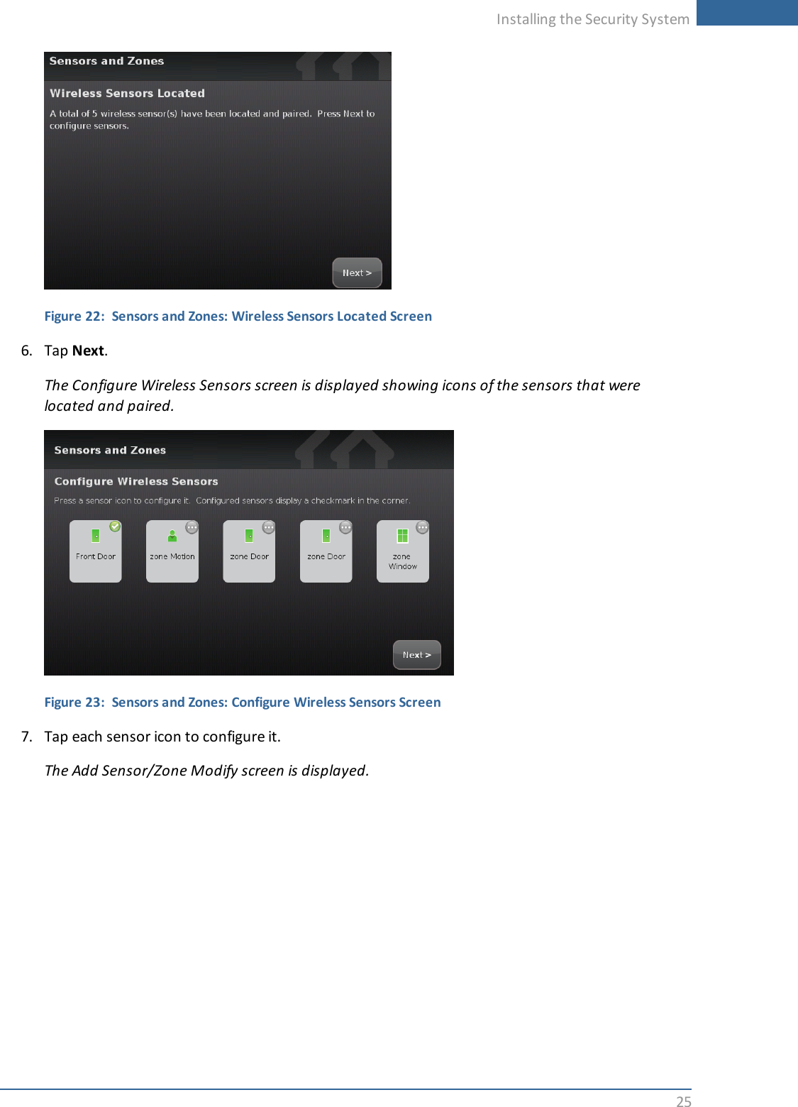
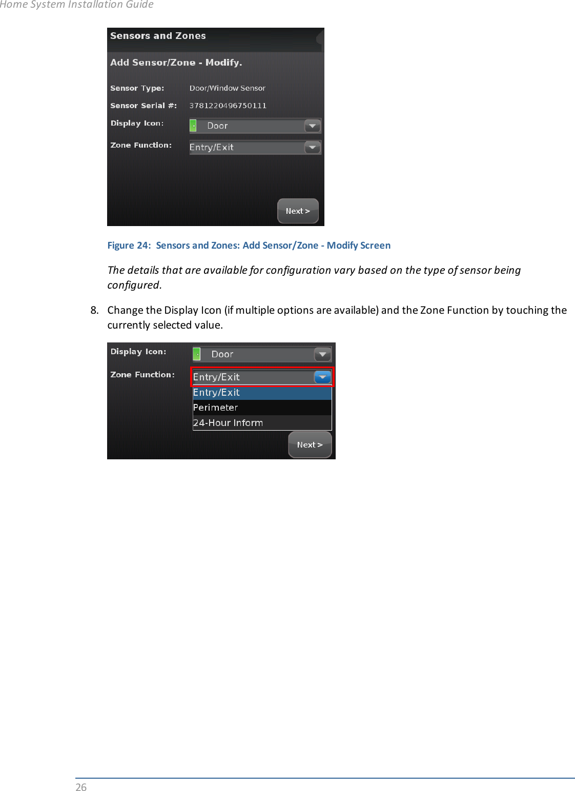
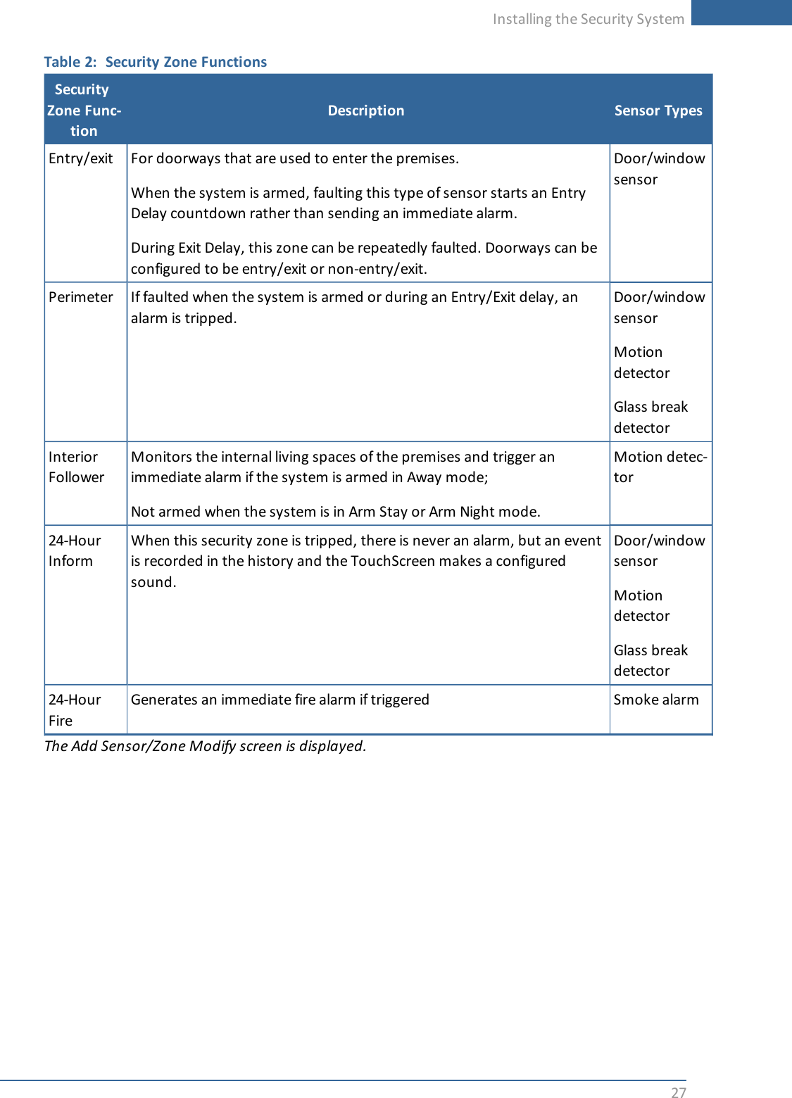
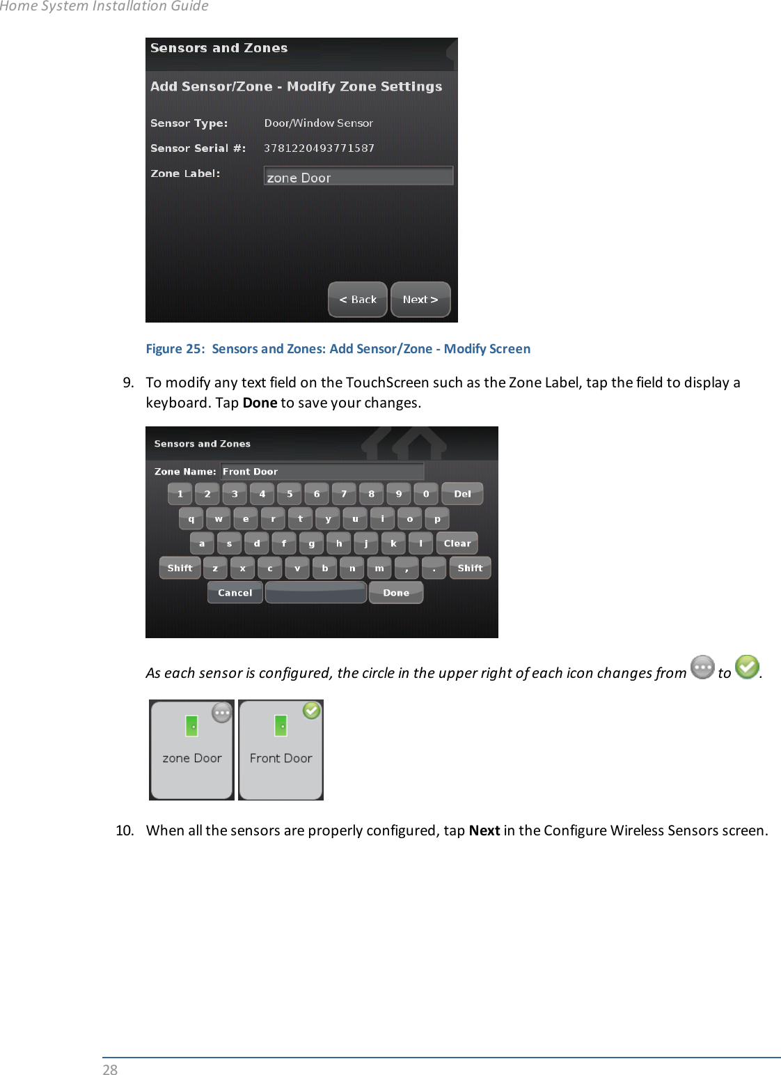
Installation Guide
2.
Quick Start Guide
3.
User Guide
4.
Installation Guide Part 2
5.
Installation Guide 1
6.
Installation Guide 2
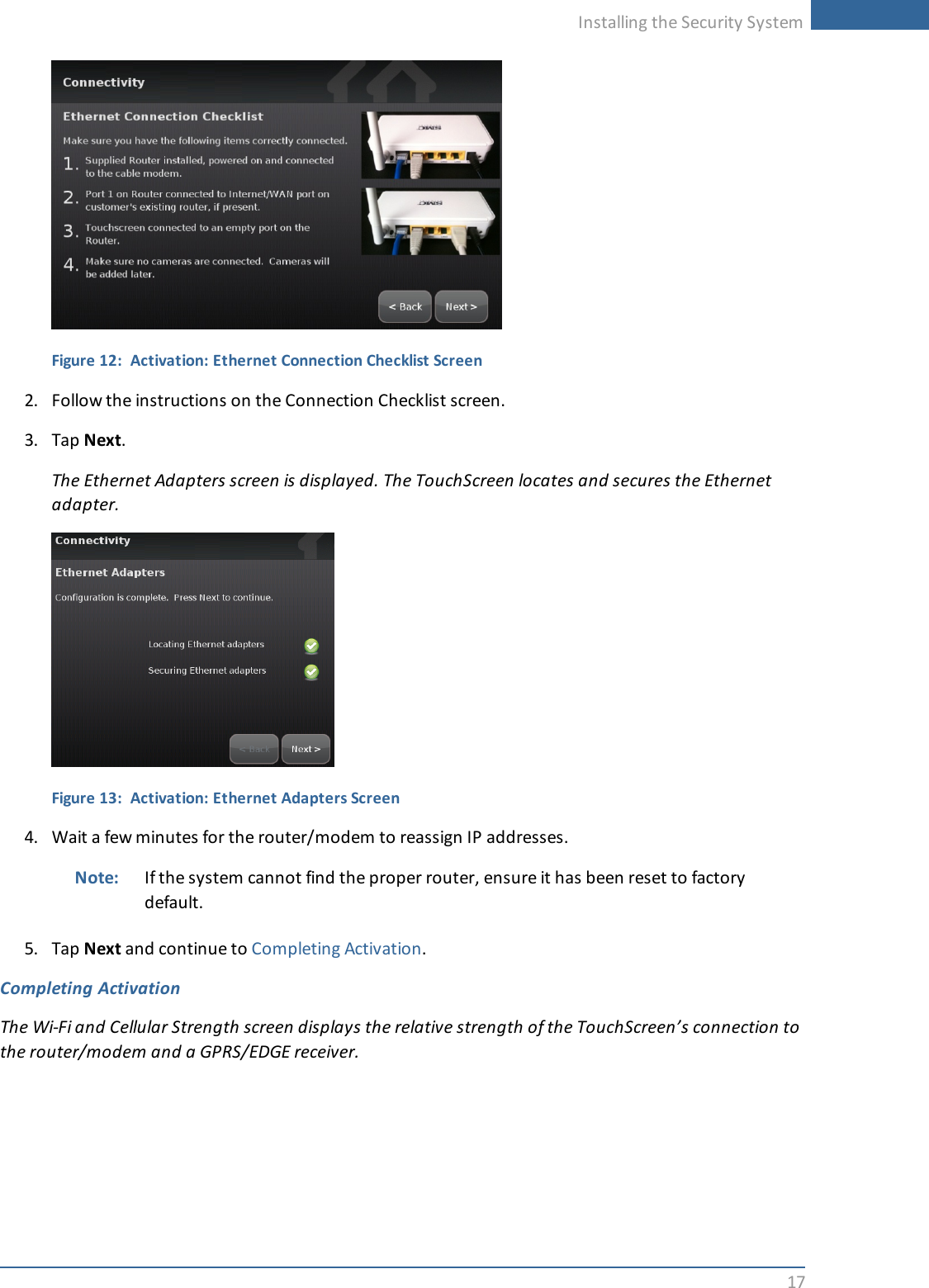
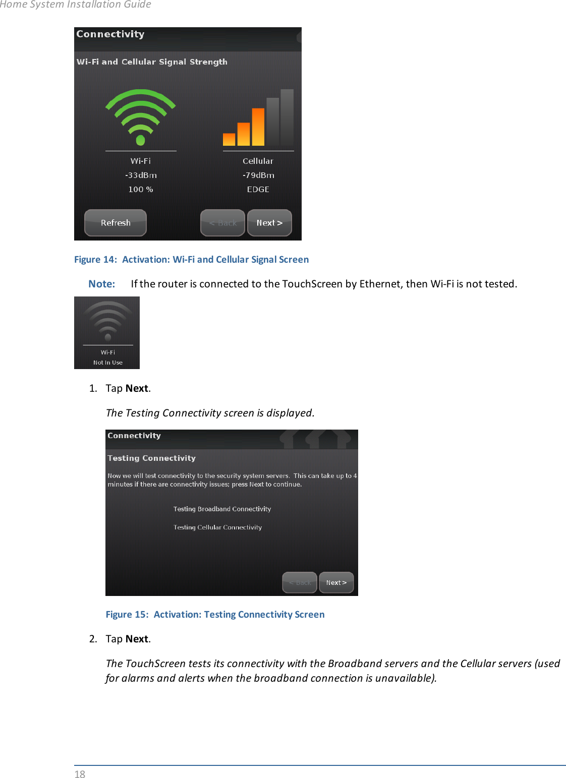
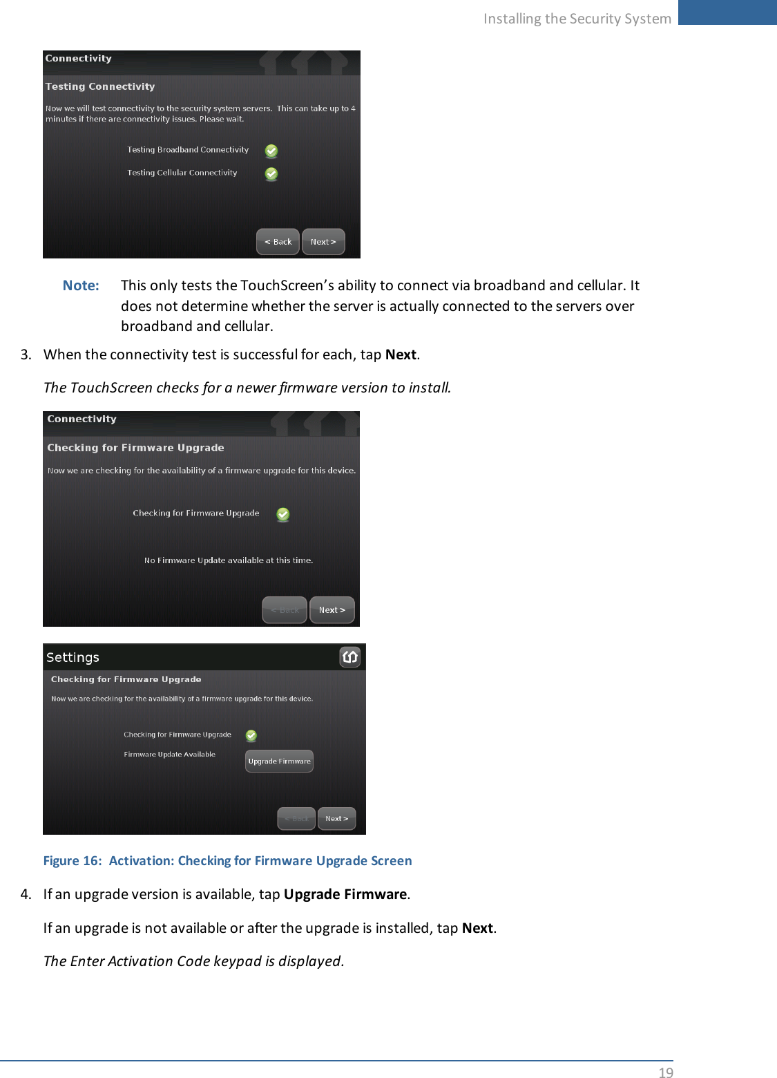
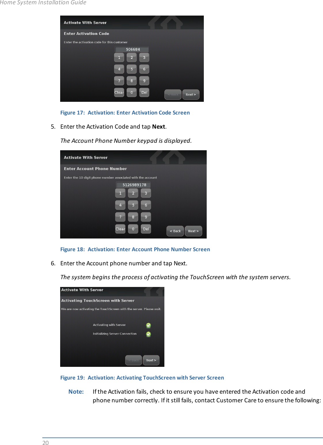
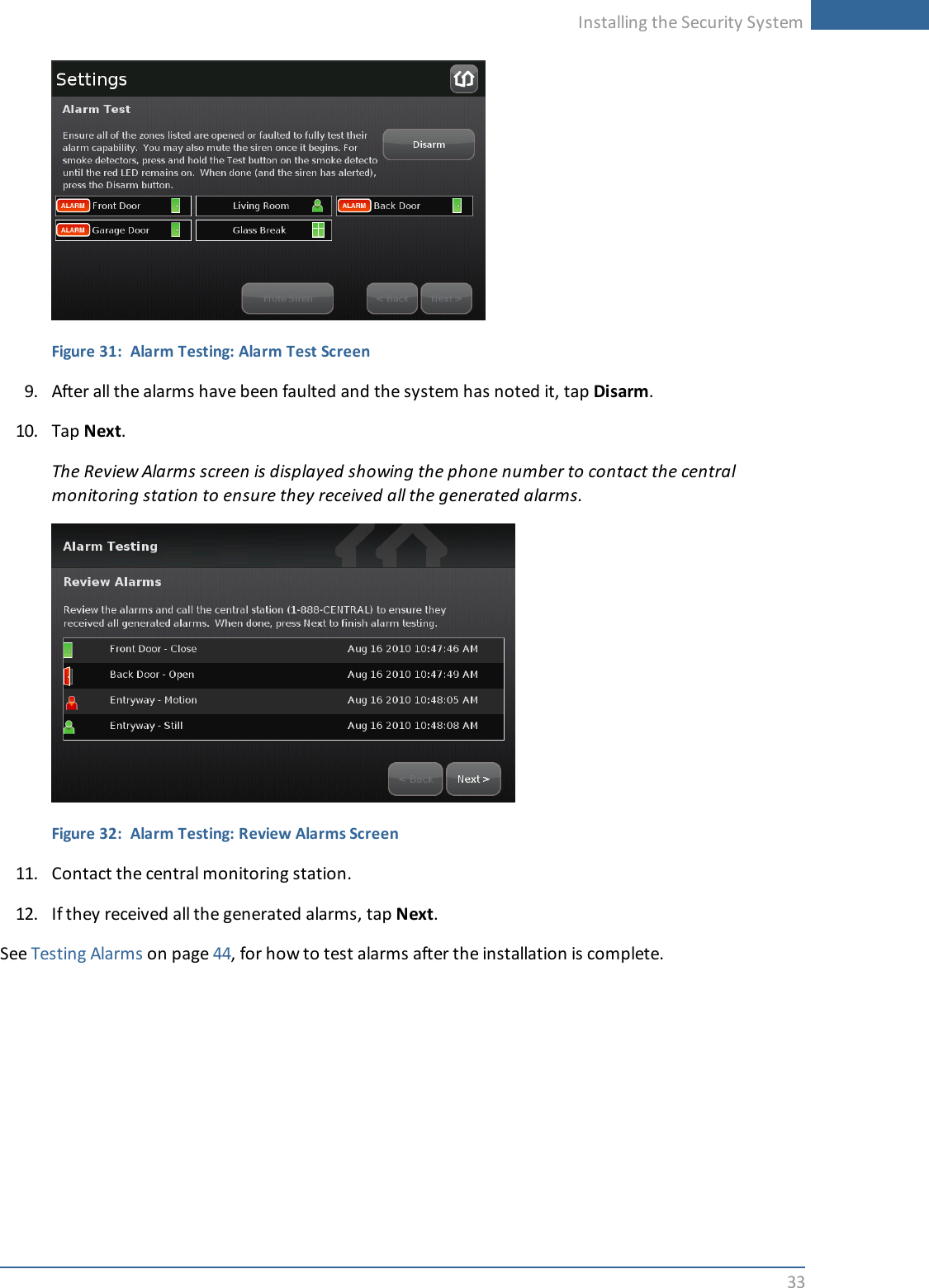
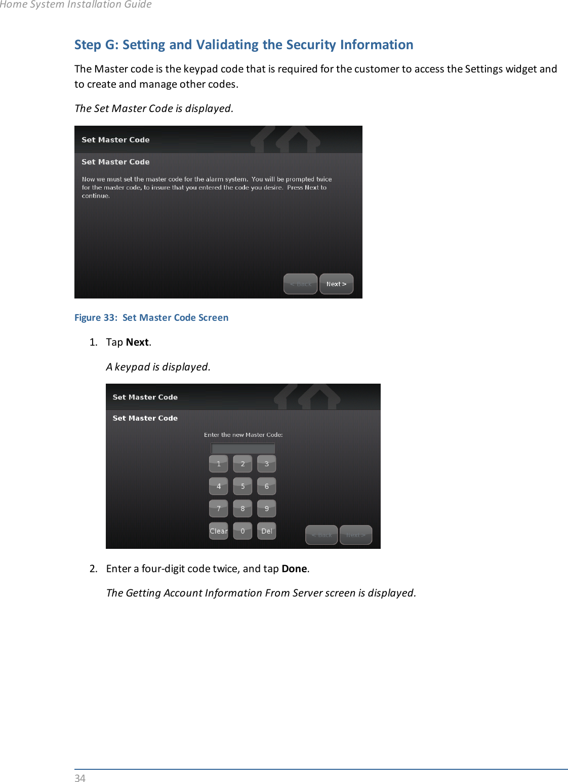
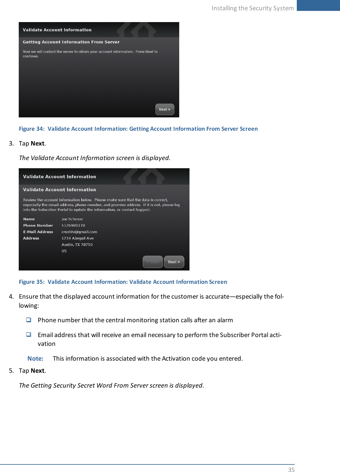
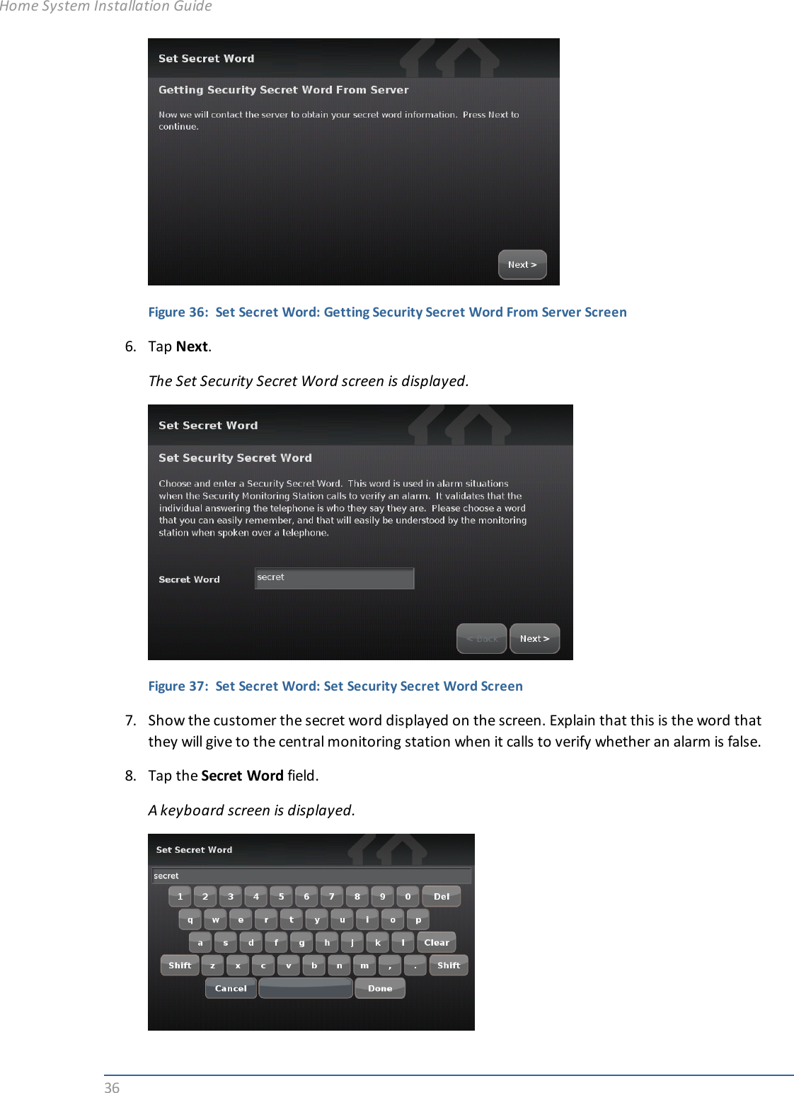
Installation Guide
Navigation menu
Upload a User Manual
Namespaces
Wiki Guide
HTML
PDF
Info
Views
User Manual
Discussion / Help
Navigation