Technicolor Connected Home USA TCA200 Touch Screen Alarm Panel User Manual Home Installation Guide
Technicolor Connected Home USA LLC Touch Screen Alarm Panel Home Installation Guide
Contents
Installation Guide

Home System Installation
Guide
Technicolor TCA200
Release 3.8 Grenada SU1

2
Copyright © 2011 iControl Networks All rights reserved.
No reproduction in whole or in part without prior written approval. iControl Networks, iControl, and
iControl logo design are pending trademarks of iControl Networks. All other trademarks are the property
of their respective owners. Information contained herein is subject to change without notice. The only
warranties for iControl products and services are set forth in the express warranty statements
accompanying such products and services. Nothing herein should be construed as constituting an
additional warranty. iControl Networks shall not be liable for technical or editorial errors or omissions
contained herein. All rights reserved.
Audience
This guide is intended for people who want to use the Subscriber Portal> to access their TouchScreen
settings and monitor their location.
Typographic Conventions
This document uses the following typographic conventions to help you locate and identify information:
Italic text Identifies new terms, emphasis, and book titles
Bold text Identifies button names and other items that you can click or touch in the graphical
user interface or press on a computer keyboard
Note: Notes provide extra information about a topic that is good to know but not essential to the
process.
CAUTION: Cautions draw your attention to actions that could compromise the security of your system
or result in the loss of data.
Home System Installation Guide
Overview
3
Overview
To set up the security system in a customer premises:
1. Complete a Home Security Survey (HSS) for the customer.
2. Ensure the customer premise has access to the Internet.
3. Activate the TouchScreen (see Installing the Security System on page 5).
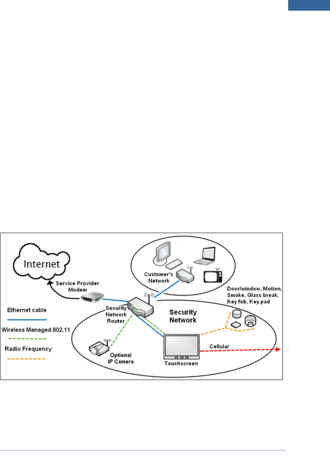
The TouchScreen can connect to the managed router/modem either wirelessly or by Ethernet cable. The
TouchScreen communicates with sensors by radio frequency. Optional cameras communicate with the
security network router wirelessly. The TouchScreen maintains communication with the system servers
through the Internet and by Cellular.
The security network router MUST be installed “in front” of all other home networks relative to the
Internet. Connect the customer’s home network to the Internet through the security network router by
Ethernet cable as described on pages 14 and 16). The customer can install a retail router behind the
security network router and access the Internet. The customer can choose to expose their retail router to
the Internet through the DMZ of the security network router as described in the TouchScreen User
Guide.
A MAXIMUM of six IP cameras and 31 ZigBee devices are supported for the system. ZigBee devices
consist of anything that communicate with the TouchScreen over Radio Frequency, such as
Door/Window sensors and smoke detectors.
Figure 1: Home Security Configuration
4
Installation Tools
The following are the tools required to install the security system:
Digital multi-meter
Rubbing alcohol with container to
dilute with water
Paper towels
Drop cloth for work area
Ladder 6’
Compressed air and soft-bristled
Assorted screwdrivers
Sound sensor tester for testing glass
break sensors
Aerosol smoke tester
Double-sided sticky tape
Alternative double-sided sticky tape
Tape measure
Pocket level
Multi-purpose scissors
Flashlight
Shoe covers
Ethernet cable of sufficient length
(used to configure the camera or
if the TouchScreen will not connect to the
router/modem wirelessly)
Home System Installation Guide

Installing the Security System
5
Installing the Security System
Installing the security system in the customer’s home consists of the following general processes. These
processes are detailed in the following pages of this section:
A. Setting up the Router (page 6)
B. Installing the TouchScreen (page 7)
C. Ensure your TouchScreen Configuration Information is Correct (page 11)
D. Activating the System (page 13)
E. Adding Sensors (page 22)
F. Testing the Alarm Functionality of the Security System (page 30)
G. Setting and Validating the Security Information (page 34)
H. Mounting the Sensors (page 38)
I. Activating the Subscriber Portal (page 38)
J. Configuring the TouchScreen (page 39)

6
Step A: Setting up the Router
1. Ensure the customer premises have access to the Internet.
2. Reset the home network router.
Note: Do this, also, if you are restarting the installation process after having established the
connection between the TouchScreen and the router.
Home System Installation Guide
Installing the Security System
7
Step B: Installing the Technicolor TouchScreen
Note: To mount the TouchScreen on a wall, perform the procedure described on page 79.
1. Remove the TouchScreen from its packaging.
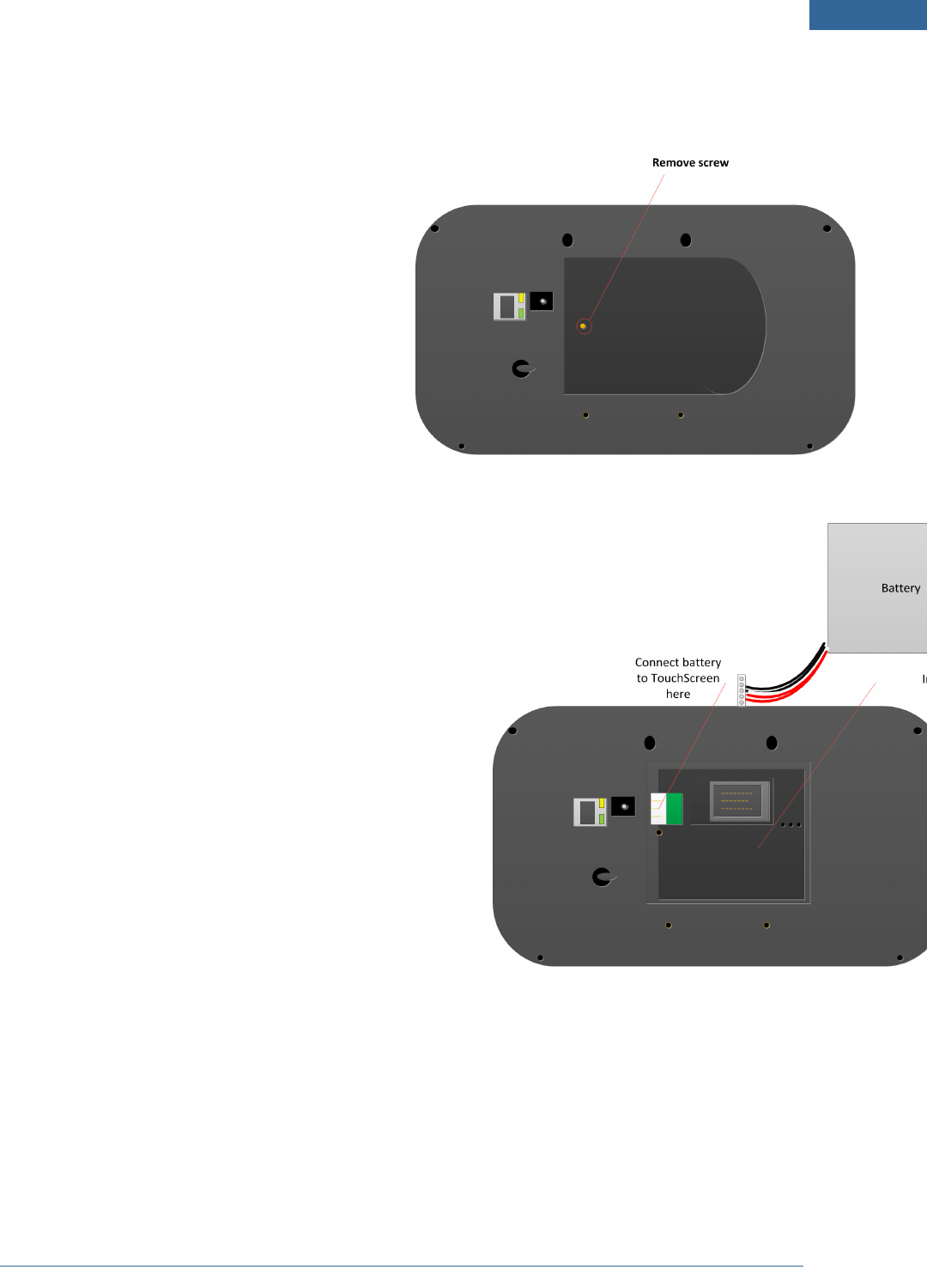
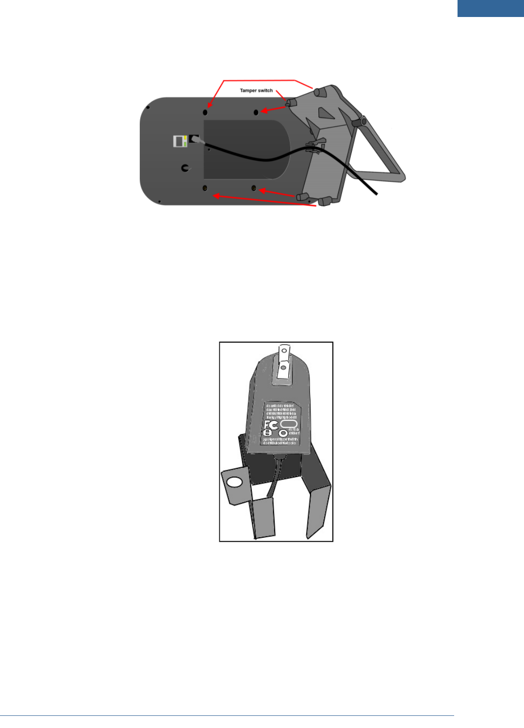
2. Use a P1 Phillips screwdriver to remove the (1)
screw from the battery cover of the Touch-
Screen, and detach the cover.
The 4.0 volt lithium polymer battery is
wrapped and unconnected in the battery
compartment of the TouchScreen.
3. Unwrap the battery from its packaging and install it in the battery compartment.
4. Position the battery and cables inside the battery com-
partment so the cables lie along the top of the battery.
5. Align and connect the battery’s pins to the battery con-
nector so that the wire order is (left-to-right) RED,
WHITE, BLACK.
6. Replace the battery cover and the screw.
7. Place the DC power cable into the clamp of the TouchScreen stand.
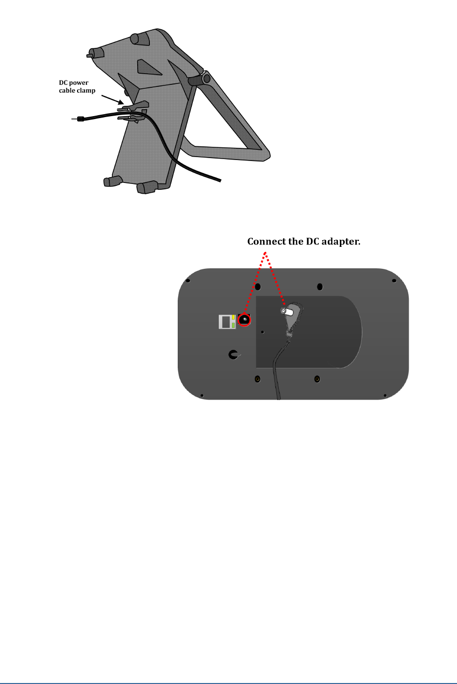
8
8. Connect the DC adapter cable to
the back of the TouchScreen.
9. Connect the stand to the back of the TouchScreen. Insert the longest peg into the Tamper Switch
hole, which is the top right hole on the back of the TouchScreen.
Home System Installation Guide
Installing the Security System
9
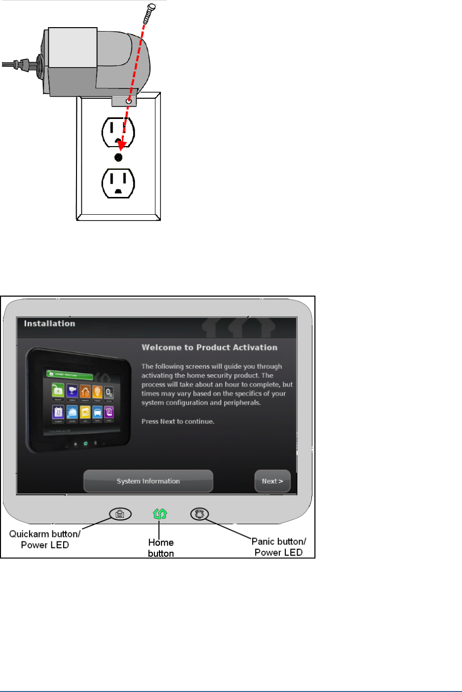
10. Position the TouchScreen near an un-switched wall outlet (not controlled by a light switch).
10. If the installation plan does not involve the TouchScreen connecting to the customer’s network
wirelessly, then connect an Ethernet cable to the TouchScreen and the iControl-dedicated router.
11. Insert the A/C adapter into the bracket as
shown.
Table 1: A/C Power Supply Ratings
Rating Value
Voltage 100 - 240 V
Current 0.5A
Power
Frequency 50/60 Hz
10
12. Remove the center screw from the wall outlet.
13. Plug the TouchScreen’s A/C adapter into the TOP plug of the
wall outlet, and replace the center screw through the bracket
hole.
Note: If the TouchScreen does not display the Installation Welcome screen, you must reset it to
factory default (see page 51).
After a few seconds, the Installation Welcome screen is displayed on the TouchScreen.
Figure 2: Activation: Installation Welcome Screen
Note: If the TouchScreen does not display the Installation Welcome screen, you must reset it to
factory default (see page 51).
Home System Installation Guide
Installing the Security System
11
Step C: Ensure Your TouchScreen Configuration Information Is Correct
1. Ensure you have the following information from Customer Care:
Activation Code
Broadband Server IP
Cellular Server IP
Cellular APN
Deployment to which the TouchScreen, based on CPE ID, is applied in Inventory
(only if your system uses deployments).
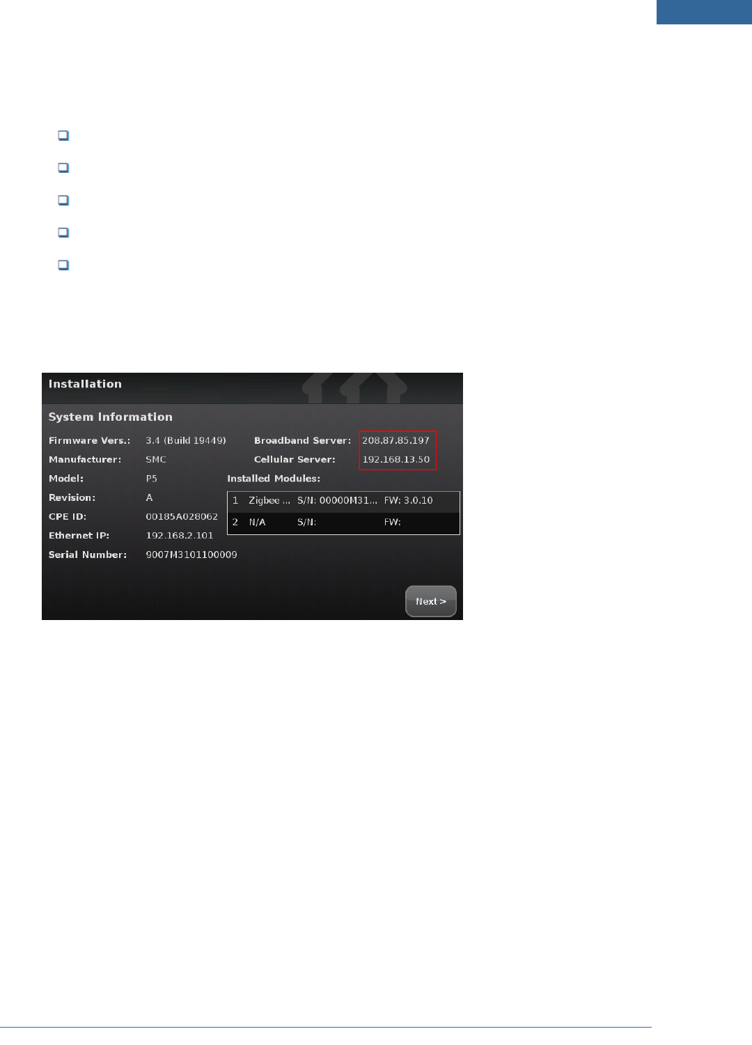
2. On the TouchScreen, tap System Information.
The System Information screen is displayed.
Figure 3: Activation: System Information Screen
3. Tap directly on the Broadband Server value (the IP).
The Edit System Configuration Information screen is displayed.
4. Tap the Broadband Server IP, Cellular Server IP, and the Cellular APN value to change them. When
you tap them, a keyboard screen is displayed. Enter the new values and tap Done.
5. After all the values have been set, tap Next.
The System Information screen is displayed.
6. Tap Next.
The Welcome screen is displayed.
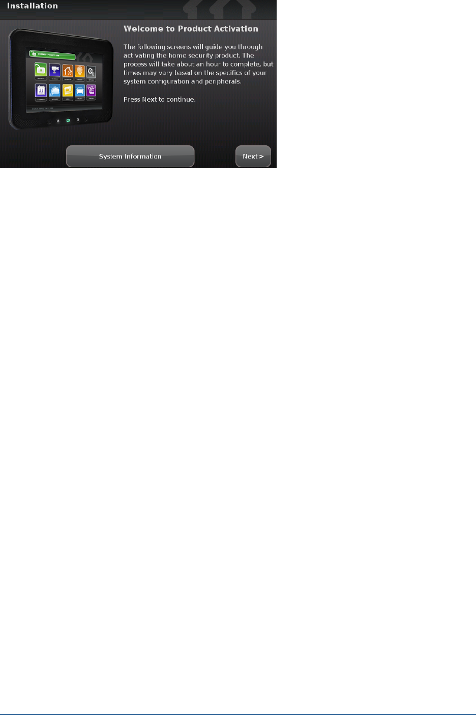
12
Figure 4: Welcome to Product Activation Screen
Home System Installation Guide
Installing the Security System
13
Step D: Activating the System
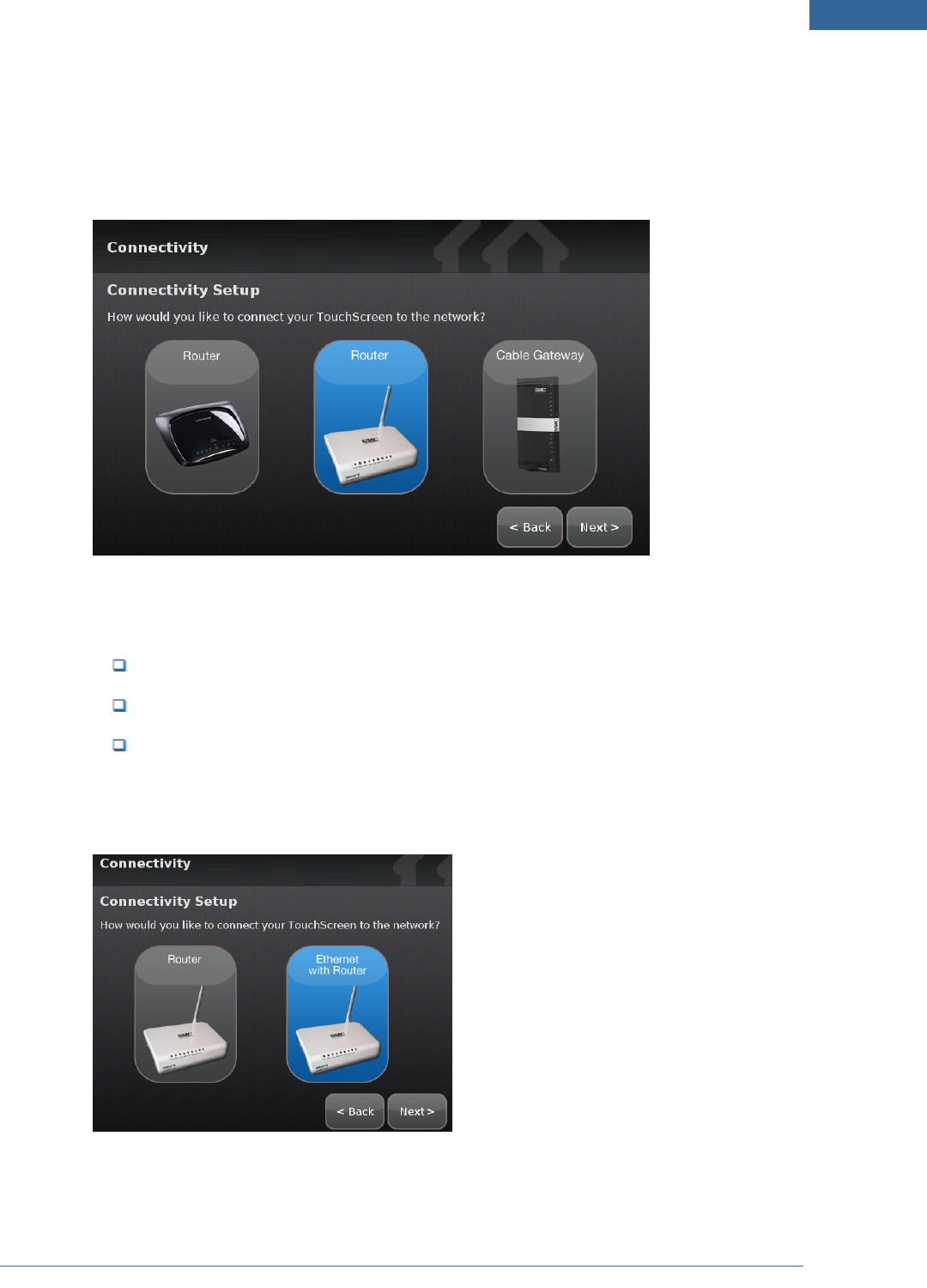
1. Tap Next.
The Connectivity Setup screen displays the type of Internet routers to which the
TouchScreen will connect.
Figure 5: Activation: Connectivity Setup Screen
The activation process now supports the following routers:
DOCSIS 2.x 8014-WN
SMC WBR14S-N4
Netgear WNR1000v1, WNR1000v2
2. Tap the type of router the TouchScreen will connect to, and tap Next.
The Connectivity Setup screen displays options for connecting to the router/modem.
The following options are displayed:
14
Router - TouchScreen connects to the router/modem wirelessly. If you select this
option, follow the procedures described in For Wireless TouchScreen-to-Router Con-
nectivity.
Ethernet with Router TouchScreen connects to the router/modem using an
Ethernet cable. If you select this option, following the procedures described in For
Cabled TouchScreen-to-Router Connectivity.
For Wireless TouchScreen-to-Router Connectivity
Figure 6: Activation: Initial Router Configuration, Wireless Router-to-TouchScreen
1. Tap Router and then tap Next.
The Router Connection Checklist is displayed.
Figure 7: Activation: Router Connection Checklist Screen
2. Follow the instructions on the Connection Checklist screen.
Home System Installation Guide
Installing the Security System
15
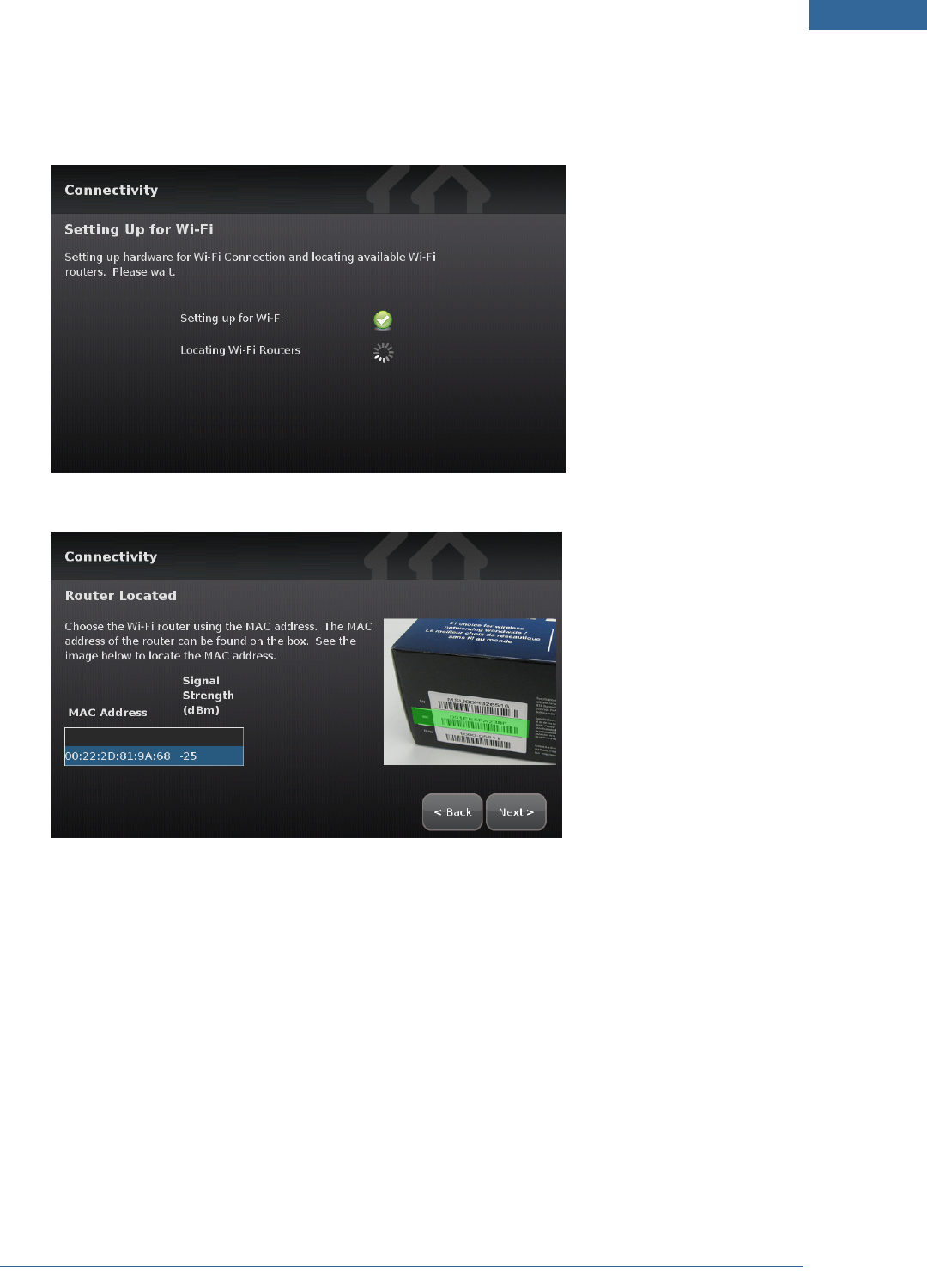
3. Tap Next.
The TouchScreen locates all the available wireless routers in range, and displays their MAC
address.
Figure 8: Activation: Setting Up for Wi-Fi Screen
Figure 9: Activation: Router Located Screen
4. Check the MAC address for the router/modem to which the TouchScreen must connect (usually
located at the back of the device).
5. Tap the MAC address for the correct router.
6. Tap Next.
The Configuring and Securing the Router screen is displayed as the TouchScreen establishes a
firm connection with the router/modem, the Broadband servers, and the Cellular connectivity
servers.
16
Figure 10: Activation: Configuring and Securing Router Screen
Continue to "Completing Activation" on page 17
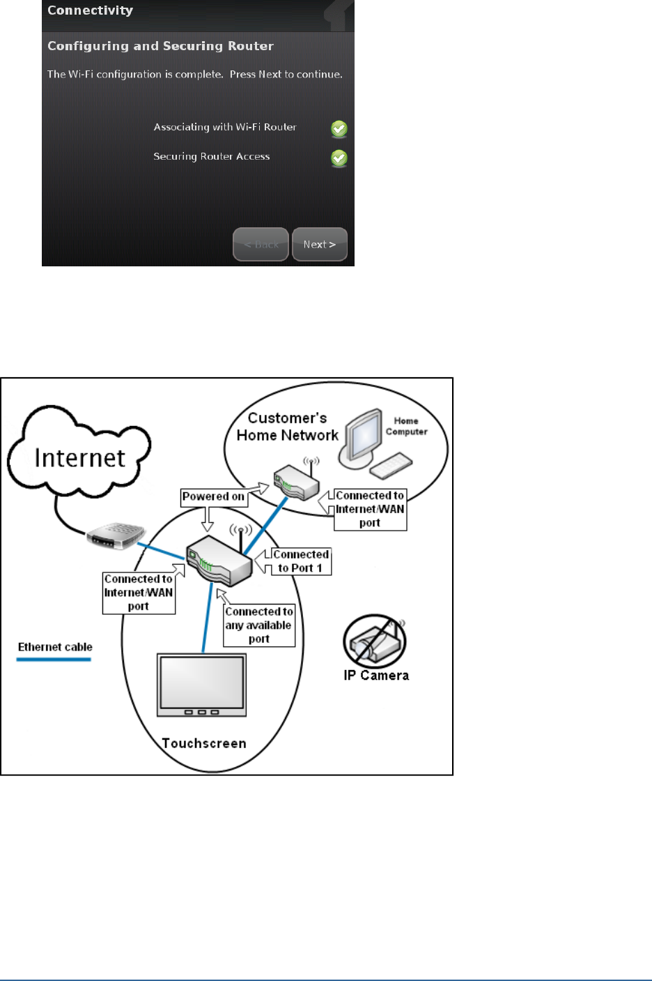
For Cabled TouchScreen-to-Router Connectivity
Figure 11: Activation: Initial Router Configuration, Ethernet Router-to-TouchScreen
1. Tap Ethernet with Router and then tap Next.
The Ethernet Connection Checklist is displayed.
Home System Installation Guide
Installing the Security System
17
Figure 12: Activation: Ethernet Connection Checklist Screen
2. Follow the instructions on the Connection Checklist screen.
3. Tap Next.
The Ethernet Adapters screen is displayed. The TouchScreen locates and secures the Ethernet
adapter.
Figure 13: Activation: Ethernet Adapters Screen
4. Wait a few minutes for the router/modem to reassign IP addresses.
Note: If the system cannot find the proper router, ensure it has been reset to factory
default.
5. Tap Next and continue to Completing Activation.
Completing Activation
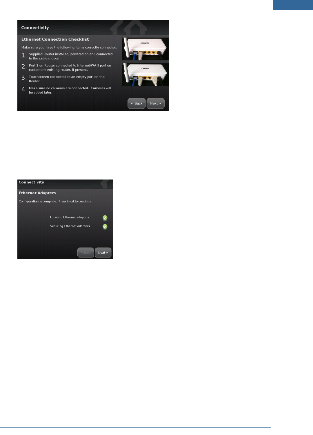
The Wi-Fi and Cellular Strength screen displays the relative strength of the TouchScreen’s connection to
the router/modem and a GPRS/EDGE receiver.
18
Figure 14: Activation: Wi-Fi and Cellular Signal Screen
Note: If the router is connected to the TouchScreen by Ethernet, then Wi-Fi is not tested.
1. Tap Next.
The Testing Connectivity screen is displayed.
Figure 15: Activation: Testing Connectivity Screen
2. Tap Next.
The TouchScreen tests its connectivity with the Broadband servers and the Cellular servers (used
for alarms and alerts when the broadband connection is unavailable).
Home System Installation Guide
Installing the Security System
19
Note: This only tests the TouchScreen’s ability to connect via broadband and cellular. It
does not determine whether the server is actually connected to the servers over
broadband and cellular.
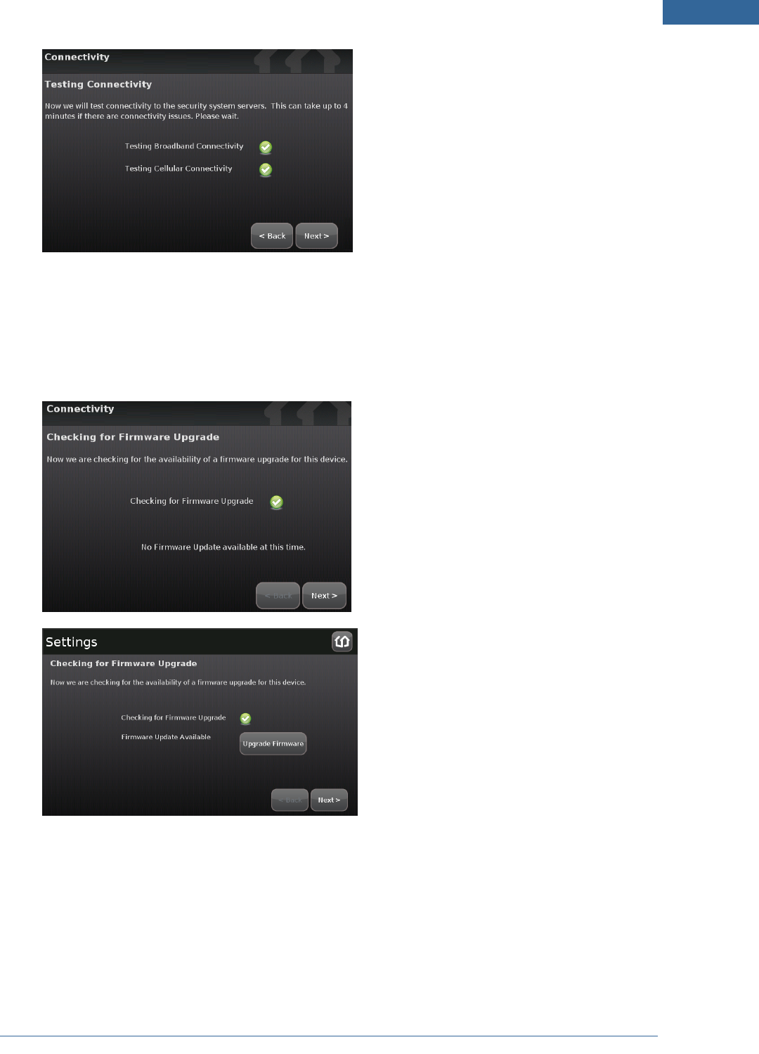
3. When the connectivity test is successful for each, tap Next.
The TouchScreen checks for a newer firmware version to install.
Figure 16: Activation: Checking for Firmware Upgrade Screen
4. If an upgrade version is available, tap Upgrade Firmware.
If an upgrade is not available or after the upgrade is installed, tap Next.
The Enter Activation Code keypad is displayed.
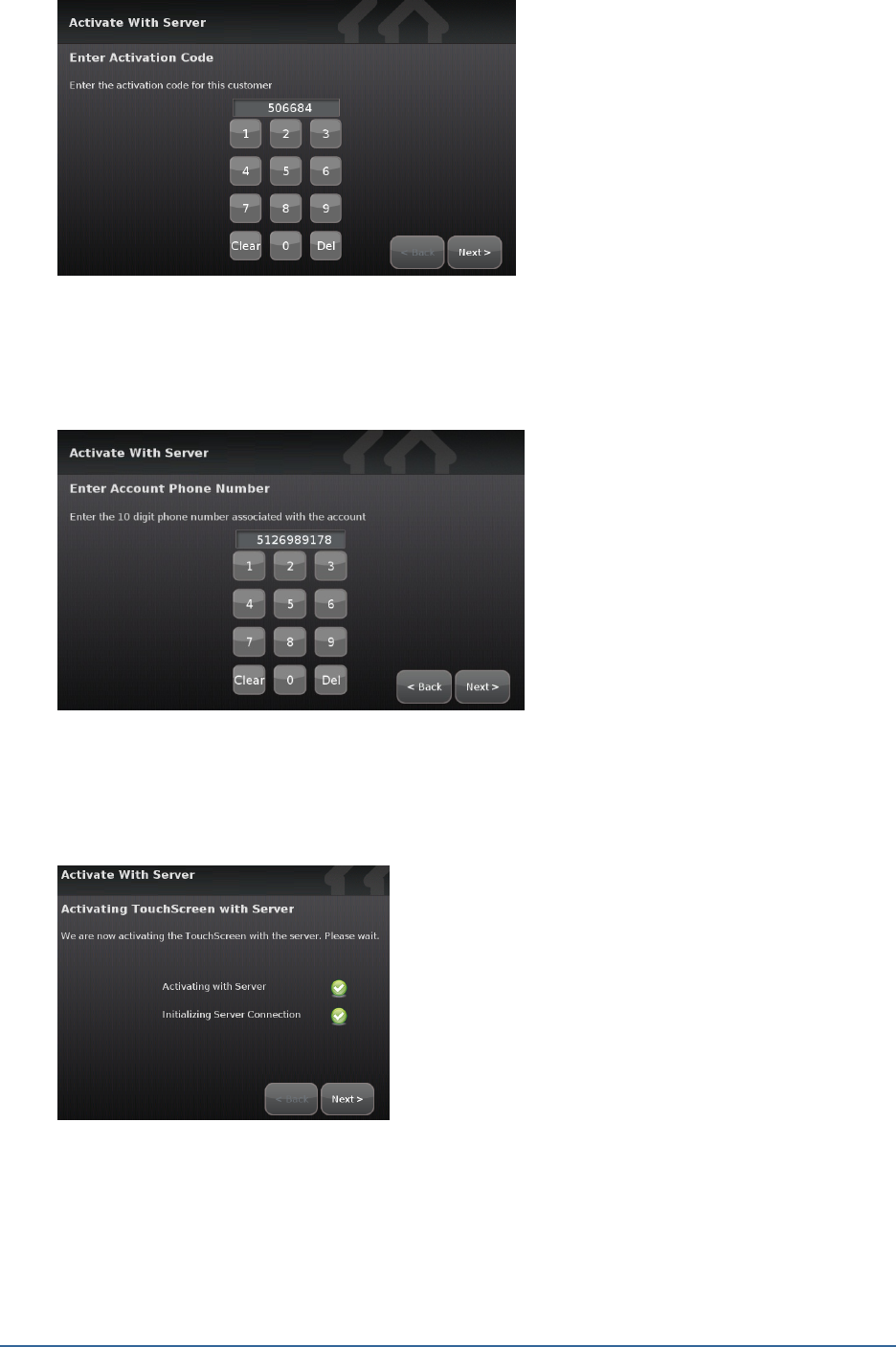
20
Figure 17: Activation: Enter Activation Code Screen
5. Enter the Activation Code and tap Next.
The Account Phone Number keypad is displayed.
Figure 18: Activation: Enter Account Phone Number Screen
6. Enter the Account phone number and tap Next.
The system begins the process of activating the TouchScreen with the system servers.
Figure 19: Activation: Activating TouchScreen with Server Screen
Note: If the Activation fails, check to ensure you have entered the Activation code and
phone number correctly. If it still fails, contact Customer Care to ensure the following:
Home System Installation Guide
Installing the Security System
21
Activation information is correct.
Customer’s account is ready for Activation.
Customer’s account is paired with another TouchScreen device.
TouchScreen device is not paired with another account (RMA device).
TouchScreen is added to inventory.
TouchScreen CPE ID is assigned to the same deployment as the customer account.
7. When the server activation process is completed, tap Next.
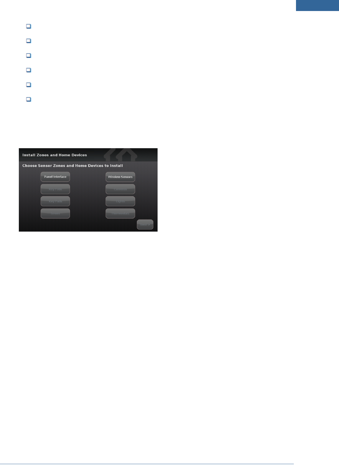
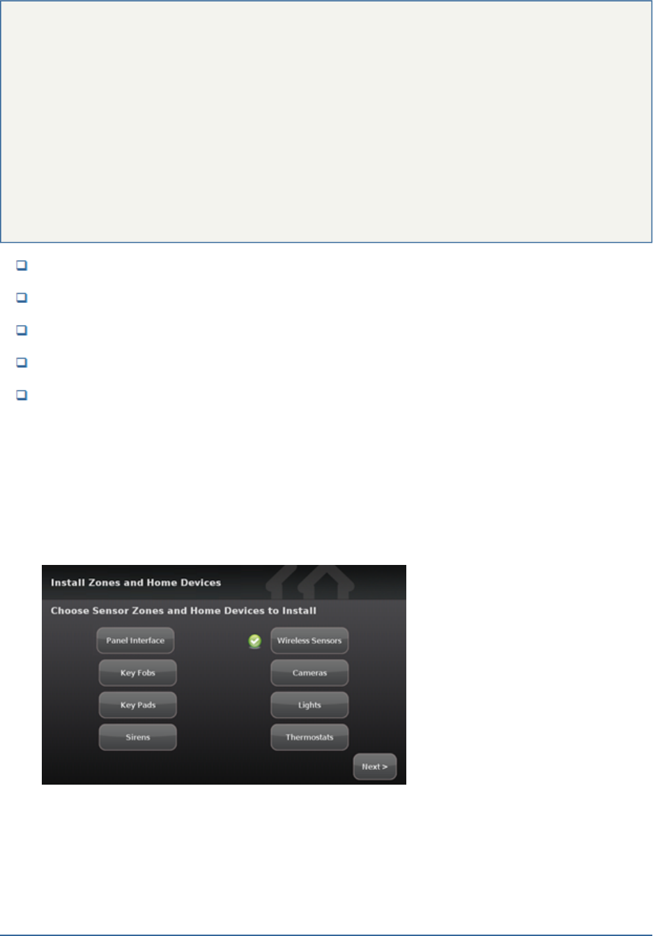
A screen is displayed offering options to pair the TouchScreen various security and
environmental devices. You must connect your wireless sensors first.
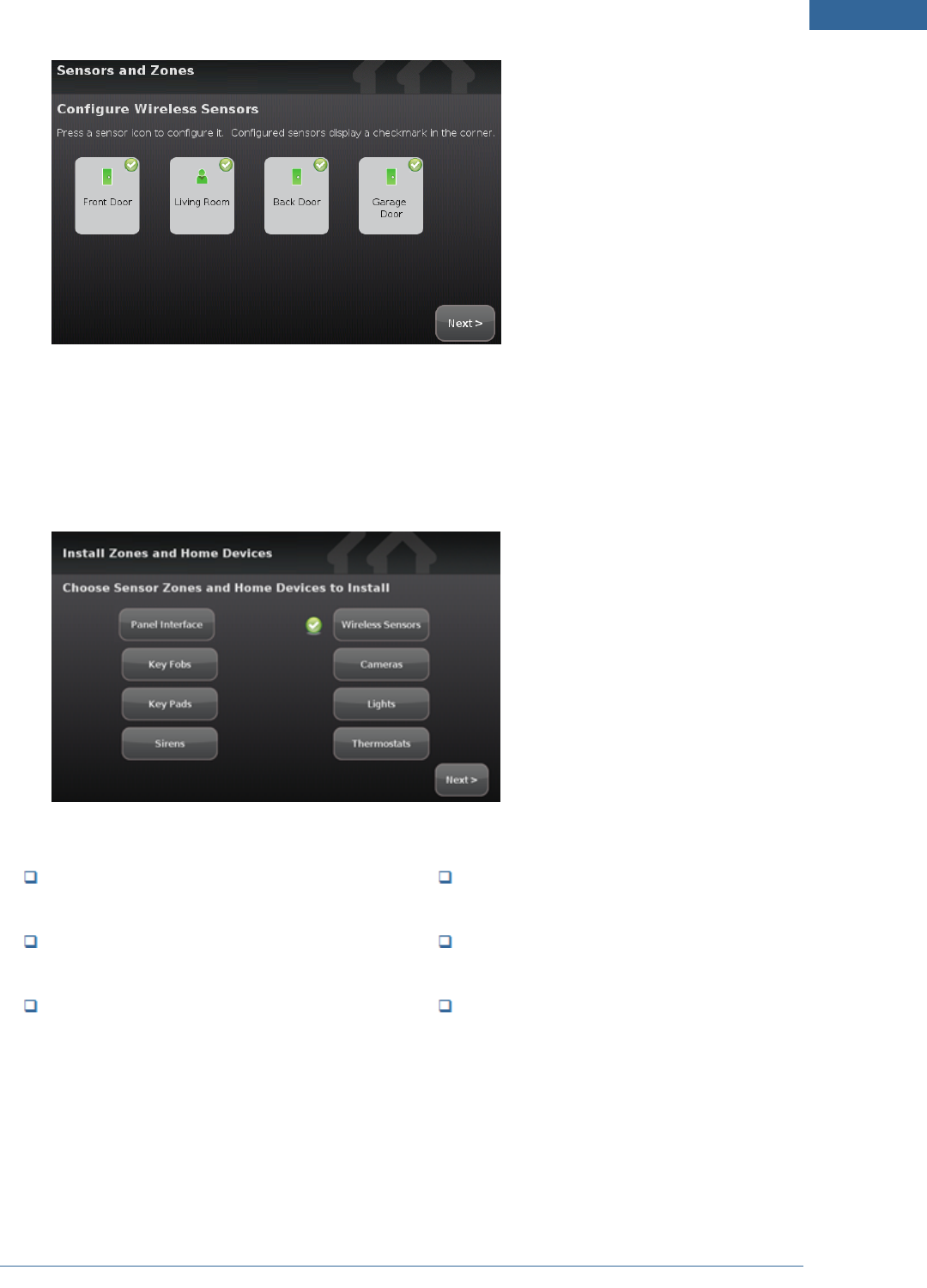
Figure 20: Install Zones and Home Devices Screen
Note: To test the security connectivity the Internet and cellular servers (after activation):
From the Settings widget, tap Advancead Settings ®Connectivity ®Test Connectivity.
The Wi-Fi and Cellular Signal Strength screen is displayed.
22
Step E: Adding Sensors to the Security System
A MAXIMUM of six IP cameras and 31 ZigBee devices are supported for the system. Zig-
Bee devices consist of anything that communicate with the TouchScreen over Radio
Frequency, such as Door/Window sensors and smoke detectors.
Once a sensor or peripheral has been paired to a TouchScreen, it MUST be deleted from
that TouchScreen before it can be paired to a different TouchScreen. When a sensor is
deleted from a TouchScreen, it is automatically reset to factory defaults and is placed in
Search mode, ready to be paired with another TouchScreen. It is possible to pair a
device to a second TouchScreen without deleting it from the original, but this could
result in the paired device not being registered in the server databases. This situation is
most often encountered in lab environments where Touchscreens and
sensors/peripherals are often swapped back and forth on a regular basis.
Sensors are devices that do one of the following:
Monitor the opening and closing of doors and windows
Detect motion
Monitor the nearby sound of breaking glass
Detect smoke and heat
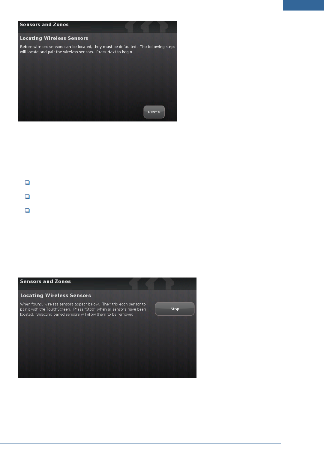
IMPORTANT: If you need to update the firmware on any sensor before adding it to the security
system, you must reset the sensor to factory defaults before adding it to the
OpenHome Converge system. This is essential so that it can receive the necessary
changes to communicate with the TouchScreen.
Note: This step can be performed after Activation.
1. Tap Wireless Sensors.
The Locating Wireless Sensors screen is displayed.
Home System Installation Guide
Installing the Security System
23
Figure 21: Sensors and Zones: Locating Wireless Sensors Screen
See the installation documentation for each of your sensor device types to prepare them to be
added to the TouchScreen and to place them in Search mode.
Available sensors meet the following requirements:
Defaulted
Not currently paired with another TouchScreen device
Currently in Search mode
Note: See the sensor installation documentation for how to tell if a sensor is in Search mode,
how to tell if it is not in Search mode, and how to restart Search mode if it is not.
2. Tap Next.
A Stop button is displayed on the Locating Wireless Sensors screen. The TouchScreen searches for
sensors that are available to be added.
As sensors are found, a grayed icon is displayed for that sensor.
24
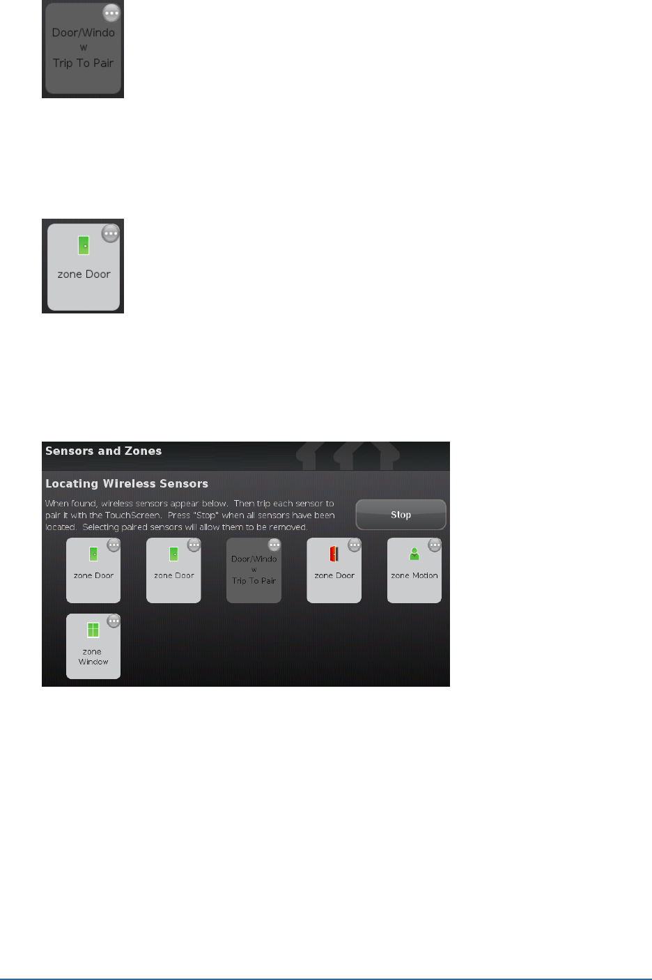
3. Fault each found sensor to pair it to the TouchScreen. For example, for door/window sensors, sep-
arate the magnet and reed switch.
The icon for each sensor is undarkened as it is faulted and the TouchScreen beeps. The sensor is
paired to the TouchScreen.
4. Determine that all the sensors have been located by the TouchScreen.
5. When all the sensors are found and paired, tap Stop.
Note: Any located sensors that were not paired are released by the TouchScreen. Sensors
can be added later (see page 59).
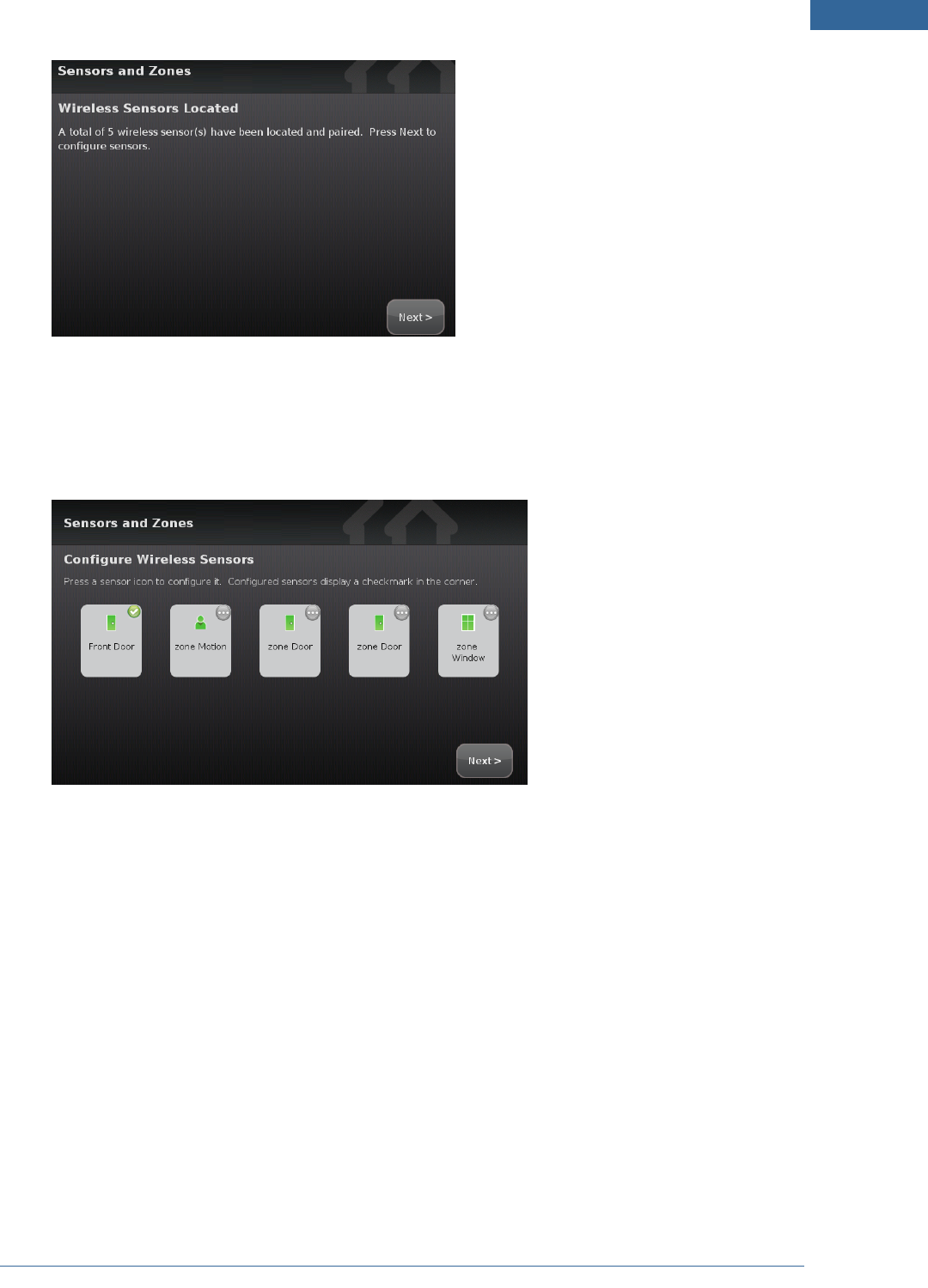
The Wireless Sensors Located screen notes the number of wireless sensors found and paired.
Home System Installation Guide
Installing the Security System
25
Figure 22: Sensors and Zones: Wireless Sensors Located Screen
6. Tap Next.
The Configure Wireless Sensors screen is displayed showing icons of the sensors that were
located and paired.
Figure 23: Sensors and Zones: Configure Wireless Sensors Screen
7. Tap each sensor icon to configure it.
The Add Sensor/Zone Modify screen is displayed.
26
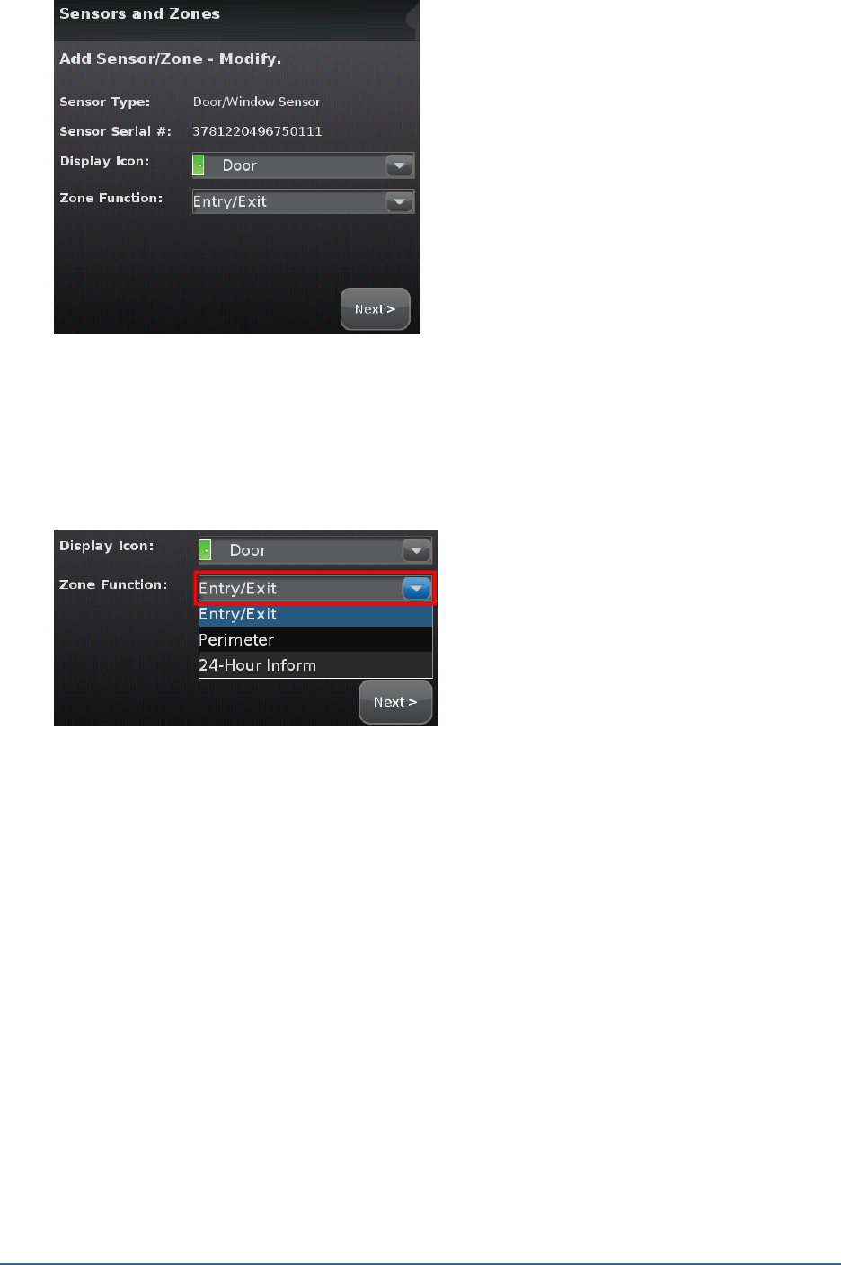
Figure 24: Sensors and Zones: Add Sensor/Zone - Modify Screen
The details that are available for configuration vary based on the type of sensor being
configured.
8. Change the Display Icon (if multiple options are available) and the Zone Function by touching the
currently selected value.
Home System Installation Guide
Installing the Security System
27
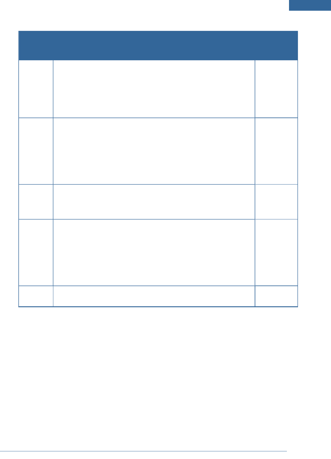
Table 2: Security Zone Functions
Security
Zone Func-
tion
Description Sensor Types
Entry/exit For doorways that are used to enter the premises.
When the system is armed, faulting this type of sensor starts an Entry
Delay countdown rather than sending an immediate alarm.
During Exit Delay, this zone can be repeatedly faulted. Doorways can be
configured to be entry/exit or non-entry/exit.
Door/window
sensor
Perimeter If faulted when the system is armed or during an Entry/Exit delay, an
alarm is tripped.
Door/window
sensor
Motion
detector
Glass break
detector
Interior
Follower
Monitors the internal living spaces of the premises and trigger an
immediate alarm if the system is armed in Away mode;
Not armed when the system is in Arm Stay or Arm Night mode.
Motion detec-
tor
24-Hour
Inform
When this security zone is tripped, there is never an alarm, but an event
is recorded in the history and the TouchScreen makes a configured
sound.
Door/window
sensor
Motion
detector
Glass break
detector
24-Hour
Fire
Generates an immediate fire alarm if triggered Smoke alarm
The Add Sensor/Zone Modify screen is displayed.
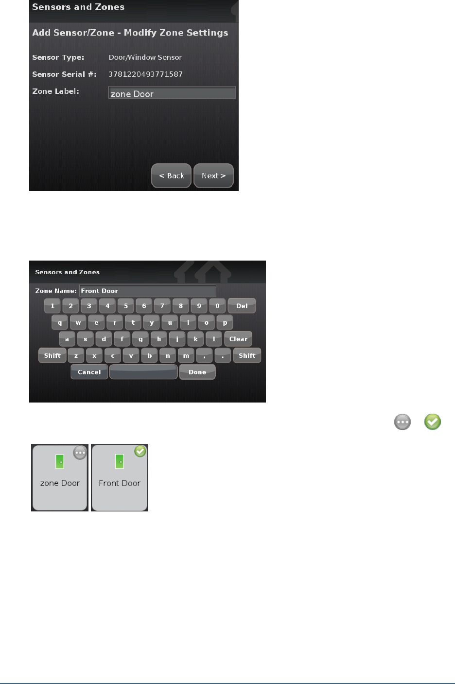
28
Figure 25: Sensors and Zones: Add Sensor/Zone - Modify Screen
9. To modify any text field on the TouchScreen such as the Zone Label, tap the field to display a
keyboard. Tap Done to save your changes.
As each sensor is configured, the circle in the upper right of each icon changes from to .
10. When all the sensors are properly configured, tap Next in the Configure Wireless Sensors screen.
Home System Installation Guide
Installing the Security System
29
Figure 26: Sensors & Zones: Configure Wireless Sensors Screen
11. If all of the sensors have not been configured, the TouchScreen displays the Modify screens for
each sensor to allow you to review its details. Modify the details as needed or tap Next to cycle
through all the sensors.
The wireless sensors are marked as configured.
12. From this point you can configure any or all of the following devices:
Panel Interfaces (see Step A: Adding Panel
Interfaces to the Security System on page 1)
Cameras (see Step A: Adding Cameras to the
Security System on page 1)
Lights (see Step A: Adding Lighting Devices to
the Security System on page 1)
Thermostats (see Step A: Adding a Ther-
mostat to the Security System on page 1)
Key Fobs (see Step A: Adding Key Fobs to
the Security System on page 1)
Key Pads (see Step A: Adding Key Pads to
the Security System on page 1)
After all the devices are configured—or if you want to configure the devices later—tap Next to go to Step
F: Testing the Alarm Functionality of the Security System on next page.
30
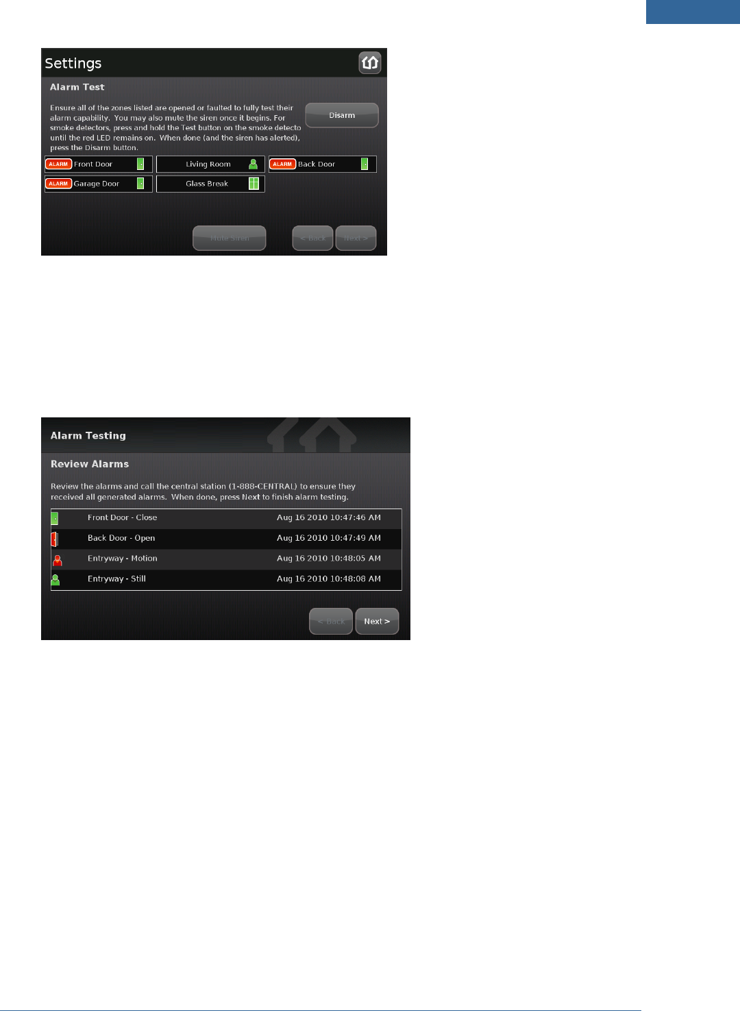
Step F: Testing the Alarm Functionality of the Security System
The Test Alarm screen is displayed.
Figure 27: Alarm Testing: Test Alarm Screen
This step sends a test alarm—through the system servers—to the central monitoring station as though a
genuine alarm had been tripped.
1. Tap Test Alarm.
The TouchScreen informs you that the signal was sent to the central monitoring station. In the
event reports on the Management Portal Account Information screen (History tab and Alarms
tab), this event is reported as “alarm test mode”.
2. After the test alarm has been sent, tap Next.
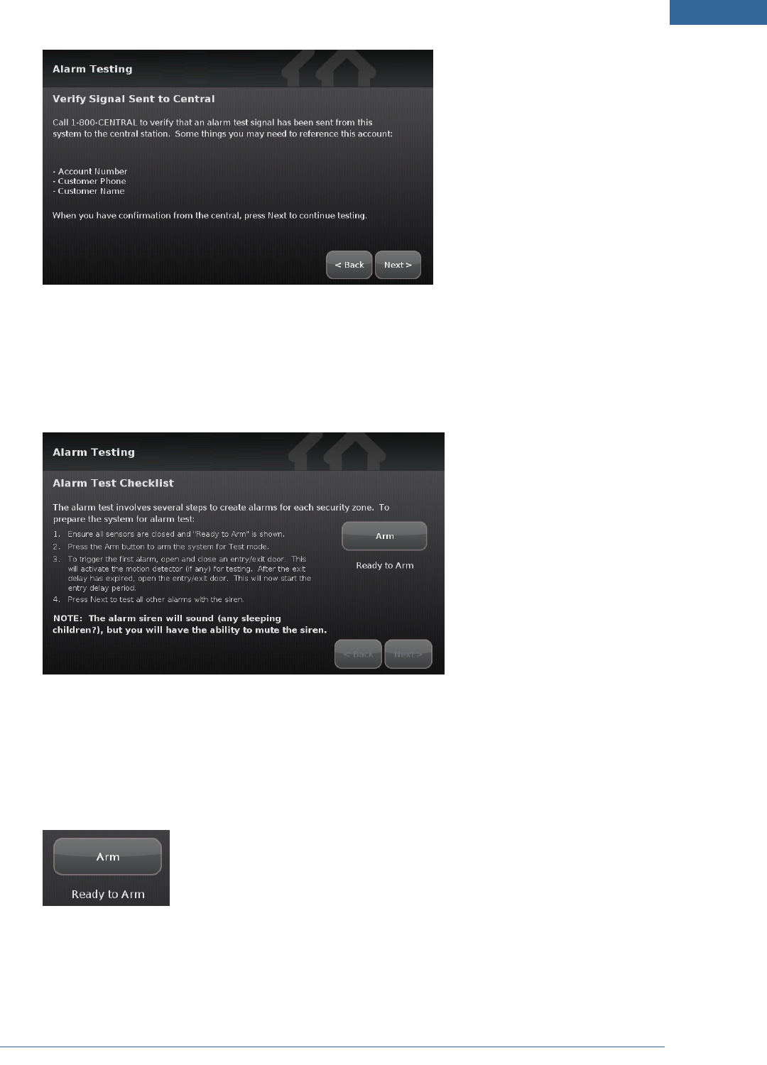
The Verify Signal Sent to Central screen is displayed providing a phone number to the central
monitoring station and the confirmation information of the current customer account.
Home System Installation Guide
Installing the Security System
31
Figure 28: Alarm Testing: Verify Signal Sent to Central Screen
3. Call the provided phone number and give the confirmation information to the representative.
4. When you have confirmed that the test alarm was sent successfully, tap Next.
The Alarm Test Checklist is displayed.
Figure 29: Alarm Testing: Alarm Test Checklist Screen
5. Ensure all the security zones are unfaulted (that is, doors and windows closed, motion detectors
not showing motion, etc.)
When the security zones are ready for testing, “Ready to Arm” is displayed under the Arm
button.
6. Tap Arm.
The after a 10 second Exit Delay period, the button changes to the label System Armed.
32
7. Tap Next.
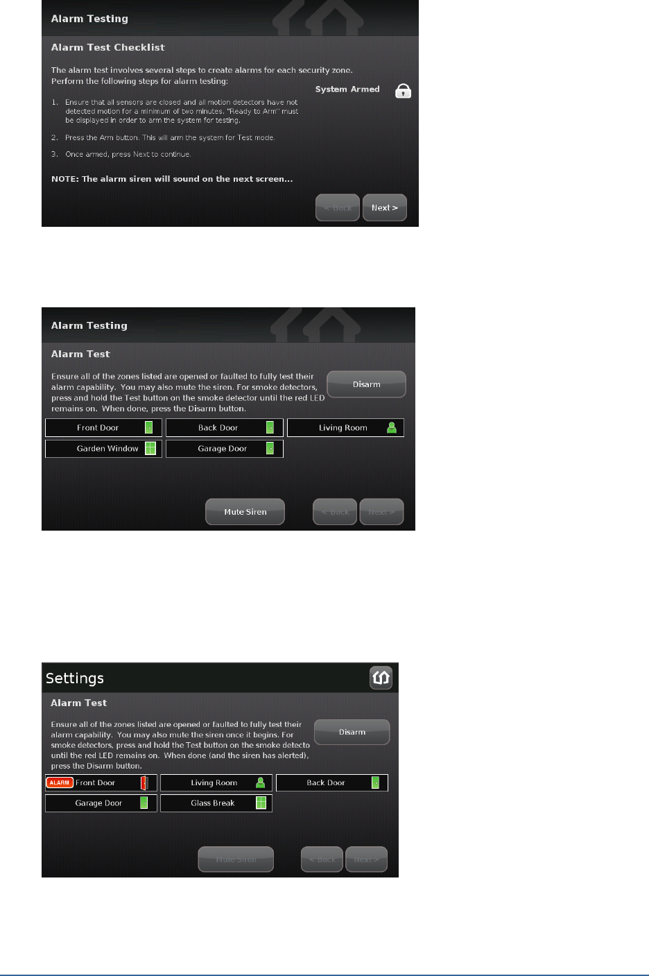
The Alarm Test screen is displayed.
Figure 30: Alarm Testing: Alarm Test Checklist Screen
8. Fault each alarm in turn.
The TouchScreen notes that each sensor communicated an event to the TouchScreen and
initiated an alarm.
Home System Installation Guide
Installing the Security System
33
Figure 31: Alarm Testing: Alarm Test Screen
9. After all the alarms have been faulted and the system has noted it, tap Disarm.
10. Tap Next.
The Review Alarms screen is displayed showing the phone number to contact the central
monitoring station to ensure they received all the generated alarms.
Figure 32: Alarm Testing: Review Alarms Screen
11. Contact the central monitoring station.
12. If they received all the generated alarms, tap Next.
See Testing Alarms on page 44, for how to test alarms after the installation is complete.

34
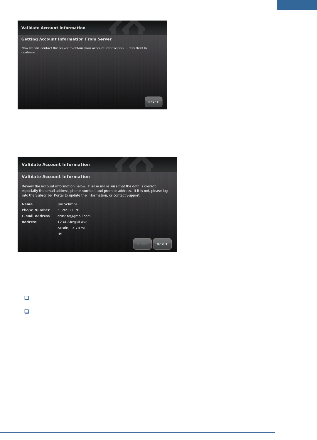
Step G: Setting and Validating the Security Information
The Master code is the keypad code that is required for the customer to access the Settings widget and
to create and manage other codes.
The Set Master Code is displayed.
Figure 33: Set Master Code Screen
1. Tap Next.
A keypad is displayed.
2. Enter a four-digit code twice, and tap Done.
The Getting Account Information From Server screen is displayed.
Home System Installation Guide
Installing the Security System
35
Figure 34: Validate Account Information: Getting Account Information From Server Screen
3. Tap Next.
The Validate Account Information screen is displayed.
Figure 35: Validate Account Information: Validate Account Information Screen
4. Ensure that the displayed account information for the customer is accurate—especially the fol-
lowing:
Phone number that the central monitoring station calls after an alarm
Email address that will receive an email necessary to perform the Subscriber Portal acti-
vation
Note: This information is associated with the Activation code you entered.
5. Tap Next.
The Getting Security Secret Word From Server screen is displayed.
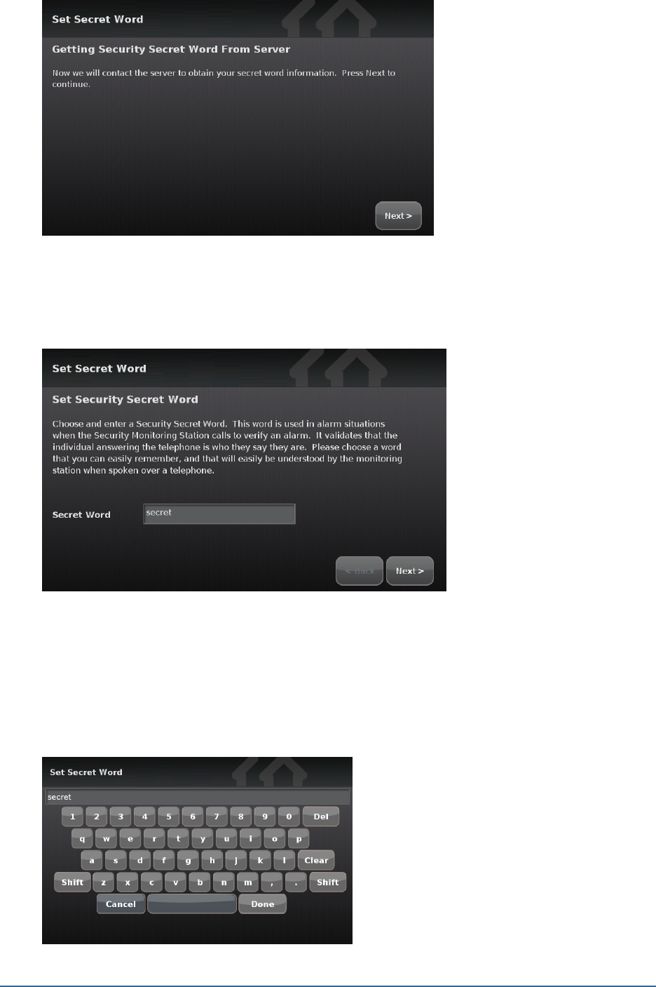
36
Figure 36: Set Secret Word: Getting Security Secret Word From Server Screen
6. Tap Next.
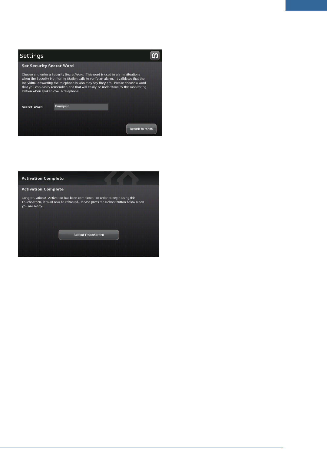
The Set Security Secret Word screen is displayed.
Figure 37: Set Secret Word: Set Security Secret Word Screen
7. Show the customer the secret word displayed on the screen. Explain that this is the word that
they will give to the central monitoring station when it calls to verify whether an alarm is false.
8. Tap the Secret Word field.
A keyboard screen is displayed.
Home System Installation Guide
Installing the Security System
37
9. Have the customer type a new secret word and then tap Done.
The Set Security Secret Word screen is displayed again.
10. Tap Next.
The Activation Complete screen is displayed.
Figure 38: Activation Complete Screen
11. Tap Reboot Touchscreen.
The TouchScreen reboots.

38
Step H: Mounting the Sensors
1. Mount the sensors and peripherals as described in the sensor documentation.
2. Test each sensor’s signal strength as described on page 63.
IMPORTANT: The minimum distance for the sensors to communicate with the TouchScreen is
beyond most practical limits. However, the distance can be limited occasionally by the
materials for the walls, electrical interference, and other conditions. To ensure a
strong signal from each sensor, test each sensor as described on page 44.
Home System Installation Guide
Installing the Security System
39
Step I: Configuring the TouchScreen
If necessary, perform the following operations:
Modify the Entry and Exit delay time periods (see page 48)
Modify the alarm transmission delay (see page 49)
Modify the “swinger shutdown” (see page 50)
Reset the TouchScreen to factory defaults (see page 50)
Note: This will cause the device to require activation again, which in turn will require that the
customer’s account be reset as well.
Check for a new firmware update (see page 52)
Manage the sensors/security zones (see Table 3: Sensor Operations on page 40)
Manage the cameras (see Table 4: Manage Camera Operations on page 40)
Manage key fobs and key pads (see Table 5: Manage Peripheral Operations on page 41)
Manage lights and thermostats (see Table 6: Manage Environmental Device Operations on page
41)
Technicians can also perform the following general activities that are also available to the customer.
Note: See the TouchScreen User Guide for information about these activities.
Manage the Quickarm settings.
Manage the way sensors are listed in TouchScreen reports and tools.
View and test the TouchScreen’s connectivity to the central monitoring stations.
Manage the keypad codes and secret word.
View the customer’s account information.
Manage your TouchScreen device sounds, screensaver, etc.
View technical information about the TouchScreen device.
40
Sensors consist of door/window sensors, motion detectors, glass break detectors, and smoke alarms.
Table 3: Sensor Operations
Operation Description
Modify sen-
sor details
Change (within limits) the details of a sensor (see page 1)
Delete a
sensor
Remove a camera from being man-
aged by the TouchScreen (see page
1).
Use these actions in sequence to reset a sen-
sor’s IP/MAC addresses to factory default
Add a sen-
sor
Find a new sensor that is available to
be added (see page 59)
Create a
cross zone
association
Configure two sensors to trip an alarm only if they are both faulted (see page 67);
For example, an alarm sounds when a door sensor is faulted ONLY if an associated
motion sensor also is faulted.
View sensor
diagnostics
View the connectivity details and signal strength of a sensor (see page 63)
Manage fire
alarm set-
tings
Toggle Fire Alarm Verification to
determine how the system triggers
fire alarms (see page 54
Disabled Central monitoring station is
contacted when one smoke
alarm sounds.
Enabled Central monitoring station is
notified when:
Multiple smoke detec-
tors sound an alarm
One smoke detector
sounds an alarm for
60 seconds
Table 4: Manage Camera Operations
Operation Description
Modify a camera
Change the name identifying each camera in the TouchScreen and the
Subscriber Portal.
Set or modify the zone to which the camera is assigned. When a camera is
assigned to a zone, the camera takes a series of pictures if that zone trips an
alarm.
Delete the camera
from the security
system
Remove a camera from being man-
aged by the TouchScreen (see page
1).
Use these actions in sequence to reset a
sensor’s IP/MAC addresses to factory
default
Add a camera to the
security system
Add an additional camera to the
TouchScreen – up to six (see page 1)
Replace a camera Swap the current camera with another one (see page 1)
Home System Installation Guide
Installing the Security System
41
Table 5: Manage Peripheral Operations
Operation Description
Delete a
key fob
Remove a key fob from being able to
access the security system (see page
1).
Use these actions in sequence to reset
a key fob’s details to factory default.
Add a key
fob
Find a new key fob that is available to
be added (see page 1).
Modify a
key fob
Change the name identifying each key fob in the TouchScreen and the Sub-
scriber Portal. (see page 1).
Delete a
key fob
Remove a key pad from being able to
access the security system (see page
1).
Use these actions in sequence to reset
a key pad’s details to factory default.
Add a key
pad
Find a new key pad that is available to
be added (see page 1).
Modify a
key pad
Change the name identifying each key pad in the TouchScreen and the Sub-
scriber Portal (see page 1).
Table 6: Manage Environmental Device Operations
Operation Description
Delete a lighting
device
Remove a lighting device from your system (see page 1).
Add a lighting
device
Pair a new lighting device to your system (see page 1).
Modify a lighting
device
Change the name identifying each key fob in the TouchScreen and the Subscriber
Portal. (see page 1).
Delete a ther-
mostat
Remove a thermostat from your system (see page 1).
Add a thermostat Pair a new thermostat to your system (see page 1).
Modify a ther-
mostat
Change the name identifying each key pad in the TouchScreen and the Subscriber
Portal (see page 1).

42
Step J: Activating the Subscriber Portal
1. With the customer, check the inbox for the email address of the customer’s account (the address
displayed on the Validate Account Settings screen).
The customer has received an email notification that their security system has been activated.
The email provides a temporary username and password to the Subscriber Portal. The
Subscriber Portal provides options for managing their account and security settings.
2. Note the temporary password in the email and tap the link in the email.
The Subscriber Portal login is displayed. The temporary username field is already filled in.
3. In the password field, enter the temporary password that was provided in the email.
Step 1 of the activation process is displayed.
4. Enter the Master code you set during the TouchScreen activation.
5. Tap Next.
Step 2 of the activation process is displayed.
6. Enter (twice) a username and a password that the customer will use to access the Subscriber Por-
tal.
7. Tap Next.
The Subscriber Portal is displayed.
8. Have the customer save the URL of the Subscriber Portal to the bookmarks in their browser.
Home System Installation Guide