Technisonic TDFM-136A VHF/FM Digital Airborne Transceiver User Manual 1
Technisonic Industries Limited VHF/FM Digital Airborne Transceiver 1
Contents
- 1. User Manual 1
- 2. User Manual 2
User Manual 1
VHF/FM DIGITAL
AIRBORNE TRANSCEIVER
MODEL TDFM-136A
Installation Instructions
TiL Document No.
09re404
Revision C Issue 1
JUNE 2009
Technisonic Industries Limited
240 Traders Boulevard, Mississauga, Ontario L4Z 1W7
Tel: (905) 890-2113 Fax: (905) 890-5338
www.til.ca

REVISIONS for 09re404 Sections 1 – 2
REV SECTION
- PAGE - DESCRIPTION DATE
A - Table 1-1
- STC Approv.
- Table 1-5
- FCC
Compliance
Changed operating temp to –30 to +60 C.
Change references of DO-160C to 160D.
Change Temp & Alt to B4 and D1.
Change Magnetic Effect to class Z.
Add FCC RF Exposure Requirements warning.
May 26/09
B - FCC
Compliance
- Table 1-4
- 2.5 Antenna
Installation.
- Footer, all
pages.
Change separation distance from 110cm to 1.0m.
Change RF Output Power Low to read “1W”.
Change 0dB to 3dBi and 20cm (8 inches) to 1.0m (40
inches).
Remove “and Operating” from “Installation and Operating
Instructions”.
June 15/09
C 2.5 Change antenna supplier & part number to
Comant Industries Inc. / Part No. CI 292-3
Jun 26/09
D 2-5 Fig 2-3 Wiring Connections (added ITEM 4) Aug 12/09
This page left intentionally blank.

TECHNISONIC INDUSTRIES LIMITED
www.til.ca
ESD CAUTION
This unit contains static sensitive devices. Wear a grounded wrist strap and/or conductive gloves
when handling printed circuit boards.
FCC COMPLIANCE INFORMATION
This device complies with Part 15 of the FCC Rules. Operation is subject to the following two conditions:
(1) this device may not cause harmful interference and (2) this device must accept any interference
received, including interference that may cause undesired operation.
WARNING: For compliance with FCC RF Exposure Requirements, the mobile transmitter antenna
installation shall comply with the following conditions:
1. The transmitter antenna gain shall not exceed 3 dBi.
2. The transmitter antenna is required to be located outside of a vehicle and kept at a
separation distance of 1.0 meter or more between the transmitter antenna of this device
and persons during operation.
NOTE: This equipment has been tested and found to comply with the limits for a Class B digital device,
pursuant to Part 15 of the FCC Rules. These limits are designed to provide reasonable protection
against harmful interference in a residential installation. This equipment generates, uses, and can
radiate radio frequency energy and, if not installed and used in accordance with the instruction
manual, may cause harmful interference to radio communications. However, there is no
guarantee that interference will not occur in a particular installation. If this equipment does cause
harmful interference to radio or television reception, which can be determined by turning the
equipment off and on, the user is encouraged to try to correct the interference by one or more of
the following measures:
• Re-orient or relocate the receiving antenna
• Increase the separation between the equipment and receiver
• Connect the equipment into an outlet or circuit different from that to which the receiver is
connected.
• Consult the dealer or an experienced radio/TV technician for help.
WARNING
Changes or modifications not expressly approved by Technisonic Industries could void the user’s
authority to operate the equipment.
WARRANTY INFORMATION
The Model TDFM-136A transceiver is under warranty for one year from date of purchase. Failed units
caused by defective parts, or workmanship should be returned to:
Technisonic Industries Limited
240 Traders Boulevard
Mississauga, Ontario L4Z 1W7
Tel: (905) 890-2113
Fax: (905) 890-5338
NOTICE: The above stated address supersedes all others that may appear otherwise in this manual.

TECHNISONIC INDUSTRIES LIMITED
www.til.ca
STC APPROVAL NOTE
Presently, no TSO standard exists for airborne FM transceivers. To make it easier for installation
agencies to provide their customers with an approved installation supported by an effective Airworthiness
Approval, Technisonic has secured Supplemental Type Certificate (STC) Approvals (both US and
Canadian) on its Airborne FM products for many helicopters currently being delivered in the US and
Canada as well as a number of single engine fixed wing aircraft. The above referenced DO-160D test
data is also on file and available from Technisonic to support approval requirements in airframes for
which Technisonic does not possess an STC.
Approved aircraft types are listed in the attachments to the formal STC documents. These STCs are the
exclusive property of Technisonic and require the written authority of Technisonic for their use. To assist
Factory Authorized Technisonic Dealers in the certification process, we have placed copies of our
Canadian and US STCs on our web site along with a letter of authorization for their use. These
documents may be downloaded and used as support for the technical submission to FAA or Transport
Canada. Only authorized factory dealers/installers are permitted to download and make use of these
documents on behalf of their customers (end users) in support of regulatory agency approval. Please
refer to the Technisonic web site www.til.ca for the latest issue of available STCs and letter of
authorization for use.
COPYRIGHT NOTICE
This document contains designs and other information which are the property of Technisonic Industries
Ltd. Except for rights expressly granted by contract to the Canadian Government, or to the United States
Government, this document may not, in whole or in part, be duplicated or disclosed or used for
manufacture of the part disclosed herein, without the prior permission of Technisonic Industries Ltd.
WARNING AND DISCLAIMER
This manual is designed to provide information about the TDFM-136A. Every effort has been made to
make this manual as complete and accurate as possible.

TECHNISONIC INDUSTRIES LIMITED
www.til.ca
TDFM-136A Installation Instructions Page v
TiL 09RE404 Rev C Issue 1
TABLE OF CONTENTS
SECTION TITLE PAGE
Table of Contents ............................................................................................................................. v
List of Figures ................................................................................................................................... vi
List of Tables .................................................................................................................................... vi
SECTION 1 GENERAL DESCRIPTION
1.1 Introduction ....................................................................................................................... 1-1
1.2 Description ........................................................................................................................ 1-1
1.3 Purpose of Equipment ...................................................................................................... 1-1
1.4 Model Variation ................................................................................................................. 1-2
1.5 Technical Characteristics ................................................................................................ 1-2
1.6 Certification Summary ...................................................................................................... 1-5
SECTION 2 OPERATING INSTRUCTIONS
2.1 General ............................................................................................................................... 2-1
2.2 Equipment Packing Log ................................................................................................... 2-1
2.3 Transceiver Installation .................................................................................................... 2-1
2.4 Installation Kit – Contents ................................................................................................ 2-1
2.5 Antenna Installation .......................................................................................................... 2-1
2.6 Installation - Pin Locations and Connections ................................................................ 2-2
2.7 Wiring Instructions ........................................................................................................... 2-4
2-7.1 Main Power +28VDC .................................................................................................... 2-4
2-7.2 Main Ground ................................................................................................................. 2-4
2-7.3 PTT (Ground Keying) ................................................................................................... 2-4
2-7.4 Front Panel Back Lighting ............................................................................................ 2-4
2-7.5 Audio Outputs (600 ohms and 4 0hms) ....................................................................... 2-4
2-7.6 Audio Output Ground ................................................................................................... 2-4
2-7.7 Mic Signal Input ............................................................................................................ 2-4
2-7.8 Memory Up/Memory Down .......................................................................................... 2-4
2-7.9 Data Input/Output ......................................................................................................... 2-4
2.8 Transmitter Side Tone Level Adjustment ....................................................................... 2-6
2.9 Main and Guard Noise Squelch Adjustment .................................................................. 2-6
2.10 Reference Layouts ............................................................................................................ 2-7
APPENDICES
APPENDIX A Post Installation EMI Test Instructions....................................................................... A-1
PURPOSE ................................................................................................................................ A-1
TEST CONDITIONS ................................................................................................................. A-1
METHODOLOGY ...................................................................................................................... A-1
RESULTS ................................................................................................................................. A-1
PROCEDURE ........................................................................................................................... A-2

TECHNISONIC INDUSTRIES LIMITED
www.til.ca
TDFM-136A Installation Instructions Page vi
TiL 09RE404 Rev C issue 1
LIST OF FIGURES
FIGURE TITLE PAGE
2-1 Transceiver Mounted View of the 15-Pin Connector .......................................................... 2-2
2-2 Outline Drawing for TDFM-136A Transceiver ..................................................................... 2-3
2-3 Wiring Connections for TDFM-136A Transceiver ............................................................... 2-5
2-4 Control points for the TDFM-136A MCU Board .................................................................. 2-7
LIST OF TABLES
TABLE TITLE PAGE
1-1 TDFM-136A – General Characteristics ............................................................................... 1-3
1-2 TDFM-136A – Operational Characteristics ......................................................................... 1-4
1-3 TDFM-136A – Receiver Characteristics – Main and Guard ............................................... 1-4
1-4 TDFM-136A – Transmitter Characteristics ......................................................................... 1-5
1-5 TDFM-136A – Environmental Testing Summary ................................................................ 1-5
2-1 TDFM-136A - Rear Connector Pin Assignments ................................................................ 2-2

TECHNISONIC INDUSTRIES LIMITED
www.til.ca
TDFM-136A Installation Instructions Page 1-1
TiL 09RE404 Rev C Issue 1
SECTION 1 - GENERAL
DESCRIPTION
1.1 INTRODUCTION
This publication provides operating and installation information for the TDFM-136A, Digital
Transceiver manufactured by Technisonic Industries Limited. The TDFM-136A is Project 25
(P25), Phase 1 compliant. The unit offers digital or conventional analog FM communications over
an extended frequency range with selectable channel spacing and is intended for use (in the
U.S.) only by government agencies or contractors thereto, who have obtained licensing for
operation in the 136-150 MHz portion of the band. If the TDFM-136A transceiver is used in
CANADA, operation is restricted to the following sub bands: 138-144, 148-148.99, 149.005-
150.005 and 150.05-174 MHz. Furthermore the frequency agile transceiver is restricted to
airborne use and must not be operated as a base station in Canada.
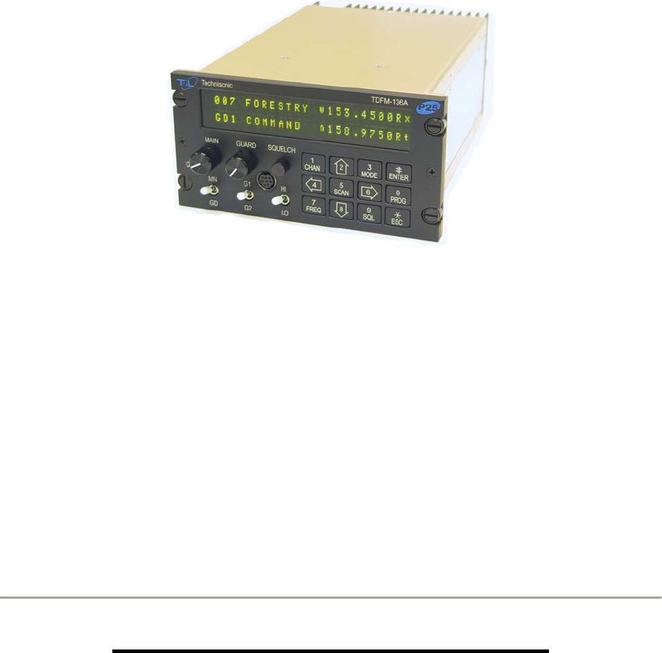
1.2 DESCRIPTION
The TDFM-136A, Transceiver is a frequency agile, fully synthesized airborne transceiver capable
of operating in the 136.000 MHz to 174.000 MHz frequency range in 2.5 kHz increments with
either 25 kHz analog, 12.5 kHz analog channel spacing and P25, 12.5 kHz digital modulation on
a channel by channel basis. The Transceiver can operate without restriction on any split
frequency pair in the band and also incorporates a two channel synthesized guard receiver.
The TDFM-136A Transceiver provides 230 operator accessible memory positions. Each of which
is capable of storing Scan List membership information, up to eight (8) character alphanumeric
identifier, and Operating Mode information. In addition each memory position contains information
for both transmit and receive including: frequency, CTCSS tone, DCS (DPL) code, P25
TalkGroup, and P25 Network Access Code (NAC) information.
Channel operating parameters, including frequency and other related data, are presented on a
48-character, two-line LED matrix display. Data entry and function control takes place via a 12-
button keypad.
1.3 PURPOSE OF EQUIPMENT
The TDFM-136A, Digital VHF/FM Transceiver is designed to provide secondary airborne
communications to facilitate operations which are typically performed in a low altitude
environment. The transmitter section of this unit has a minimum of 8 watts and does not exceed
10 watts output power, which may be reduced by a front panel switch to 1 watt, in order to reduce
interference to land based systems.

TECHNISONIC INDUSTRIES LIMITED
www.til.ca
TDFM-136A Installation Instructions Page 1-2
TiL 09RE404 Rev C Issue 1
1.4 MODEL VARIATION
There are twelve variations of the Model TDFM-136A Transceiver. All units offer identical
features and performance except for the following differences:
TDFM-136A, P/N 091258-1-10 GREEN display 28v back lighting, no Encryption.
TDFM-136A, P/N 091258-1-11 GREEN display 28v back lighting, with Encryption.
TDFM-136A, P/N 091258-2-10 RED display 28v back lighting, no Encryption.
TDFM-136A, P/N 091258-2-11 RED display 28v back lighting, with Encryption.
TDFM-136A, P/N 091258-3-10 NV display 28v back lighting, no Encryption.
TDFM-136A, P/N 091258-3-11 NV display 28v back lighting, with Encryption.
TDFM-136A, P/N 091258-4-10 GREEN display 5v back lighting, no Encryption.
TDFM-136A, P/N 091258-4-11 GREEN display 5v back lighting, with Encryption.
TDFM-136A, P/N 091258-5-10 RED display 5v back lighting, no Encryption.
TDFM-136A, P/N 091258-5-11 RED display 5v back lighting, with Encryption.
TDFM-136A, P/N 091258-6-10 NV display 5v back lighting, no Encryption.
TDFM-136A, P/N 091258-6-11 NV display 5v back lighting, with Encryption.

TECHNISONIC INDUSTRIES LIMITED
www.til.ca
TDFM-136A Installation Instructions Page 1-3
TiL 09RE404 Rev C Issue 1
1.5 TECHNICAL CHARACTERISTICS
The tables below provide the technical characteristics for the Technisonic Industries Ltd. Model
TDFM-136A.
TABLE 1-1 TDFM-136A – General Characteristics
Characteristic Specification
Dimensions (including heat sink) Approx. 8.0" X 3.0" X 5.75"
Weight Approx. 3.5 Lbs (1.6 Kg)
Mounting Panel Mount via DZUS fasteners
Power Requirement:
Voltage
Current
28.0 VDC, ±15%
Receive - 0.7 A Max.
Transmit Low Power (1W) - 1.3 A Max.
Transmit High Power (8-10W) - 2.0 A Max.
Audio Output Power:
Headset
Speaker Output
0.5 Watts into 600 ohms
2.5 Watts min. into 4 ohms
Back Lighting 28 Volts (standard)
5 Volts (specify)
Display Colour Green (standard)
Red (specify)
NVG (optional)
Temperature Range:
Operating
Storage
-30ºC to +60ºC
-55ºC to +85ºC
Altitude 50,000 feet

TECHNISONIC INDUSTRIES LIMITED
www.til.ca
TDFM-136A Installation Instructions Page 1-4
TiL 09RE404 Rev C Issue 1
TABLE 1-2 TDFM-136A – Operational Characteristics
Characteristic Specification
Frequency Range: 136.000 to 174.000 MHz
Operating Modes: Conventional analog: 12.5 / 25 kHz.
P25 CAI: 12 KBPS FSK, 9.6 KBPS C4FM
Channel Spacing: 25 kHz. or 12.5 kHz
Programmable Memories:
Scan Lists
Description
Operating Modes
Frequency
Squelch Modes
230 memories
15 scan lists
Up to 8 characters, alpha-numeric
Analog Wide, Analog Narrow, P25 Digital
Rx/Tx (Simplex/Duplex), 136.0000 – 174.0000
Rx/Tx (Simplex/Duplex), CTCSS Tones, DCS Codes,
P25 TalkGroup, P25 NAC
Guard Receiver:
Description
Operating Modes
Frequency
Squelch Modes
2 channels programmed with:
Up to 8 characters, alpha-numeric
Analog Wide, Analog Narrow, Digital
Rx/Tx (Simplex/Duplex), 136.0000 – 174.0000
MHz.
Rx/Tx (Simplex/Duplex), CTCSS Tones, DCS Codes,
P25 TalkGroup, P25 NAC
CTCSS Tones 42 CTCSS tones, including all standard tones.
DCS Codes All standard DCS (DPL1) codes
P25 TalkGroup $0000 to $FFFF ( 0 to 65535 )
P25 Network Access Code (NAC) $000 to $FFF ( 0 to 4095 )
DPL1 is a trademark of Motorola Corporation
TABLE 1-3 TDFM-136A – Receiver Characteristics – Main and Guard
Characteristic Specification
Sensitivity at 12 dB SINAD -116dBm
Adjacent Channel Selectivity -60dB (25 or 12.5 kHz)
Spurious Attenuation -70 dB
Third Order Intermodulation -70 dB
Image Attenuation -80 dB
FM Acceptance ± 6 kHz
Hum and Noise better than 45dB
Audio Distortion less than 5%
Antenna Conducted Emission less than -57dBm

TECHNISONIC INDUSTRIES LIMITED
www.til.ca
TDFM-136A Installation Instructions Page 1-5
TiL 09RE404 Rev C Issue 1
TABLE 1-4 TDFM-136A – Transmitter Characteristics
Characteristic Specification
RF Output Power:
Low
High
1W.
10W.
Output Impedance 50 ohms
Maximum Deviation:
Wide (25 kHz)
Narrow (12.5 kHz)
± 5 kHz
± 2.5 kHz
Maximum Deviation – Narrow ± 2.5 kHz (12.5 kHz mode)
Spurious Attenuation -90 dB below carrier level
Frequency Stability ± 2.5 ppm
Microphone Circuit Carbon or equivalent
Sidetone Output 0.5W (max) into 600 ohms
Harmonic Attenuation -65 dB below carrier level
FM Hum And Noise -40 dB
Audio Input 50 mV at 2.5 into 200 Ω input circuit for ± 3.5 deviation,
adjust.
Audio Distortion Less than 5%
1.6 CERTIFICATION SUMMARY
The following table gives a summary of DO-160D Environmental Testing for Technisonic Model
TDFM-136A, VHF Digital Transceiver.
TABLE 1-5 TDFM-136A – Environmental Testing Summary
Conditions Section Description of Conducted Tests
Temperature and Altitude 4.0 Equipment tested to categories B4 and D1.
Temperature Variation 5.0 Category B.
Humidity 6.0 Category A.
Operational Shock and Crash Safety 7.0 Category A.
Vibration 8.0 Equipment is tested without shock mounts to
categories S and U.
Magnetic Effect 15.0 Equipment is class Z.
Power Input 16.0 Category B.
Voltage Spike 17.0 Category B.
Audio Frequency Susceptibility 18.0 Category B.
Induced Signal Susceptibility 19.0 Category A.
Radio Frequency Susceptibility 20.0 Category U.
RF Emission (DO-160D)
RF Emission (DO-160C)
21.0 Category B.
Category Z.
Electrostatic Discharge 25.0 Category A.

TECHNISONIC INDUSTRIES LIMITED
www.til.ca
TDFM-136A Installation Instructions Page 1-6
TiL 09RE404 Rev C Issue 1
This page left intentionally blank.

TECHNISONIC INDUSTRIES LIMITED
www.til.ca
TDFM-136A Installation Instructions Page 2-1
TiL 09RE404 Rev C Issue 1
SECTION 2 – INSTALLATION INSTRUCTIONS
2.1 GENERAL
This section contains information and instructions for the correct installation of the
TDFM-136A, VHF/FM Digital Transceiver.
Make certain that the correct frequencies are pre-programmed in accordance with the equipment
user's valid FCC operator's license, prior to installation.
2.2 EQUIPMENT PACKING LOG
Unpack the equipment and check for any damage that may have occurred during transit. Save
the original shipping container for returns due to damage or warranty claims. Check that each
item on the packing slip has been shipped in the container. Verify that the equipment display and
back-lighting configuration are the same as those ordered.
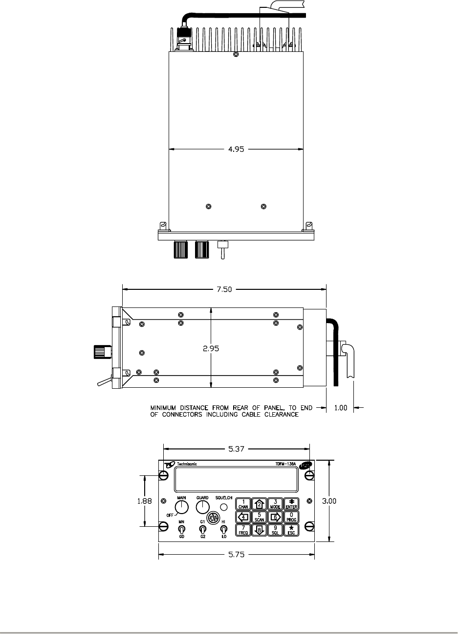
2.3 TRANSCEIVER INSTALLATION
The TDFM-136A Transceivers are designed to be Dzus mounted and should be installed in
conjunction with an IN-150 installation kit. See Figure 2-1 for an outline drawing of the unit with
dimensions to facilitate the installation.
2.4 INSTALLATION KIT - CONTENTS
The IN-150 installation kit consists of:
1. One 15-pin (female) Cannon D-mating connector complete with crimp pins and hoods.
2. One BNC antenna mating RF connector (male) and hood.
2.5 ANTENNA INSTALLATION
Antenna, P/N CI 292-3 may be obtained from Comant Industries Inc. or a suitable equivalent 3dBi
gain antenna may be used with the TDFM-136A transceivers. The antenna should be mounted
on the bottom of the aircraft whenever possible and must be located at least 1.0 meter (40
inches) from any occupant in the airframe. Consult with instructions provided with the antenna.
Connect RF cable from antenna to the back of the TDFM-136A unit by utilizing the BNC mating
connector provided in the installation kit.
2.6 INSTALLATION - PIN LOCATIONS AND CONNECTIONS
A single 15-pin DSUB connector, mounted on the rear of the unit, provides the means to connect
all power, control and audio signals between the TDFM-136A and the airframe. The pin numbers
and locations for the 15-pin DSUB connector are shown in figure 2-1 below. The view shown is of
the connector mounted in the unit, select mating connector appropriately.
FIGURE 2.1 Transceiver mounted view of 15-pin male connector

TECHNISONIC INDUSTRIES LIMITED
www.til.ca
TDFM-136A Installation Instructions Page 2-2
TiL 09RE404 Rev C Issue 1
Table 2-1 provides the description of the pin connections for the transceiver.
TABLE 2-1 TDFM-136A - Rear Connector Pin Assignments
Pin # Description Notes
1 Audio - Headset Output – 600 Ohms
2 Serial Data Out Output – RS232
3 Power - Panel Lighting 28 VDC Standard, 5VDC Optional
4 Signal - Memory Up Input – active low
5 Signal - Memory Down Input – active low
6 Audio - Microphone Input
7,14 Power - Main +28VDC Power
8,15 Power - Main Ground Power
9 Audio - Speaker 4-Ohm Speaker Output
10 Signal Ground 4-Ohm / 600-Ohm Output Ground
11 Serial Data In Input – RS232
13 Signal – PTT Input – active low
TECHNISONIC INDUSTRIES LIMITED
www.til.ca
TDFM-136A Installation Instructions Page 2-3
TiL 09RE404 Rev C Issue 1
(All dimensions in inches)
FIGURE 2-2 Outline Drawing for Model TDFM-136A Transceiver

TECHNISONIC INDUSTRIES LIMITED
www.til.ca
TDFM-136A Installation Instructions Page 2-4
TiL 09RE404 Rev C Issue 1
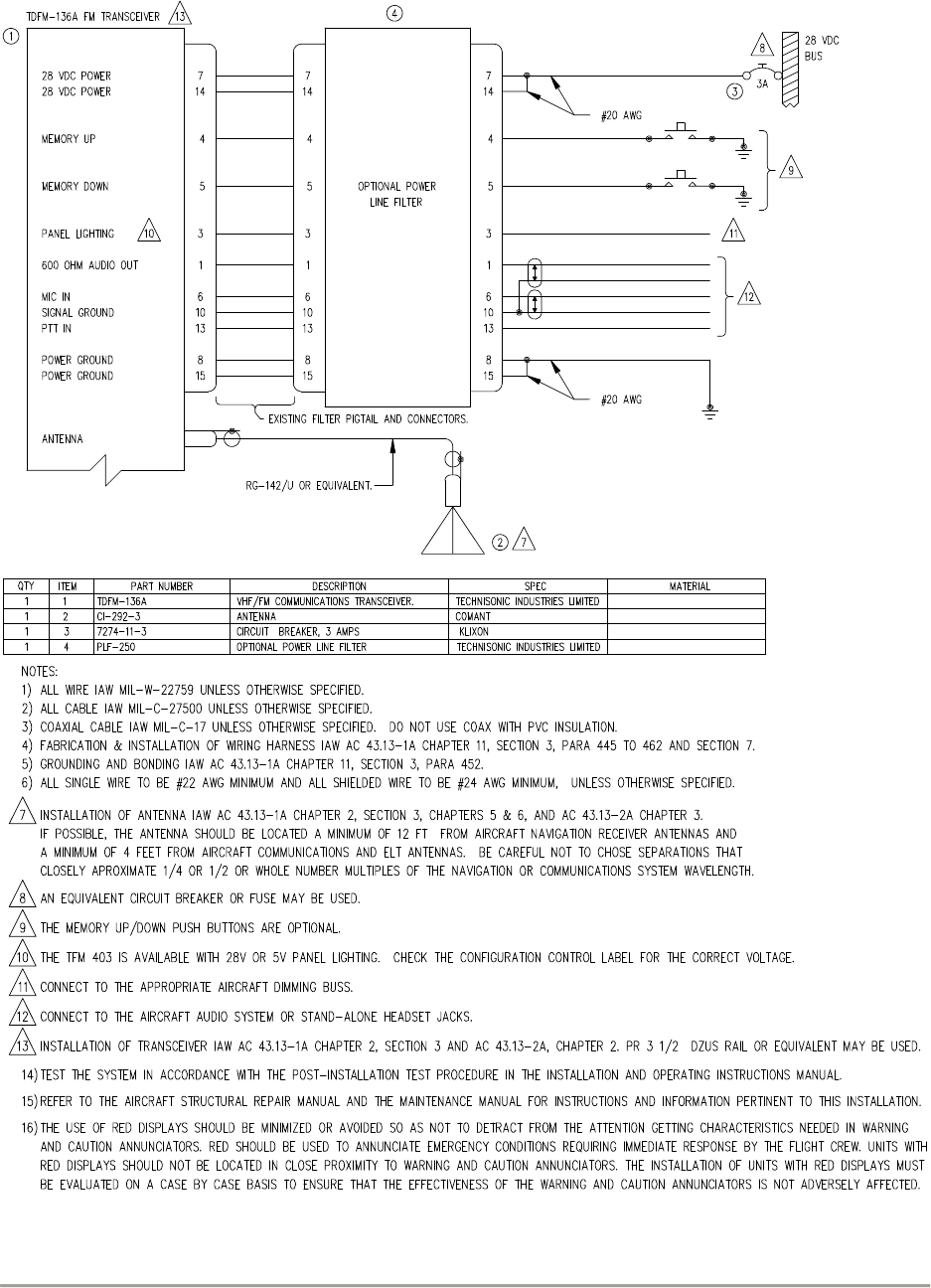
2.7 WIRING INSTRUCTIONS – 15-PIN D-CONNECTOR
Figure 2-3 shows all required connections and recommended wire sizes for the TDFM-136A
Transceiver operation in the airframe.
2.7.1 Main Power +28 VDC
The main power +28VDC (± 15%) is connected to pins 7 and 14 of the 15-pin D-connector on the
transceiver. Both pins should be connected.
2.7.2 Main Ground
Ground connections for the transceiver are made on pins 8 and 15. Both pins should be
connected.
2.7.3 PTT (Ground Keying)
The PTT line is connected to pin 13 and should be floating when the transceiver is in receive
mode, and grounded during transmit mode.
2.7.4 Front Panel Back Lighting
Front panel back lighting connection should be made on pin 3 of the transceiver. The opposite
end of this lead should be connected to the panel lighting system of the aircraft. Before
connecting, verify the required panel lighting voltage (28 VDC or 5 VAC) on the transceiver
configuration control label.
2.7.5 Audio Outputs (600 Ohms and 4 Ohms)
The audio output from pin 9 can be used to drive a 4 ohm speaker up to 2.5 watts. Audio output
from pin 1 is 600 Ohms, 0.5 watts maximum.
2.7.6 Audio Output Ground
Pin 10 is the ground for both the 4 and 600 Ohms audio output signals on pins 9 and 1.
2.7.7 Mic Signal Input
The microphone input signal is to be provided on pin 6, utilizing shielded wire with the shield
grounded to pin 10.
2.7.8 Memory Up/Memory Down
Remote scrolling through the 25 memory positions can be achieved by providing a ground to pins
4 (up) and 5 (down) through a momentary contact cyclic switch.
2.7.9 Data Input
Channel data may be transferred to and from the unit using RS-232 communications protocol via
pins 2 and 11.
TECHNISONIC INDUSTRIES LIMITED
www.til.ca
TDFM-136A Installation Instructions Page 2-5
TiL 09RE404 Rev C Issue 1
Figure 2-3 Wiring Connections for TDFM-136A Transceiver

TECHNISONIC INDUSTRIES LIMITED
www.til.ca
TDFM-136A Installation Instructions Page 2-6
TiL 09RE404 Rev C Issue 1
2.8 TRANSMITTER SIDE TONE LEVEL ADJUSTMENT
The side tone level is set at the factory; however, this level can be altered to suit local conditions
as follows:
1. Set the transceiver operating frequency to 155.000 MHz and connect an appropriate test
receiver to the RF output connector. Ensure that the output of the transceiver is terminated
into a proper dummy load.
2. Key the transmitter and input a 1 kHz audio signal @ -10 dBm (0.25 VRMS) into the
microphone input.
3. Select the side-tone adjust command (L2-7) and then adjust the side-tone level using the
up/down arrows (keys 2 & 8) to produce a +3.0 dBm (1.0 VRMS) 600 Ohm audio output.
2.9 MAIN AND GUARD NOISE SQUELCH ADJUSTMENT
The squelch (on both the main and guard receivers) is factory set to open at approximately 0.5
micro-volts. This adjustment can be altered to suit local conditions as follows:
1. Set the main receiver of the transceiver to 155.000 MHz. Connect a signal generator to
the antenna input of the transceiver.
2. Set the signal generator to produce a ± 3 deviation with a 1 kHz tone on 156.000 MHz.
Increase the signal generator RF level from 0.1 uV until the squelch indicator LED is on.
Verify the receiver SINAD ratio is between 12 and 14 dB.
3. If not, re-adjust main receiver squelch via the main receiver squelch software command.
4. Repeat the above procedure to adjust the guard receiver squelch setting using guard
receiver squelch adjustment software command.
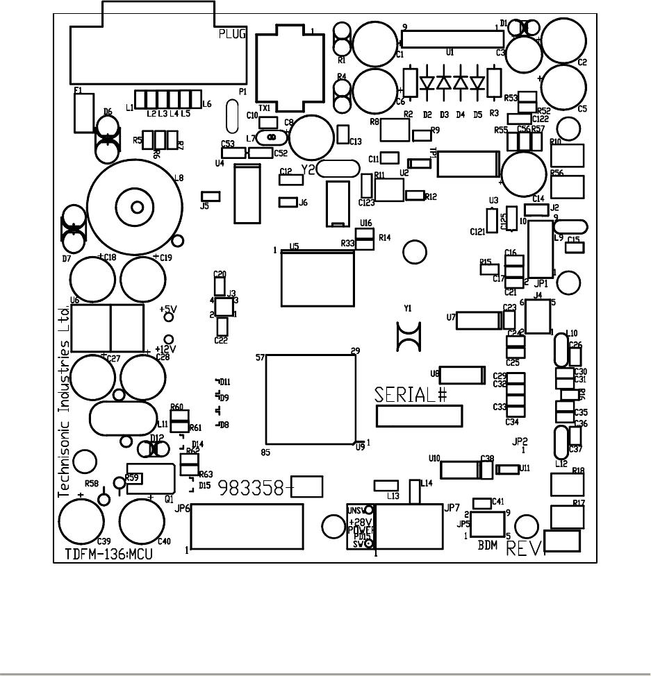
2.10 REFERENCE LAYOUTS
A reference layout indicating the position of control points for the MCU board is shown in Figure
2-4.
TECHNISONIC INDUSTRIES LIMITED
www.til.ca
TDFM-136A Installation Instructions Page 2-7
TiL 09RE404 Rev C Issue 1
J2: Boot Program Enable - factory set DO NOT INSTALL
J4: Option Jumpers:
1-2 Maintenance Mode Enable - DO NOT INSTALL IN AIRFRAME, BENCH ONLY
2-4 Factory Use Only – DO NOT INSTALL
5-6 n/u reserved
R8: Main Rx Audio adjust - factory set
R10: Tx Mic Audio Level Adjust – factory set
R11: Guard Rx Audio adjust – factory set
R17: RF Low power adjust – factory set
R18: RF High power adjust – factory set
R56: DTMF Level Adjust – factory set
FIGURE 2-4 Control points for the TDFM-136A MCU Board

TECHNISONIC INDUSTRIES LIMITED
www.til.ca
TDFM-136A Installation Instructions Page 2-8
TiL 09RE404 Rev C Issue 1
This page left intentionally blank

TECHNISONIC INDUSTRIES LIMITED
www.til.ca
TDFM-136A Installation Instructions Page A-1
TiL 09RE404 Rev C Issue 1
APPENDIX A – POST INSTALLATION EMI TEST INSTRUCTIONS”
PURPOSE
The purpose of these tests is to identify any interference that the TDFM-136A may cause with
existing aircraft systems.
TEST CONDITIONS
The TDFM-136A transceiver should be installed and function tested. The antenna VSWR should
be checked. A forward/reverse power check with an in-line wattmeter should show no more than
10% reflected power. For the following tests, insure that the power switch is in the high position.
METHODOLOGY
Most of the EMI tests can be accomplished on the ground. In some cases flight testing is required
or is easier. If the aircraft is approved for IFR operations, then it is mandatory that interference
between the TDFM-136A Airborne FM and the approach aids be checked in flight.
The GPS should be operational and navigating with at least the minimum compliment of
satellites. The VHF COMM should be set to the frequencies indicated with the squelch open.
VOR/DME receivers should be set to the frequencies indicated and selected for display. If
possible, set up a DME ramp test set on the frequencies indicated and adjust the output until the
flags are out of view. The transponder and encoder should be monitored with ramp test
equipment. Set the output of the transponder test set to 3db above the output necessary to
achieve 90% reply. If possible set the ADF to a nearby navigation station.
Modulate the TDFM-136A transmitter on the indicated frequencies for at least 20 seconds.
Observe the GPS for any degradation in satellite status or availability or flags. Listen for any
noise or detected audio signals on the VHF COMM(s). Listen for any noise or detected audio
signals on the VOR/LOC receiver audio; look for any movement of flags or needles on the
VOR/LOC/GS navigation display(s). Observe the transponder for any loss of reply or spurious
reply.
List the power plant, fuel and other electric instruments in the chart provided and note any
anomalies that occur while transmitting. Assess the results.
If the aircraft is equipped with an auto-pilot or a stability augmentation system, then test fly the
aircraft and verify that operation of the TDFM-136A transceiver does not have adverse effects on
these systems. After checking for gross effects at a safe altitude, fly an approach with each of the
different navigation systems coupled to the auto-pilot (ILS, GPS etc.) and look for any anomalies.
RESULTS
If the installed system passes all of the applicable EMI tests, then no further action is required. If
interference is observed, then the interference must be assessed against the appropriate
standards of airworthiness for the system in question. For example, it is permissible for a VFR
certified GPS to lose navigation capability while the TDFM-136A is transmitting providing that it
recovers properly and promptly, but is not permissible for an IFR approach certified GPS to be
affected in the same way. A complete discussion of all the standards of airworthiness to be
applied in assessing EMI effects is beyond the scope of this document.

TECHNISONIC INDUSTRIES LIMITED
www.til.ca
TDFM-136A Installation Instructions Page A-2
TiL 09RE404 Rev C Issue 1
PROCEDURE
A. Operate the TDFM-136A transmitter on the following frequency for at least 20 seconds. Observe
the GPS for any degradation in satellite status or availability or flags.
FREQUENCIES GPS #1 GPS #2
TDFM-136A PASS FAIL PASS FAIL
143.1800 MHz
143.1825 MHz
157.5000 MHz
157.5425 MHz
NOTES:

TECHNISONIC INDUSTRIES LIMITED
www.til.ca
TDFM-136A Installation Instructions Page A-3
TiL 09RE404 Rev C Issue 1
B. Determine if the image frequency for the VHF COMM falls within the range of the TDFM-136A. If
so, select a set of frequencies that will cause the TDFM-136A to be set as close as possible to
the image frequency. Any one of the many possible sets will suffice. Record those values in the
spaces provided in the following chart. Modulate the TDFM-136A transmitter on the following
frequencies for at least 20 seconds. Listen for any noise or detected audio signals on the VHF
Comm.
EXAMPLE: Bendix/King KY 196A.
The first IF frequency is 11.4 MHz. The LO is above the receive frequency (high side injection).
Therefore, the image frequency is 22.8 MHz above the selected frequency. Set the KY 196A to
120.000 MHz and the TDFM-136A to 142.8000 MHz.
FREQUENCIES RESULTS
VHF #1 TDFM-136A PASS FAIL
135.975 MHz 135.975 MHz
121.150 MHz 121.150 MHz
131.250 MHz 131.250 MHz
Image
FREQUENCIES RESULTS
VHF #2 TDFM-136A PASS FAIL
138.0000 MHz 138.0000 MHz
157.5000 MHz 157.5000 MHz
157.5000 MHz 157.5000 MHz
Image
NOTES:

TECHNISONIC INDUSTRIES LIMITED
www.til.ca
TDFM-136A Installation Instructions Page A-4
TiL 09RE404 Rev C Issue 1
C. Determine if the image frequency for the VOR/ILS Nav falls within the range of the TDFM-136A. If
so, select two sets of frequencies that will cause the TDFM-136A to be set a close as possible to
the image frequency. Chose one set in the localizer frequency range and one in the VOR
frequency range. Record those values in the spaces provided in the following chart. Modulate the
TDFM-136A transmitter on the following frequencies for at least 20 seconds. Listen for any noise
or detected audio signals on the receiver audio; look for any moment of flags or needles on the
navigation display.
FREQUENCIES RESULTS
VOR / ILS #1 TDFM-136A PASS FAIL
108.000 MHz 162.0000 MHz
108.100 MHz 162.1500 MHz
Image
Image
FREQUENCIES RESULTS
VOR / ILS #2 TDFM-136A PASS FAIL
108.000 MHz 162.0000 MHz
108.100 MHz 162.1500 MHz
Image
Image
NOTES:

TECHNISONIC INDUSTRIES LIMITED
www.til.ca
TDFM-136A Installation Instructions Page A-5
TiL 09RE404 Rev C Issue 1
D. Modulate the TDFM-136A transmitter on the following frequencies for at least 20 seconds.
Observe the Glide Slope displays. Look for any movement of flags or needles on the Navigation
display.
FREQUENCIES RESULTS
Glide slope #1 TDFM-136A PASS FAIL
334.7 (108.1) 167.3500 MHz
FREQUENCIES RESULTS
Glide slope #2 TDFM-136A PASS FAIL
334.7 (108.1) 167.3500 MHz
NOTES:

TECHNISONIC INDUSTRIES LIMITED
www.til.ca
TDFM-136A Installation Instructions Page A-6
TiL 09RE404 Rev C Issue 1
For the following tests (E & F), select a frequency at the top, middle and bottom of the band of the
TDFM-136A Transceiver.
VHF Band (138 to 174 MHz)
Frequency No. 1
Frequency No. 2
Frequency No. 3
E. At a safe altitude engage the autopilot or stability augmentation system. Modulate the TDFM-
136A on the above frequencies for at least 20 seconds. Observe any effect on the autopilot or
stability augmentation system.
Observations:
F. Perform a coupled ILS approach to the aircraft’s certified limits. Modulate the TDFM-136A
transmitter on the above frequencies for at least 20 seconds. Observe any effect on the autopilot.
Repeat for second flight director/autopilot if so equipped.
Observations:

TECHNISONIC INDUSTRIES LIMITED
www.til.ca
TDFM-136A Installation Instructions Page A-7
TiL 09RE404 Rev C Issue 1
G. List the power plant, fuel and other electric instruments in the chart provided and note any
anomalies that occur while transmitting. Assess the results.
STEP SYSTEM PASS FAIL NOTES
1 COMM 1 and 2
2 Transponder and Encoder
3 ADF 1 and 2
4 Vertical Gyro
5 Glide slope 1 and 2
6 VOR/LOC 1 and 2
7 Directional Gyro
8 Compass
9 Fuel Pressure
10 Oil Temperature
11 Ammeter
12 Bus Voltage
13 Fuel
14 Nt
15 TOT
16 % Torque
17 Digital Clock
18 Oil Pressure
19 Annunciators

TECHNISONIC INDUSTRIES LIMITED
www.til.ca
TDFM-136A Installation Instructions Page A-8
TiL 09RE404 Rev C Issue 1
STEP SYSTEM PASS FAIL NOTES
NOTES: