Technisonic TDFM-136B VHF/FM Digital Airborne Transceiver User Manual VHF FM
Technisonic Industries Limited VHF/FM Digital Airborne Transceiver VHF FM
Contents
- 1. User Manual 1
- 2. User Manual 2
User Manual 1
TDFM-136B
VHF/FM DIGITAL AIRBORNE TRANSCEIVER
INSTALLATION INSTRUCTIONS
Til Document No. 08RE398
Rev. N/C
Issue 2
DEC 2010
Technisonic Industries Limited
240 Traders Blvd. E. Mississauga, Ontario L4Z 1W7 Tel: (905) 890-2113 Fax: (905) 890-5338
3840 E. Robinson road, Suite 214, Amherst, New York 14228 Tel: (716) 691-0669
This document contains designs and other information which are the property of Technisonic Industries Ltd. Except for rights expressly
granted by contract to the Canadian Government, or to the United States Government, this document may not, in whole or in part, be
duplicated or disclosed or used for manufacture of the part disclosed herein, without the prior permission of Technisonic Industries Ltd.

TDFM-136B Installation Instructions 08RE398
! CAUTION STATIC S E N S IT IV E !
This unit contains static sensitive devices. Wear a grounded wrist strap and/or conductive gloves
when handling printed circuit boards.
FCC COMPLIANC E
This device complies with Part 15 of the FCC Rules. Operation is subject to the following two
conditions: (1) this device may not cause harmful interference and (2) this device must accept any
interference received, including interference that may cause undesired operation.
WARNING: For compliance with FCC RF Exposure Requirements, the mobile transmitter antenna
installation shall comply with the following two conditions:
1. The transmitter antenna gain shall not exceed 3 dBi.
2. The transmitter antenna is required to be located outside of a vehicle and
kept at a separation distance of 1.0 meter or more between the transmitter
antenna of this device and persons during operation.
NOTE: This equipment has been tested and found to comply with the limits for a Class B digital
device, pursuant to Part 15 of the FCC Rules. These limits are designed to provide reasonable
protection against harmful interference in a residential installation. This equipment generates,
uses, and can radiate radio frequency energy and, if not installed and used in accordance
with the instruction manual, may cause harmful interference to radio communications.
However, there is no guarantee that interference will not occur in a particular installation. If
this equipment does cause harmful interference to radio or television reception, which can be
determined by turning the equipment off and on, the user is encouraged to try to correct the
interference by one or more of the following measures:
• Re-orient or relocate the receiving antenna
• Increase the separation between the equipment and receiver
• Connect the equipment into an outlet or circuit different from that to which the
receiver is connected.
• Consult the dealer or an experienced radio/TV technician for help.
WARNING: Changes or modifications not expressly approved by Technisonic Industries could
void the user's authority to operate the equipment.
WARR A NTY INFORMATION
The Model TDFM-136B, VHF/FM Digital Transceiver is under warranty for one year from date of
purchase. Failed units caused by defective parts, or workmanship should be returned to:
Technisonic Industries Limited Technisonic Industries Limited
240 Traders Blvd., 3840 E. Robinson Road, Suite 214
Mississauga, Amherst,
Ontario L4Z 1W7 New York 14228
Tel: (905) 890-2113 Tel: (716) 691-0669
Fax: (905) 890-5338
iii

08RE398 TDFM-136B Installation Instructions
STC APPROVALS
Presently no TSO standard exists for airborne FM transceivers. To make it easier for installation
agencies to provide their customers with an approved installation supported by an effective
Airworthiness Approval, Technisonic has secured Supplemental Type Certificate (STC) approvals
(both US and Canadian) on it’s airborne FM products for many helicopters currently being
delivered in the US and Canada, as well as a number of single engine fixed wing aircraft. The DO-
160C test data, referenced below, are also on file and available from Technisonic to support
approval requirements in airframes for which Technisonic does not possess an STC.
Approved aircraft types are listed in the attachments to the formal STC documents. These STC’s
are the exclusive property of Technisonic Industries Ltd., and require the written authority of
Technisonic for their use. To assist Factory Authorized Technisonic Dealers in the certification
process, we have placed copies of our Canadian and US STC’s on our web site along with a letter
of authorization for their use. These documents may be downloaded and used as support for the
technical submission to FAA or Transport Canada. Only factory authorized dealers/installers are
permitted to download and make use of these documents on behalf of their customers (end users)
in support of regulatory agency approval. please refer to the Technisonic web site www.til.ca for
the latest issue of available STC’s and letter of authorization for use.
iv

TDFM-136B Installation Instructions 08RE398
Document Revision Table for 08RE398
Rev.
/
Issue
Page Description Date Appr.
v

08RE398 TDFM-136B Installation Instructions
Table of Contents
Table of Contents............................................................................................................................vi
Table of Tables...............................................................................................................................vii
Table of Figures..............................................................................................................................vii
SECTION 1 - GENERAL DESCRIPTION ....................................................................................1-1
1.1 Introduction......................................................................................................................1-1
1.2 Description........................................................................................................................1-1
1.3 Purpose of Equipment......................................................................................................1-1
1.4 Model Variation.................................................................................................................1-2
1.5 Technical Characteristics..................................................................................................1-2
1.6 Certification Summary......................................................................................................1-4
SECTION 2 - INSTALLATION INSTRUCTIONS .........................................................................2-1
2.1 General.............................................................................................................................. 2-1
2.2 Equipment Packing Log.....................................................................................................2-1
2.3 Transceiver Installation .....................................................................................................2-1
2.4 Installation Kit - Contents...................................................................................................2-1
2.5 Antenna Installation ..........................................................................................................2-1
2.6 Installation - Pin Locations and Connections.....................................................................2-2
2.7 Wiring Instructions.............................................................................................................2-4
2.7.1 Main Power +28VDC..................................................................................................2-4
2.7.2 Main Ground..............................................................................................................2-4
2.7.3 PTT (Ground Keying).................................................................................................2-4
2.7.4 Front Panel Back Lighting..........................................................................................2-4
2.7.5 Audio Outputs (600 ohms and 4 0hms)......................................................................2-4
2.7.6 Audio Output Ground ................................................................................................2-4
2.7.7 Mic Signal Input..........................................................................................................2-4
2.7.8 Memory Up/Memory Down.........................................................................................2-6
2.7.9 Data Input/Output.......................................................................................................2-6
2.8 Transmitter Side Tone Level Adjustment...........................................................................2-6
2.9 Main and Guard Noise Squelch Adjustment......................................................................2-6
2.10 Reference Layouts...........................................................................................................2-7
SECTION 3 - APPENDICIES ......................................................................................................3-1
3.1 Appendix A CTCSS TONE TABLES and DCS CODE TABLES........................................3-1
3.2 Appendix B - POST INSTALLATION EMI TEST INSTRUCTIONS....................................3-2
3.2.1 PURPOSE..................................................................................................................3-2
3.2.2 TEST CONDITIONS..................................................................................................3-2
3.2.3 METHODOLOGY.......................................................................................................3-2
3.2.4 RESULTS...................................................................................................................3-3
3.2.5 PROCEDURE............................................................................................................3-4
vi

TDFM-136B Installation Instructions 08RE398
Ta ble of Figures
Figure 2-1. Transceiver Mounted View of the 15 Pin Connector.................................................2-2
Figure 2-2. Wiring Connections for TDFM-136B Transceiver.......................................................2-3
Figure 2-3. Outline Drawing for TDFM-136B Transceiver............................................................2-4
Figure 2-4. Control points for the TDFM-136B MCU Board..........................................................2-7
Ta ble of Tables
Table 1-1. TDFM-136B – Model Variation....................................................................................1-2
Table 1-2. TDFM-136B – General Characteristics.......................................................................1-2
Table 1-3. TDFM-136B – Operational Characteristics.................................................................1-3
Table 1-4. TDFM-136B – Receiver Characteristics – Main and Guard........................................1-3
Table 1-5. TDFM-136B – Transmitter Characteristics..................................................................1-4
Table 1-6. TDFM-136B – Environmental Testing Summary.........................................................1-4
Table 3-1. TDFM-136B - Rear Connector Pin Assignments.........................................................2-2
vii
08RE398 TDFM-136B Installation Instructions
viii

S EC T ION 1
GENERAL DESCR IPT IO N
1.1 Introduction
This publication provides operating and installation information for the TDFM-136B, Digital
Transceiver manufactured by Technisonic Industries Limited. The TDFM-136B is Project
25 (P25), Phase 1 compliant. The unit offers digital or conventional analog FM
communications over an extended frequency range with selectable channel spacing and is
intended for use (in the U.S.) only by government agencies or contractors thereto, who
have obtained licensing for operation in the 136-150 MHz portion of the band. If the TDFM-
136B transceiver is used in CANADA, operation is restricted to the following sub bands:
138-144, 148-148.99, 149.005-150.005 and 150.05-174 MHz. Furthermore the frequency
agile transceiver is restricted to airborne use and must not be operated as a base station in
Canada.
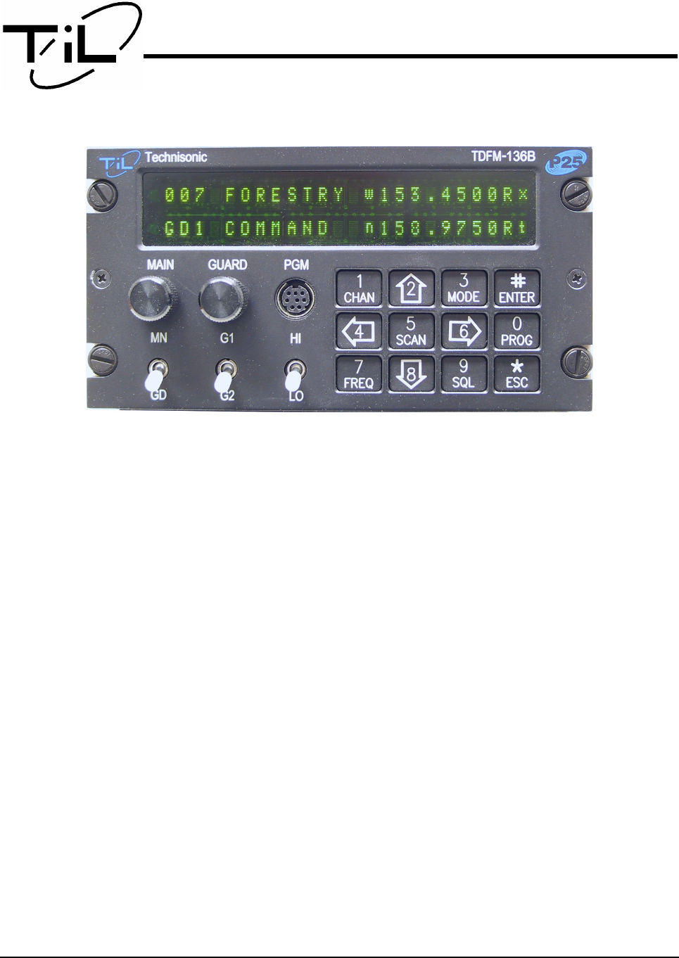
1.2 Description
The TDFM-136B, Transceiver is a frequency agile, fully synthesized airborne transceiver
capable of operating in the 136.000 MHz to 174.000 MHz frequency range in 2.5kHz
increments with either 25 kHz analog, 12.5 kHz analog channel spacing and P25, 12.5 kHz
digital modulation on a channel by channel basis. The Transceiver can operate without
restriction on any split frequency pair in the band and also incorporates a two channel
synthesized guard receiver.
The TDFM-136B Transceiver provides 230 operator accessible memory positions. Each of
which is capable of storing Scan List membership information, up to eight (8) character
alphanumeric identifier, and Operating Mode information. In addition each memory position
contains information for both transmit and receive including: frequency, CTCSS tone, DCS
(DPL) code, P25 TalkGroup, and P25 Network Access Code (NAC) information.
Channel operating parameters, including frequency and other related data, are presented
on a 48 character, two line LED matrix display. Data entry and function control takes place
via a 12 button keypad.
1.3 Purpose of Equipment
The TDFM-136B, Digital VHF/FM Transceiver is designed to provide secondary airborne
communications to facilitate operations which are typically performed in a low altitude
environment. The transmitter section of this unit has a minimum of 8 watts and does not
exceed 10 watts output power, which may be reduced by a front panel switch to 1 watt, in
order to reduce interference to land based systems.
Technisonic Industries Ltd. 1-1
08RE398 TDFM-136B Installation Instructions
1.4 Model Variation
The base Part Number for the Model TDFM-136B is 081252, there are three parameters
that affect model variation: display lighting, number of antennae, and encryption operation.
The possible combinations result in 12 possible extensions to the base part number, these
are shown in Table 1-1 below.
Table 1-1. TDFM-136B – Model Variation
Parameter Part Number
Display Lighting Antennae Encryption Capable
Green Single No 081252-1-10
Green Single Yes 081252-1-11
Green Dual No 081252-1-20
Green Dual Yes 081252-1-21
Red Single No 081252-2-10
Red Single Yes 081252-2-11
Red Dual No 081252-2-20
Red Dual Yes 081252-2-21
N/V Single No 081252-3-10
N/V Single Yes 081252-3-11
N/V Dual No 081252-3-20
N/V Dual Yes 081252-3-21
1.5 Technical Characteristics
The tables below provide the technical characteristics for the Technisonic Industries Ltd.
Model TDFM-136B.
Table 1-2. TDFM-136B – General Characteristics
Characteristic Specification
Dimensions (including heat sink) Approx. 8.0" X 3.0" X 5.75"
Weight Approx. 3.5 Lbs (1.6 Kg)
Mounting Panel Mount via DZUS fasteners
Power Requirement:
Voltage
Current
28.0 VDC, ±15%
Receive - 0.7 A Max.
Transmit Low Power (1W) - 1.3 A Max.
Transmit High Power (8-10W) - 2.0 A Max.
Audio Output Power:
Headset
Speaker Output
0.5 Watts into 600 ohms
2.5 Watts min. into 4 ohms
Back Lighting 28 Volts / 5 Volts
Display Colour Green (standard)
Red (specify)
NVG (specify)
Temperature Range:
Operating
Storage
-45ºC to +70ºC
-55ºC to +85ºC
Altitude 50,000 feet
1-2 Technisonic Industries Ltd.

TDFM-136B Installation Instructions 08RE398
Table 1-3. TDFM-136B – Operational Characteristics
Characteristic Specification
Frequency Range 136.000 to 174.000 MHz
Operating Modes conventional Analog: 12.5 / 25 kHz.
P25 CAI: 12 KBPS FSK, 9.6 KBPS C4FM
Channel Spacing: 25 kHz. or 12.5 kHz
Programmable Memories:
Scan Lists
Description
Operating Modes
Frequency
Squelch Modes
230 memories
15 scan lists
Up to 8 characters, alpha-numeric
Analog Wide, Analog Narrow, P25 Digital
Rx/Tx (Simplex/Duplex), 136.0000 – 174.0000
Rx/Tx (Simplex/Duplex), CTCSS Tones, DCS Codes,
P25 TalkGroup, P25 NAC
Guard Receiver:
Description
Operating Modes
Frequency
Squelch Modes
2 channels programmed with:
Up to 8 characters, alpha-numeric
Analog Wide, Analog Narrow, Digital
Rx/Tx (Simplex/Duplex), 136.0000 – 174.0000 MHz.
Rx/Tx (Simplex/Duplex), CTCSS Tones, DCS Codes,
P25 TalkGroup, P25 NAC
CTCSS Tones 42 CTCSS tones, including all standard tones.
DCS Codes All standard DCS (DPL*) codes
P25 TalkGroup $0000 to $FFFF ( 0 to 65535 )
P25 Network Access Code (NAC) $000 to $FFF ( 0 to 4095 )
* DPL is a trademark of Motorola Corporation
Table 1-4. TDFM-136B – Receiver Characteristics – Main and Guard
Characteristic Specification
Sensitivity at 12 dB SINAD -116dBm
Adjacent Channel Selectivity -60dB (25 or 12.5 kHz)
Spurious Attenuation -70 dB
Third Order Intermodulation -70 dB
Image Attenuation -80 dB
FM Acceptance ± 6 kHz
Hum and Noise Better than 45dB
Audio Distortion less than 5%
Antenna Conducted Emission less than -57dBm
Technisonic Industries Ltd. 1-3

08RE398 TDFM-136B Installation Instructions
Table 1-5. TDFM-136B – Transmitter Characteristics
Characteristic Specification
RF Output Power:
Low
High
1 watt
10 watts
Output Impedance 50 ohms
Maximum Deviation:
Wide (25 kHz)
Narrow (12.5 kHz)
± 5 kHz
± 2.5 kHz
Maximum Deviation – Narrow ± 2.5 kHz (12.5 kHz mode)
Spurious Attenuation -90 dB below carrier level
Frequency Stability ± 2.5 ppm
Microphone Circuit Carbon or equivalent
Side-tone Output 0.5W (max) into 600ohms
Harmonic Attenuation -65 dB below carrier level
FM Hum And Noise -40 dB
Audio Input 50 mV at 2.5 into 200Ω input circuit for ± 3.5
deviation, adjust.
Audio Distortion Less than 5%
1.6 Certification Summary
The following table gives a summary of DO-160D Environmental Testing for Technisonic
Model TDFM-136B, VHF Digital Transceiver.
Table 1-6. TDFM-136B – Environmental Testing Summary
Conditions Section Conducted Test
Temperature and Altitude 4.0 Equipment tested to Categories B2 and D1.
Temperature Variation 5.0 Category B.
Humidity 6.0 Category A.
Operational Shock and Crash
Safety
7.0 Category A.
Vibration 8.0 Equipment is tested without shock mounts to
categories S and U.
Magnetic Effect 15.0 Equipment is class A.
Power Input 16.0 Category B.
Voltage Spike 17.0 Category B.
Audio Frequency Susceptibility 18.0 Category B.
Induced Signal Susceptibility 19.0 Category A.
Radio Frequency Susceptibility 20.0 Category U.
RF Emission (DO-160D)
RF Emission (DO-160C)
21.0
21.0
Category B.
Category Z.
Electrostatic Discharge 25.0 Category A.
1-4 Technisonic Industries Ltd.

S E C T I O N 2
INSTALLATION INST RUCT IONS
This section contains information and instructions for the correct installation of the TDFM-
136B, VHF/FM Digital Transceiver.
Make certain that the correct frequencies are pre-programmed in accordance with the
equipment user's valid FCC operator's license, prior to installation.
2.1 Equipment Packing Log
Unpack the equipment and check for any damage that may have occurred during transit.
Save the original shipping container for returns due to damage or warranty claims. Check
that each item on the packing slip has been shipped in the container. Verify that the
equipment display and back-lighting configuration are the same as those ordered.
2.2 Transceiver Installation
The TDFM-136B Transceivers are designed to be Dzus mounted and should be installed in
conjunction with a IN-150 installation kit. See Figure 2-3 for an outline drawing of the unit
with dimensions to facilitate the installation.
2.3 Installation Kit - Contents
The IN-150 installation kit consists of:
1. One 15 pin Cannon D mating connector (female) complete with crimp pins and hood.
2. One BNC antenna mating RF connector (male) and hood.
2.4 Antenna Installation
Antenna, P/N CI-292, or a suitable equivalent, may be used with the TDFM-136B
transceivers. The antenna should be mounted on the bottom of the aircraft whenever
possible and must be located at least 1.0 meter (40 inches) from any occupant in the
airframe. Consult the instructions provided with the antenna. Connect RF cable from
antenna to the back of the TDFM-136B unit by utilizing the BNC mating connector provided
in the installation kit.
Technisonic Industries Ltd. 2-1
08RE398 TDFM-136B Installation Instructions
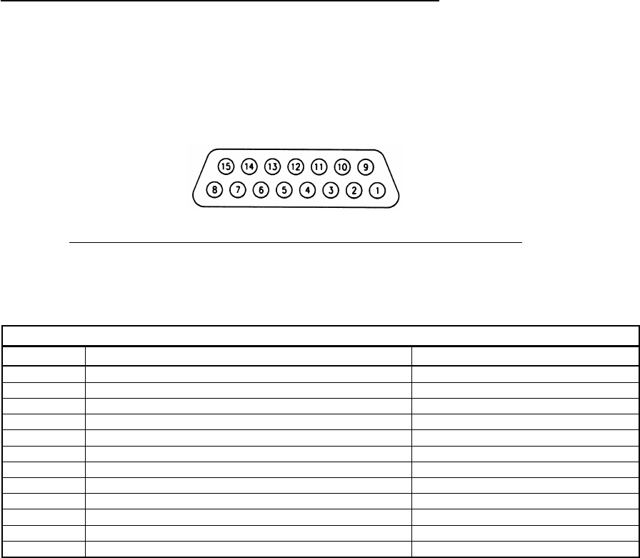
2.5 Installation - Pin Locations and Connections
A single 15 pin DSUB connector, mounted on the rear of the unit, provides the means to
connect all power, control and audio signals between the TDFM-136B and the airframe.
The pin numbers and locations for the 15 pin DSUB connector are shown in figure 2-1
below. The view shown is of the connector mounted in the unit, select mating connector
appropriately.
Figure 2-1. Transceiver Mounted View of the 15 Pin Connector
The description of the pin connections for the transceiver are in provided in TABLE 3-1.
Table 3-1. TDFM-136B - Rear Connector Pin Assignments
Pin # Description Notes
1 Audio - Headset output – 600 ohm
2 Serial Data Out output – RS232
3 Power - Panel Lighting 28VDC standard, 5VDC option
4 Signal - Memory Up input – active low
5 Signal - Memory Down input – active low
6 Audio - Microphone input
7, 14 Power - Main +28VDC power
8, 15 Power - Main Ground power
9 Audio - Speaker output – 4 ohm
10 Signal Ground
11 Serial Data In input – RS232
13 Signal – PTT input – active low
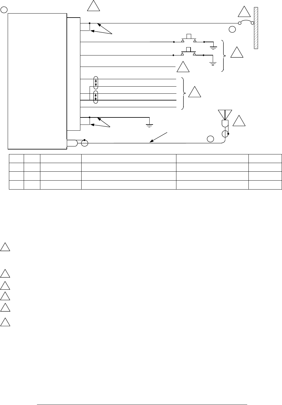
Detailed wiring information is supplied in figure 2-2 below.
2-2 Technisonic Industries Ltd.
TDFM-136B Installation Instructions 08RE398
QTY
ITEM
PART NUMBER
DESCRIPTION
SPEC
MATERIAL
1 1 TDFM-136B VHF/FM COMMUNICATIONS TRANSCEIVER TECHNISONIT INDUSTIRES LTD.
1 2 CI-292 ANTENNA COMANT INDUSTRIES
1 3 11/03/74 CIRCUIT BREAKER, 3A KLIXON
Figure 2-2. Detailed Wiring Connections for TDFM-136B Transceiver
Technisonic Industries Ltd. 2-3
28 VDC POWER 7
28 VDC POWER 14
MEMORY UP 4
MEMORY DOWN 5
PANEL LIGHTING 3
600 ohm AUDIO OUT 1
MIC IN 6
SIGNAL GROUND 10
PTT IN 13
POWER GROUND 8
POWER GROUND 15
ANTENNA
TDFM-136B FM TRANSCEIVER
7
#20 AWG 3
1
2
28 VDC
BUS
8
9
#20 AWG
10
12
11
3A
RG-142/U OR
EQUIVALENT
NOTES:
1) ALL WIRE IAW MIL-W-22579 UNLESS OTHERWISE SPECIFIED.
2) ALL CABLE IAW MIL-C-27500 UNLESS OTHERWISE SPECIFIED.
3) COAXIAL CABLE IAW MIL-C-17 UNLESS OTHERWISE SPECIFIED. DO NOT USE COAX WITH PVC INSULATION.
4) FABRICATION & INSTALLATION OF WIRING HARNESS IAW AC 43.13-1A CHAPTER 11, SECTION 3, PARA 445 TO 462 AND SECTION 7.
5) GROUNDING AND BONDING IAW AC 43.13-1A CHAPTER 11, SECTION 3, PARA 452.
6) ALL SINGLE WIRE TO BE #22 AWG MINIMUM AND ALL SHIELDED WIRE TO BE #24 AWG MINIMUM, UNLESS OTHERWISE SPECIFIED.
INSTALLATION OF ANTENNA IAW AC 43.13-1A CHAPTER 2, SECTION 3, CHAPTERS 5&6, AND AC43.13-2A CHAPTER 3.
IF POSSIBLE, THE ANTENNA SHOULD BE LOCATED A MINIMUM OF 12 FT FROM AIRCRAFT NAVIGATION RECEIVER ANTENNAS AND
A MINIMUM OF 4 FEET FROM AIRCRAFT COMMNICATIONS AND ELT ANTENNAS. BE CAREFUL NOT TO CHOSE SEPARATIONS THAT
CLOSELY APPROXIMATE ¼ OR ½ OR WHOLE NUMBER MULTIPLES OF THE NAVIGATION OR COMMUNICATIONS SYSTEM WAVELENGTH.
AN EQUIVALENT CIRCUIT BREAKER OR FUSE MAY BE USED.
THE MEMORY UP/DOWN PUSH BUTTONS ARE OPTIONAL.
CONNECT TO THE APPROPRIATE AIRCRAFT DIMMING BUSS.
CONNECT TOTHE AIRCRAFT AUDIO SYSTEM OR STAND-ALONE HEADSET JACKS.
INSTALLATION OF TRANSCEIVER IAW AC 43.13-1A CHAPTER 2, SECTION E AND AC 43.13-2A, CHAPTER 2. PR 3 1/2 DZUS RAIL
OR EQUIVALENT MAY BE USED.
13) TEST THE SYSTEM IN ACCORDANCE WITH THE POST-INSTALLTION TEST PROCEDURE IN THE INSTALLATION MANUAL.
14) REFER TO THE AIRCRAFT STRUCTURAL REPAIR MANUAL AND THE MAINTENANCE MANUAL FOR INSTRUCTIONS AND
INFORMATION PERTINENT TO THIS INSTALLATION.
15) THE USE OF RED DISPLAYS SHOULD BE MINIMIZED OR AVOIDED SO AS NOT TO DETRACT FROM THE ATTENTION GETTING
CHARACTERISTICS NEEDED IN WARNING AND CAUTION ANNUNCIATORS. RED SHOULD BE USED TO ANNUNCIATE EMERGENCY
CONDITIONS REQUIRING IMMEDIATE RESPONSE BY THE FLIGHT CREW. UNITS WITH RED DISPLAYS SHOULD NOT BE LOCATED
IN CLOSE PROXIMITY TO WARNING AND CAUTION ANNUNCIATORS. THE INSTALLATION OF UNITS WITH RED DISPLAYS MUST BE
EVALUATED ON A CASE BY CASE BASIS TO ENSURE THAT THE EFFECTIVENESS OF THE WARNING AND CAUTION ANNUNCIATORS
IS NOT ADVERSELY AFFECTED.
7
8
9
10
11
12
08RE398 TDFM-136B Installation Instructions
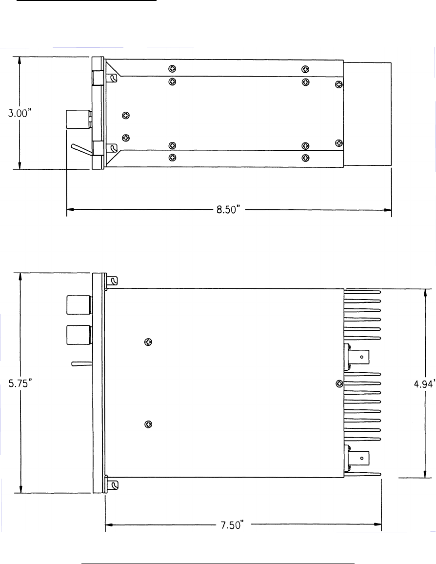
2.6 Physical Dimensions
Figure 2-3 below shows the physical dimensions of the unit
Figure 2-3. Outline Drawing for TDFM-136B Transceiver
2-4 Technisonic Industries Ltd.

TDFM-136B Installation Instructions 08RE398
2.7 Wiring Instructions
Figure 2-3 shows all required connections and recommended wire sizes for the TDFM-
136B Transceiver operation in the airframe.
2.7.1 Main Power +28VDC
The main power +28VDC (±15%) is connected to pins 7 and 14 of the transceiver. Both
pins should be connected.
2.7.2 Main Ground
Ground connections for the transceiver are made on pins 8 and 15. Both pins should be connected
2.7.3 PTT (Ground Keying)
The PTT line is connected to pin 13 and should be floating when the transceiver is in receive mode,
and grounded during transmit mode.
2.7.4 Front Panel Back Lighting
Front panel back lighting connection should be made on pin 3 of the transceiver. The opposite end
of this lead should be connected to the panel lighting system of the aircraft. Before connecting, verify
the required panel lighting voltage, the unit is compatible with both 28V and 5V lighting bus voltages.
2.7.5 Audio Outputs (600 ohms and 4 0hms)
The audio output from pin 9 can be used to drive a 4 ohm speaker up to 2.5 watts. Audio output
from pin 1 is 600 ohms, 0.5 watts maximum.
2.7.6 Audio Output Ground
Pin 10 is the ground for both the 4 ohm and 600 ohm audio output signals on pins 9 and 1.
2.7.7 Mic Signal Input
The microphone input signal is to be provided on pin 6, utilising shielded wire with the shield
grounded to pin 10.
2.7.8 Memory Up/Memory Down
Remote scrolling through the memory positions can be achieved by providing a ground to pins 4 (up)
and 5 (down) through a momentary contact cyclic switch.
2.7.9 Data Input/Output
Channel data may be transferred to and from the unit using RS-232 communications protocol via
pins 2 and 11.
Technisonic Industries Ltd. 2-5

08RE398 TDFM-136B Installation Instructions
2.8 Transmitter Side Tone Level Adjustment
The side tone level is set at the factory and there is no hardware adjustment. However, this
level can be altered, via the radio software, to suit local conditions as follows:
1. Set the transceiver operating frequency to 155.0000 MHz and connect an appropriate test
receiver to the RF output connector. Ensure that the output of the transceiver is terminated
into a proper dummy load.
2. Key the transmitter and input a 1 kHz audio signal @ -10 dBm (0.25 VRMS) into the
microphone input.
3. Select the Side-Tone Adjust command, and then adjust the side-tone level using the
up/down arrows (keys 2 & 8) to produce a +3.0 dBm (1.0 VRMS) at the 600 ohm audio
output (headset output).
2.9 Main and Guard Noise Squelch Adjustment
The squelch on both the main and guard receivers is factory set to open at approximately
0.5 microvolts, there is no hardware adjustment. However, this value can be altered, via
the radio software, to suit local conditions as follows:
1. Set the main receiver of the transceiver to 155.000 MHz. Connect a signal generator to the
antenna input of the transceiver.
2. Set the signal generator to produce a ± 3 deviation with a 1 kHz tone on 156.0000 MHz.
Increase the signal generator RF level from 0.1 uV until the squelch indicator LED is on.
Verify the receiver SINAD ratio is between 12 and 14 dB.
3. If not, re-adjust main receiver squelch via the Edit Squelch software command.
4. Repeat the above procedure to adjust the guard receiver squelch setting using guard
receiver squelch adjustment software command.
2-6 Technisonic Industries Ltd.
TDFM-136B Installation Instructions 08RE398
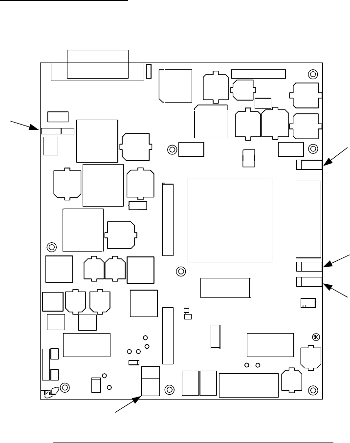
2.10 Reference Layouts
The reference layout shown in figure 3-4 below, shows the position of jumper control points
for the MCU board.
Figure 2-4. Control points for the TDFM-136B MCU Board
JP1: Front Panel Power Switch bypass jumper. Insert a shunt to power unit with no front panel
attached. Default: no shunt installed.
JP3: Serial Communications Protocol Select Jumper:
1-3 & 2-4: RS-485 - default
3-5 & 4-6: RS-232
all other combinations are invalid.
P3: factory use only, no shunt installed
P4: factory use only, no shunt installed
P5: Restricted Access Lock Select.
Technisonic Industries Ltd. 2-7
059582F
JP3
JP1
P3
P4
P5
Technisonic Industries Ltd. 2-8
S E C T I O N 3
App e n d i c i e s
3.1 Appendix A CTCSS TONE TABLES and DCS CODE TABLES
Available CTCSS Tones Available DCS Codes
Tone Code Code
67 23 315
69.3 25 331
71.9 26 343
74.4 31 346
77 32 351
79.7 43 364
82.5 47 365
85.4 51 371
88.5 54 411
91.5 65 412
94.8 71 413
97.4 72 423
100 73 431
103.5 74 432
107.2 114 445
110.9 115 464
114.8 116 465
118.8 125 466
123 131 503
127.3 132 506
131.8 134 516
136.5 143 532
141.3 152 546
146.2 155 565
151.4 156 606
156.7 162 612
162.2 165 624
167.9 172 627
173.8 174 631
179.9 205 632
186.2 223 654
192.8 226 662
203.5 243 664
206.5 244 703
210.7 245 712
218.1 251 723
225.7 261 731
229.1 263 732
233.6 265 734
241.8 271 743
250.3 306 754
254.8 311
Technisonic Industries Ltd. 3-1
08RE398 TDFM-136B Installation Instructions
3.2 APPENDIX B - POST INSTALLATION EMI TEST INSTRUCTIONS
3.2.1 PURPOSE
The purpose of these tests is to identify any interference that the TDFM-136B may cause
with existing aircraft systems.
3.2.2 TEST CONDITIONS
The TDFM-136B transceiver should be installed and function tested. The antenna VSWR
should be checked. A forward/reverse power check with an in-line wattmeter should show
no more than 10% reflected power. For the following tests, insure that the power switch is
in the high position.
3.2.3 METHODOLOGY
Most of the EMI tests can be accomplished on the ground. In some cases flight testing is
required or is easier. If the aircraft is approved for IFR operations, then it is mandatory that
interference between the TDFM-136B Airborne FM and the approach aids be checked in
flight.
The GPS should be operational and navigating with at least the minimum compliment of
satellites. The VHF comm should be set to the frequencies indicated with the squelch
open. VOR/DME receivers should be set to the frequencies indicated and selected for
display. If possible, set up a DME ramp test set on the frequencies indicated and adjust
the output until the flags are out of view. The transponder and encoder should be
monitored with ramp test equipment. Set the output of the transponder test set to 3db
above the output necessary to achieve 90% reply. If possible set the ADF to a nearby
navigation station.
Modulate the TDFM-136B transmitter on the indicated frequencies for at least 20 seconds.
Observe the GPS for any degradation in satellite status or availability or flags. Listen for
any noise or detected audio signals on the VHF comm(s). Listen for any noise or detected
audio signals on the VOR/LOC receiver audio; look for any movement of flags or needles
on the VOR/LOC/GS navigation display(s). Observe the transponder for any loss of reply
or spurious reply.
List the power plant, fuel and other electric instruments in the chart provided and note any
anomalies that occur while transmitting. Assess the results.
If the aircraft is equipped with an auto-pilot or a stability augmentation system, then test fly
the aircraft and verify that operation of the TDFM-136B transceiver does not have adverse
effects on these systems.
After checking for gross effects at a safe altitude, fly an approach with each of the different
navigation systems coupled to the auto-pilot (ILS,GPS etc.) and look for any anomalies.
3-2 Technisonic Industries Ltd.
TDFM-136B Installation Instructions 08RE398
3.2.4 RESULTS
If the installed system passes all of the applicable EMI tests, then no further action is
required. If interference is observed, then the interference must be assessed against the
appropriate standards of airworthiness for the system in question. For example, it is
permissible for a VFR certified GPS to lose navigation capability while the TDFM-136B is
transmitting providing that it recovers properly and promptly, but is not permissible for an
IFR approach certified GPS to be affected in the same way. A complete discussion of all
the standards of airworthiness to be applied in assessing EMI effects is beyond the scope
of this document.
Technisonic Industries Ltd. 3-3

08RE398 TDFM-136B Installation Instructions
3.2.5 PROCEDURE
A. Operate the TDFM-136B transmitter on the following frequency for at least 20 seconds.
Observe the GPS for any degradation in satellite status or availability or flags.
Frequencies GPS #1 GPS #2
Pass Fail Pass Fail
143.1800 MHz
143.1825 MHz
157.5000 MHz
157.5425 MHz
NOTES:
3-4 Technisonic Industries Ltd.

TDFM-136B Installation Instructions 08RE398
B. Determine if the image frequency for the VHF Comm falls within the range of the TDFM-136B. If so,
select a set of frequencies that will cause the TDFM-136B to be set as close as possible to the image
frequency. Any one of the many possible sets will suffice. Record those values in the spaces
provided in the following chart. Modulate the TDFM-136B transmitter on the following frequencies for
at least 20 seconds. Listen for any noise or detected audio signals on the VHF Comm.
Example – Bendix/King KY 196A;
The first IF frequency is 11.4 MHz. The L.O. is above the receive frequency (high side injection),
therefore the image frequency is 22.8 MHz above the selected frequency. Set the KY 196A to
120.000 MHz and the TDFM-136B to 142.8000 MHz.
Frequencies Results
VHF #1 TDFM-136B Pass Fail
135.975 MHz 138.0000 MHz
121.150 MHz 157.5000 MHz
131.250 MHz 157.5000 MHz
Image
Frequencies Results
VHF #2 TDFM-136B Pass Fail
135.975 MHz 138.0000 MHz
121.150 MHz 157.5000 MHz
131.250 MHz 157.5000 MHz
Image
NOTES:
Technisonic Industries Ltd. 3-5

08RE398 TDFM-136B Installation Instructions
C. Determine if the image frequency for the VOR/ILS Nav falls within the range of the TDFM-
136B. If so, select two sets of frequencies that will cause the TDFM-136B to be set a close
as possible to the image frequency. Chose one set in the localizer frequency range. and
one in the VOR frequency range. Record those values in the spaces provided in the
following chart. Modulate the TDFM-136B transmitter on the following frequencies for at
least 20 seconds. Listen for any noise or detected audio signals on the receiver audio;
look for any moment of flags or needles on the navigation display.
Frequencies Results
VOR / ILS #1 TDFM-136B Pass Fail
108.000 MHz 162.0000 MHz
108.100 MHz 162.1500 MHz
Image
Image
Frequencies Results
VOR / ILS #2 TDFM-136B Pass Fail
108.000 MHz 162.0000 MHz
108.100 MHz 161.1500 MHz
Image
Image
NOTES:
3-6 Technisonic Industries Ltd.

TDFM-136B Installation Instructions 08RE398
D. Modulate the TDFM-136B transmitter on the following frequencies for at least 20 seconds.
Observe the Glide Slope displays. Look for any movement of flags or needles on the
Navigation display.
Frequencies Results
Glide slope #1 TDFM-136B Pass Fail
334.7 (108.1) 167.3500 MHz
Frequencies Results
Glide slope #2 TDFM-136B Pass Fail
334.7 (108.1) 167.3500 MHz
NOTES:
Technisonic Industries Ltd. 3-7

08RE398 TDFM-136B Installation Instructions
For the following tests (E & F), select a frequency at the top, middle and bottom of the
band of the TDFM-136B Transceiver.
VHF Band (138 to 174 Mhz)
Frequency No. 1
Frequency No. 2
Frequency No. 3
E. At a safe altitude engage the autopilot or stability augmentation system. Modulate the
TDFM-136B on the above frequencies for at least 20 seconds. Observe any effect on the
autopilot or stability augmentation system.
Observations:
F. Perform a coupled ILS approach to the aircraft’s certified limits. Modulate the TDFM-136B
transmitter on the above frequencies for at least 20 seconds. Observe any effect on the
autopilot. Repeat for second flight director/autopilot if so equipped.
Observations:
3-8 Technisonic Industries Ltd.

TDFM-136B Installation Instructions 08RE398
G. List the power plant, fuel and other electric instruments in the chart provided and note any
anomalies that occur while transmitting. Assess the results.
Step System Pass Fail Notes
1 Comm 1 and Comm 2
2 Transponder and Encoder
3 ADF 1 and 2
4 Vertical Gyro
5 Glide slope 1 and 2
6 VOR/LOC 1 and 2
7 Directional Gyro
8 Compass
9 Fuel Pressure
10 Oil Temperature
11 Ammeter
12 Bus Voltage
13 Fuel
14 Nt
15 TOT
16 % Torque
17 Digital Clock
18 Oil Pressure
19 Annunciators
Technisonic Industries Ltd. 3-9

08RE398 TDFM-136B Installation Instructions
Step System Pass Fail Notes
20
21
22
23
24
25
26
27
NOTES:
3-10 Technisonic Industries Ltd.