Technisonic TDFM-136B VHF/FM Digital Airborne Transceiver User Manual VHF FM
Technisonic Industries Limited VHF/FM Digital Airborne Transceiver VHF FM
Contents
- 1. User Manual 1
- 2. User Manual 2
User Manual 2
TDFM-136B
VHF/FM DIGITAL AIRBORNE TRANSCEIVER
OPERATING INSTRUCTIONS
Til Document: 08RE399
Rev. N/C
OCT 2010
Technisonic Industries Limited.
copyright © 2010 Technisonic Industries Ltd. All rights reserved.
TDFM-136B Operating Instructions 08RE399
ii

08RE399 TDFM-136B Operating Instructions
CONTACT US
Technisonic Industries Limited
240 Traders Blvd. E.
Mississauga, Ontario.
L4Z 1W7
tel: (905) 890-2113
fax: (905) 890-5338
web: www.til.ca
SCOPE of MAN UAL
This document provides Operating Instructions for TDFM-136B transceivers with firmware:
Release 1.0.0 This manual does not include transceiver installation instructions. For installation
instructions please see Technisonic document: 08RE398.
FCC COMPL IANC E INFORMAT ION
This device complies with Part 15 of the FCC Rules. Operation is subject to the following two
conditions: (1) this device may not cause harmful interference and (2) this device must accept any
interference received, including interference that may cause undesired operation.
WARNING: For compliance with FCC RF Exposure Requirements, the mobile transmitter antenna
installation shall comply with the following conditions:
1. The transmitter antenna gain shall not exceed 3 dBi.
2. The transmitter antenna is required to be located outside of a vehicle and kept at a
separation distance of 1.0 meter or more between the transmitter antenna of this device
and persons during operation.
NOTE: This equipment has been tested and found to comply with the limits for a Class B digital device,
pursuant to Part 15 of the FCC Rules. These limits are designed to provide reasonable protection
against harmful interference in a residential installation. This equipment generates, uses, and can
radiate radio frequency energy and, if not installed and used in accordance with the instruction
manual, may cause harmful interference to radio communications. However, there is no guarantee
that interference will not occur in a particular installation. If this equipment does cause harmful
interference to radio or television reception, which can be determined by turning the equipment off
and on, the user is encouraged to try to correct the interference by one or more of the following
measures:
-Re-orient or relocate the receiving antenna
-Increase the separation between the equipment and receiver
-Connect the equipment into an outlet or circuit different from that to which the receiver is
connected.
-Consult the dealer or an experienced radio/TV technician for help.
WARNING:
Changes or modifications not expressly approved by Technisonic Industries could void the
user’s authority to operate the equipment.
WA RRANTY INF ORMATION
The Model TDFM-136B, VHF/FM Digital Transceiver is under warranty for one year from date of
purchase. Failed units caused by defective parts, or workmanship should be returned to:
Technisonic Industries Limited
240 Traders Blvd. E,
Mississauga, Ontario.
L4Z 1W7
iii

TDFM-136B Operating Instructions 08RE399
Document Revision Table for 08RE399
Rev. /
Issue Page Description Date Change
By
iv

08RE399 TDFM-136B Operating Instructions
Ta ble of C ontents
SECTION1 ......................................................................................................................................1
1.1 Controls and Display..............................................................................................................1
1.1.1 Front Panel Layout and Controls....................................................................................1
1.1.2 Channel Parameter Display............................................................................................2
1.2 Transceiver Basic Operation..................................................................................................3
1.2.1 Selecting the Active Channel – Main or Guard...............................................................3
1.2.2 Selecting a Main Channel Memory.................................................................................4
1.3 About Commands..................................................................................................................5
1.3.1 Command Levels............................................................................................................5
1.3.2 Command Types............................................................................................................6
1.3.3 Command Groups..........................................................................................................6
1.3.4 Command Reference.....................................................................................................6
SECTION 2 .....................................................................................................................................7
2.1 Channel Operating Parameters .............................................................................................7
2.1.1 Memory Parameters.......................................................................................................7
2.2 Editing Channel Operating Parameters .................................................................................7
2.2.1 The Frequency Parameter..............................................................................................9
2.2.2 Operating Modes..........................................................................................................10
2.2.3 Squelch Modes.............................................................................................................11
2.2.4 ID Call Operation..........................................................................................................15
2.3 Scan and Multi-Mode Operation ..........................................................................................16
2.3.1 Scan Operation............................................................................................................16
2.3.2 Multi-Mode Operation...................................................................................................17
2.4 Controlling User Access ......................................................................................................18
2.4.1 Control Access to Command Levels.............................................................................18
2.4.2 Set Command Permissions..........................................................................................19
2.4.3 Control Access to Squelch Modes................................................................................21
2.4.4 Control Editing of Memories.........................................................................................21
2.4.5 Control Display of Frequency Information.....................................................................22
2.5 Encrypted Operation ...........................................................................................................23
2.5.1 Loading Encryption Keys..............................................................................................23
2.5.2 Assign KeyTag to Encryption Keys...............................................................................23
2.5.3 Assign Key by KeyTag to Memory................................................................................24
2.5.4 Enable/Disable Encrypted Operation............................................................................26
SECTION 3 ....................................................................................................................................27
3.1 Operator Level 1 Commands ..............................................................................................28
3.1.1 Select the Operating Memory for the Main Channel.....................................................28
3.1.2 Increase Display Brightness.........................................................................................28
3.1.3 Edit Channel Operating Mode......................................................................................28
3.1.4 Scroll Backwards through Available Memories.............................................................29
3.1.5 Start/Stop Scan............................................................................................................29
v
TDFM-136B Operating Instructions 08RE399
3.1.6 Scroll Backwards through Available Memories.............................................................30
3.1.7 Edit Channel Operating Frequency...............................................................................30
3.1.8 Decrease Display Brightness........................................................................................31
3.1.9 Edit Channel Squelch Mode.........................................................................................31
3.1.10 Command Level Up....................................................................................................34
3.1.11 Toggle memory: current/home....................................................................................34
3.1.12 Toggle Talk Around.....................................................................................................34
3.1.13 Erase Encryption Keys...............................................................................................34
3.2 Operator Level 2 Commands...............................................................................................34
3.2.1 Create/Edit All Channel Information .............................................................................35
3.2.2 Copy Guard to Main ....................................................................................................36
3.2.3 Lock Keypad ................................................................................................................36
3.2.4 Not Used......................................................................................................................36
3.2.5 Edit Scan List & Enable/Disable Scan..........................................................................36
3.2.6 Edit Memory Text Description.......................................................................................37
3.2.7 Create Shadow Memory...............................................................................................38
3.2.8 Copy Main to Guard ....................................................................................................39
3.2.9 Encryption ON/OFF......................................................................................................39
3.2.10 Command Level Up ...................................................................................................40
3.2.11 Command Level Down................................................................................................40
3.2.12 L2–#. Not Used..........................................................................................................40
3.3 Operator Level 3 Commands...............................................................................................40
3.3.1 Select Boot Channel.....................................................................................................40
3.3.2 Assign Key by KeyTag..................................................................................................41
3.3.3 Display Firmware Release and Version Information.....................................................42
3.3.4 Display Firmware Release and Version Information.....................................................42
3.3.5 Edit Scan Parameters...................................................................................................43
3.3.6 Configure PTT Timer....................................................................................................44
3.3.7 Side Tone Audio Level Adjust.......................................................................................45
3.3.8 PC Data Upload/Download ..........................................................................................45
3.3.9 Display Channel Squelch Parameters..........................................................................46
3.3.10 Command Level Up ...................................................................................................46
3.3.11 Command Level Down................................................................................................46
3.3.12 L3-# not used ............................................................................................................46
3.4 Maintenance Commands (Level 4).....................................................................................47
3.4.1 Set Default Record.......................................................................................................47
3.4.2 Set Restricted Level Access Mode...............................................................................48
3.4.3 Set Command Permissions..........................................................................................48
3.4.4 Set Memory Edit...........................................................................................................49
3.4.5 L4-5. not used.............................................................................................................50
3.4.6 L4-6. not used.............................................................................................................50
3.4.7 Set Frequency Display.................................................................................................50
3.4.8 Assign KeyTags to Encryption Keys .............................................................................50
3.4.9 Set Squelch Restrictions..............................................................................................52
3.4.10 Command Level Up....................................................................................................53
3.4.11 Command Level Down................................................................................................53
3.4.12 L4-# not used.............................................................................................................53
3.5 Supervisor Commands (Level 5).........................................................................................54
3.5.1 L5-1 not used...............................................................................................................54
3.5.2 L5-2 not used...............................................................................................................54
3.5.3 L5-3 not used...............................................................................................................54
vi
08RE399 TDFM-136B Operating Instructions
3.5.4 Re-Set Database to Factory Defaults...........................................................................54
3.5.5 L5-5 not used...............................................................................................................55
3.5.6 Transparent Mode........................................................................................................55
3.5.7 Edit Passwords.............................................................................................................55
3.5.8 Run Bootloader............................................................................................................56
3.5.9 Set Unit ID (UID)...........................................................................................................56
3.5.10 L5-0 not used.............................................................................................................57
3.5.11 Command Level Down................................................................................................57
3.5.12 L5-# not used.............................................................................................................57
SECTION 4 ....................................................................................................................................59
4.1 Appendix A. Installing the Jumper for Restricted Level Access............................................59
4.2 Appendix B. CTCSS Tone and DCS Code Tables................................................................60
4.3 Appendix C. Programming Channel data using TDP and a PC............................................61
4.4 Appendix D. 2.5 kHz & 6.25 kHz Valid Frequencies.............................................................63
4.5 Appendix E. Default Tables..................................................................................................64
vii

TDFM-136B Operating Instructions 08RE399
Ta ble of Figu re s
Figure 1-1. The TDFM-136 front panel showing control & display features..................................... 1
Figure 1-2. The TDFM-136 display – unique parameters highlighted...............................................2
Figure 1-3. The TDFM-136 display - common channel parameters highlighted................................2
Figure 1-4. The active channel display and control points................................................................3
Figure 1-5. Control points for selecting an active memory for the MAIN channel..............................4
Figure 1-6. The Screen showing 'Level 3” in the Command Level Display Position..........................5
Figure 2-1. The user screen to edit the Main frequency....................................................................8
Figure 2-2. The user screen to edit the Guard frequency.................................................................8
Figure 2-3. The user screen to edit the Main frequency for receive..................................................9
Figure 2-4. The user screen to edit the Main frequency for transmit.................................................9
Figure 2-5. The user screen to edit the Main Operating Mode........................................................10
Figure 2-6. The screen to edit the Main Squelch Mode for receive.................................................12
Figure 2-7. The noise squelch edit screen......................................................................................13
Figure 2-8. The screen to edit the Main Squelch Mode for transmit................................................13
Figure 2-9. The CTCSS Tone squelch edit screen..........................................................................13
Figure 2-10. The DCS Code squelch edit screen...........................................................................14
Figure 2-11. The digital NAC squelch edit screen...........................................................................14
Figure 2-12. The digital TalkGroup squelch edit screen..................................................................15
Figure 2-13. The digital ID Call squelch edit screen........................................................................15
Figure 2-14. The Set Unit ID edit screen.........................................................................................16
Figure 2-15. Identifying Graphic for Primary Channel with Shadows..............................................18
Figure 2-16. Identifying Graphic for Shadow Channel....................................................................18
Figure 2-17. The screen to enter a password for restricted level access........................................19
Figure 2-18. The screen to set the Maintenance password............................................................19
Figure 2-19. The Screen to Edit the Level 1 Permissions...............................................................20
Figure 2-20. The Screen showing Mode Select restrictions for Analog Receive.............................21
Figure 2-21. The screen for Enabling/Disabling edit of a specific Memory......................................21
Figure 2-22. The error screen on trying to edit a disabled memory.l...............................................22
Figure 2-23. The screen for Enabling/Disabling Frequency Display for a specific Memory.............22
Figure 2-24. The screen showing memory with frequency display disabled...................................22
Figure 2-25. The screen to select the SLN to assign the KeyTag to...............................................23
Figure 2-26. The screen to edit the KeyTag....................................................................................24
Figure 2-27. The screen to assign another KeyTag or exit..............................................................24
Figure 2-28. Select the Main memory to assign the key to.............................................................25
Figure 2-29. Select the KeyTag to assign to the memory................................................................25
Figure 2-30. Select decrypt on Any Key or Assigned Key...............................................................25
Figure 2-31. The screen to assign another key or exit....................................................................26
Figure 2-32. The analog memory encryption error screen..............................................................26
Figure 2-33. The error screen for no encryption key assigned........................................................26
Figure 2-34. The Encryption Enabled for Main memory screen......................................................26
Figure 3-1. The User Screen to Enter a Memory Number...............................................................28
Figure 3-2. The User Screen to Edit the Operating Mode...............................................................28
Figure 3-3. Trying to start scan on a Channel with Scan disabled..................................................29
Figure 3-4. Start scan on a Channel with Scan enabled.................................................................29
Figure 3-5. The User Screen to Edit the Main frequency................................................................30
Figure 3-6. Editing the Squelch Mode.............................................................................................31
Figure 3-7. Editing the Noise Squelch Value...................................................................................31
Figure 3-8. Selecting the CTCSS Tone Value.................................................................................32
Figure 3-9. Selecting the DCS Code Value.....................................................................................32
Figure 3-10. Editing the P25 TalkGroup Value................................................................................32
viii
08RE399 TDFM-136B Operating Instructions
Figure 3-11. Editing the P25 NAC Value.........................................................................................33
Figure 3-12. Editing the P25 ID Call Value......................................................................................33
Figure 3-13. The Screen to Enter a Scan List or Enable/Disable Scan...........................................37
Figure 3-14. The Screen Showing Scan Enabled for this Memory..................................................37
Figure 3-15. Editing the Text Description........................................................................................37
Figure 3-16. Entering a Primary Memory for the Shadow Channel.................................................38
Figure 3-17. Entering a Shadow Channel Memory Number...........................................................38
Figure 3-18. Edit the Shadow Memory Parameter - Text................................................................39
Figure 3-19. The Encryption Enabled for Main...............................................................................39
Figure 3-20. Selecting Main Channel Boot Memory.......................................................................40
Figure 3-21. Selecting the Memory to Assign the Key to................................................................41
Figure 3-22. Selecting the KeyTag to Assign to the Memory...........................................................41
Figure 3-23. Selecting the decrypt option: Any Key or Assigned Key..............................................41
Figure 3-24. Screen to Assign another key or exit..........................................................................42
Figure 3-25. Selecting Edit mode...................................................................................................42
Figure 3-26. Showing the Code Release Information.....................................................................42
Figure 2-27. Select the Scan Revert Mode.....................................................................................43
Figure 2-28. Set the Scan Reply Timer Value.................................................................................43
Figure 3-29. Set the Scan Monitor Timer Value..............................................................................44
Figure 3-30. Set the Scan Delay Timer Value.................................................................................44
Figure 3-31. Set the PTT Timer Value.............................................................................................44
Figure 3-32. Set the Side tone Audio Level....................................................................................45
Figure 3-33. Upload/Download Memory Data to/from the PC.........................................................45
Figure 3-34. Display of the Receive Squelch Parameter Values.....................................................46
Figure 3-35. Display of the Transmit Squelch Parameter Values....................................................46
Figure 3-36. Select the Access Mode from a list.............................................................................48
Figure 3-37. Edit the Level 1 Permissions......................................................................................48
Figure 2-38. Edit the Level 2 Permissions......................................................................................48
Figure 3-39. Edit the Level 3 Permissions......................................................................................48
Figure 3-40. Enable/Disable edit of a specific Memory...................................................................49
Figure 3-41. The Frequency Display Enable/Disable screen..........................................................51
Figure 3-42. A memory with frequency display disabled.................................................................50
Figure 3-43. Step through available keys by SLN...........................................................................51
Figure 3-44. The screen to edit the KeyTag....................................................................................51
Figure 3-45. The screen to assign another KeyTag or exit..............................................................51
Figure 3-46. The Screen to Set Available Squelch Modes for Analog Receive...............................52
Figure 3-47. The Screen to Restrict Editing of the Noise Squelch Value........................................53
Figure 3-48. The Screen to Restrict Available CTCSS Tones.........................................................53
Figure 3-49. Restrict Available DCS Codes....................................................................................53
Figure 3-50. Erase and Re-Program to Factory Defaults................................................................54
Figure 3-51. Transparent Mode......................................................................................................55
Figure 3-52. Edit Maintenance Password.......................................................................................55
Figure 3-53. Edit Supervisor Password..........................................................................................56
Figure 3-54. The Bootloader Screen...............................................................................................56
Figure 3-55. Set Unit ID Number (screen for Main shown).............................................................56
Figure 4-1. The Screw Positions to remove the Left Hand Side Panel............................................59
Figure 4-2. The Shunt Position to Enable Restricted Level Access................................................59
Figure 4-3. The Communicate with PC Command Screen.............................................................61
Figure 4-4. The TDP-136 Radio Programming Software Window...................................................61
ix

TDFM-136B Operating Instructions 08RE399
Tab le o f Tab les
Table 2-1. Transceiver Operating Modes........................................................................................10
Table 2-2. Receive and Transmit Squelch Modes...........................................................................11
Table 2-3. Permission Applicability by Command and Level...........................................................20
Table 2-4. Squelch Mode Restrictions............................................................................................21
Table 3-1. Command Level Reference...........................................................................................27
Table 3-2. Transceiver Operating Modes........................................................................................29
Table 3-3. Receive and Transmit Squelch Modes...........................................................................31
Table 3-4. Extra Characters for Text Edit........................................................................................38
Table 3-5. The Channel Template Factory Defaults........................................................................47
Table 3-6. Permission Applicability wrt Command Levels...............................................................49
Table 3-7. Squelch Modes that can be Restricted...........................................................................51
Table 4-1. CTCSS Tones................................................................................................................60
Table 4-2. DCS Codes....................................................................................................................60
Table 4-3. Valid Frequency Pattern.................................................................................................63
Table 4-4. Memory Template Factory Defaults................................................................................64
Table 4-5. Configuration Parameter Default Values........................................................................64
Table 4-6. Scan Parameter Default Values.....................................................................................64
Table 4-7. Unit Identification (UID) Default Values..........................................................................64
Table 4-8. Restricted Level Password Default Values.....................................................................64
x
TDFM-136B Operating Instructions 08RE399
S E C T I O N 1
INTROD UCT ION
This section provides an overview of the basic transceiver operation, it is broken into three
subsections as follows:
•an overview of the controls and display information
•a description of basic use of the transceiver
•an introduction to the transceiver command functions
1.1 Controls and Display
This section provides basic information on the controls and display information provided for the user
on the front panel of the transceiver.
1.1.1 Front Panel Layout and Controls
All the user interface controls and display information are available to the user on the front panel of
the transceiver, with the exception of the PTT control, which is activated by an external button. The
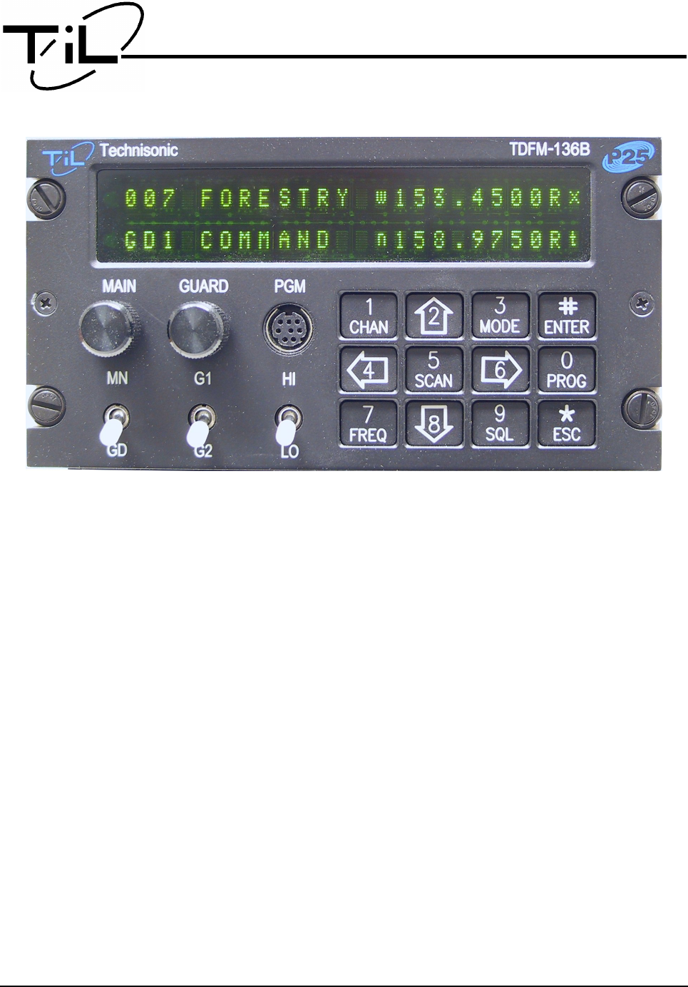
front panel layout of the TDFM-136B is shown in figure 1-1 below.
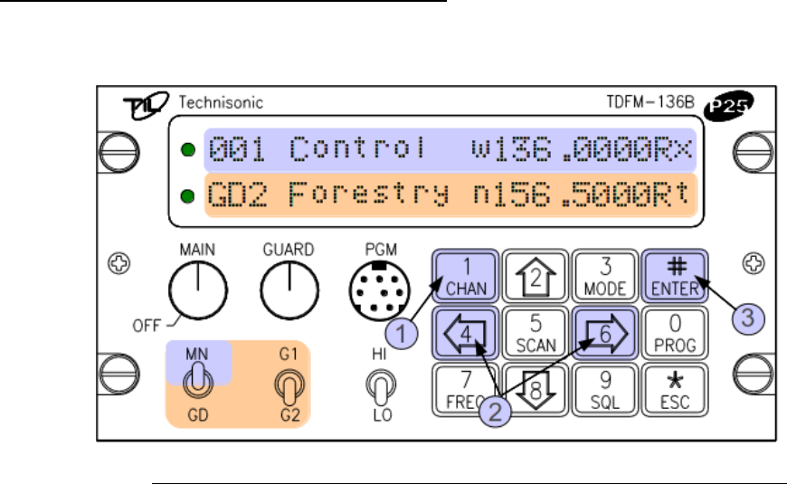
Figure 1-1. The TDFM-136B front panel showing control & display features.
The control and display features are identified as follows:
1. LED channel squelch indicators – light on signal received (top=Main, bottom=Guard).
2. Channel parameter display – two line by 24 character LED display (top=Main, bottom=Guard).
3. Power ON/OFF switch and Main channel volume control (rotary encoder, with p/b switch).
4. Guard channel volume control (rotary encoder with p/b switch) and Squelch defeat.
5. Data port – for use with KVL 3000+ keyloader or TDP-136 Programming software.
6. Main/Guard switch (toggle) – selects active channel (main or guard), for transmit and edit.
7. Guard 1 or 2 switch (toggle) – selects guard memory (GD1 or GD2), for transmit and edit.
8. Transmit Power switch (toggle) – selects transmit power, high (10W) or low (1W).
9. Keypad (12 push buttons) – control other transceiver features (described below).
Technisonic Industries Ltd. 1
08RE399 TDFM-136B Operating Instructions
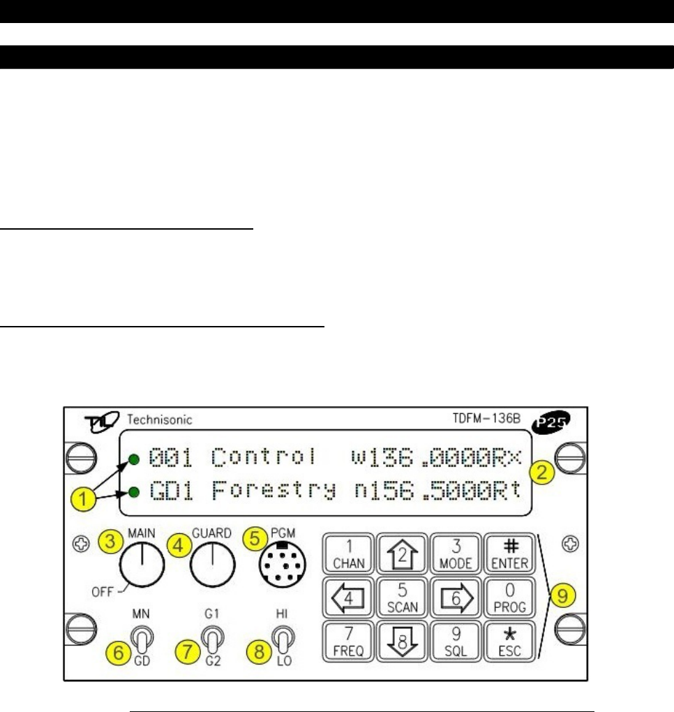
1.1.2 Channel Parameter Display
Figure 1-2 below shows the display of the unit, and identifies the individual parameters
shown for each of the main and guard channels.
Figure 1-2. The TDFM-136B display – unique parameters highlighted.
The parameters that are specific to one channel or are not channel related are identified in figure
1-2 above. Items 1 – 6 fall into this category, they are described as follows:
1. Main channel information is displayed on the top row of the display.
2. Guard channel information is displayed on the bottom row of the display.
3. The Main channel can have up to 230 memory positions (001 to 230), the current active memory
number for the Main channel is shown in the first three characters of the line.
4. The Guard channel can have two memories, GD1 and GD2, the currently active Guard memory
number is shown in the first three lines of the bottom row.
5. Memories for the Main channel can be scanned, when in use, scan information is shown at the
4th character position on the top row.
6. On the bottom row, the 4th character position is used for different purposes: it will indicate the
current command level as well as showing the lock icon () if the keypad access has been
locked out.
7.
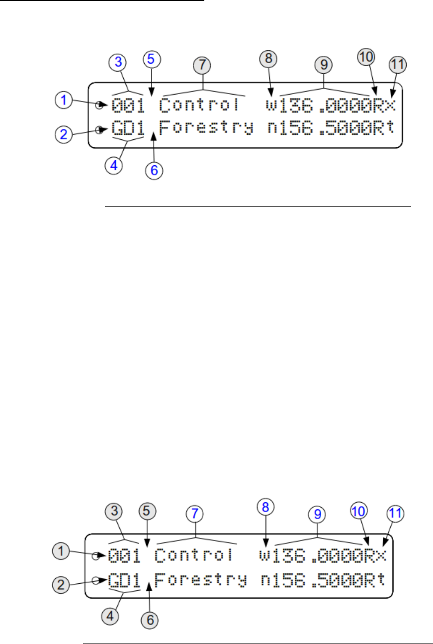
Figure 1-3 below shows the display of the unit, and identifies those parameters that are
common to both main and guard channels.
Figure 1-3. The TDFM-136B display - common channel parameters highlighted.
2 Technisonic Industries Ltd.
TDFM-136B Operating Instructions 08RE399
The common parameters are identified as items 7 through 11 and are as follows:
7. Up to eight characters are available for a text description of the memory.
8. One character position is used to indicate the operating mode:
Analog modes: wide "w"(25kHz.), narrow "n" (12.5kHz.)
Digital mode: project 25 digital "D" (12.5kHz.).
9. Eight characters are used to indicate the frequency in use.
10. One character indicates either Receive or Transmit as: "R" or "T".
11. The final character indicates the current squelch mode:
Analog modes: noise squelch "x", CTCSS tones "t", or DCS codes "c"
Digital modes: monitor "m", NAC only "n", TalkGroup + NAC "g"
1.2 Transceiver Basic Operation
For basic operation of the transceiver the user has the yolk mounted PTT key and memory
up/down keys (if connected) in addition to the controls discussed previously. Basic
operation is discussed in this section.
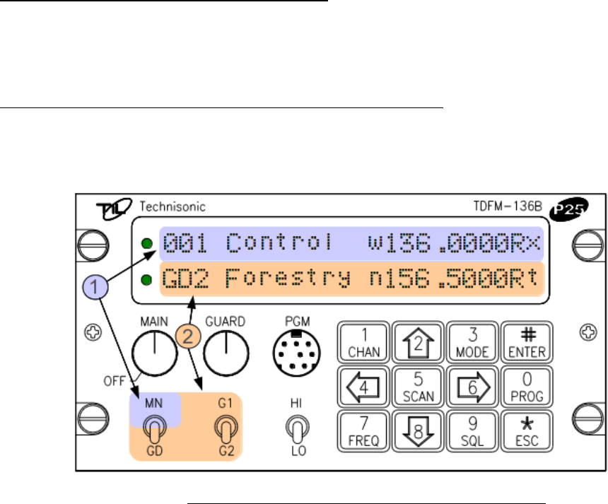
1.2.1 Selecting the Active Channel – Main or Guard
When the user presses 'PTT', the unit will transmit with the parameters of the active channel and
memory, that the user has selected. The method of selecting MAIN or GUARD channel is
described below.
Figure 1-4. The active channel display and control points.
1. The MAIN channel data is shown on the top line of the display, MAIN supports 230
memory positions (001 to 230). The MAIN channel is made the active channel for
transmit and edit by the user placing the MN/GD switch in the MN position. For
selecting the active memory for the MAIN channel, see the following section.
2. When the MN/GD switch is in the GD position then the GUARD channel is active. The
GUARD channel has two fixed memories: GD1 and GD2, the GUARD memory used is
determined by the position of the G1/G2 switch.
Technisonic Industries Ltd. 3
08RE399 TDFM-136B Operating Instructions
1.2.2 Selecting a Main Channel Memory
For the MAIN channel there are 230 possible memory positions to choose from (001 to 230), the
method of selecting a memory for the MAIN channel is described below.
Figure 1-5. Control points for selecting an active memory for the MAIN channel.
There are several ways in which the user can control the active memory for the MAIN channel:
1. Press the 'CHAN' button (1), and then directly enter the three digit memory number.
2. Press and hold either the back arrow (4), or the forward arrow(6) button, and the unit will scroll
through the existing (already programmed) memories.
3. Press the 'ENTER' button (#), and the unit's Main channel will toggle between the current
memory and the designated 'home' memory. If no 'home' memory has been selected, then the
default is channel 1.
Note on scrolling:
•memory numbers that have not been created will be skipped.
•the scroll will wrap both up and down (. . . 230 ↔ 001. . . ).
Example:
The user has memories 001, 002, 004, 010, 024, 100 and 151 programmed into the transceiver.
The MAIN channel is selected, and the active memory is 004. No home memory has been
defined, so the default is 001.
If the back arrow is pressed and held, the MAIN display will scroll to memory 002, then to 001, and
then to 151, the sequence will continue until the user releases the key.
For the Main channel, if the user presses the “ENTER” button, then the MAIN channel will jump to
memory “001”, if the Main memory was something other than “001”, then pressing “ENTER” again
will return to that memory.
4 Technisonic Industries Ltd.
TDFM-136B Operating Instructions 08RE399
1.3 About Commands
The transceiver supports commands to provide more advanced control and configuration
features. A command is simply a key press, or series of key presses, that cause the unit to
perform a function. This section provides an overview of the command architecture.
1.3.1 Command Levels
In order to accommodate all the commands required to provide the necessary operation,
commands have been divided up into levels (abbreviated as 'L1', 'L2' etc). This results in the most
common commands needing the fewest key presses to access.
There are five command levels in all, three of which are available to the operator (Operator
Commands). For each command level up to 10 commands are available: 1-9, and '#'. Note: for
command level 1 (L1) only, the ESC (*) button has an associated function as you cannot go a level
down. The zero (0), and the ESC (*) key are reserved to move between the command levels as
follows:
step up through command levels
step down through command levels
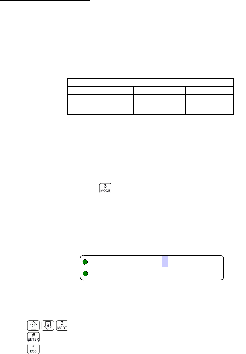
When stepping through command levels, the level is shown as a subscript digit in the 4th character
position on the lower line of the display, see figure. Note that this display position is left blank for
the default level (L1).
Figure 1-6. The Screen showing 'Level 3” in the Command Level Display Position
The Operator Command levels 2 and 3 (L2 & L3) are 'time limited', if the user gets into one of
these command levels and does not enter a command within 5 seconds, the unit automatically
returns to command level 1.
Note that after exiting a L2 or L3 command, the timer is reset to 5 seconds, so if you want to return
to level 1 immediately, you have to press level down key ('ESC' or '*'). This allows you to perform
another command on that level without having to start over from level 1.
In addition to the three command levels available to the operator, the unit can be put into a mode
that allows access to maintenance and supervisor commands. These restricted command levels
(L4 & L5) are to allow authorized personnel to set operating policy for the radio through use of
'Permissions', and perform other maintenance and configuration functions; these are explained
later in the manual.
The restricted command levels (L4 and L5) should NEVER be enabled in flight. Incorrect
use could render the unit non-functional! These levels exist for configuration and
maintenance use only.
Technisonic Industries Ltd. 5

08RE399 TDFM-136B Operating Instructions
1.3.2 Command Types
There are two basic types of commands: inherent, and interactive:
Inherent commands
These are simple 'one-touch' commands, they do not need any further input from the user.
Example: the display brightness control commands (up/down arrows, keys 2 & 8)
Interactive commands
These commands require further input from the user, and they must end as follows:
accept the entry and exit
abandon the entry and exit
Example: the 'Frequency' command requires that the user enter a frequency, before exiting.
1.3.3 Command Groups
The commands can be characterized as belonging to one of three groups:
Operating commands are those which perform a function directly related to the use of the radio.
Edit commands allow the user to Edit the RF channel parameters (frequency, mode etc).
Configuration commands affect how the radio operates, including how other commands work.
1.3.4 Command Reference
Throughout the manual the commands will be referred to by level and number to make it clear what
command is being referenced. The short form used is as follows:
Level - abbreviated as 'L' followed by a number, a dash separator, and a command number.
Examples:
The 'edit frequency' command is: level one, command number 7. So the short form is: L1-7. Since
under normal circumstances the transceiver is in level 1, to access the command simply press '7'.
Level two, command number 3 is shown as: L2-3. To get to this command you must first go to
level 2 (by pressing the '0' key), then enter the command key, '3'.
6 Technisonic Industries Ltd.

TDFM-136B Operating Instructions 08RE399
S E C T I O N 2
TRA NSCE IVER OPE RAT ION
This section describes operating the transceiver including using the command functions to
perform common tasks. This section provides more advanced information about
operating the transceiver, starting with the basics and moving through the more advanced
features.
2.1 Channel Operating Parameters
As described in the previous section the transceiver supports two (2) channels: Main and
Guard. Each of these channels operates using the parameters of the currently selected
memory for that channel.
The Main channel operates using the parameters of the currently active main memory, and
there can be up to 230 memories available to the Main channel. Main memory number 001
must always exist, and is the default Main memory when the unit is shipped.
Similarly the Guard channel operates using the parameters of the currently active Guard
memory. The difference is that the Guard channel supports only two memories: GD1 and
GD2, these may be selected via the front panel G1/G2 switch, both of these memories
must exist and are programmed from the factory.
The parameters for any factory programmed memory may be changed by the user.
2.1.1 Memory Parameters
Each memory has a variety of parameters that may be edited by the user including:
•frequency – 8 characters
•operating mode – 1 character
•squelch mode and squelch mode value – 1 character displayed
•text description – up to 8 characters
•scan list – 1 character
The ability to edit some of these may be restricted under certain operating conditions.
Example: while scan is available for any Main channel memory, the user may not set scan
parameters for either Guard channel, or for 'shadow' channels on the Main channel.
2.2 Editing Channel Operating Parameters
There are two ways to change the operating parameters for the memories used by either
the main or guard channel: edit from the transceiver front panel, or edit using the PC
programming software. This section will describe the first option; PC programming is
discussed in Appendix C.
From the front panel, the user can edit any of the parameters (listed above) for the active
channel using the individual parameter edit functions.
Technisonic Industries Ltd. 7
08RE399 TDFM-136B Operating Instructions
In addition to editing the memory parameters individually, the user can create new
memories (for the main channel only) or edit all the parameters of an existing memory (for
Main or Guard channels).
All edit commands are interactive commands (they expect input from the user), as such, the
line on the display that does not have the parameter to be edited, becomes a prompt line to
guide the user as to the valid keys for that edit.
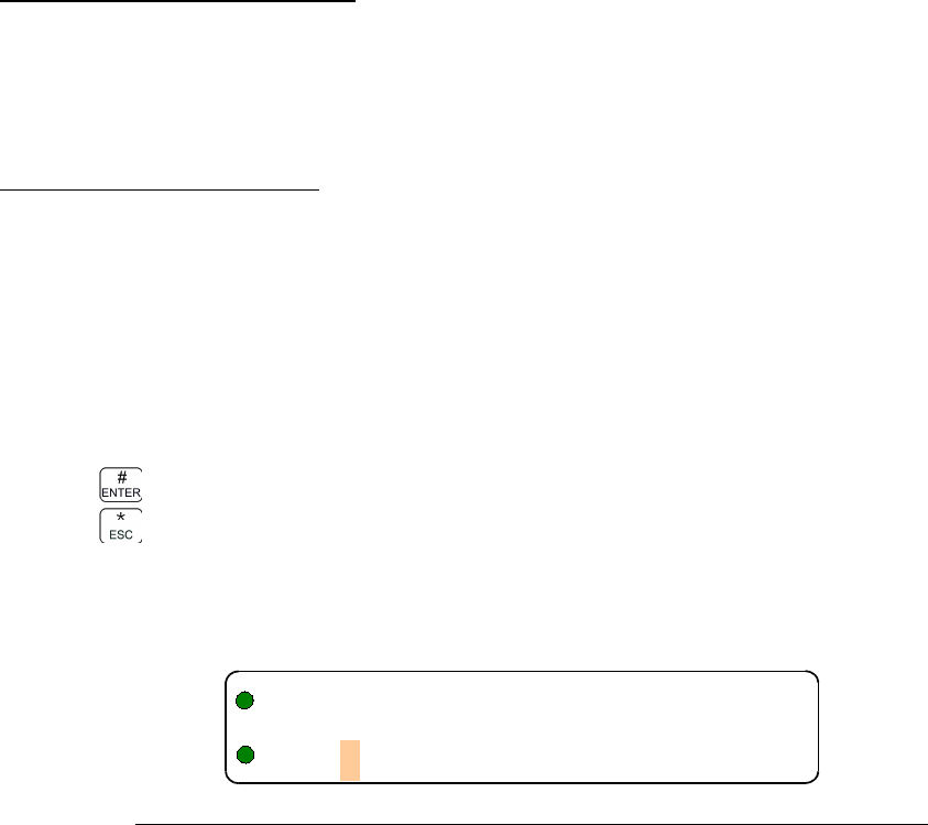
Example: The edit frequency command, figure 2-1 shows the edit frequency screen if the
active memory is 001 on Main. Note that a cursor flashes on the second character in the
frequency field , on the Main display (top row) and that the Guard Display (bottom row)
has been changed to a prompt line . This prompt provides the user with information such
as what command is running, and what keys are valid.
Figure 2-1. The user screen to edit the Main frequency
When the Guard Channel is active, the situation is reversed: the cursor is placed on the
second digit in the frequency field on the Guard line, and the top line becomes the
prompt line.
Figure 2-2. The user screen to edit the Guard frequency
Calling Key.
Some editors simply allow the user to select a set value from a list; in these cases, the key
used to 'call' the editor will also step up through the available choices. This allows the user
to make a selection without having to further navigate the keypad.
Simplex and duplex parameters.
Some of the transceiver parameters are simplex only: they are the same for both transmit
and receive operation. Other parameters are duplex: these may be (but do not have to be)
different for transmit than they are for receive.
Accept and Continue / Accept and Exit
For many edit functions (example Operating Mode), once the user has selected a value,
pressing the key will accept the entry and exit the editor. However, some edit functions
require that the user accept a value before advancing (example Squelch Mode), in these
cases pressing the key will advance to the next point in the editor.
Abandon Edit
In all cases, the key will abandon the edit with no changes made.
8 Technisonic Industries Ltd
!"#$%&'
1
2
1
2
!"#$%&'
2
1
21
TDFM-136B Operating Instructions 08RE399
2.2.1 The Frequency Parameter
The TDFM-136 supports frequencies in the range 136.0000, to 174.0000 MHz. Frequencies in the
analog wide band (25 kHz. channel spacing), the analog narrow band (12.5 kHz. Channel
spacing), and the P25 band (Phase 1 – 12.5 kHz. channel spacing) can be entered at any 2.5 kHz
step. In addition, frequencies can be entered on the frequencies proposed for P25 Phase 2. Note
that this does not mean that the transceiver operates in this mode (6.25 kHz. channel spacing), just
that the transceiver can be tuned to those frequencies; the channel spacing will still be either 25
kHz. or 12.5 kHz. See appendix D for the 6.25 kHz frequencies supported.
Frequency is a simplex/duplex parameter, that is, the unit can transmit and receive on the same
frequency or it may be configured so that the transmit frequency and receive frequency are
different.
Editing Frequencies
The edit frequency command is easily accessible, it is command L1-7. To access this command,
simply press '7', on the front panel keypad. Notice that the key is also marked “FREQ”.
This command allows the user to edit the operating frequency of the selected channel & memory.
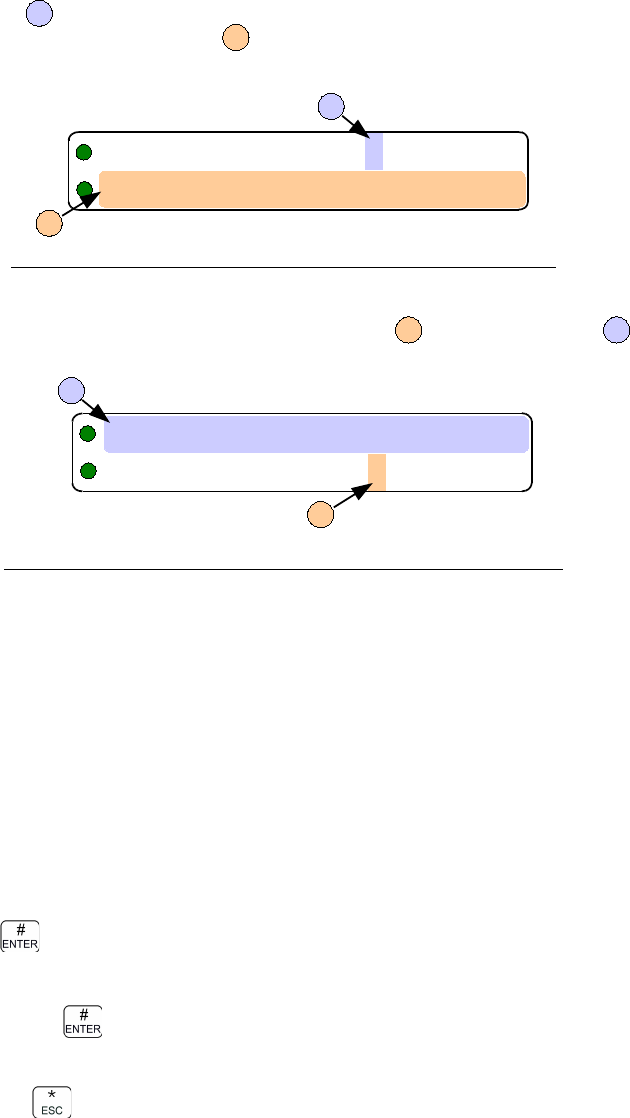
The frequency will be edited in duplex mode: first Receive, then Transmit. Upon start, the cursor
appears at the second character in the Frequency field of the channel to be edited. The edit screen
appears as follows:
Figure 2-3. The user screen to edit the Main frequency for receive
The user may now enter the desired operating frequency as follows:
to decimal mode: enter number, cursor automatically advances
accept the entry and continue
abandon the entry and exit
The editor will not accept a value outside the limits of 136.0000 MHz. to 174.0000 MHz. In addition
frequency supports 2.5 kHz increments, and valid 6.25 kHz channel spacing frequencies in all
Operating modes. See appendix N for valid 6.25 kHz frequencies.
Once the receive parameter is entered, the 2nd last character in the display will switch from “R” to
“T”, the user can now enter the transmit value. Note that the receive value is automatically entered,
so to get simplex operation, simply accept this entry.
Figure 2-4. The user screen to edit the Main frequency for transmit
When complete, accept the entry if it is correct, or escape to exit without saving.
Technisonic Industries Ltd. 9
!"#$%&'
(
!"#$%&'
08RE399 TDFM-136B Operating Instructions
2.2.2 Operating Modes
The operating mode is defined as the RF channel spacing and modulation type used for the
selected channel/memory on the transceiver.
The unit supports three operating modes: Analog wide, analog narrow, and P25 digital. In the
analog wide mode, the radio is operating on 25kHz. channel spacing, on both analog narrow, and
in P25 digital mode, the radio operates with 12.5kHz. channel spacing. In analog modes the
transceiver operates using standard frequency modulation, in the P25 mode the unit uses C4FM.
Table 2-1 shows the available Operating Modes, the bandwidth, and the indicating character used.
Table 2-1 Transceiver Operating Modes
Operating Mode Bandwidth Indicator
Analog Wide 25 kHz 'w'
Analog Narrow 12.5 kHz 'n'
P25 Digital 12.5 kHz 'D'
The user can easily switch between modes on any memory for any channel (ie any Main memory,
and both Guard1 and Guard2). Since the squelch modes are not common across analog and
digital operating modes, if you change between these modes, the Squelch Mode will be affected
(for more on this see 'Squelch Modes' below).
The operating mode is a simplex parameter.
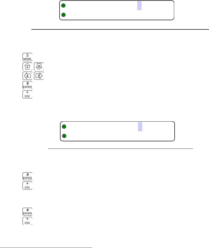
Editing Operating Mode
The edit operating mode command is easily accessible, it is command L1-3. To access this
command, simply press '3', on the front panel keypad. Notice that the key is also marked “MODE”.
This command allows the user to edit the operating mode of the selected channel & memory. Since
operating mode is simplex only, the editor is very simple. Upon start, the cursor appears at the
operating mode character field of the channel to be edited. The edit screen appears as follows:
Figure 2-5. The user screen to edit the Main Operating Mode.
You may now edit the Operating Mode as follows:
step up/down through available operating modes (w, n, D)
accept the entry and exit
abandon the entry and exit
10 Technisonic Industries Ltd
!)*$%&'

TDFM-136B Operating Instructions 08RE399
2.2.3 Squelch Modes
Squelch mode refers to the method employed to defeat squelch and open the receiver. The
transceiver supports a variety of squelch modes for both analog and digital operation, these are
shown in table 2-2 below.
Table 2-2. Receive and Transmit Squelch Modes
Analog Digital
Rx Tx Rx Tx
Noise x CTCSS Tones t Monitor m TalkGroup + NAC g
CTCSS Tones t DCS Codes c NAC Only n ID Call i
DCS Code c Inhibit - TalkGroup + NAC g Inhibit -
Non-Selective Squelch
In analog operating modes (w & n), the Noise squelch is non-selective, that is: if a valid signal of
enough power is present, the squelch will be defeated and the signal received.
Note: Noise squelch is the only squelch parameter that is global, the value needs only to be set
once on any memory and it will apply to all memories on that channel.
For the P25 digital mode (D), the Monitor mode is non-selective: it a P25 digital signal of enough
power is present, the squelch will be defeated and the signal received. There is no level setting.
Note: this does not mean that encrypted signals will be received and decoded in these modes!
Selective Squelch
The other squelch modes are selective: the transmitting system must be operating in the same
squelch mode as the receiving system, and must provide the correct information within that mode.
Scope
Squelch modes are non-orthogonal, that is, they are not the same across differences in Operating
Mode or for receive and transmit operation.
Parameters in Memory
For each memory created there is a default value for each of the squelch modes: the memory
does have a CTCSS tone, a DCS code, a TalkGroup and a NAC assigned, it is just that these
parameters are not used unless the associated squelch mode is chosen.
Since each squelch parameter exists for each memory, and each has a default value, these default
values, like all user editable channel parameters, can be set. In addition, Squelch use may be
restricted according to: which Squelch Modes may be selected for any Operating Mode, which
Squelch Modes may be edited (ie change value), and – in the case of Tones and Codes – which
values are available to be selected. See the Maintenance Level (L4) for appropriate commands.
Description
For signals that are on frequency and not encrypted, the Squelch Modes work as follows:
In Analog Modes:
Noise Squelch, 'x' – analog receive only, non-selective. The receiver will open if there is
enough RF energy on frequency. This is the default analog squelch mode.
CTCSS Tone, 't' – analog receive and transmit, selective. The receiver will open if the signal
received also carries the correct tone. The tones may be the same or different for receive or
transmit on any memory.
DCS Code, 'c' - analog receive and transmit, selective. The receiver will open if the signal
received also carries the correct code. The codes may be the same or different for receive or
transmit on any memory.
Technisonic Industries Ltd. 11
08RE399 TDFM-136B Operating Instructions
In Digital Mode
Monitor Mode 'm' - digital receive only, non-selective. The receiver will open on any valid P25
signal. This is the default digital squelch mode.
Network Access Code (NAC) 'n' – digital receive only, selective. The receiver will open on
any P25 compliant digital signal, having the correct NAC.
Talkgroup + NAC 'g' – digital receive and transmit, selective. The receiver will open on any
P25 compliant digital signal, having the correct NAC, and the correct TalkGroup. For transmit it
indicates that the specified NAC and TalkGroup codes will be transmitted.
ID Call 'i' – digital transmit only, selective. The transmitted signal will carry the ID of a specific
transceiver. Only a radio with that ID programmed as it's Unit Identification (UID) will be able
to receive the signal. Note that the UID can be set via command L5-9.
In Both Analog and Digital Modes
Transmit Disabled '-' – valid for both analog and digital operating modes, transmit only. This
indicates that transmit is disabled for this memory. Pressing PTT will result in a display of
“Transit Disabled” on the screen.
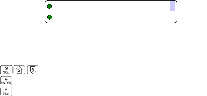
Editing Squelch Modes
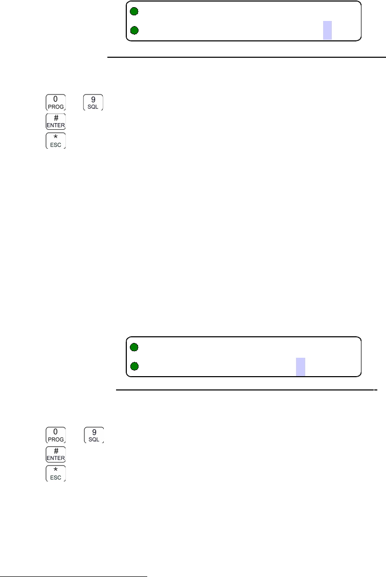
The edit squelch mode command is easily accessible, it is command L1-9. To access this
command, simply press '9', on the front panel keypad. Notice that the key is also marked “SQL”.
This command allows the user to edit the squelch mode of the selected channel & memory. Since
squelch mode is duplex, and the selective squelch options have values that can be edited as well,
this editor has more steps than most others. The general flow of the editor is as follows:
1. Select receive Squelch mode (dependent on operating mode).
2. If Squelch mode has a value then select the value(s)
3. If simplex then done, else repeat for transmit.
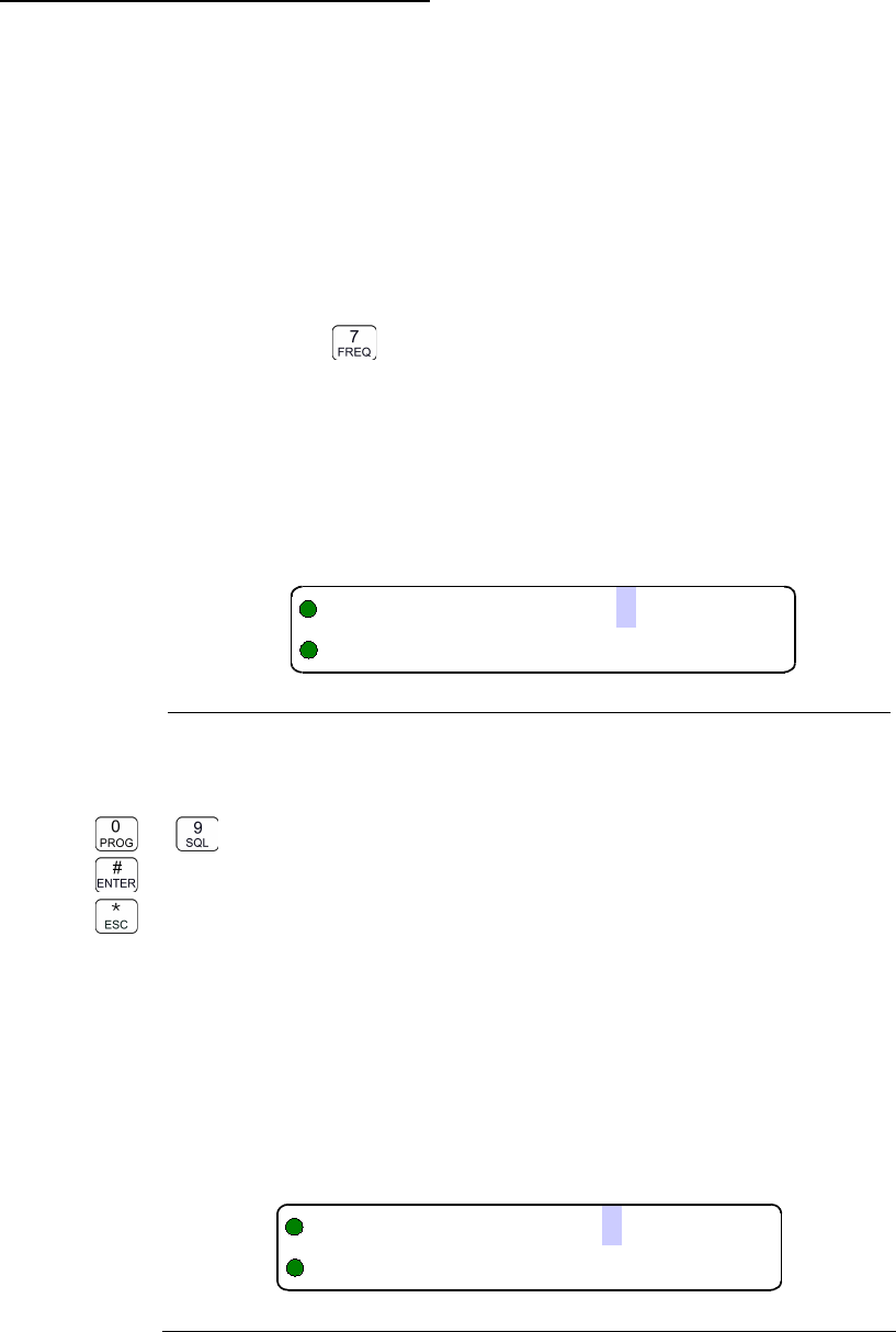
All Squelch mode edits start the same way, the cursor appears at the Squelch mode character field
of the channel to be edited. The edit screen appears as follows:
Figure 2-6. The screen to edit the Main Squelch Mode for receive.
You may now edit the Squelch Mode as follows:
step up/down through available squelch modes.
accept the entry and exit
abandon the entry and exit
Remember that the available squelch modes will be constrained by the operating mode as shown
in table 2-2 above.
12 Technisonic Industries Ltd
+!)*#$%&'
TDFM-136B Operating Instructions 08RE399
Editing analog squelch modes
For analog receive noise squelch the screen to change the value appears as follows:
Figure 2-7. The noise squelch edit screen .
Note that the cursor drops to the bottom row, ready to edit, for noise squelch, the editor operates
as follows:
to decimal mode: enter number, cursor automatically advances
accept the entry and continue
abandon the entry and exit
If editing the receive value, when you press “ENTER” to continue, the editor returns to the first
screen, but the Transmit/Receive indicator character (second last character on the line) has
changed to a “T” to indicate that you are editing for transmit. This allows you to set 'duplex values
for the selective squelch (ie transmit may be different than receive). The screen to select a transmit
squelch mode appears as follows:
Figure 2-8. The screen to edit the Main Squelch Mode for transmit.
The edit keys are the same as for the first screen.
Note that for analog modes “Tx” indicates that no selective squelch will be used, there is no value
associated with the “x” choice for transmit.
For analog CTCSS Tone squelch the user would have to select 't' in the initial screen (in analog
modes only), if so then the editor to change the value would appear as follows:
Figure 2-9. The CTCSS Tone squelch edit screen .
The editor works as follows:
step up/down through available tone choices
accept the entry and continue
abandon the entry and exit
See Appendix B for the table of CTCSS tones supported.
Technisonic Industries Ltd. 13
,-./
(
+!)*#$%&'
(++(/!)*$%&'0
08RE399 TDFM-136B Operating Instructions
As with all the squelch editors, when you press “ENTER” to continue (if editing receive), the editor
returns to the first screen, but the Transmit/Receive indicator character (second last character on
the line) has changed to a “T” to indicate that you are editing for transmit. If you are finishing an
edit of the transmit value, then the values are written to memory and the editor exits.
For analog DCS Code squelch the user would have to select 'c' in the initial screen (in analog
modes only), if so then the editor to change the value would appear as follows:
Figure 2-10. The DCS Code squelch edit screen .
The editor works as follows:
step up/down through available code choices
accept the entry and continue
abandon the entry and exit
See Appendix B for the table of DCS codes supported.
As with all the squelch editors, when you press “ENTER” to continue (if editing receive), the editor
returns to the first screen, but the Transmit/Receive indicator character (second last character on
the line) has changed to a “T” to indicate that you are editing for transmit. If you are finishing an
edit of the transmit value, then the values are written to memory and the editor exits.
Editing digital squelch modes
For digital NAC squelch the user would have to select 'n' in the initial (receive) screen (in digital
mode only), if so then the editor to change the value would appear as follows:
Figure 2-11. The digital NAC squelch edit screen .
The editor works as follows:
to enter number, cursor automatically advances. $=HEX Mode.
accept the entry and continue
abandon the entry and exit
The default edit mode is hexadecimal (HEX), three digits 000 to FFF, the dollar sign “$” is used to
indicate a HEX edit. The edit mode can be changed to decimal using command L3-3. In that case
the range would be 0000 to 4095.
As a squelch mode by itself, NAC exists for receive only so when you press “ENTER” to continue the
editor returns to the first screen, but the Transmit/Receive indicator character (second last
character on the line) has changed to a “T” to indicate that you are editing for transmit.
14 Technisonic Industries Ltd
+/!)*$%&'/1
123"41
51,6/71#
TDFM-136B Operating Instructions 08RE399
For digital TalkGroup+NAC squelch the user would have to select 't' in the initial (receive) screen
(in digital mode only), if so then the editor to change the value would appear as follows:
Figure 2-12. The digital TalkGroup squelch edit screen .
The editor works as follows:
to enter number, cursor automatically advances. $=HEX Mode.
accept the entry and continue
abandon the entry and exit
The default edit mode is hexadecimal (HEX), four digits 0000 to FFFF, the dollar sign “$” is used to
indicate a HEX edit. The edit mode can be changed to decimal using command L3-3. In that case
the range would be 00000 to 65535.
As a squelch mode TalkGroup includes NAC for both receive and transmit so when you press
“ENTER” to continue the editor continues to the NAC editor (shown above). When you exit from
NAC, then if you were editing for receive you would return to the first screen, but the
Transmit/Receive indicator character (second last character on the line) has changed to a “T” to
indicate that you are editing for transmit. If you are finishing an edit of the transmit value, then the
values are written to memory and the editor exits.
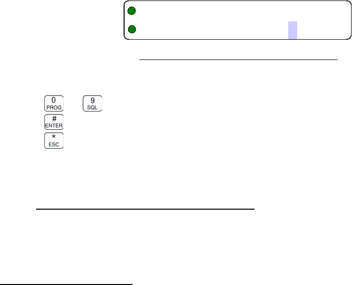
For digital ID Call squelch (available for digital transmit only) the user would have to select 'i' in
the transmit screen, if so then the editor to change the value would appear as follows:
Figure 2-13. The digital ID Call squelch edit screen .
The editor works as follows:
to Decimal mode: enter number, cursor automatically advances.
accept the entry and continue
abandon the entry and exit
The edit mode is decimal only seven digits 0000001 to 9999999.
As a squelch mode, ID Call exists for transmit only so when you press “ENTER” to continue the
values are written to memory and the editor exits.
2.2.4 ID Call Operation
As seen above, the transceiver can be configured, in digital mode, to use ID call as a selective
squelch method, in this mode the transmitting unit sets it's TalkGroup to zero (0), and transmits the
intended Unit ID number (decimal 0 to 9,999,999), upon seeing the '0' talkgroup, the receiver
ignores everything except the ID number.
Of course the receiver will have to be on the correct frequency and in digital mode.
Technisonic Industries Ltd. 15
123"41
51(89/7
123"41
51:%/
08RE399 TDFM-136B Operating Instructions
The TDFM-136 has two distinct RF modules (Main and a dedicated Guard receiver). Unit ID's are
set to default ID's of 1 for Main and 2 for Guard. The Unit ID is a user set number, not a factory ID,
so if they are to be used, then they need to be set. The command to set the Unit ID is command
L5-9, the UID (Main or Guard) to be set is determined by front panel switch positions. The screen
to edit these numbers appears as follows:
Figure 2-14. The Set Unit ID edit screen .
The editor works as follows:
to Decimal mode: enter number, cursor automatically advances.
accept the entry and exit
abandon the entry and exit
The edit mode is decimal only seven digits 0000001 to 9999999.
2.3 Scan and Multi-Mode Operation
The transceiver supports two modes of operation where it is able to receive signals on
more than the displayed main and guard memories. These modes are: scan and multi-
mode operation.
2.3.1 Scan Operation
The radio supports a basic scan mode that operates on the Main channel only. The scan function
allows users to monitor up to 16 channels at a time. All memories must be a member of one, and
only one, scan list; each scan list can hold up to 16 memories. Each memory in a scan list can be
enabled for scan or disabled (see command L2-5).
To scan a particular list: the current Main channel memory must belong to that list, and must have
it's scan enabled. Under these conditions, when you press the scan button (5), the unit will scan.
Example: There are seven (7) memories assigned to scan list three, these are: 5, 6, 13, 15,
23, 34, and 51. Memories 6 and 15 have scan disabled, the rest have scan enabled.
If the user is on channel 6 or 15 and tries to start scan (command L1-5), there will be
an error message: “Error: Non-Scanned Chan” and nothing will happen.
If the user is on any other channel in scan list three, then the five scan-enabled
channels in list three will be scanned.
You can enable or disable scan for the displayed memory (for Main channel only) by using the
command L2-5.
You can affect the scan operational parameters by using command L3-5. This command allows
you to affect the following four (4) parameters:
•Revert Mode
•Reply Timer
•Monitor Timer
•Delay Timer
16 Technisonic Industries Ltd
"#+:;
:;%/

TDFM-136B Operating Instructions 08RE399
Revert Mode. The Revert Mode refers to whether the radio will, when keyed, transmit on
the currently selected memory channel, or on the last contacted memory channel. The radio will
only respond on the last contacted channel for a time determined by the Delay timer setting, once
the timer times-out, then the unit always transmits on the selected channel.
Default: last contacted
Reply Timer. The scan Reply time is the time that the radio will monitor a channel on which RF
was received, after all activity on the channel has ended (Rx or Tx). If there is further receive or
transmit activity on the channel, the timer will reset, and start again once the activity has ended.
When the timer times-out the unit will resume scan. If set to zero (0), the unit will resume scan
immediately upon the end of channel activity.
Range: 0-20s, Default: 3 seconds
Monitor Timer. This is the time that the radio will monitor a channel on which RF was received,
before resuming scanning. Once the timer expires, the unit will break and resume scan, if the value
is set to zero (0) then the unit will monitor the signal as long as it is received.
Range: 1-90s, Default: 10 seconds
Delay Timer. The Delay time is the time that the radio will remain monitoring a channel after
receiving on that channel has ended. If the timer is set to zero, (0), then the unit will resume
scanning immediately after receive activity ends. This is the timer that affects the Revert Mode
'Contacted'.
Range: 0-15s, Default: 5 seconds
2.3.2 Multi-Mode Operation
Multi-mode operation allows mixing of analog and digital operating modes on one frequency. In
effect, this mode allows one memory position to be set up as though it has multiple sets of
parameters associated with it. This manual will refer to this as 'shadow memory' operation: a
'primary' memory can have up to seven 'shadows' for a total of eight sets of operating parameters
(1 primary + 7 shadows).
The user invokes this mode by selecting an existing memory to be a 'primary' and assigning at
least one 'shadow' memory to it, the command to do this is L2-7. Each 'shadow' takes up one
memory position, just like a normal memory.
The shadows have certain restrictions:
•a shadow must have the same frequency as the primary
•a shadow cannot have scan enabled
•a shadow cannot transmit in digital ID call (i) mode
You can mix analog and digital Operating Modes, you can configure different shadows to have
different squelch parameters.
Shadow operation is much like scan in last contacted mode, once a signal has been received, the
user has a set amount of time to key the radio, the unit will transmit with the parameters of the
shadow that decoded the signal: in other words you will respond to the person who called you.
When mixing analog noise squelch with analog selective squelches, the noise squelch shadow will
delay decode for a short time to allow the selective squelch channels time to decode, if none of the
selective squelch channels decode a valid signal, then squelch is broken on the noise squelch
channel.
The radio will operate in Mixed Mode when the Main channel has any memory in the shadow
group selected (ie either Primary or any shadow). The only difference between selections is that if
the user keys the radio, other than to respond to a received transmission, then the radio will
transmit using the displayed parameters.
Technisonic Industries Ltd. 17
08RE399 TDFM-136B Operating Instructions
Primary memories with shadows are identified with a large diamond in the 4th character position:
Figure 2-15. Identifying Graphic for Primary Channel with Shadows
Shadow memories are identified with a small diamond in the 4th character position:
Figure 2-16. Identifying Graphic for Shadow Channel
2.4 Controlling User Access
Whether to restrict operation to correct modes, or to help avoid mis-configuration in the
field, it may be advantageous to control user access to certain features. The transceiver
supports controlling access to features in different ways, these include:
1. Controlling access to command levels.
2. Controlling access to individual commands via command permissions.
3. Controlling access to squelch modes.
4. Controlling editing of specific memories.
5. Controlling display of frequency information.
2.4.1 Control Access to Command Levels
The most basic access control is provided by the built in restriction of access to Maintenance and
Supervisor level commands (L4 and L5 respectively). Maintaining this access security is crucial for
any subsequent access control, as those methods are all accessed via commands on the L4 and
L5 programming levels. Access to these command levels is gained on one of two ways:
Access via Jumper requires that a hardware jumper (shunt) be placed across two pins inside the
transceiver. Obviously the transceiver must be opened on a bench to use this method. See
appendix A for side panel removal instructions and jumper placement.
Access via Jumper and Passwords is the default condition. When configured like this the
transceiver does not need to be opened to access the restricted command levels. There are two
passwords: one for level 4 (Maintenance), and one for level 5 (supervisor).
Passwords are eight characters long and have the full range of characters available for text edit
(see L2-6 for character list reference).
When attempting to enter the Maintenance Level (L4) you will be prompted for a password, upon
correct entry of the L4 password, you will be granted access to that level
When attempting to enter the Supervisor Level (L5) you will be prompted for a password, upon
correct entry of the L5 password, you will be granted access to that level.
If the Supervisor password is entered when attempting to access the Maintenance level, then
access to both Maintenance and Supervisor Levels is granted.
18 Technisonic Industries Ltd
<
="
TDFM-136B Operating Instructions 08RE399
The screen to enter a password upon trying to access L4 or L5 looks like:
Figure 2-17. The screen to enter a password for restricted level access.
Passwords can use any character supported by the standard TDFM-136B text editor, as such the
editing keys are the same:
Step through the available edit groups (A-Z, a-z, 0-9, + extra characters – see table 4.3)
step up/down through the characters in each edit group
move backward/forward through the available characters
accept the entry and exit
abandon the entry and exit
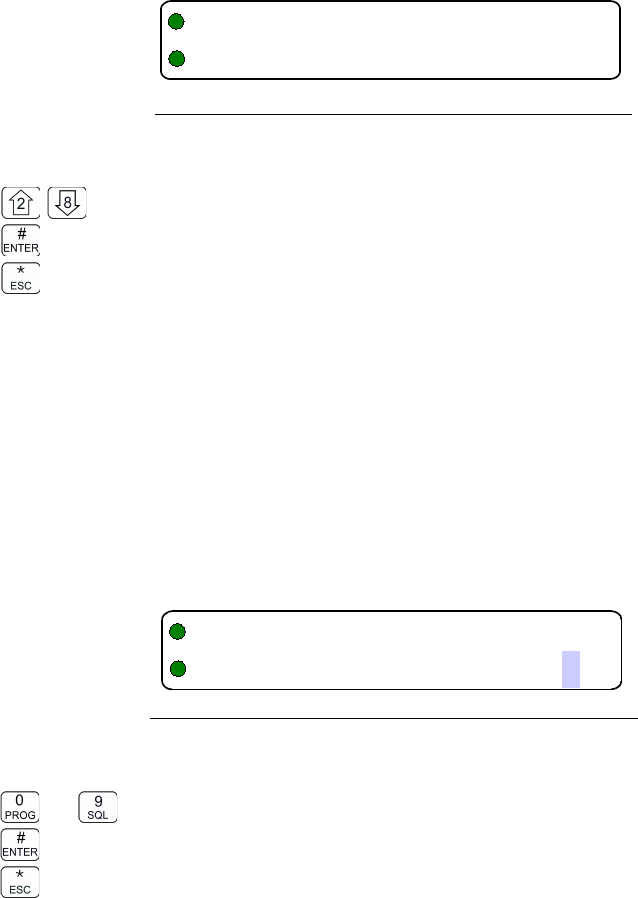
Setting Passwords is done via command L5-7, the command is fixed to edit the Maintenance
password followed by the Supervisor password. Passwords must be eight characters.
Figure 2-18. The screen to set the Maintenance password.
The editor works the same as for entering the password, except that if you are editing the
Maintenance password 'ESC' and 'ENTER' work as follows:
accept the entry and continue to Supervisor
abandon the entry and continue to Supervisor
When entering the Supervisor password screen 'ESC' and 'ENTER' work as in other editors:
accept the entry and exit
abandon the entry and exit
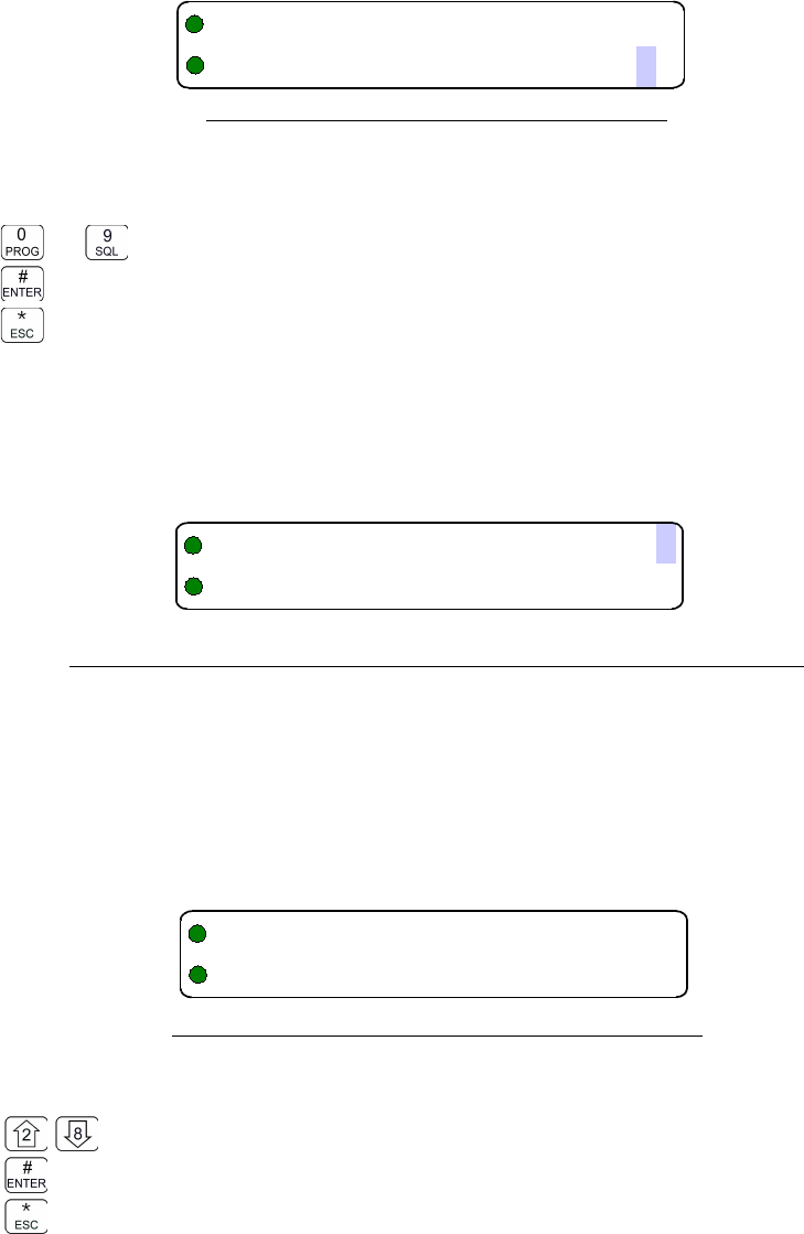
2.4.2 Set Command Permissions
Command permissions allow those responsible for setting policy to select which commands in the
command set will be accessible in the Operator Levels (levels 1, 2, and 3). All the commands in
those three levels are affected EXCEPT: ‘PROG’ (0) and ‘ESC’ (*).
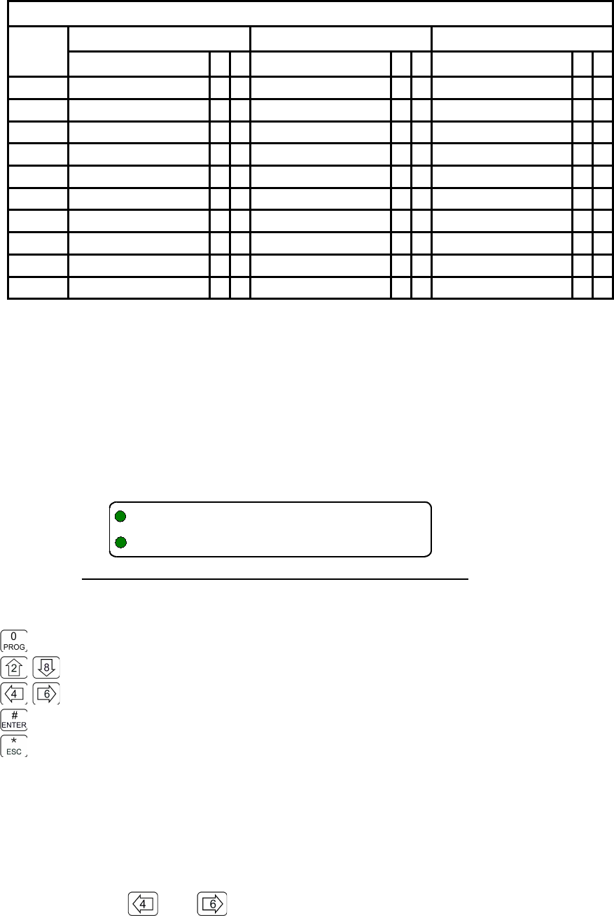
Table 2-3 below indicates all the available user commands, and shows the permission mode as
follows:
●indicates a command that has a distinct permission
●indicates a command is available in Guard, but permission is controlled by Main.
X indicates a command that is NOT available for the channel.
Technisonic Industries Ltd. 19
5/
(!)*>?$%&'#
5/
(!)*>?$%&'#
08RE399 TDFM-136B Operating Instructions
Table 2-3. Permission Applicability by Command and Level
Cmnd
Num
Level 1 Level 2 Level 3
Command M G Command M G Command M G
1 Select Main Memory
●
●
Create/Prog All
●
●
Set Main Boot Memory
●
●
2 Display Brighter
●
●
Copy Guard to Main
●
●
Assign Key by KeyTag
●
●
3 Edit Operating Mode
●
●
Lock Keypad
●
●
Set Edit HEX/Decimal
●
●
4 Scroll Memory Down
●
●
not used X X Show Firmware Version
●
●
5 Scan
●
X Edit Scan List
●
X Set Scan Parameters
●
●
6 Scroll Memory Up
●
●
Edit Text
●
●
Set PTT Timer
●
●
7 Edit Frequency
●
●
Create Shadow
●
X Set sidetone level
●
●
8 Display Dimmer
●
●
Copy Main to Guard
●
●
Communicate with PC
●
●
9 Edit Squelch Mode
●
●
Encryption ON/OFF
●
●
Show Squelch
●
●
ENT Jump to Home Memory
●
X Set Home Memory
●
●
not used X X
The default configuration from the factory has all commands enabled, except L2-2 and L2-8.
Permissions are controlled via three screens that allow you to visually enable or disable each
command for Main and Guard on a level by level basis.
The Set Permissions screen shows the level being affected (L1, L2, or L3), followed by the
command number, and an optional 'g' indicating Guard channel operation for that command (if
applicable). The character directly under each number (or 'g') indicates whether or not the
command may be accessed. If the command is to be accessible (or enabled), then the character is
a is solid round dot, if the command is to be restricted, (or disabled), then the character is an empty
dot or donut. The ‘Set Permissions’ for command level 1 screen appears below:
Figure 2-19. The Screen to Edit the Level 1 Permissions
The user may edit the permissions as follows:
Toggle permission ( @ = enabled, A = disabled
step up/down through Operator Levels
move backward/forward through the available commands
accept the entry and exit
abandon the entry and exit
Note that the cursor will automatically jump to the next valid column, the cursor will wrap. The ‘g’
indicates a separate Guard option; for the commands that support this, the Main and Guard can be
enabled/disabled separately. In addition, some of the commands are either channel agnostic, or
specific to the Main channel only and can thus be invoked for Main even when the radio front panel
switches are in the Guard position.
For example: with the switches in the Guard position the user can still scroll through the Main
memories using the and keys. These types of commands are available in the Guard
mode, but the permissions are determined by the Main permission.
20 Technisonic Industries Ltd
-/1B40BC#B6
@@@@@@@@@@@@@
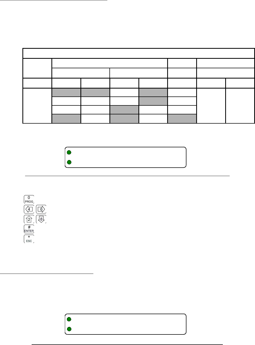
TDFM-136B Operating Instructions 08RE399
2.4.3 Control Access to Squelch Modes
The squelch modes are among the more complicated editing and configuring options; the system
supports an access control scheme that allows you to enable access only to modes that your
organization or specific mission needs.
Command L4-9 is used to restrict user access to squelch modes, editing, and select options, this
can be used to simplify operation and reduces the potential to mis-configure the system. The
access restrictions operate according to the following table:
Table 2-4. Squelch Mode Restrictions
Keys Mode Select Edit Value Select
Analog Digital Analog Analog
← → Rx Tx Rx Tx Mode Tones Codes
↑
↓
NAC Noise Enable /
Disable
individual
Tones.
See table
Appendix C
Enable /
Disable
individual
Codes.
See table
Appendix C
Tone Tone TalkGroup Tone
Code Code ID Call Code
Inhibit Inhbit
Upon start, the display appears as follows:
Figure 2-20. The Screen showing Mode Select restrictions for Analog Receive.
The user may edit the permissions as follows:
Toggle permission ( @ = enabled, A = disabled
move backward/forward through the restriction screens ( ← → select column in table)
step up/down through column entries ( ↑ ↓ select row in table)
accept the entry and exit
abandon the entry and exit
Note you may only restrict editing of a selected value in analog modes.
2.4.4 Control Editing of Memories
In some cases it may be advantageous to set up a memory, and then ensure that the configuration
of that memory cannot be changed by the user. Command 4-4 provides this function. The
currently selected channel memory - as determined by the front panel switch positions -may be
enabled or disabled for editing. The command screen appears as follows:
Figure 2-21. The screen for Enabling/Disabling edit of a specific Memory.
Technisonic Industries Ltd. 21
+ D /+
6B/(@
4"4+3
3/11E
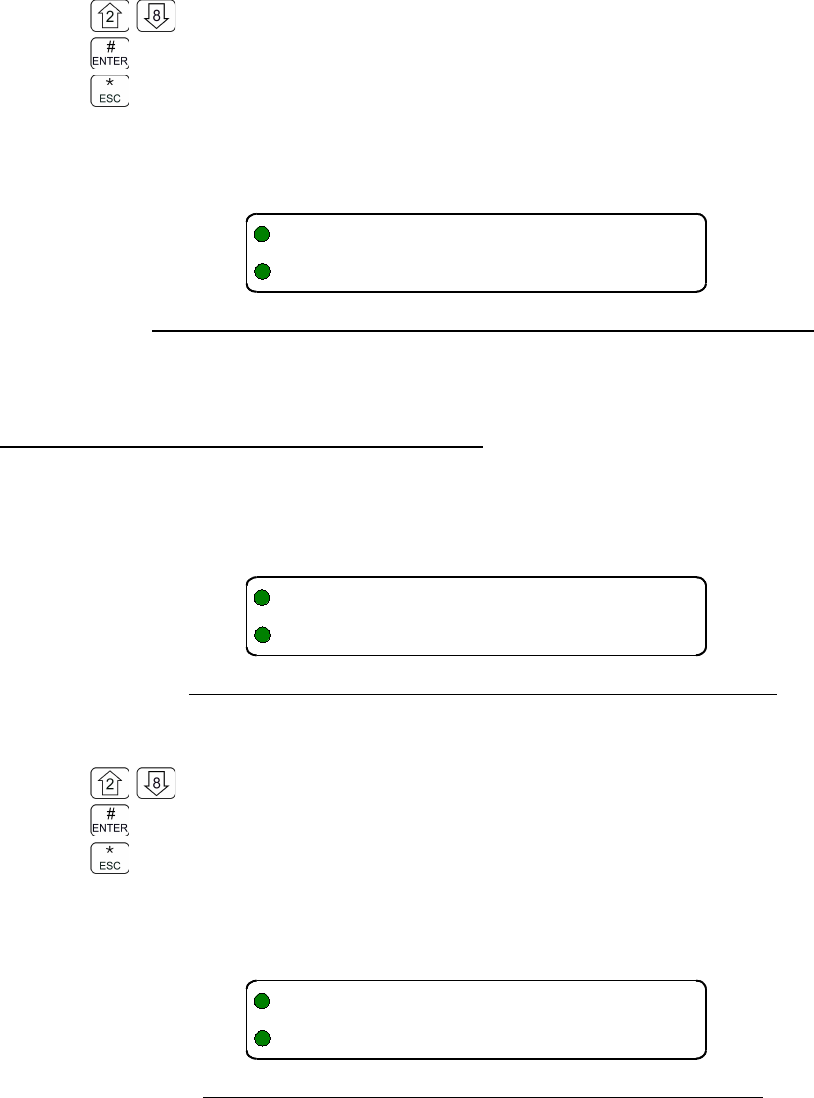
08RE399 TDFM-136B Operating Instructions
The user may change the edit permission for the selected memory as follows:
toggle enable/disable of selected memory
accept the entry and exit
abandon the entry and exit
Note, once a channel has been disabled for editing, any attempt to call a function that would edit a
parameter of the channel would display an error as shown below:
Figure 2-22. The error screen on trying to edit a disabled memory.
Remember that all the channel functions work as normal, they just cannot be changed.
2.4.5 Control Display of Frequency Information
Some agencies may want to restrict access to displayed frequency information for the memories
on Main and/or Guard channels. Command 4-7 provides this function. The currently selected
channel memory - as determined by the front panel switch positions -may be enabled or disabled
for editing. The command screen appears as follows:
Figure 2-23. The Frequency Display Enable/Disable screen.
The user may change the frequency display for the selected memory as follows:
toggle enable/disable displaying frequency for the selected memory
accept the entry and exit
abandon the entry and exit
Note, once a channel has had it's frequency display disabled, you cannot edit that frequency, an
attempt to do so will cause an error as shown below:
Figure 2-24. A memory with frequency display disabled.
Remember that all the channel functions work as normal, it is just that the frequency is not
displayed.
22 Technisonic Industries Ltd
11 13
E
4"0+9
3/119E
11 """"""""3
E

TDFM-136B Operating Instructions 08RE399
2.5 Encrypted Operation
The TDFM-136 supports encrypted operation using both DES OFB and AES encryption
keys for P25 communications. The sequence to use encryption is as follows:
1. Load keys using a KVL keyloader.
2. Assign a KeyTag (name) to a key, defined by its SLN.
3. Assign a key, via the KeyTag to a memory.
4. Enable or disable use of encryption in radio operation.
2.5.1 Loading Encryption Keys
In order to use the encryption feature on the transceiver, you must have encryption keys loaded
into the unit. The keys must be loaded into the unit using a KVL-3000+ keyloader. Of course the
keys must have been created in the KVL first. Operating instructions for the KVL are beyond the
scope of this document, see manufacturer documentation.
Note: The keyloader (KVL) must be connected to the transceiver with the correct cable: ensure
you only use a cable designed for use with the TDFM-136B.
Once you have a KVL with the correct keys loaded, follow this procedure to load and use them in
the transceiver:
1. Connect the KVL to the TDFM-136 via the correct cable.
2. Load the keys following the KVL procedure. The keys will load to the Main or Guard
module as determined by the front panel switches.
3. Once you have loaded one module, you must load the same keys in the same order into
the other module. This is because the Guard operation is split across the two hardware
modules.
2.5.2 Assign KeyTag to Encryption Keys
Once the keys have been loaded, you need to assign a name (referred to here as a KeyTag) to the
key so that they can be manipulated later. Initially, the key will be identified by it's SLN (sometimes
called CKR).
Command L4-8 allows you to set the KeyTag for any of the keys loaded into the radio following this
sequence:
1. Select the key, by SLN, to assign a KeyTag to.
2. Enter the KeyTag
3. Repeat for other SLN's if desired.
Select Key by SLN. The first screen, shown below, allows you to step through the available
keys (by SLN), and shows the encryption algorithm for that key.
Figure 2- 25 . The screen to select the SLN to assign the KeyTag to.
Technisonic Industries Ltd. 23
+ F+-,!>?$%&'
+-,/6-/+
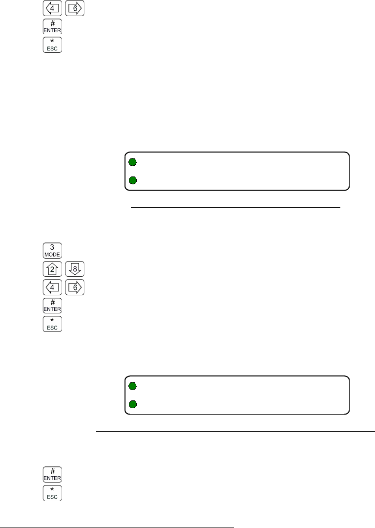
08RE399 TDFM-136B Operating Instructions
You can now select a key via it's SLN to assign a KeyTag to, using the following keys:
move backward/forward through the loaded keys, by SLN
accept the entry and continue
abandon the entry and exit
Create KeyTag for Selected Key. The next screen allows you to create a KeyTag for the
key selected. The system defaults to naming the KeyTags “Key Tag 01”, through “Key Tag 16”, this
screen allows you to change these names to suit your needs.
The KeyTag is 10 characters and is limited to: Upper & lower case alphabetic, the digits 0-9, a
space, and {! “ # $ % & ' ( ) * + , - . /} not including the brace brackets.
The screen to edit the KeyTags looks like this:
Figure 2- 26 . The screen to edit the KeyTag.
The keys for the KeyTag text editor operate as follows:
Step through the available edit groups (A-Z, a-z, 0-9, + extra characters – see table n.n)
step up/down through the characters in each edit group
move backward/forward through the available characters
accept the entry and continue
abandon the entry and continue
Repeat or Exit. The final screen allows you to decide to loop back and repeat the process for
another key or to exit the editor entirely:
Figure 2- 27 . The screen to assign another KeyTag or exit.
The edit keys are:
accept the entry and continue
abandon the entry and exit
2.5.3 Assign Key by KeyTag to Memory
Once the keys have been loaded, and they have been given KeyTags, the user may now assign a
key, using KeyTags, to a memory, provided that the memory is in P25 digital mode.
Command L3-2 allows you to assign a key to a memory in the transceiver following this sequence:
1. Select the memory to assign a Key to.
2. Assign the key via the KeyTag
3. Determine decrypt rules (assigned key or any key)
4. Repeat for other memories if desired.
24 Technisonic Industries Ltd
F(B/F(B
+-,/!)*>?$%&'6G
F(B/F(B
6DFH%I8&I
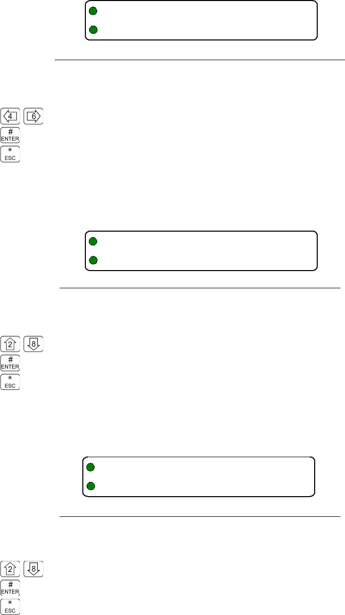
TDFM-136B Operating Instructions 08RE399
Select Memory to Assign a Key to. The first screen, shown below, allows you to step
through the available memories. Note that only main memories have to be scrolled through, the
Guard memories are selectable from the front panel via the MN/GD and G1/G2 toggle switches.
This screen shows selecting a memory for the Main channel:
Figure 2-28. Select the Main memory to assign the key to
The user may select the memory to assign a key to as follows:
move backward/forward through the available memories (Main only)
accept the entry and continue
abandon the entry and exit
Select Key via KeyTag for Memory. The next screen, shown below, allows you to step
through the KeyTags and select one to be assigned to the selected memory.
Figure 2-29. Select the KeyTag to assign to the memory
The user may select the Key, via KeyTag, to assign to the previously selected memory as follows:
step up/down through the available KeyTags.
accept the entry and continue
abandon the entry and continue
Determine Decrypt Rules. The transceiver is capable of decrypting a received signal using
the key that has been assigned to the memory, or by using any key that has been loaded. The next
screen allows the user to make this choice.
Figure 2-30. Select decrypt on Any Key or Assigned Key
Now you can make the 'Any Key' or 'Assigned Key' choice as follows:
toggle the choice: Any Key or Assigned Key
accept the entry and continue
abandon the entry and continue
Technisonic Industries Ltd. 25
"16BFEF(B
3!>?$%&'/
"16BFEF(B
F(B!)*$%&'/F(B
"16BFEF(B
+F/6F
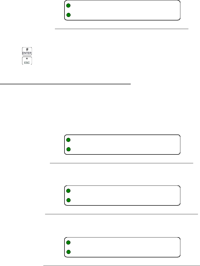
08RE399 TDFM-136B Operating Instructions
Repeat or Exit. The final screen allows you to decide to loop back and repeat the
process for another memory or to exit the editor entirely:
Figure 2-31. The screen to assign another key or exit
The edit keys are:
accept the entry and continue
abandon the entry and exit
2.5.4 Enable/Disable Encrypted Operation
Now that keys have been loaded and assigned to various memories in the transceiver, you can
enable or disable encrypted operation.
On a Digital memory, that has a key assigned to it, the Encryption may be enabled or disabled
using the command L2-9. The command is inherent, there is no edit, either the encryption can be
enabled or it cannot. If you try to enable encryption on an anlog memory (unsupported), you will
see something like:
Figure 2- 32 . The analog memory encryption error screen
On a Digital memory, that does not have a key assigned to it, you will see something like:
Figure 2-33. The error screen for no encryption key assigned
When correctly configured (a key assigned to a Digital memory), you will see something like:
Figure 2-34. The Encryption Enabled for Main memory screen.
26 Technisonic Industries Ltd
"16BFEF(B
6BH%I8&I
;
,6B 9
#3
,+-,6B
11 J413
4
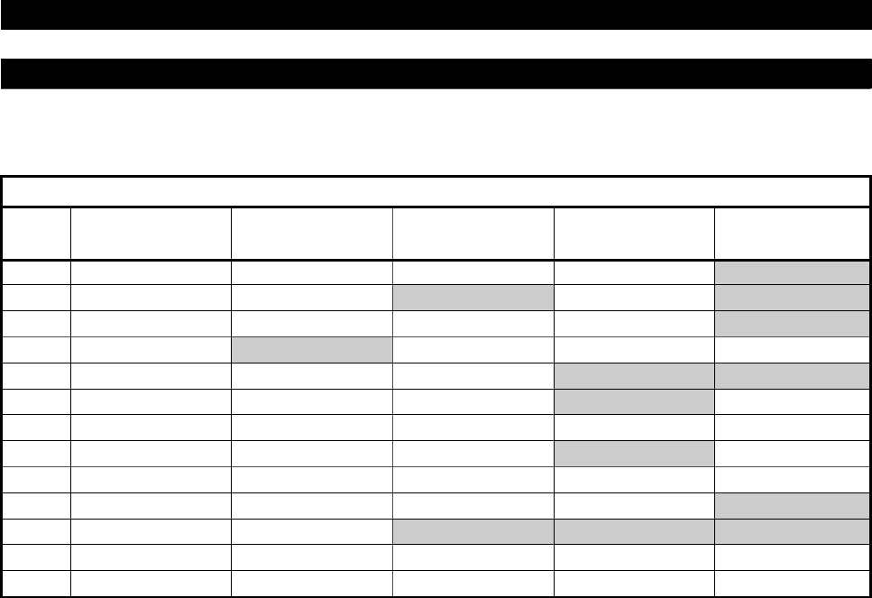
TDFM-136B Operating Instructions 08RE399
SECT ION 3
COMMAND REF EREN CE
This section provides a summary of the commands supported by the equipment, the Table
3-1 below shows a summary the commands divided into command levels.
Table 3-1. Command Level Reference
Key Operator
Level 1
Operator
Level 2
Operator
Level 3
Maintenance
Level 4
Supervisor
Level 5
1 CHAN Select Main Memory Program New Memory Select Boot Memory Select Default Record n/u
2 up Display – Brighter Copy Guard to Main Set Key by KeyTag Select Access Mode n/u
3 MODE Edit Operating Mode Lock Keypad Select Edit Mode Set Cmnd Permissions n/u
4 back Scroll Memory Down n/u Show Code Rev Set Memory Edit Re-Set Data Base
5 SCAN Scan ON/OFF Edit Scan Select Scan Parameters n/u n/u
6 fwd Scroll Memory Up Edit Description Select PTT timer n/u Transparent Mode
7 FREQ Edit Frequency Create Shadow Chan Select Side tone Audio Set Freq Display Edit Passwords
8 down Display – Dimmer Copy Main to Guard PC Communications n/u Run Bootloader
9 SQL Edit Squelch Mode Set Encrypt ON/OFF Show Squelch Values Set SQL Permissions Set Unit ID
0 PROG Go to next level Go to next level Go to next level Go to next level n/u
# ENTER Toggle Home/Current Select Home Memory n/u n/u n/u
* ESC Talk Around Go to Previous level Go to Previous level Go to Previous level Go to Previous level
2+4+6 Emergency Erase Keys
NOTE: n/u indicates command keys that are not currently implemented.
Operator Levels:
Level 1 commands are a mix of operating and editing commands.
Level 2 commands are a mix of operating, editing, and configuration commands.
Level 3 commands are configuration commands.
Restricted Levels:
Level 4 allows qualified personnel to configure access permissions for the radio.
Level 5 allows qualified personnel to change core aspects of the transceiver operation
including erasing and updating the transceiver code.
NOTE: NEVER fly the radio with restricted levels accessible.
These command levels are for maintaining the transceiver only, they are not required for
operation in flight!
Technisonic Industries Ltd. 27
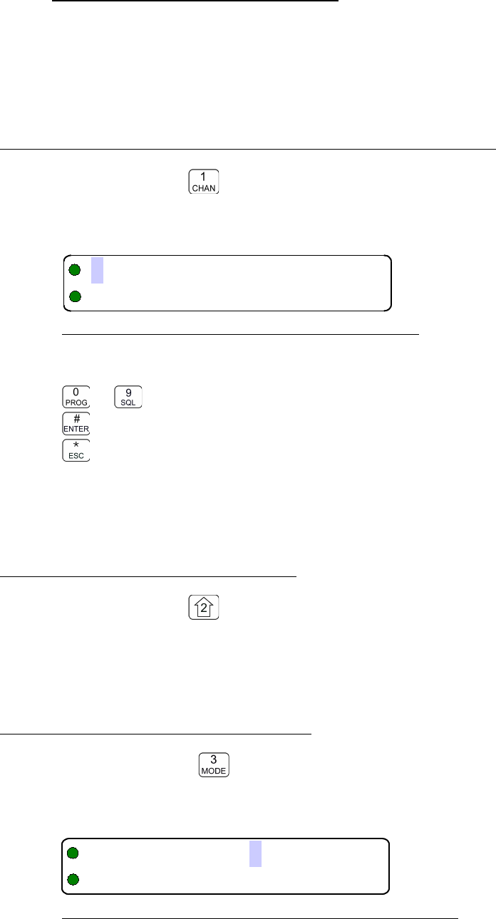
08RE399 TDFM-136B Operating Instructions
3.1 Operator Level 1 Commands
This section lists the commands available to the user in Level 1. The availability of the
commands is subject to the restrictions set by the Permissions policy (see section 2.5).
The commands are listed by increasing number.
3.1.1 Select the Operating Memory for the Main Channel
Level 1 Key Scope: Main only
This command allows you to directly select the memory for the MAIN channel operation, the cursor
will appear at the first digit in the channel number as shown:
Figure 3-1. The User Screen to Enter a Memory Number
Now, select a number from 001 to 230, the cursor wraps. Valid edit keys are:
to Enter digit, cursor automatically advances and wraps
accept the entry and continue
abandon the entry and exit
Note: If the channel number selected is out of range then the cursor will remain until the user
enters a valid number. If there is no information programmed for the channel, the editor will
return to the previously displayed channel.
3.1.2 Increase Display Brightness
Level 1 Key Scope: Main and Guard
Press and hold the up arrow (2) key to increase the brightness of the LED character display, it
stops when the key is released or at maximum, whichever occurs first.
3.1.3 Edit Channel Operating Mode
Level 1 Key Scope: Main and Guard
This command will edit the Operating Mode of the selected channel. Upon selecting this command
the cursor will appear at the MODE position.
Figure 3-2. The User Screen to Edit the Operating Mode
28 Technisonic Industries Ltd
B
!)*$%&'
,3E!"#$%&'
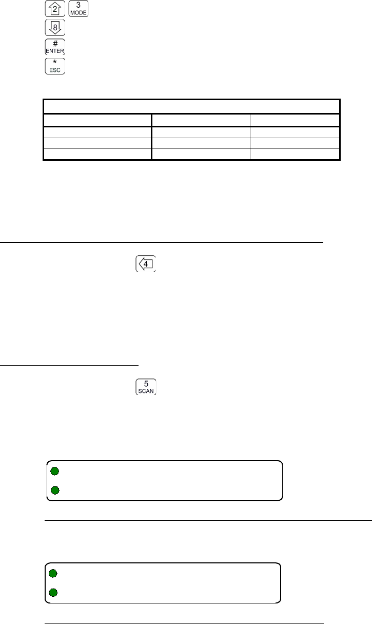
TDFM-136B Operating Instructions 08RE399
Edit Keys
step up through available operating modes (w, n, D)
step down through available operating modes (w, n, D)
accept the entry and exit
abandon the entry and exit
Table 3-2 Transceiver Operating Modes
Operating Mode Bandwidth Indicator
Analog Wide 25 kHz 'w'
Analog Narrow 12.5 kHz 'n'
P25 Digital 12.5 kHz 'D'
Note: If an Operating Mode is selected that is incompatible with the current Squelch Mode, then
the Squelch mode will automatically be changed to one that is acceptable for that
Operating Mode (ie >x' for analog, 'm' for Digital Rx and 'g' for Digital Tx).
3.1.4 Scroll Backwards through Available Memories
Level 1 Key Scope: Main only
Press and hold the back arrow (4) key to scroll the memories for the Main Channel BACK, or
down, through the programmed memories until reaching the lowest memory programmed, it will
then wrap around and restart from the top. Once the user releases the button the displayed
characteristics will be programmed. The scroll speed will increase as the button is held.
3.1.5 Start/Stop Scan
Level 1 Key Scope: Main only
This command allows the user to start and stop Scan operation, the system will scan the channels
that are in the same scan list that the currently displayed Main channel is a member of. Note that
the channels in the scan list must have scan enabled (see command L2-5) to be scanned. If the
scan has not been enabled for the memory, then the following screen appears:
Figure 3-3. Trying to start scan on a Channel with Scan disabled
If the channel has been enabled for scan the user will see the following screen:
Figure 3-4. Start scan on a Channel with Scan enabled
Once scan has started the scan list digit flashes to indicate that the unit is in SCAN mode. Also
note that the key level indicator position has the lock symbol, this indicates that all keypad keys are
disabled except for:
Technisonic Industries Ltd. 29
KB
,"+ D
KB
4
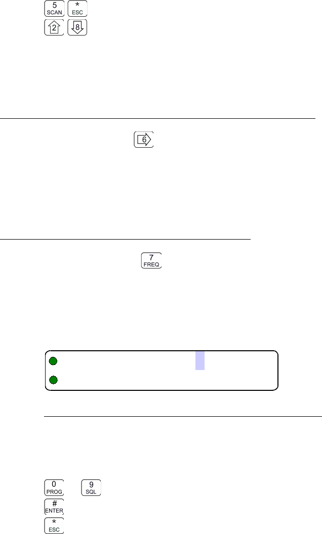
08RE399 TDFM-136B Operating Instructions
Edit Keys
Stop scan
change display brightness
Front panel switch operation is modified as well: operation of MN/GD or G1/G2 will terminate scan
and restore normal operation of keys and switches. The front panel Squelch button is disabled.
The HI/LO power switch is unaffected.
3.1.6 Scroll Forewards through Available Memories
Level 1 Key Scope: Main only
Press and hold the forward arrow (6) key to scroll the Main Channel FOREWARD, or up, through
the programmed memories until reaching the highest memory programmed, it will then wrap
around and restart from the bottom. Once the user releases the button the displayed
characteristics will be programmed. The scroll speed will increase as the button is held.
3.1.7 Edit Channel Operating Frequency
Level 1 Key Scope: Main and Guard
This command allows the user to edit the Operating Frequency of the selected channel. The
frequency will be edited in duplex mode: first Receive, then Transmit. Once the receive parameter
is entered, the 2nd last character in the display will switch from “R” to “T”, the user can now enter
the transmit value. Note that the receive value is automatically entered, so to get simplex
operation, simply accept this entry. The edit screen appears as follows:
Figure 3-5. The User Screen to Edit the Main frequency
Upon start, the cursor appears at the second character in the Frequency field of the channel to be
edited. The user may now enter the desired operating frequency as follows:
Edit Keys
to decimal mode: enter number, cursor automatically advances
accept the entry and continue
abandon the entry and exit
The editor will not accept a value outside the limits of 136.0000 MHz. to 174.0000 MHz. In addition
frequency selection is limited to 2.5 kHz increments and valid 6.25 kHz frequencies in all
Operating modes (see appendix N for valid 6.25kHz frequencies).
30 Technisonic Industries Ltd
!"#$%&'
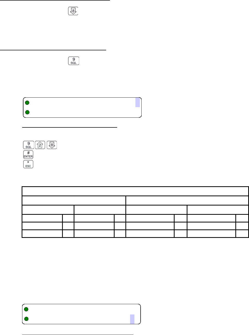
TDFM-136B Operating Instructions 08RE399
3.1.8 Decrease Display Brightness
Level 1 Key Scope: Main and Guard
Press and hold the down arrow (8) key to decrease the brightness of the LED character display, it
stops when the key is released or at minimum, whichever occurs first.
3.1.9 Edit Channel Squelch Mode
Level 1 Key Scope: Main and Guard
Select the Squelch Mode for the active memory (determined by front panel switch positions), and
edit the value if applicable. Note that the scope of the command is subject to restrictions imposed
by the Squelch Permissions – see L4-3. Edit Squelch is a duplex command: Receive followed by
Transmit. At start the cursor appears at the Squelch Mode indicator position as follows:
Figure 3-6 . Editing the Squelch Mode
Edit Keys
step up/down through available squelch modes.
accept the entry and exit
abandon the entry and exit
The available options are constrained by the operating mode as per table 3-3.
Table 3-3. Receive and Transmit Squelch Modes
Analog
Digital
Rx
Tx
Rx
Tx
Noise CTCSS Tones Monitor 3TalkGroup + NAC B
CTCSS Tones DCS Codes NAC Only ID Call
DCS Code Inhibit "TalkGroup + NAC BInhibit "
Once the Squelch Mode has been selected, if applicable, the user will be allowed to edit the value
of the selected mode (subject to restrictions imposed by the Squelch Permissions – see L4-3).
Analog - Noise Squelch Value
Scope: receive only, range 0-16 ($0-$F)
If Noise (Rx) is chosen, the prompt line will display the current value for noise squelch level and
place the cursor on the first digit available for the user to edit:
Figure 3-7 . Editing the Noise Squelch Value
Technisonic Industries Ltd. 31
+!)*#$%&'
,-./
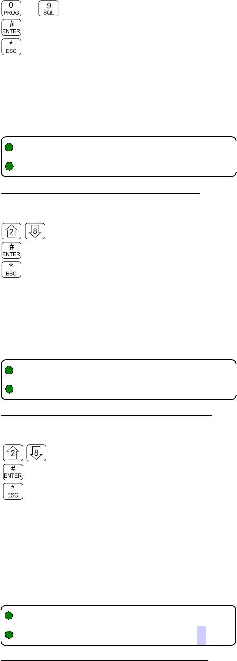
08RE399 TDFM-136B Operating Instructions
Edit Keys
to decimal mode: enter number, cursor automatically advances
accept the entry and continue
abandon the entry and exit
Analog - CTCSS Tone
Scope: receive & transmit, 42 tones (see Appendix B )
If CTCSS Tones are chosen, the prompt line will display the current value for that tone:
Figure 3-8 . Selecting the CTCSS Tone Value
Edit Keys
step up/down through available CTCSS tones
accept the entry and: continue if Rx, exit if Tx
abandon the entry and exit
Edit Analog - DCS Code
Scope: receive & transmit, 83 codes (see Appendix B )
If DCS Codes are chosen, the prompt line will display the current value for that code:
Figure 3-9 . Selecting the DCS Code Value
Edit Keys
step up/down through available CTCSS tones
accept the entry and: continue if Rx, exit if Tx
abandon the entry and exit
Edit P25 Digital - Talkgroup Value
Scope: receive and transmit, range 0-65535 ($0000-$FFFF)
If the P25 TalkGroup was chosen the, the prompt line will display the current TalkGroup value, the
cursor will be on the first digit:
Figure 3-10 . Editing the P25 TalkGroup Value
32 Technisonic Industries Ltd
2
(++(!)*$%&'/0
2
(++!)*$%&'/1
2B
51(89/
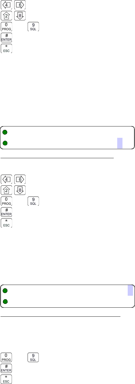
TDFM-136B Operating Instructions 08RE399
Edit Keys
hex edit: move cursor backward/forward through the digits
hex edit: step up/down through the hex digits (0-9, A-F)
to decimal edit: enter number, cursor automatically advances
accept the entry and continue to Edit NAC
abandon the entry and exit
Note: If P25 Talkgroup was chosen, the editor will drop into Edit NAC upon accepting the
Talkgroup value.
Edit P25 Digital - NAC Value
Scope: receive and transmit, range 0-4095 ($000-$FFF)
If the P25 NAC was chosen (or after entering the P25 TalkGroup) the prompt line will display the
current NAC value, with the cursor on the first digit:
Figure 3-11. Editing the P25 NAC Value
Edit Keys
hex edit: move cursor backward/forward through the digits
hex edit: step up/down through the hex digits (0-9, A-F)
to decimal mode: enter number, cursor automatically advances
accept the entry and: continue if Rx, exit if Tx
abandon the entry and exit
Edit P25 Digital - ID Call Value
Scope: transmit only, range 0-9,999,999
If the P25 ID Call was chosen, the prompt line will display the current ID Call value. This
parameter may only be edited in decimal, as follows:
Figure 3-12. Editing the P25 ID Call Value
This transmit only mode allows the user to try to contact a specific radio by transmitting that radio's
user ID. If no radio has that ID then this will fail.
Edit Keys
to decimal mode: enter number, cursor automatically advances
accept the entry and exit
abandon the entry and exit
Technisonic Industries Ltd. 33
2B
51,6/
2(
51:%/
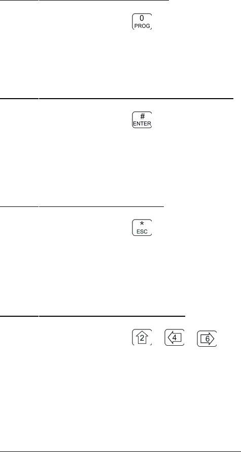
08RE399 TDFM-136B Operating Instructions
3.1.10 Command Level Up
Level 1 Key Scope: Main and Guard
This key selects the next HIGHER Command Level, the Command Level is indicated by a
subscript digit in the 4th character position on the lower row of the display.
3.1.11 Toggle memory: current/home
Level 1 Key Scope: Main only
This key toggles the main channel display between whatever memory is currently selected, and the
designated 'home' memory. If no memory has been selected as 'home' then the unit defaults to
memory '001'.
3.1.12 Toggle Talk Around
Level 1 Key Scope: Main and Guard
Talk around is the name given to the function that allows you to temporarily set a duplex memory to
use the receive parameters for transmit. Simplex channels are, of course, unaffected as the
receive and transmit parameters are already the same.
3.1.13 Erase Encryption Keys
Level 1 Key + + Scope: Main and Guard
Press all three keys at the same time to bring up a screen that allows you to erase all the
encryption keys in the transceiver. This command is irreversible. You must re-load keys with a
key-loader in order to restore keys and hence encryption functionality.
3.2 Operator Level 2 Commands
Access the Operator Level 2 Commands by pressing the “PROG” key from the
Operator Level 1 once. The Menu Level is indicated in the 4th character position on the
lower row of the display, this will indicate a subscript “2”.
Note: the system is time limited in command levels above level 1. The system will
automatically return to level 1 if a command has not been selected in five (5)
seconds!
The Operator Command Level 2 maps the keys to provide a new set of functions for the
operator as shown in Table 3-1. Details of command operation is given below.
34 Technisonic Industries Ltd

TDFM-136B Operating Instructions 08RE399
3.2.1 Create/Edit All Channel Information
Level 2 Key Scope: Main and (Guard)
This command allows the user to create a new memory position (for Main channel only) or to edit
all the parameters of an existing memory position (Main or Guard channels).
The editor steps through the channel parameters in sequence from left to right across the screen.
The edit functions here match those used to edit an individual parameter; however, in this case
selecting the ENTER key accepts the data and proceeds to the next step, rather than exiting. Only
after the last step does selecting ENTER save the data and exit. The ESC key will abandon the
entire edit session at any point without changing an existing channel or creating a new one.
accept the entry and continue – exit only after all edits completed.
abandon the entry and exit
If editing a Guard memory (G1 or G2) then proceed to L2-1.3 as the memory for the Guard channel
is determined by front panel switches only, and scan is not supported for Guard.
L2-1.1. Entering a Memory Number (refer to L1-1 for details)
When the Create/Edit All command is selected, the first step is to enter the number of the memory
position that you wish to Create or Edit, for Main Channel memories, the valid range is (001 to
230).
Once a number has been entered, the system checks to see if the memory location has already
been programmed, if so, then the existing data will be loaded; if the location has NOT been
previously programmed then the default template data will be loaded. In each case the user can
edit the channel parameters in the same way as shown in the following steps.
L2-1.2. Enter a Scan List & Enabling/Disabling Scan (refer to L2-5 for details)
After entering a MEMORY number the cursor will move to the fourth (4th) position on the top line,
the default scan list is shown in subscript. If there is a bar over top of the character, this indicates
that scan is disabled for this memory, if there is no bar, then scan has been enabled. The 'PROG'
key (key 0 ) toggles the scan enabled/disabled state.
L2-1.3. Enter a Text Description (refer to L2-6 for details)
After SCAN, the cursor advances to the first position in the eight (8) character text description field,
the user may now edit the existing text as desired. The editor allows you to select all upper and
lower (A-Z, a-z) case alphabetic characters, the numbers from zero to nine (0-9), and a selection of
extra characters including the space.
L2-1.4. Enter an Operating Mode (refer to L1-3 for details)
After TEXT, the cursor advances on the one (1) character Operating Mode (Mode) field, this single
character represents the operation of the radio: analog wide, analog narrow, or digital.
Technisonic Industries Ltd. 35

08RE399 TDFM-136B Operating Instructions
L2-1.5. Enter a Frequency (refer to L1-7 for details)
After MODE, the cursor advances to the frequency parameter field, this is a seven (7) digit decimal
parameter, though the first digit is always one so the user cannot edit that digit. The frequency
parameter may be edited to any number between 136.0000 and 174.0000 in 2.5 kHz. steps. (ie
150.0025 is valid, 150.0046 is not).
This is a duplex parameter, that is, the user has a chance to edit both the receive value followed by
the transmit value. Once the receive value has been accepted, pressing 'ENTER' again will accept
the same value for transmit. If you wish to have a different value for transmit, then enter it now,
otherwise accept the value for simplex.
L2-1.6. Enter the Squelch Parameters (refer to L1-9 for details)
After FREQUENCY, the cursor advances to the Squelch Mode field. A single character field shows
the Squelch Mode selected. This is a duplex parameter so a different mode can be chosen for
transmit than was chosen for receive. Note that the modes available will be restricted by the
Operating Mode (ie the modes available are different for analog and digital operation).
Once the user is finished and selects ‘ENTER’ then the newly edited channel parameters are
selected and displayed for the appropriate channel. This may take a moment as the information is
programmed into the appropriate RF module at this time as well.
3.2.2 Copy Guard to Main
Level 2 Key Scope: Main only
Copy the currently displayed Guard information UP to the Main channel. This is irreversible, so be
sure you wish to do this. As a safety precaution this command is disabled from the factory. (see
Command Permissions L4-2).
3.2.3 Lock Keypad
Level 2 Key Scope: Main and Guard
This command locks the keypad to prevent accidental change to parameters of the radio
unbeknownst to the operator. This will disable all keyboard functions (except keyboard unlock and
display luminance).
Edit Keys
Lock the keypad, display 'locked' until key release.
Unlock the keypad (after 2 seconds), display 'unlocked' until key release.
3.2.4 L2-4 not used.
Level 2 Key Scope: Command unused.
3.2.5 Edit Scan List & Enable/Disable Scan
Level 2 Key Scope: Main only
This command allows the user to select which of the SCAN LISTs - if any - that the selected
36 Technisonic Industries Ltd
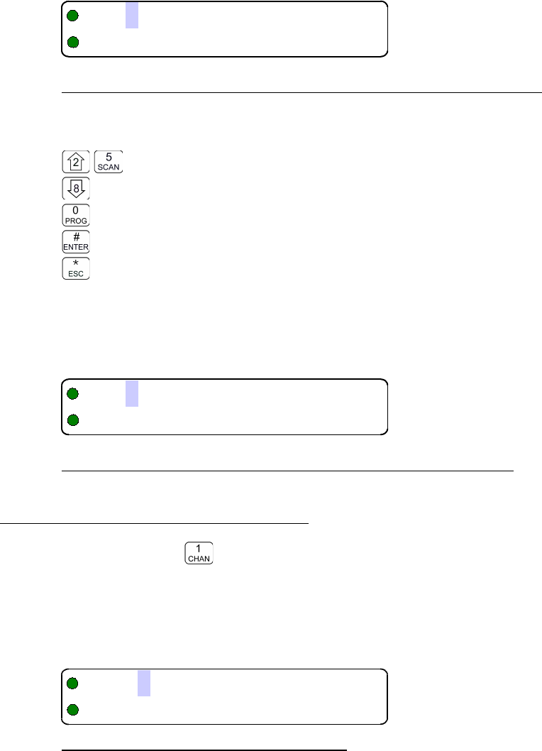
TDFM-136B Operating Instructions 08RE399
channel is included in. The memory must be a member of one of the fifteen (15) scan lists that are
supported. In addition, it allows the user to select whether or not the scan is enabled for the current
memory.
The cursor will move to the fourth (4th) position on the top line, the default scan list is shown in
subscript. If there is a bar over top of the character, this indicates that scan is disabled for this
memory, if there is no bar, then scan has been enabled.
Figure 3-13. The Screen to Enter a Scan List or Enable/Disable Scan
Edit Keys
step up through available scan lists
step down through available scan lists
toggle the scan enable / disable (bar = disabled)
accept the entry and exit
abandon the entry and exit
Note: If a scan list is full, it will NOT appear in the list. This includes the default list, if this
happens, the unit will display the next higher available list, this will stop at list 15 and
then loop back to list 1.
Figure 3-14. The Screen Showing Scan Enabled for this Memory
3.2.6 Edit Memory Text Description
Level 2 Key Scope: Main and Guard
This command allows the user to edit the text description for the selected channel. There are four
groups of characters that may be used; upper case (A-Z), lower case (a-z), numbers (0-9), and 16
extra characters (shown in table 3-4 below). The user can change character groups at any time
and as many times as desired during a description edit session.
Figure 3-15. Editing the Text Description
Technisonic Industries Ltd. 37
L
GM+ !)*$%&'
K
GM+ !)*$%&'
4
(!)*>?$%&'6G
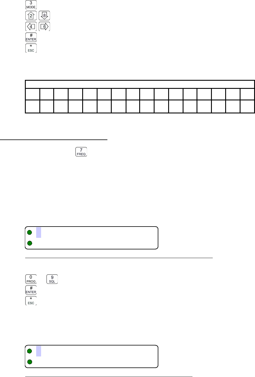
08RE399 TDFM-136B Operating Instructions
Edit Keys
step through the four available edit groups (A-Z, a-z, 0-9, extra characters (see table 3.4)
step up/down through the characters in each edit group
move backward/forward through the available characters
accept the entry and exit
abandon the entry and exit
Note that the up/down arrow keys are scroll enabled, that is, if you hold them you will scroll through
the character set rather than having to press each time you want to advance.
Table 3-4. Extra Characters for Text Edit
1 2 3 4 5 6 7 8 9 10 11 12 13 14 15 16
N O %7 P Q R ! ' & S $ " M
Note: the first character in the table is a blank space.
3.2.7 Create Shadow Memory
Level 2 Key Scope: Main only
This command allows the user to create a shadow of an existing memory on the Main channel. To
do so there are two basic steps: select an existing memory as the Primary memory, and then
create a shadow memory of the primary.
L2-7.1. Selecting a Primary Memory to Base the Shadow On
First, pick an existing memory to act as the primary, up to seven other memories can be linked to
this one as 'shadows'.
Figure 3-16. Entering a Primary Memory for the Shadow Channel
Edit Keys
to decimal mode: enter number, cursor automatically advances
accept the entry and continue
abandon the entry and exit
L2-7.2. Create a Shadow of the Primary Memory
To create a shadow memory, start by entering a number for the shadow memory:
Figure 3-17. Entering a Shadow Channel Memory Number
38 Technisonic Industries Ltd
533
,3E!"#$%&'
+D3
,3E!"#$%&'
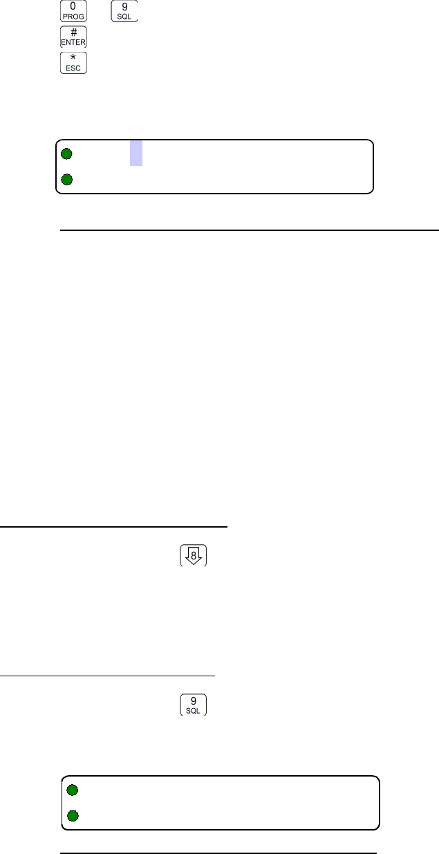
TDFM-136B Operating Instructions 08RE399
Enter a number for the shadow memory, do not select a number already in use:
Edit Keys
to decimal mode: enter number, cursor automatically advances
accept the entry and continue
abandon the entry and exit
Assume that the user entered '061' as the desired shadow channel number. The radio will now
display the data from the chosen Primary channel:
Figure 3-18. Edit the Shadow Memory Parameter - Text
The user may now edit those data fields that are valid for a shadow channel. These are:
•Text Description
•Operating Mode
•Squelch Mode and associated value
The editor functions and keys are the same as for any of the independent editor operation, the
difference, as with Create New / Program All (L2-1), is that the ENTER key will advance to the
next editor until all valid fields have been entered, then the ENTER key accepts and exits.
Note that there are some parameters that cannot be edited:
•Frequency is fixed to that of the Primary channel
•Shadow channels cannot be scanned.
•Shadow channels cannot use the Digital Squelch Mode IDcall (i).
3.2.8 Copy Main to Guard
Level 2 Key Scope: Main and Guard
Copy the currently displayed Main information DOWN to the selected Guard channel. This is
irreversible, so be sure you wish to do this. As a safety precaution this command is disabled from
the factory. (see Command Permissions L4-2).
3.2.9 Encryption ON/OFF
Level 2 Key Scope: Main and Guard
This command allows the user to turn Encryption ON or OFF providing that the current channel is a
digital channel with an encryption key assigned to it. If so, you will see something like:
Figure 3-19. The Encryption Enabled for Main.
Technisonic Industries Ltd. 39
DB
(!)*>?$%&'6G
11 J413
4
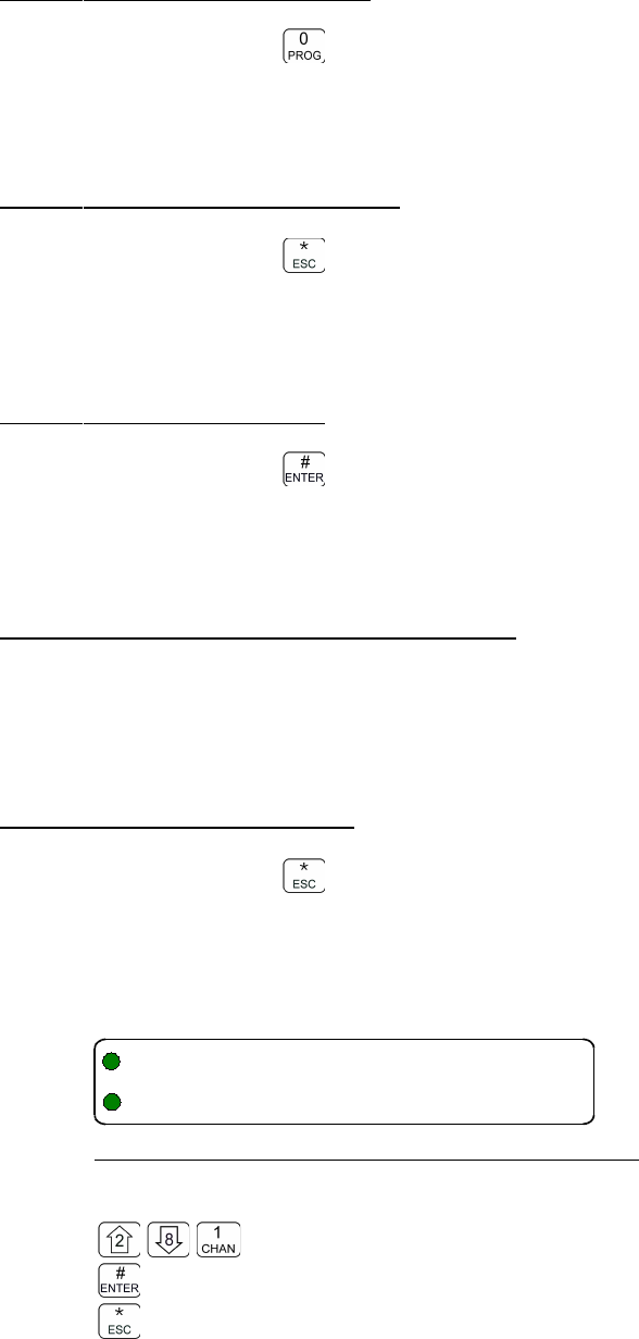
08RE399 TDFM-136B Operating Instructions
3.2.10 Command Level Up
Level 2 Key Scope: Main and Guard
This key selects the next HIGHER Command Level, the Command Level is indicated by a
subscript digit in the 4th character position on the lower row of the display.
3.2.11 Command Level Down
Level 2 Key Scope: Main only
This key selects the next LOWER Command Level, the command Level is indicated by a subscript
digit in the 4th character position on the lower row of the display.
3.2.12 L2–#. Not Used.
Level 2 Key Scope: Main only
3.3 Operator Level 3 Commands
The Level 3 commands are configuration commands that allow the operator to configure
many of the default parameters of the radio, in addition, level 3 has the PC upload and
download commands.
3.3.1 Select Boot Channel
Level 3 Key Scope: Main only
Select which memory that will be used for the Main Channel when the unit is turned on: the last
Selected memory, the last Programmed memory or the Home memory .
The default is: last Selected memory.
Figure 3-20. Selecting Main Channel Boot Memory
Edit Keys
step up/down through available boot memory choices
accept the entry and exit
abandon the entry and exit
40 Technisonic Industries Ltd
"+T3
TU/-+
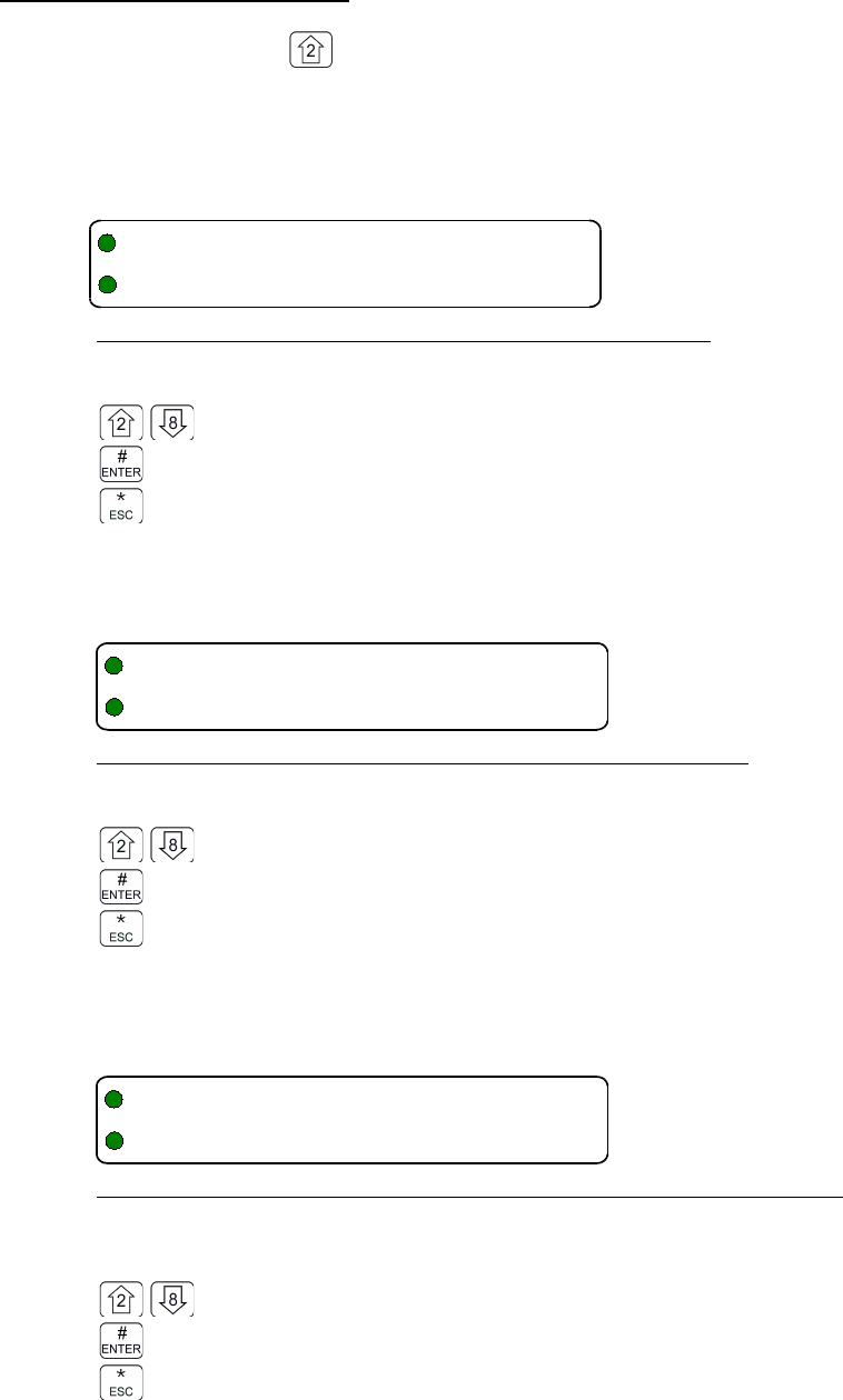
TDFM-136B Operating Instructions 08RE399
3.3.2 Assign Key by KeyTag
Level 3 Key Scope: Main only
This command allows the user to select a memory, and then assign a key, via the KeyTag, to that
memory.
First, step through available memories, and select one to assign a key to.
Figure 3-21. Selecting the Memory to Assign the Key to
Edit Keys
step up/down through available memories (Main only)
accept the entry and exit
abandon the entry and exit
Once a memory has been selected, then step through the available KeyTags and pick one to
assign to the selected memory.
Figure 3-22. Selecting the KeyTag to Assign to the Memory
Edit Keys
step up/down through available keytags.
accept the entry and exit
abandon the entry and exit
After assigning the key, set how the decrypt function is applied to receiving on this memory: by only
decrypting signals encrypted with the assigned key, or by decrypting if the received signal was
encrypted using any key currently loaded into the radio.
Figure 3-23. Selecting the decrypt option: Any Key or Assigned Key
Edit Keys
toggle Receive Key Option: Any Key / Selected Key.
accept the entry and exit
abandon the entry and exit
Technisonic Industries Ltd. 41
"16BFEF(B
3!>?$%&'/
"16BFEF(B
F(B!)*$%&'/F(B
"16BFEF(B
+F/6F
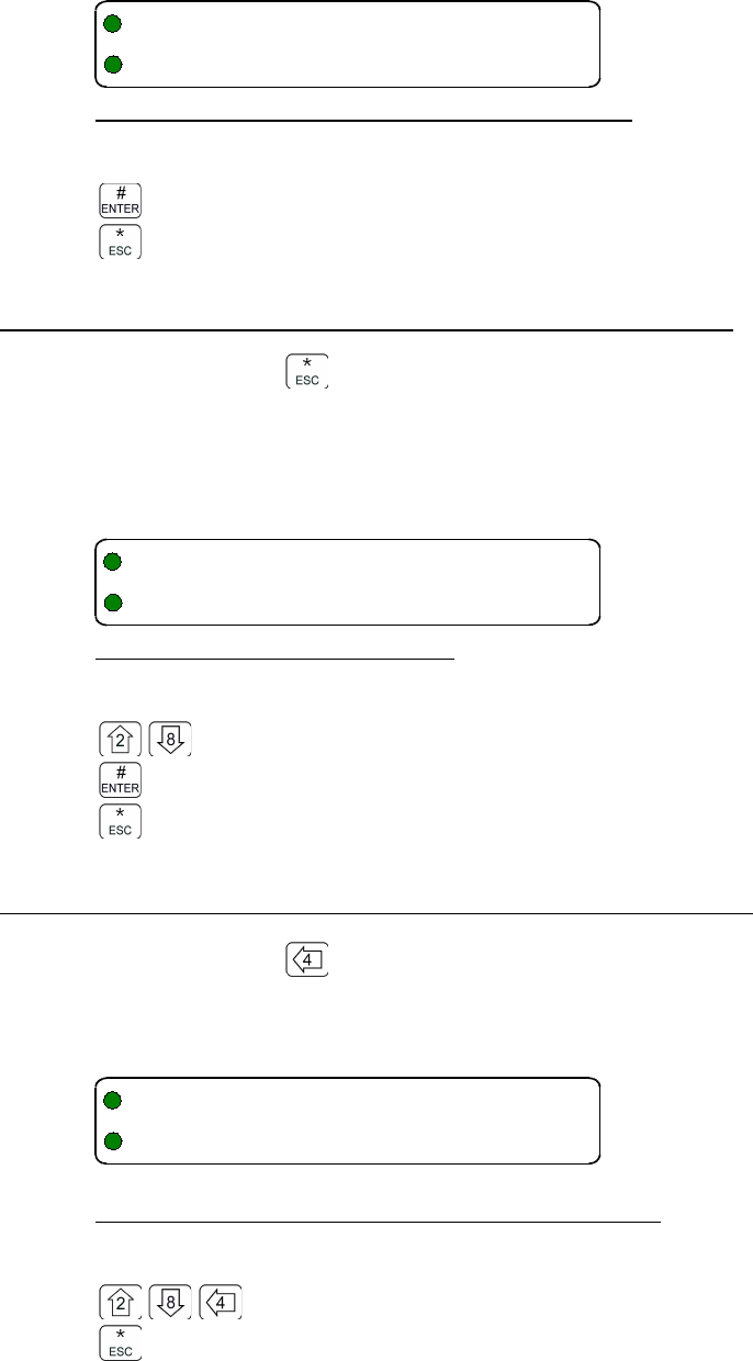
08RE399 TDFM-136B Operating Instructions
Once the above screens have all been passed, then you are given the chance to assign another
key, or to exit.
Figure 3-24. Screen to Assign another key or exit
Edit Keys
assign another
exit
3.3.3 Set Numeric Edit Mode: Decimal or Hexadecimal
Level 3 Key Scope: Main only
Select whether to edit the TalkGroup and the NAC numbers as Hexadecimal (Hex) or as Decimal
numbers. The other parameters are edited in decimal only. Note that 'HEX' is indicated by a
preceding dollar sign (ie $014 is hex '14' or 20 decimal).
Figure 3-25. Selecting Edit mode
Edit Keys
toggle Edit Mode Option: Hex / Decimal Edit.
accept the entry and exit
abandon the entry and exit
3.3.4 Display Firmware Release and Version Information
Level 3 Key Scope: Main only
Display the current firmware release and version information for the various firmware objects in the
transceiver. This information is displayed on the bottom row as follows:
Figure 3-26. Showing the Code Release Information
Edit Keys
Step through firmware information: Main, Bootloader, RF Main, and RF Guard.
exit
42 Technisonic Industries Ltd
"16BFEF(B
6BH%IUF&I
"+2M 3
/2
"4+DV
/M
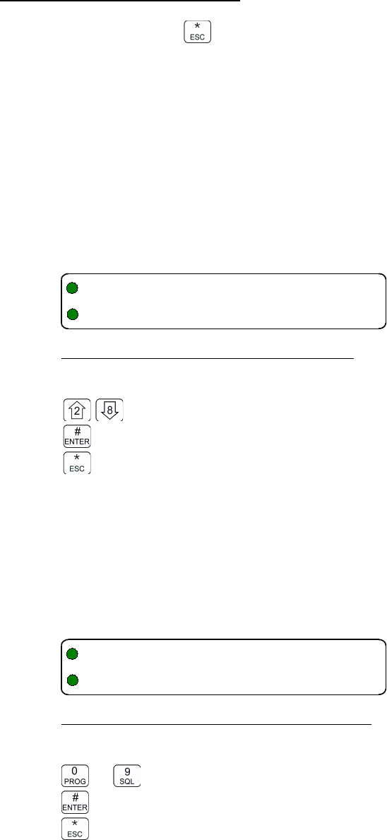
TDFM-136B Operating Instructions 08RE399
3.3.5 Edit Scan Parameters
Level 3 Key Scope: Main only
Edit the parameters that govern the SCAN operation. There are 4 (four) parameters that may be
configured: Revert Mode, Reply Timer, Monitor Timer, and Delay Timer. As with the Create/Edit All
command (L2-1), this command is sequential, allowing the user to move between parameters
using the enter key, at the last parameter, this key accepts all and exits.
L3-5.1. Setting the Revert Mode default: last contacted
The Revert Mode refers to whether the radio will, when keyed, transmit on the selected memory
channel, or on the last contacted memory channel. The radio will only respond on the last
contacted channel for a time determined by the Delay timer setting, once the timer times-out, then
the unit always transmits on the selected channel. The Revert Mode screen is as follows:
Figure 2-27. Select the Scan Revert Mode
Edit Keys
toggle the revert mode
accept the entry and exit
abandon the entry and exit
L3-5.2. Setting the Reply Timer Range: 0-20s, Default: 3 seconds
Set the scan Reply time. This is the time that the radio will monitor a channel on which RF was
received, after all activity on the channel has ended (Rx or Tx). If there is further receive or transmit
activity on the channel, the timer will reset, and start again once the activity has ended. When the
timer times-out the unit will resume scan. If set to zero (0), the unit will resume scan immediately
when channel activity ends.
Figure 2-28. Set the Scan Reply Timer Value
Edit Keys
to decimal mode: enter number, cursor automatically advances
accept the entry and continue
abandon the entry and exit
Technisonic Industries Ltd. 43
"+ 53
./
"+ 53
9(3/
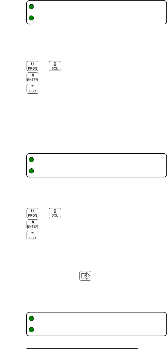
08RE399 TDFM-136B Operating Instructions
L3-5.3. Setting the Monitor Timer Range: 1-90s, Default: 10 seconds
Next, set the scan Monitor time, this is the time that the radio will monitor a channel on which RF
was received, before resuming scanning. Once the timer expires, the unit will break and resume
scan, if the value is set to zero (0) then the unit will monitor the signal as long as it is received.
Figure 3-29. Set the Scan Monitor Timer Value
Edit Keys
to decimal mode: enter number, cursor automatically advances
accept the entry and continue
abandon the entry and exit
L3-5.4. Setting the Delay Timer Range: 0-15s, Default: 5 seconds
The Delay time is the time that the radio will remain monitoring a channel after receiving on that
channel has ended. If the timer is set to zero, (0), then the unit will resume scanning immediately
after receive activity ends. This is the timer that affects the Revert Mode 'Contacted'.
Figure 3-30. Set the Scan Delay Timer Value
Edit Keys
to decimal mode: enter number, cursor automatically advances
accept the entry and continue
abandon the entry and exit
3.3.6 Configure PTT Timer
Level 3 Key Scope: Main only
The PTT timer runs whenever the user holds PTT. The PTT timer duration may be set using this
command: scroll through the available selections: OFF, 30 seconds, 60 seconds and 90 seconds.
Figure 3-31. Set the PTT Timer Value
44 Technisonic Industries Ltd
"+ 53
(3/
"+ 53
(3/
"+5(((3
(3+/#
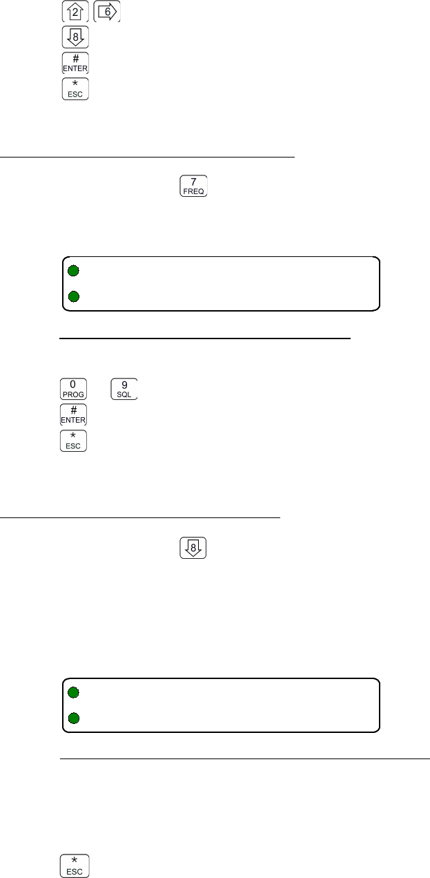
TDFM-136B Operating Instructions 08RE399
Edit Keys
Step up through PTT timer settings
Step down through PTT timer settings
accept the entry and exit
abandon the entry and exit
3.3.7 Side Tone Audio Level Adjust
Level 3 Key Scope: Main only
This command allows the user to adjust the level of side tone, the range of adjustment is 0 to 85,
the default level is 35. The screen shows the currently selected level as shown:
Figure 3-32. Set the Side tone Audio Level
Edit Keys
to decimal mode: enter number, cursor automatically advances
accept the entry and continue
abandon the entry and exit
3.3.8 PC Data Upload/Download
Level 3 Key Scope: Main only
This command allows a user to exchange TDFM-136 channel memory files (records) between a
PC and the transceiver. The unit must be connected to a PC running Windows 95, 98, NT 4.0,
2000, XP, or Win7 and the TiL TDP-136 Radio Communication Software package. When in this
mode, the communication is controlled by the PC software. The transceiver will wait for 25 seconds
to receive a valid record before timing out. The radio will indicate which memory is being
transferred, and when the transfer is complete.
Figure 3-33. Upload/Download Memory Data to/from the PC
If the transceiver has to swap memory space during the download, the activity will be displayed on
the front panel and the download will be completed after a SWAP and ERASE cycle is finished.
There is one user key function:
abandon PC communications mode
Technisonic Industries Ltd. 45
"C33 D5
"0++6
6-./!"C'/11
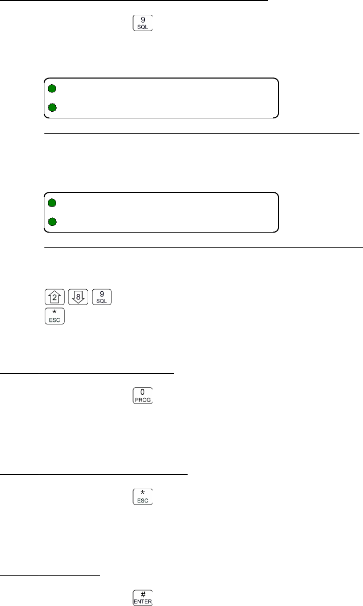
08RE399 TDFM-136B Operating Instructions
3.3.9 Display Channel Squelch Parameters
Level 3 Key Scope: Main and Guard
Display the Squelch parameters for the currently selected channel. The data are displayed as
follows:
Figure 3-34. Display of the Receive Squelch Parameter Values
When displaying the receive parameters, the noise squelch level appears beneath the “Rx” that
starts the line, this space is blank in the transmit parameters display:
Figure 3-35. Display of the Transmit Squelch Parameter Values
Edit Keys
toggle the squelch parameter display between receive (Rx) and transmit (Tx)
exit
3.3.10 Command Level Up
Level 3 Key Scope: Main and Guard
This key selects the next HIGHER Command Level, the Command Level is indicated by a
subscript digit in the 4th character position on the lower row of the display.
3.3.11 Command Level Down
Level 3 Key Scope: Main and Guard
This key selects the next LOWER Command Level, the command Level is indicated by a subscript
digit in the 4th character position on the lower row of the display. See section 2.1 above.
3.3.12 Unused
Level 3 Key Scope:
46 Technisonic Industries Ltd
/((8,6
601771#
(/((8,6
01771#
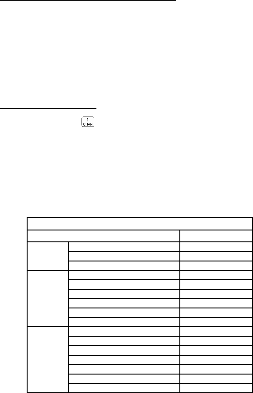
TDFM-136B Operating Instructions 08RE399
3.4 Maintenance Commands (Level 4)
The Maintenance Command Level is a restricted command level; that is, access to these
commands is restricted to authorized personnel. This restriction is enforced by requiring
either a password or requiring that a shunt be placed on a specific set of jumper pins on the
MCU board of the radio.
The Maintenance Commands available allow authorized personnel to set policy for the
radio use, by granting or restricting access to system commands and features.
This command level does not preserve the Normal Operating display characteristics, that
is: the Main and Guard displays are replaced by suitable command prompt information.
3.4.1 Set Default Record
Level 4 Key Scope: Main and Guard
This command allows the user to set up the default record that is used when a user selects Create
New/ Edit All (L2-1). This allows you to determine what parameters you wish to have as system
defaults. Some of the parameters are subject to restrictions set out in L4-9.
NOTE: If these values are set first, and the restrictions are set after, it is possible for the
user to end up using a parameter that you wish to restrict!
The Default Record editor works just like the Create New/ Edit All command (L2-1) except that it
takes you through all the possible squelch combinations so that each selection can be edited.
Table 3-5 shows the parameters that may be edited, and their default values.
Table 3-5. The Channel Template Factory Defaults
Parameter Value
Basic
Scan List 1
Text Description “Desc “
Operating Mode w
Receive
Rx Frequency 141.0000
Rx Squelch Mode x
Rx Squelch TalkGroup Value $0001
Rx Squelch Tone Value 67.0
Rx Squelch Code Value 23
Rx NAC Value $293
Transmit
Tx Frequency 141.0000
Tx Squelch Mode x
Tx Squelch TalkGroup Value $0001
Tx Squelch Tone Value 67.0
Tx Squelch Code Value 23
Tx NAC Value $293
Tx ID Call Value 0000001
Technisonic Industries Ltd. 47
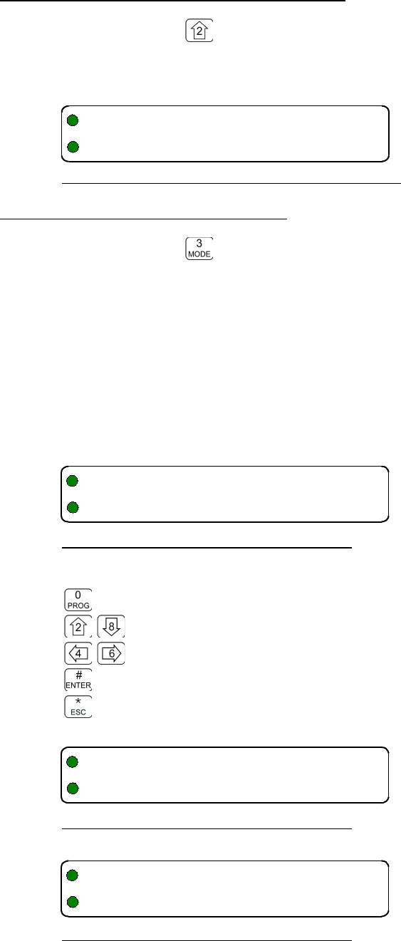
08RE399 TDFM-136B Operating Instructions
3.4.2 Set Restricted Level Access Mode
Level 4 Key Scope: Main and Guard
Select the method to access the restricted command levels. The choices are 'Jumper only' and
'Jumper & Password'.
Figure 3-36. Select the Access Mode from a list.
3.4.3 Set Command Permissions
Level 4 Key Scope: Main and Guard
Select which commands in the command set will be accessible in the Operator Levels (levels 1, 2,
and 3). All the commands in those three levels are affected EXCEPT: ‘PROG’ (0) and ‘ESC’ (*).
The default configuration from the factory has all commands enabled, except L2-2 and L2-8.
The Set Permissions screen shows the level being affected (L1, L2, or L3), followed by the
command number, and an optional 'g' indicating Guard channel operation for that command (if
applicable). The character directly under each number (or associated 'g') indicates whether or not
the command may be accessed. If the command is to be accessible (or enabled), the character is
a is solid round dot; if the command is to be restricted, (or disabled), the character displayed is an
empty dot or donut. The ‘Set Permissions’ for command level 1 screen appears as below:
Figure 3-37. Edit the Level 1 Permissions
Edit Keys
Toggle permission ( @ = enabled, A = disabled
step up/down through Operator Levels
move backward/forward through the available commands
accept the entry and exit
abandon the entry and exit
Figure 2-38. Edit the Level 2 Permissions
Figure 3-39. Edit the Level 3 Permissions
48 Technisonic Industries Ltd
-/1B40BC#B6
@@@@@@@@@@@@@
-1/B14B0C#B6
@@A@@@@@A@@@
-/140C#
@@@@@@@@@
4"1+6
/W39M5
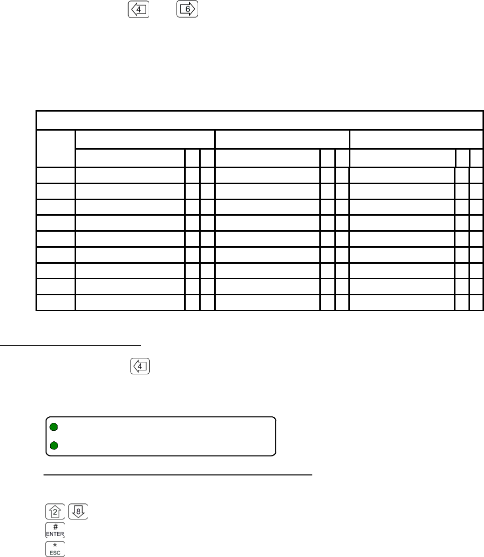
TDFM-136B Operating Instructions 08RE399
Note that the cursor will automatically jump to the next valid column, the cursor will wrap. The ‘g’ indicates a
separate Guard option; for the commands that support this, the Main and Guard can be enabled/disabled
separately. In addition, some of the commands are either channel agnostic, or specific to the Main channel
only and can thus be invoked for Main even when the radio front panel switches are in the Guard position.
For example: with the switches in the Guard position the user can still scroll through the Main
memories using the and keys. These types of commands are available in the Guard
mode, but the permissions are determined by the Main permission. The table below indicates all
the available user commands, and shows the permission mode as follows:
●shows a command that has a distinct permission
●shows a command that is available in Guard, but permission is controlled by Main.
X shows a command that is NOT available for the channel.
Table 3-6. Permission Applicability wrt Command Levels
Cmnd
Num
Level 1 Level 2 Level 3
Command M G Command M G Command M G
1Select MN Memory
●
●
Create/Prog All
●
●
Set Main Boot Memory
●
●
2Brighter
●
●
Copy GD to Main
●
●
Upload to PC
●
●
3Edit Op Mode
●
●
Lock Keypad
●
●
Set Hex/Decimal
●
●
4Scroll MN Memory Down
●
●
Not Used
●
XShow Version
●
●
5Scan
●
XEdit Scan List
●
XEdit Scan Params
●
●
6Scroll MN Memory Up
●
●
Edit Text
●
●
Set PTT Timer
●
●
7Edit Frequency
●
●
Create Shadow
●
XSet Sidetone Level
●
●
8Dimmer
●
●
Copy Main to GD
●
●
Download from PC
●
●
9Edit Squelch
●
●
Edit Unit ID
●
●
Show Squelch
●
●
3.4.4 Set Memory Edit
Level 4 Key Scope: Main and Guard
Individually enable/disable a memory for editing. If disabled then the memory cannot be edited by
any operator level command.
Figure 3-40. Enable/Disable edit of a specific Memory.
Edit Keys
toggle enable/disable of selected memory
accept the entry and exit
abandon the entry and exit
If an attempt is made to edit a disabled memory the error: “Edit Disabled” is displayed on the
prompt line.
Technisonic Industries Ltd. 49
4"4+3
3/11E
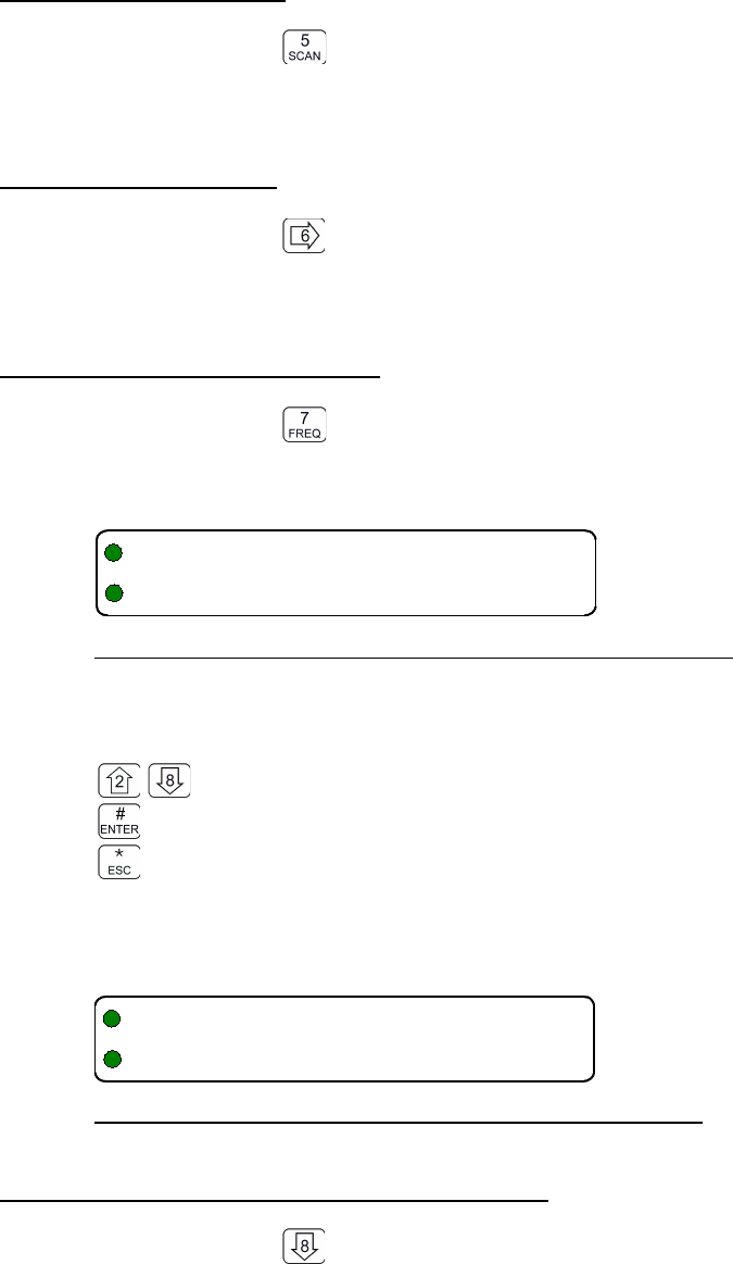
08RE399 TDFM-136B Operating Instructions
3.4.5 L4-5. not used
Level 4 Key Scope: unused
There is no command implemented at this location.
3.4.6 L4-6. not used
Level 4 Key Scope: unused
There is no command implemented at this location.
3.4.7 Set Frequency Display
Level 4 Key Scope:
Individually enable/disable a memories' frequency display. If disabled, the memory position will not
display a frequency. In addition the frequency cannot be edited.
Figure 3-41. The Frequency Display Enable/Disable screen.
The user may change the frequency display for the selected memory as follows:
toggle enable/disable displaying frequency for the selected memory
accept the entry and exit
abandon the entry and exit
Note, once a channel has had it's frequency display disabled, you cannot edit that frequency, an
attempt to do so will cause an error as shown below:
Figure 3-42. A memory with frequency display disabled.
3.4.8 Assign KeyTags to Encryption Keys
Level 4 Key Scope: Main and Guard
Assign a KeyTag to the encryption keys loaded into the radio by following this sequence:
1. Select the key, by SLN, to assign a KeyTag to.
2. Enter the KeyTag
3. Repeat for other keys if desired.
50 Technisonic Industries Ltd
4"0+9
3/119E
11 """"""""3
E
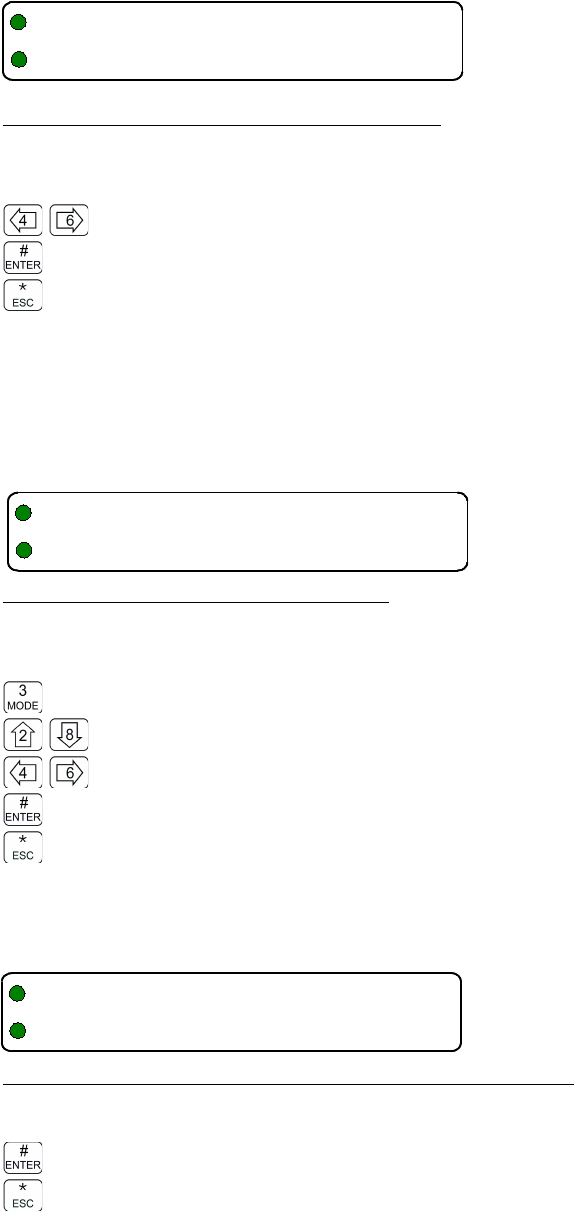
TDFM-136B Operating Instructions 08RE399
L4-8.1 Select Key by SLN. Use this screen to step through the available keys (by SLN).
The encryption algorithm for the key is indicated as well.
Figure 3-43. Step through available keys by SLN.
Edit Keys
move backward/forward through the loaded keys, by SLN
accept the entry and continue
abandon the entry and exit
L4-8.2 Edit the KeyTag for the Selected Key. The system automatically creates
KeyTags named: “Key Tag 01”, through “Key Tag 16”. This screen allows you to change these
names to suit your needs.
The KeyTag is 10 characters and is limited to: Upper & lower case alphabetic, the digits 0-9, a
space, and {! “ # $ % & ' ( ) * + , - . /} not including the brace brackets.
Figure 3-44. The screen to edit the KeyTag.
Edit Keys
Step through the available edit groups (A-Z, a-z, 0-9, + extra characters – see table 3-4)
step up/down through the characters in each edit group
move backward/forward through the available characters
accept the entry and continue
abandon the entry and continue
L4-8.3 Repeat or Exit. When done, you may to loop back and repeat the process for another
key or to exit the editor entirely:
Figure 3-45. The screen to assign another KeyTag or exit.
Edit Keys
accept the entry and continue
abandon the entry and exit
Technisonic Industries Ltd. 51
+ F+-,!>?$%&'
+-,/6-/+
F(B/F(B
+-,/!)*>?$%&'6G
F(B/F(B
6DFH%I8&I
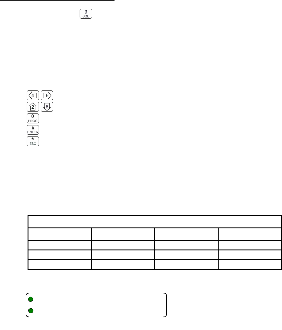
08RE399 TDFM-136B Operating Instructions
3.4.9 Set Squelch Restrictions
Level 4 Key Scope: Main and Guard
You may restrict user access to the Squelch modes. The restricting hierarchy is as follows:
•squelch mode select restrict – limit which squelch modes may be selected.
•squelch mode edit restrict – limit which squelch modes the user may edit the value of
•squelch mode value restrict - limit the range of values for available in a squelch mode
These features are described in the sections below. The editor operates as follows:
Edit Keys
move backward/forward through the restriction screens
step up/down through the parameters for each screen
Toggle the state of the displayed parameter: enabled @ / disabled A
accept the entry and exit
abandon the entry and exit
L4-9.1. Restricting the Squelch Modes Available to Select
You can restrict the Squelch Modes that the user can select for each of Analog Rx, Analog Tx,
Digital Rx, and Digital Tx operation. Note that not all Squelch Modes can be restricted, table 2-8
below shows the available Squelch Mode for each Operating Mode and shows which can be
restricted.
Table 3-7 Squelch Modes that can be Restricted
Analog Rx Analog Tx Digital Rx Digital Tx
Tone
Tone
NAC
IDcall
Code
Code
Talkgroup
Inhibit
Inhibit
The screen shown below is an example of the screens that allow you to restrict which Squelch
Modes appear for the user to select when editing Squelch Modes (L1-9, or in L2-1, or L2-7).
Figure 3-46. The Screen to Set Available Squelch Modes for Analog Receive
Here, the user can restrict the individual Squelch Modes that will appear to the user in the Analog
Squelch mode selector for receive, the same can be done for analog transmit.
L4-9.2. Restrict Editing of a Squelch Mode Value
This screen allows you to restrict which Squelch Modes can have their values edited by the user, a
restriction here will still allow the mode to be selected for use, but the value cannot be changed.
52 Technisonic Industries Ltd
+ D /
V/,@
TDFM-136B Operating Instructions 08RE399
Example: if Noise mode is disabled here, then the user can select Noise (for analog Rx operation),
but cannot change the Noise Squelch level.
Figure 3-47. The Screen to Restrict Editing of the Noise Squelch Value
L4-9.3. Restricting the CTCSS Tone and DCS Code Values
The list of both CTCSS Tones and DCS Codes that are available to the user in the related Squelch
Mode editor can be restricted so that only certain Tones and/or Codes are available to the user
during the edit session.
The CTCSS Tone value restrict screen appears as below, here, you can step through the list of all
the CTCSS Tones, and restrict individual tone values from appearing to the user in the CTCSS
Tone selection list.
Figure 3-48. The Screen to Restrict Available CTCSS Tones
The DCS Code value restrict screen appears as below, here, you can step through the list of all the
DCS Codes, and restrict individual code values from appearing to the user in the DCS Code
selection list.
Figure 3-49. Restrict Available DCS Codes
CTCSS Tone or DCS Code entries restricted here will not appear to the user when they are making
a selection.
3.4.10 Command Level Up
Level 4 Key Scope: Main and Guard
Command level navigation: step up one command level.
3.4.11 Command Level Down
Level 4 Key Scope: Main and Guard
Command level navigation: step down one command level.
3.4.12 L4-# not used
Level 4 Key Scope: Main and Guard
Technisonic Industries Ltd. 53
+ D /
V/,@
+ D /V
(++(/0@
+ D /V
+/1@
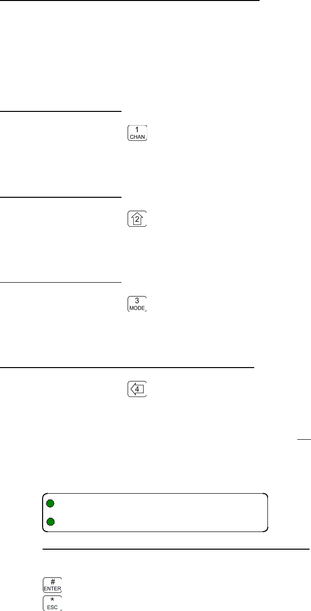
08RE399 TDFM-136B Operating Instructions
3.5 Supervisor Commands (Level 5)
The supervisor Command Level is available to perform a variety of configuration, testing and
tuning functions.
All the functions described in this section are for trained personnel only. If you do not have training
on the use of these commands, leave level 5 by pressing the 'ESC' key.
3.5.1 L5-1 not used
Level 5 Key Scope: -
There is no command implemented at this location.
3.5.2 L5-2 not used
Level 5 Key Scope: -
There is no command implemented at this location.
3.5.3 L5-3 not used
Level 5 Key Scope:
There is no command implemented at this location.
3.5.4 Re-Set Database to Factory Defaults
Level 5 Key Scope: Main and Guard
This command allows you to reset the unit to as shipped from factory.
Note: this will erase all your programmed memories – you will lose all information you have
loaded!
The Re-Set Database screen looks as follows:
Figure 3-50. Erase and Re-Program to Factory Defaults
Edit Keys
accept and erase all data and re-configure the unit
abandon without changing
54 Technisonic Industries Ltd
"4X
QEH%IY$&I,
TDFM-136B Operating Instructions 08RE399
3.5.5 L5-5 not used
Level 5 Key Scope:
There is no command implemented at this location.
3.5.6 Transparent Mode
Level 5 Key Scope: Main and Guard
This command allows you to communicate directly with the RF modules.
Figure 3-51. Transparent Mode
The keys used to operate Transparent Mode are:
step up through available choices (main, guard, off)
step down through available choices
exit mode
exit mode
3.5.7 Edit Passwords
Level 5 Key Scope: Main and Guard
Edit the passwords for access to the restricted command levels. The passwords are edited in
sequence: Maintenance (L4) first followed by Supervisor (L5). Each password is eight characters
long, and may be any of: Upper & lower case alphabetic, the digits 0-9, a space, and {! “ # $ % & ' (
) * + , - . /} not including the brace brackets.
Figure 3-52. Edit Maintenance Password
Edit Keys
Step through the available edit groups (A-Z, a-z, 0-9, + extra characters – see table 3-?)
step up/down through the characters in each edit group
move backward/forward through the available characters
accept the entry and continue
abandon the entry and continue
Technisonic Industries Ltd. 55
"(9/
U
5/
(!)*>?$%&'#
08RE399 TDFM-136B Operating Instructions
Once the Maintenance password has been entered you will automatically advance to the screen to
edit the Supervisor password.
Figure 3-53. Edit Supervisor Password
The editing keys are the same as for the Maintenance password.
3.5.8 Run Bootloader
Level 5 Key Scope: Main and Guard
This command allows you to run the Bootloader in order to load new operating code. Note that the
Bootloader is a separate piece of code and does not run under the radio code, so once started, the
control is handed to the Bootloader. See Bootloader operating instructions.
Bootloader operation is for trained personnel only.
To use the bootloader you must have the unit attached to a correctly configured PC.
You can erase all information in the radio using the bootloader.
The Bootloader screen will look similar to this:
Figure 3-54. The Bootloader Screen
3.5.9 Set Unit ID (UID)
Level 5 Key Scope: Main and Guard
This command allows you to change the Unit ID number for both the Main and the Guard RF
modules depending on the front panel switch position. The UID is a seven digit decimal number in
the range 0000001 to 9,999,999. Note that leading zeros must be entered. The edit screen
appears as follows:
Figure 3-55. Set Unit ID Number (screen for Main shown)
The keys used to edit the UID parameter are:
Edit Keys
to decimal mode: enter number, cursor automatically advances
accept the entry and continue
abandon the entry and exit
56 Technisonic Industries Ltd
"#+:;
:;%/
+95/
(!)*>?$%&'#
("T
V/1
TDFM-136B Operating Instructions 08RE399
3.5.10 L5-0 not used
Level 5 Key Scope:
There is no command implemented at this location.
3.5.11 Command Level Down
Level 5 Key Scope: Main and Guard
Command level navigation: step down one command level.
3.5.12 L5-# not used
Level 5 Key Scope:
There is no command implemented at this location.
Technisonic Industries Ltd. 57
08RE399 TDFM-136B Operating Instructions
58 Technisonic Industries Ltd
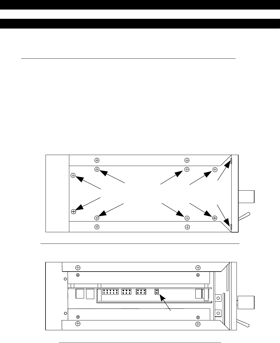
TDFM-136B Operating Instructions 08RE399
SECT ION 4
APPEND ICI ES
The appendicies contain information referred to from the main document.
4.1 Appendix A. Installing the Jumper for Restricted Level Access.
To do so refer to figures 4-1 and 4-2, and follow these steps:
1. Ensure that the power to the unit is off.
2. Remove the left hand side cover (10 philips screws)
3. Locate the 6 pin jumper field (approximately half way between the front and rear of the
radio).
4. Place a 0.1” shunt on the set of jumper pins closest to the front of the radio.
The user can now select level 4 (maintenance mode).
Figure 4-1. The Screw positions to Remove the Left Hand Side Panel
Figure 4-2. The Shunt Position to Enable Level 4 Access
NOTE: Jumper access to this command level MUST BE DISABLED when the radio is used in flight.
Restricted commands are NOT required for flight operation.
Use of restricted commands in flight may cause data loss or lock the transceiver.
Technisonic Industries Ltd. 59
Place shunt on Jumper closest to front

08RE399 TDFM-136B Operating Instructions
4.2 Appendix B. CTCSS Tone and DCS Code Tables
Table 4-1 Table 4-2
CTCSS Tones (Hz.) DCS Codes
67.0
23 315
69.3
25 331
71.9
26 343
74.4
31 346
77.0
32 351
79.7
43
364
82.5
47
365
85.4 51 371
88.5 54
411
91.5 65
412
94.8
71
413
97.4 72
423
100.0
73
431
103.5
74 432
107.2
114 445
110.9 115 464
114.8 116 465
118.8 125 466
123.0 131 503
127.3 132 506
131.8 134 516
136.5 143 532
141.3 152 546
146.2 155 565
151.4 156 606
156.7 162 612
162.2 165 624
167.9 172 627
173.8
174 631
179.9 205 632
186.2 223 654
192.8 226 662
203.5
243
664
206.5 244 703
210.7 245
712
218.1 251 723
225.7 261 731
229.1 263 732
233.6 265 734
241.8 271 743
250.3 306 754
254.8 311
60 Technisonic Industries Ltd

TDFM-136B Operating Instructions 08RE399
4.3 Appendix C. Programming Channel data using TDP and a PC.
Technisonic Industries Ltd. 61
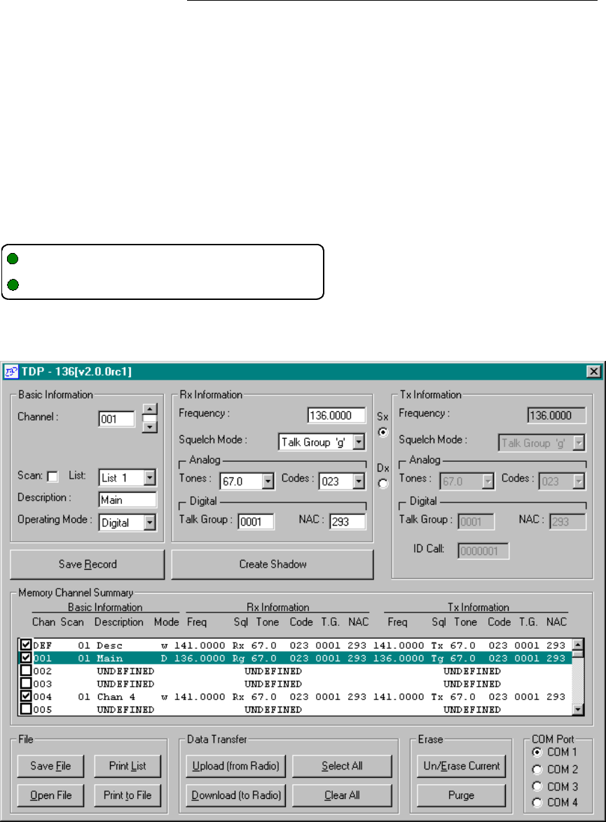
08RE399 TDFM-136B Operating Instructions
The TDFM-136B supports loading memory data from a PC using TDP-136 software. Be
sure not to use 'MultiTDP' it does not work with this radio.
For full information see the “TDP-136 PC Software Installation & Operating Instructions”,
TiL #00RE277.
In brief, you will need:
A PC running Microsoft Windows (2000, NT, XP, Vista, or Win7), with the correct TDP
installed.
A suitable connecting cable (TiL #003469-1) or a TiL Radio Test Jig (04T139) and serial
cable (9 pin).
24-30Volt power supply @ 3A.
With the unit powered up and correctly connected to a PC, put the radio into PC
Communications Mode (use command L3-8). Once done you will see:
Start the TDP, you will see something like:
62 Technisonic Industries Ltd
"C33 D5
TDFM-136B Operating Instructions 08RE399
Once the transceiver is in PC communications mode, and is correctly attached to a PC
running the TDP software, then the control of all functions is via the software running on the
PC.
You can get the contents of the transceiver using the “Upload (from Radio)” button.
You can edit a record by clicking on the appropriate line in the memory summary box and
then changing the values in the “Basic Information”, “Rx Information”, and “Tx Information”
blocks at the top of the screen. Note that the “Tx” function is un-editable unless you have
the duplex “Dx” button selected. Press 'Save Record” when done.
Create a new record by selecting a Memory number using the “Channel” scroll widget, then
fill out the appropriate information for Basic, Rx and Tx. Again, press “Save Record” when
done.
Once you have modified a file, or created a new one, press “Download (to Radio)”, and the
records will be transferred to the transceiver.
Technisonic Industries Ltd. 63

08RE399 TDFM-136B Operating Instructions
4.4 Appendix C. 2.5 kHz & 6.25 kHz Valid Frequencies
Table 4-3 shows the frequencies that the transceiver may be tuned to, both 2.5
kHz. steps and 6.25 kHz. steps are supported. Frequencies from 136.0000 to
136.0975 Hz. are shown, the pattern repeats every 100kHz. through the band.
Table 4-3
2.5 kHz 2.5 and 6.25 kHz 6.25 kHz
136.00000 136.00000 136.00000
136.00250 136.00250
136.00500 136.00500
136.00625 136.00625
136.00750 136.00750
136.01000 136.01000
136.01250 136.01250 136.01250
136.01500 136.01500
136.01750 136.01750
136.01875 136.01875
136.02000 136.02000
136.02250 136.02250
136.02500 136.02500 136.02500
136.02750 136.02750
136.03000 136.03000
136.03125 136.03125
136.03250 136.03250
136.03500 136.03500
136.03750 136.03750 136.03750
136.04000 136.04000
136.04250 136.04250
136.04375 136.04375
136.04500 136.04500
136.04750 136.04750
136.05000 136.05000 136.05000
136.05250 136.05250
136.05500 136.05500
136.05625 136.05625
136.05750 136.05750
136.06000 136.06000
136.06250 136.06250 136.06250
136.06500 136.06500
136.06750 136.06750
136.06875 136.06875
136.07000 136.07000
136.07250 136.07250
136.07500 136.07500 136.07500
136.07750 136.07750
136.08000 136.08000
136.08125 136.08125
136.08250 136.08250
136.08500 136.08500
136.08750 136.08750 136.08750
136.09000 136.09000
136.09250 136.09250
136.09375 136.09375
136.09500 136.09500
136.09750 136.0975
64 Technisonic Industries Ltd

TDFM-136B Operating Instructions 08RE399
4.5 Appendix D. Default Tables
This Appendix shows various system default parameters.
Table 4-4. The Memory Template Factory Defaults
Parameter Value
Basic
Scan List 1
Text Description “Desc “
Operating Mode w
Receive
Rx Frequency 141.0000
Rx Squelch Mode x
Rx Squelch TalkGroup Value $0001
Rx Squelch Tone Value 67.0
Rx Squelch Code Value 23
Rx NAC Value $293
Transmit
Tx Frequency 141.0000
Tx Squelch Mode x
Tx Squelch TalkGroup Value $0001
Tx Squelch Tone Value 67.0
Tx Squelch Code Value 23
Tx NAC Value $293
Tx ID Call Value 0000001
Table 4-5. Configuration Parameters
Parameter
Value
TalkGroup & NAC Edit Mode
Hexadecimal
PTT Timer
90 seconds
Sidetone Volume
63
Noise Squelch Level
10
Home Memory
001
Main Channel Boot Memory
Last Used
Table 4-6. Scan Parameters
Parameter
Value
Revert Mode
last contacted
Reply Timer
3 seconds
Monitor Timer
10 seconds
Delay Timer
5 seconds
Table 4-7. Unit Identification (UID)
Main 0000001
Guard 0000002
Table 4-8. Restricted Level Passwords
Maintenance
00000000
Supervisor
10000000
Technisonic Industries Ltd. 65