Technisonic TDFM-7300-3 Multiband FM Airborne Transceiver User Manual 11re436
Technisonic Industries Limited Multiband FM Airborne Transceiver 11re436
UserManual.wiki
>
Technisonic
>
TDFM 7300 3 User Manual
User Manual
Navigation menu
Upload a User Manual
Namespaces
Wiki Guide
HTML
PDF
Info
Views
User Manual
Discussion / Help
Navigation
![TDFM-7300-3 Installation & Operating Instructions TiL 11RE436 iii REVISION HISTORY [ 11RE436 ] REV SECTION - PAGE - DESCRIPTION DATE Edited by NOTES](https://usermanual.wiki/Technisonic/TDFM-7300-3/User-Guide-1544275-Page-3.png)
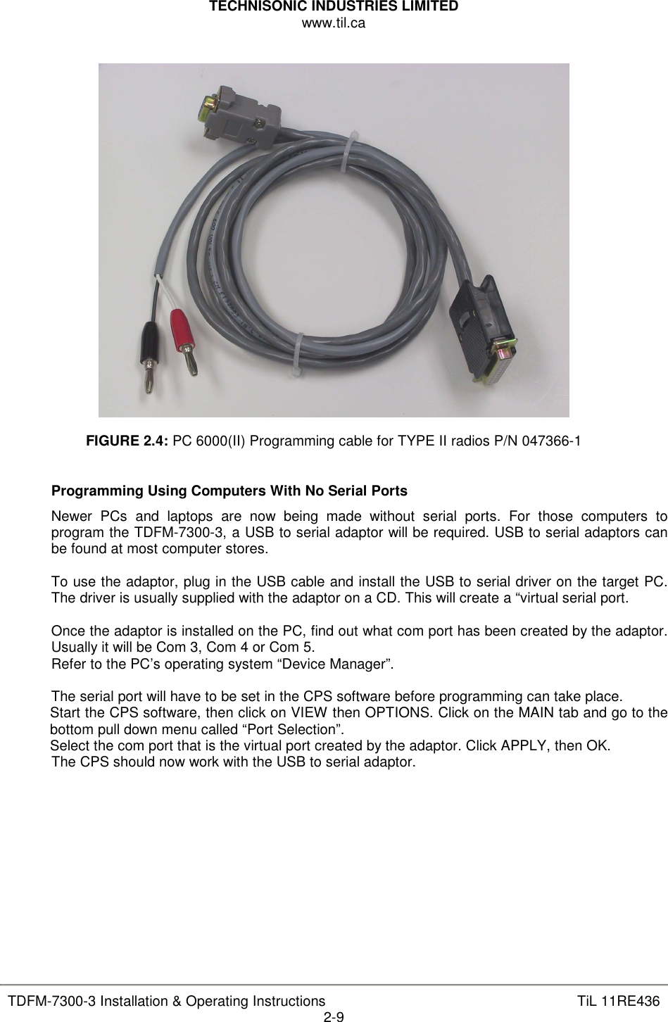
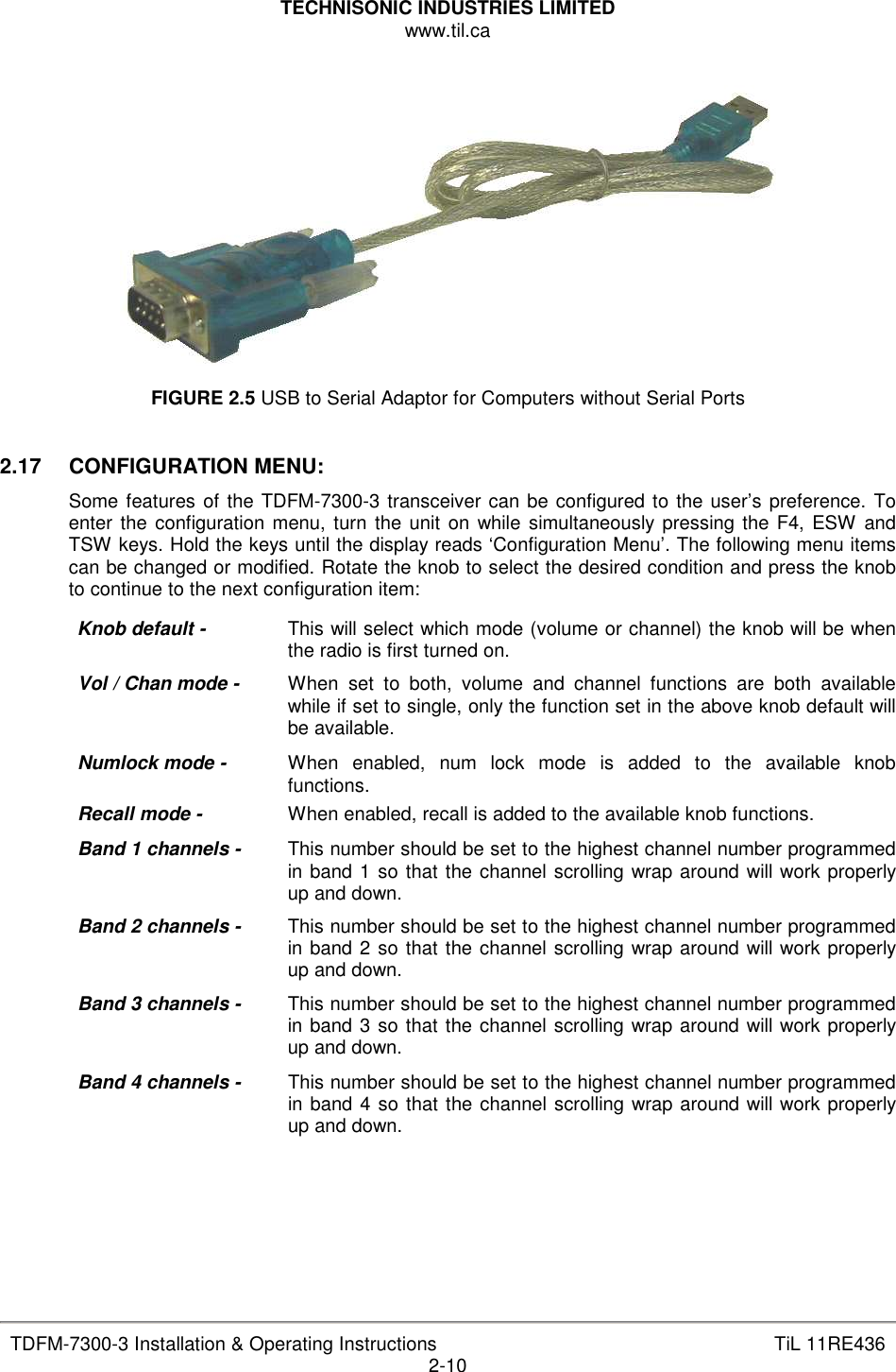
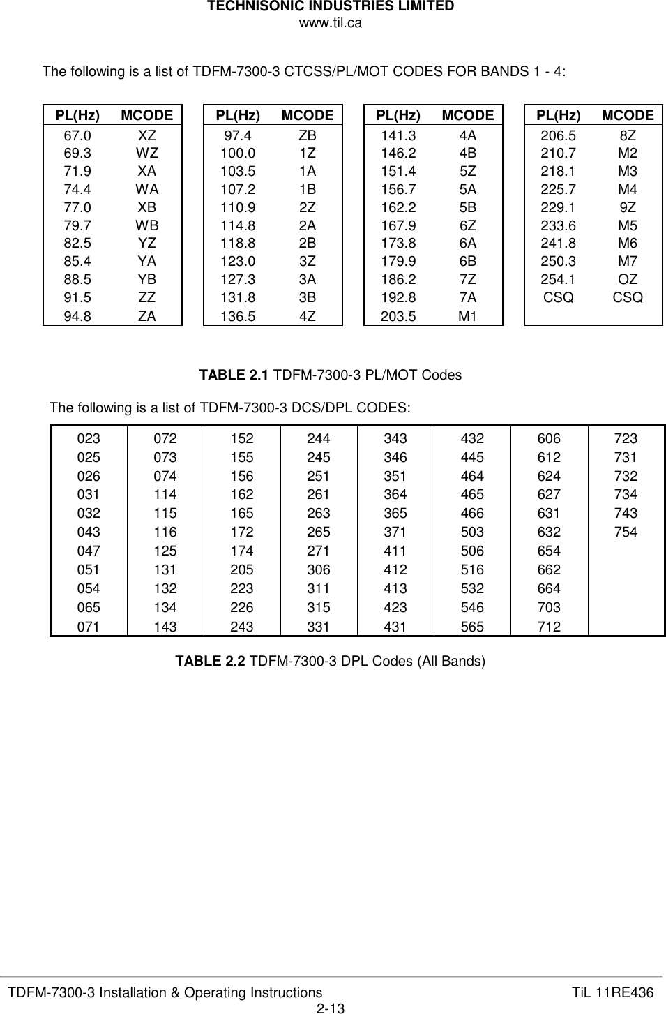
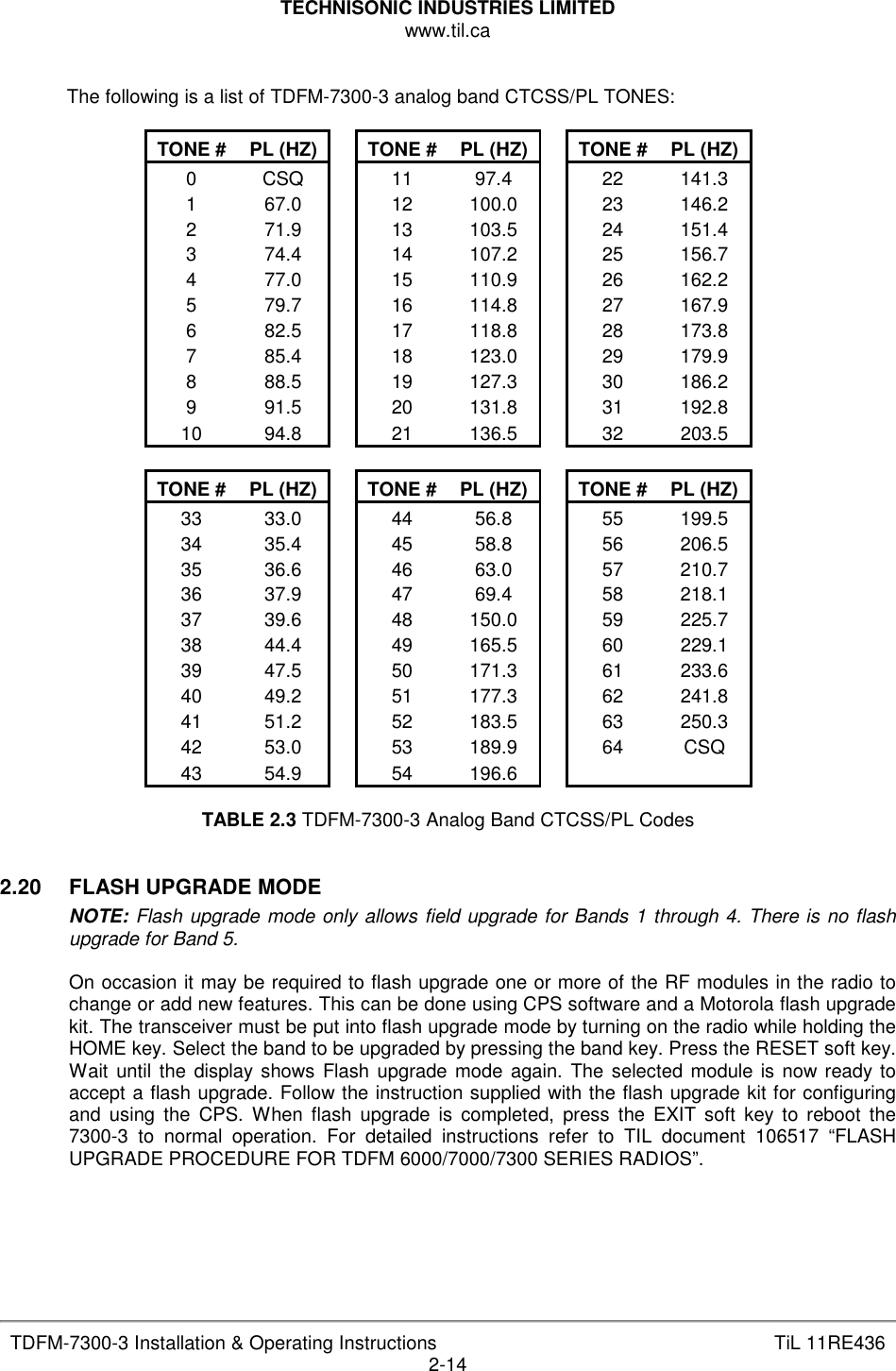
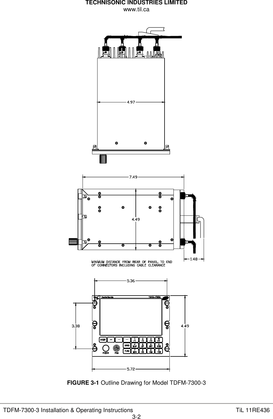
![TECHNISONIC INDUSTRIES LIMITED www.til.ca TDFM-7300-3 Installation & Operating Instructions TiL 11RE436 vi LIST OF FIGURES FIGURE TITLE PAGE 2.1 Front Panel Controls – TDFM-7300-3 Series Transceivers .................................................. 2-1 2.2 PC 7000(II) Programming cable for TYPE II radios P/N 047365-1 ........................................ 2-8 2.3 Encryption Keyload cable for TYPE II radios P/N 037348-1 .................................................. 2-8 2.4 PC 6000(II) Programming cable for TYPE II radios P/N 047366-1 ........................................ 2-9 2.5 USB to Serial Adaptor for Computers without Serial Ports .................................................... 2-10 3.1 Outline Drawing ................................................................................................................... 3-2 3.2a Wiring Connections ............................................................................................................. 3-6 3.2b Wiring Connections Notes ................................................................................................... 3-7 LIST OF TABLES TABLE TITLE PAGE 2.1 TDFM 7300-3 Series PL/MOT Codes .................................................................................. 2-13 2.2 TDFM 7300-3 Series DPL Codes (All Bands) ....................................................................... 2-13 2.3 TDFM 7300-3 Analog Band CTCSS/PL Codes .................................................................... 2-14 3.1 Wire connections on a 25-Pin FEMALE D-Connector .......................................................... 3-3 3.2 Wire connections on a 9-Pin FEMALE D-Connector ............................................................ 3-3 3.3 Wire connections on a 15-Pin [high-density] FEMALE D-Connector ..................................... 3-4](https://usermanual.wiki/Technisonic/TDFM-7300-3/User-Guide-1544275-Page-7.png)
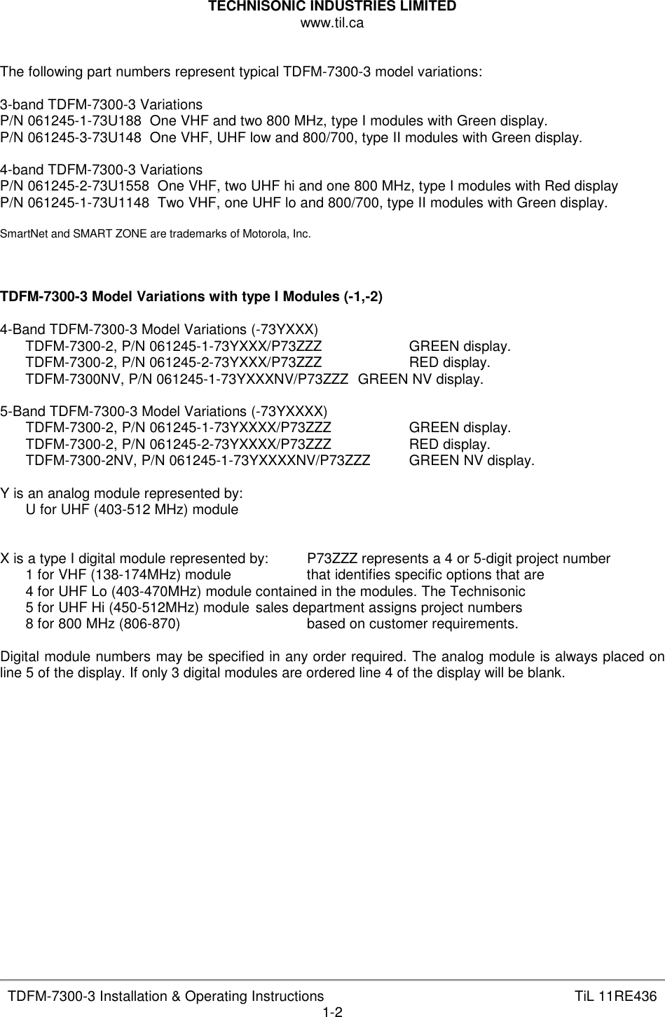


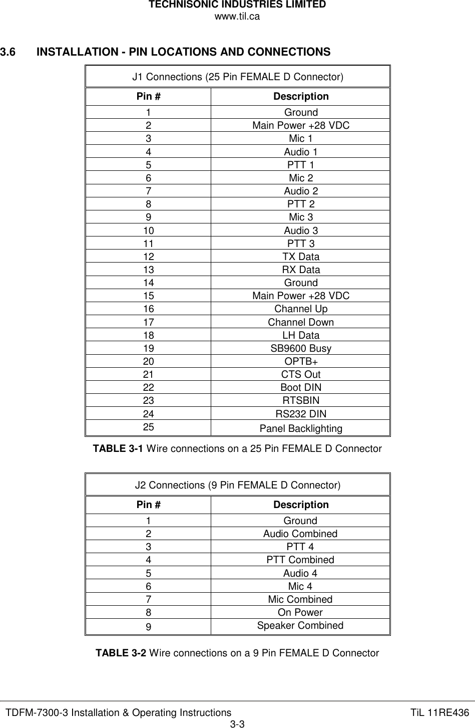
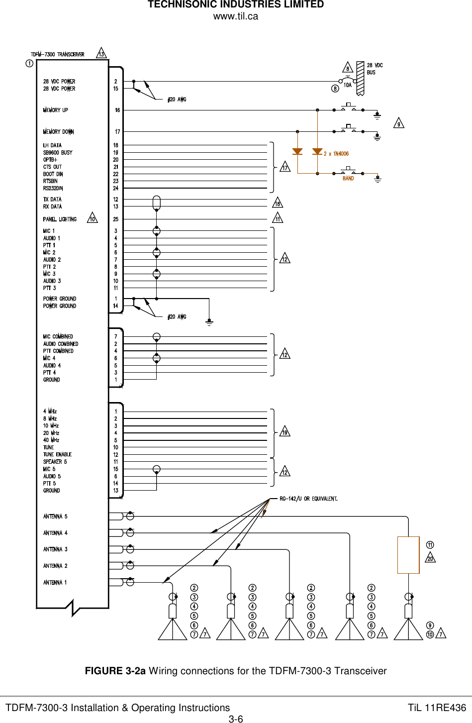
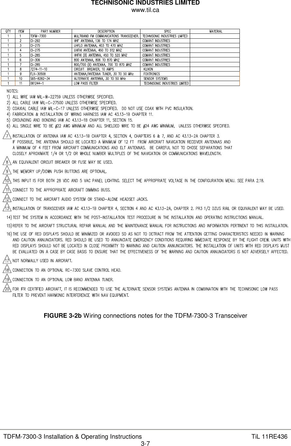
![TECHNISONIC INDUSTRIES LIMITED www.til.ca TDFM-7300-3 Installation & Operating Instructions TiL 11RE436 3-4 P1 Connections (15 Pin [high density] FEMALE D Connector) Pin # Description 1 4 MHz 2 8 MHz 3 10 MHz 4 20 MHz 5 40 MHz 6 Audio 5 7 No connection 8 No connection 9 No connection 10 Tune Indicator 11 Speaker 5 12 Tune Enable 13 Ground 14 PTT5 15 Mic 5 TABLE 3-3 Wire connections on a 15 Pin [high-density] FEMALE D Connector 3.7 INSTALLATION (WIRING INSTRUCTIONS) Figure 3-2 shows all required connections and recommended wire sizes for the TDFM-7300-3 transceiver. 3.8 MAIN GROUND: J1 (PINS 1 AND 14) Both pins should be connected to ground. The main ground is internally connected to the chassis. 3.9 MAIN POWER: + 28VDC – J1 (PINS 2 AND 15) Both pins should be connected to +28 volts DC +/- 15%. 3.10 MIC 1, 2, 3, 4 AND 5: J1 (PINS 3, 6, 9), J2 (PIN 6) AND P1 (PIN 15) The microphone input signals shall be connected using shielded wire with the shield connected to ground (pin 1 or 14). It is recommended for best results to leave the other end of the shield floating to prevent ground currents unless you are connecting to an audio panel with floating hi and lo inputs (like the Technisonic A710 or A711 series) in which case the shield must be connected to the lo input. 3.11 AUDIO 1, 2, 3, 4, 5 AND COMBINED: J1(PINS 4, 7, 10) J2 (PINS 5, 2) AND P1 (PIN 6) Audio outputs are 600 ohms impedance against ground. The output power is 600 mW maximum. Unused outputs do not have to be terminated and should be left unconnected.](https://usermanual.wiki/Technisonic/TDFM-7300-3/User-Guide-1544275-Page-35.png)