Technisonic TFM-138 VHF/FM TRANSCEIVER User Manual D PDF 98re243 7
Technisonic Industries Limited VHF/FM TRANSCEIVER D PDF 98re243 7
Contents
- 1. USER MANUA 1 OF 4
- 2. USER MANUAL 2 OF 4
- 3. USER MANUAL 3 OF 4
- 4. USER MANUAL 4 OF 5
- 5. USER MANUAL 5 OF 5
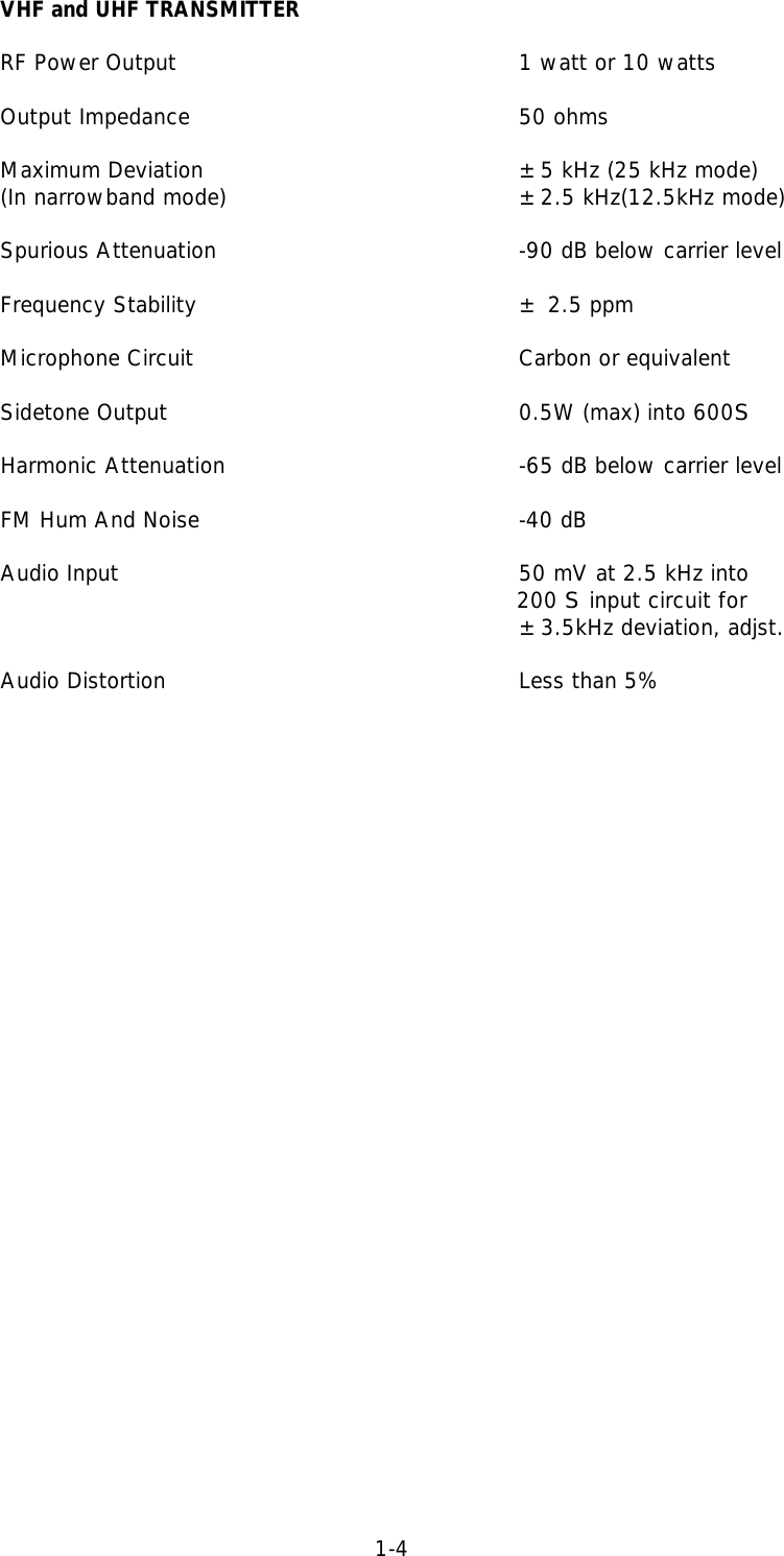
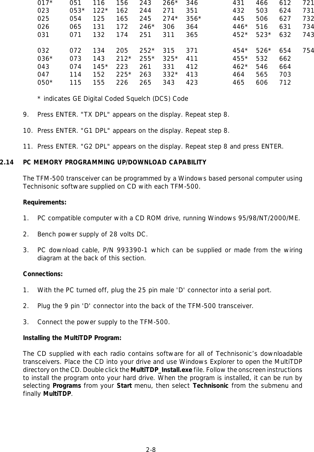
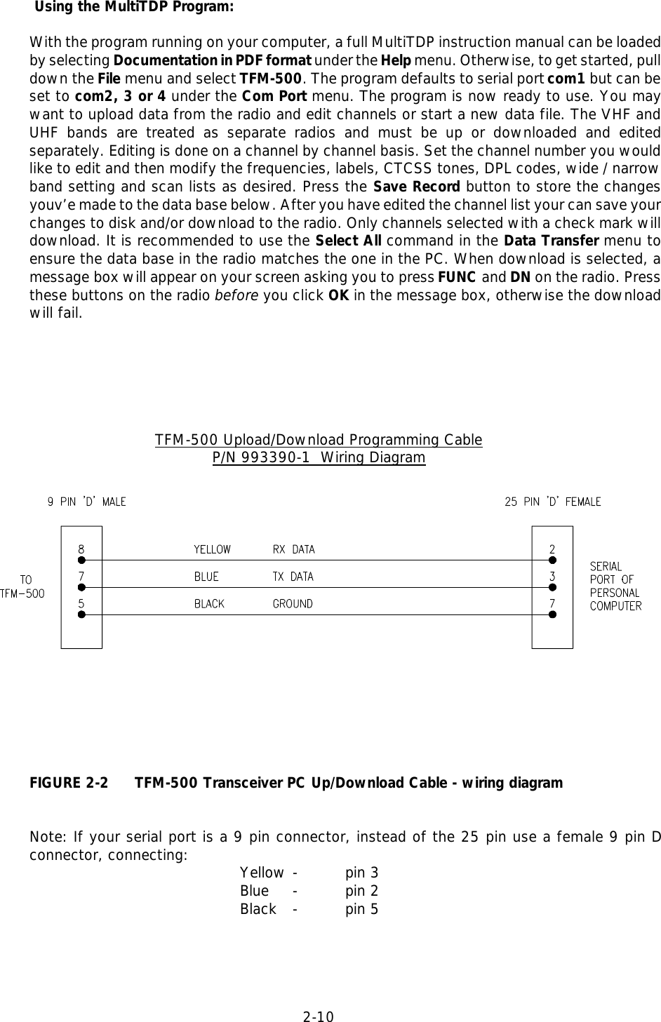
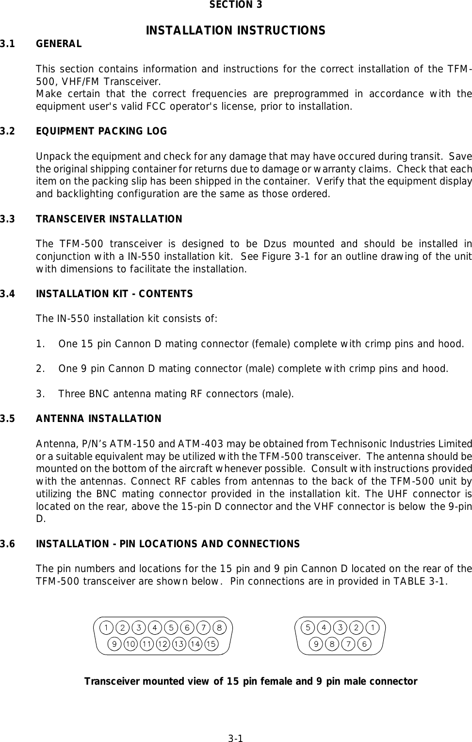
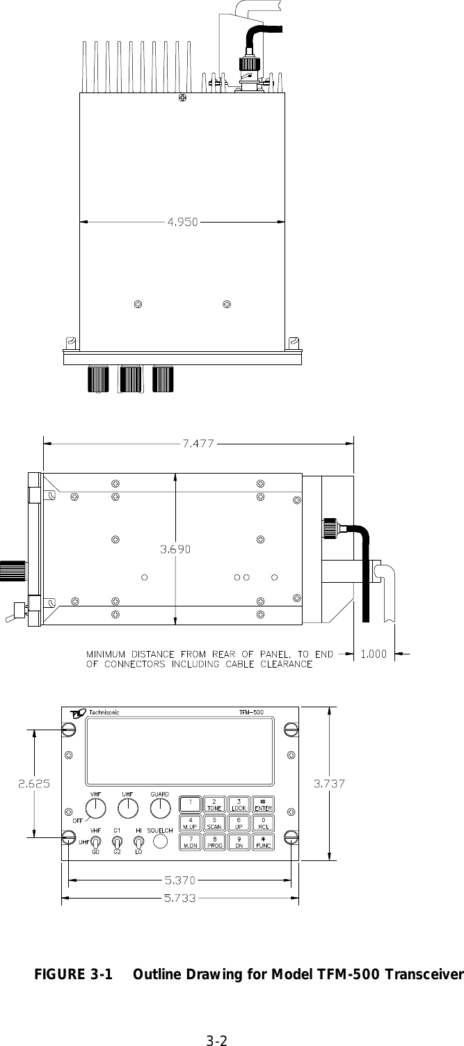
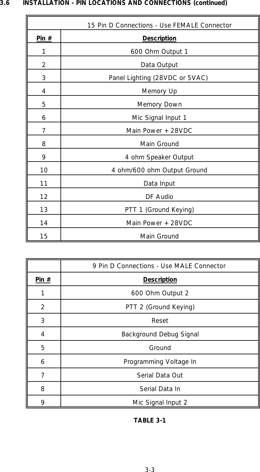
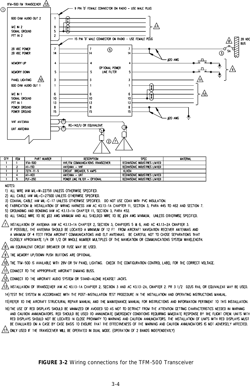
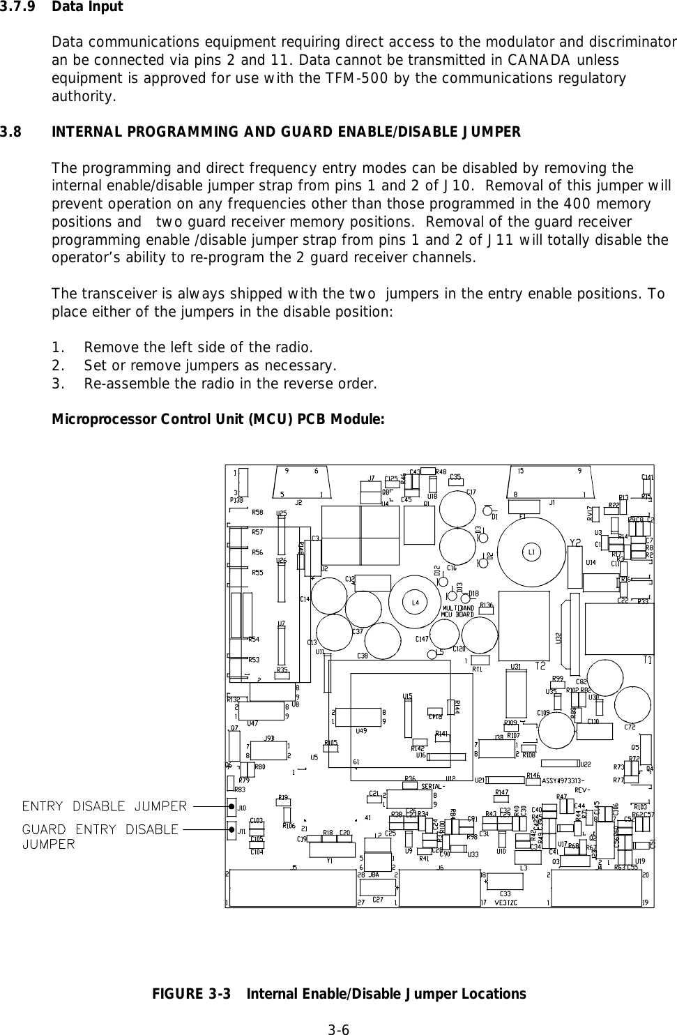
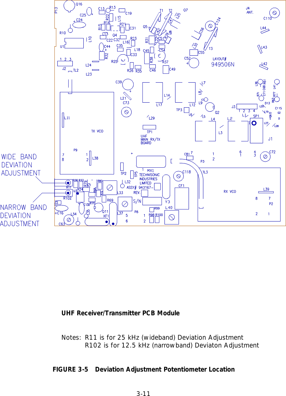
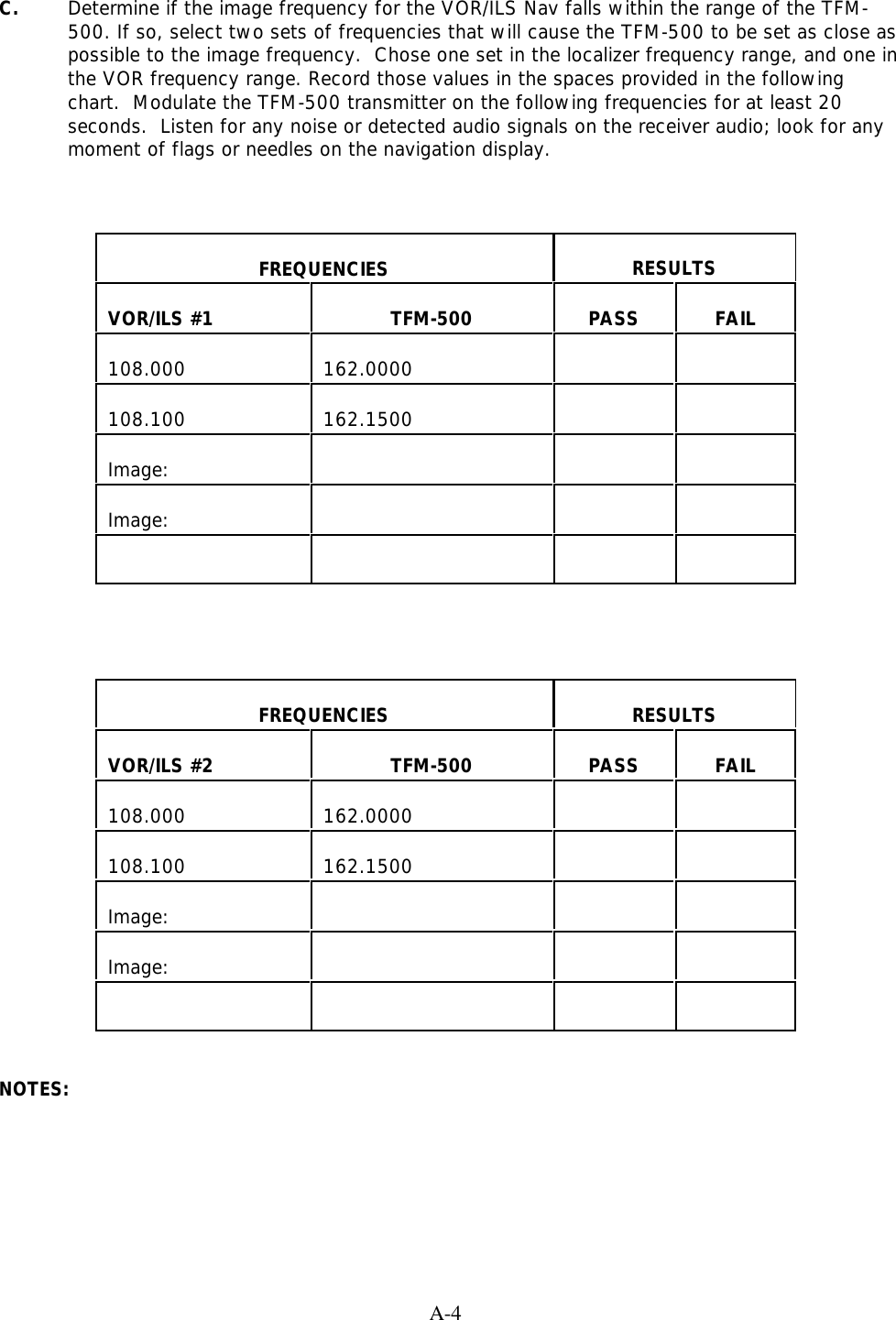
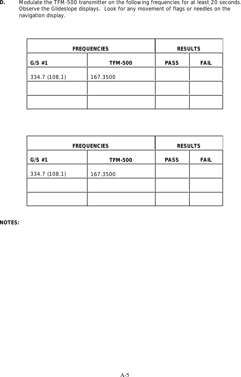
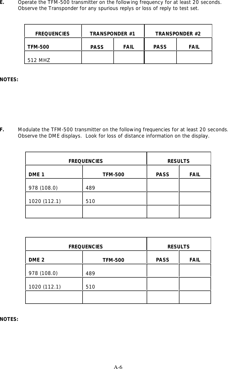
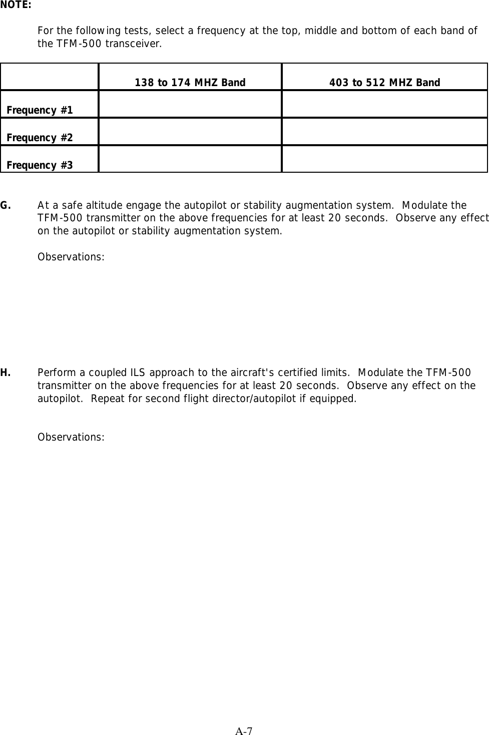
USER MANUAL 3 OF 4