Techsan I and C LM15 LCD Monitor User Manual 1
Techsan I & C Co., Ltd. LCD Monitor 1
User Manual

FCC ID : RJ5LM15
REPORT NO. : HCT-F04-0502 HYUNDAI C–TECH
ATTACHMENT E.
- USER’S MANUAL
CAUTION : TO REDUCE THE RISK OF
ELECTRIC SHOCK, DO NOT
REMOVE COVER (OR BACK).
NO USER-SERVICEABLE PARTS
INSIDE. REFER SERVICING TO
QUALIFIED SERVICE PERSONNEL.
This symbol is intended to alert the user to the
presence of uninsulated “dangerous voltage”within
the product’s enclosure that may be of sufficient
magnitude to constitute a risk of electric shock to
persons.
This symbol is intended to alert the user to the
presence of important operating and maintenance
(servicing) instructions in the literature
accompanying the appliance.
“W A R N I N G - To Reduce The Risk Of Fire Or Electric Shock, Do Not
Expose This Apparatus To Rain Or Moisture.”
“Apparatus shall not be exposed to dripping or splashing and no objects filled
with liquids, such as vases, shall be placed on the apparatus.”
“C A U T I O N - These servicing instructions are for use by qualified service
personnel only. To reduce the risk of electric shock, do not perform any
servicing other than that contained in the operating instructions unless you are
qualified to do so.”
RISK OF ELECTRIC SHOCK
DO NOT OPEN
CAUTION
WARNING & CAUTION

Important Safety Instructions
1) Read these instructions.
2) Keep these instructions.
3) Heed all warnings.
4) Follow all instructions.
5) Do not use this apparatus near water.
6) Clean only with a dry cloth.
7) Do not block any of the ventilation openings. Install in accordance with the
manufacturer's instructions.
8) Do not install near any heat sources such as radiators, heat registers, stoves, or
other apparatus (including amplifiers) that produce heat.
9) Do not defeat the safety purpose of the polarized or grounding type plug. A
polarized plug has two blades with one wider than the other. A grounding type
plug has two blades and a third grounding prong. The wide blade or the third
prong is provided for your safety. When the provided plug does not fit into
your outlet, consult an electrician for replacement of the obsolete outlet.
10) Protect the power cord from being walked on or pinched particularly at plugs,
convenience receptacles, and the point where they exit from the apparatus.
11) Only use the attachments/accessories specified by the manufacturer.
12) Use only with a cart, stand, tripod, bracket, or table specified by the
manufacturer, or sold with the apparatus. When a cart is used, use caution
when moving the cart/apparatus combination to avoid injury from tip-over.
13) Unplug this apparatus during lightning storms or when unused for long periods
of time.
14) Refer all servicing to qualified service personnel. Servicing is required when
the apparatus has been damaged in any way, such as power supply cord or plug
is damaged, liquid has been spilled or objects have fallen into the apparatus, the
apparatus has been exposed to rain or moisture, does not operate normally, or
has been dropped.

FCC (Federal communication commission) Information
T
his product has been tested and found to comply with the limits for a TV
Broadcast Receiver, pursuant to Part 15 of the FCC Rules. These limits are
designed to provide reasonable protection against harmful interference in a
residential installation. This product generates, uses and can radiate radio
frequency energy and, if not installed and used in accordance with the instructions,
may cause harmful interference to radio communications. If this product does
cause or receive interference, which can be determined by turning product off and
on, the user is encouraged to try to correct the interference by one of the following
measures:
Reorient or relocate the TV antenna.
Increase the separation between TV and other product.
Connect TV into separate outlet from other product.
Consult the dealer or an experienced radio/TV technician for help.
FCC Caution: Any changes or modifications not expressly approved by the party
responsible for compliance could void the user's authority to operate this product.
U.S.A.
U.S.FEDERAL COMMUNICATIONS COMMISSION
RADIO FREQUENCY INTERFERENCE STATEMENT
INFORMATION TO THE USER
NOTE : This equipment has been tested and found to comply with the limits for a
Class B digital device pursuant to Part 15 of the FCC Rules.
These limits are designed to provide reasonable protection against harmful
Interference in a residential installation.
This equipment generates, uses, and can radiate radio frequency energy and, if
Not installed and used in accordance with the instructions, may cause harmful
Interference to radio communications.
However, there is no guarantee that interference will not occur in a particular
Installation.
If this equipment does cause harmful interference to radio or television reception,
Which can be determined by turning the equipment off and on, the user is
encouraged to try to correct the interference by one or more of the following
measures:
Reorient or relocate the receiving antenna.
Increase the separation between the equipment and receiver.
Connect the equipment into an outlet of a circuit different from that
to which the receiver is connected.
Consult the dealer or an experienced radio/TV technician for assistance.
Changes or modification not expressly approved by the party responsible for
Compliance could void the user’s authority to operate the equipment.
Connecting of peripherals requires the use of grounded shielded signal cables.

1. Packing List
2. Safety Instructions
3. Features
4. Installation
4-1 Monitor Description
4-2 Connecting To The Computer
5. Monitor Adjustment
5-1 OSD Menu Description
5-2 Accessing the OSD Menu
5-3 OSD Menu Descripyion
6. Specifications
6-1 Monitor Specification
6-2 Video Input Connector
6-3 Resolutions Supported
7. Troubleshooting
8. Descriptions of Technical Terms
1
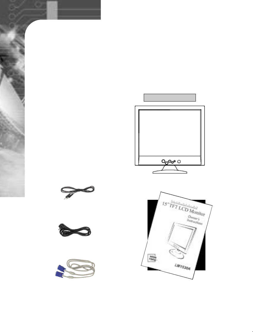
Your new ‘LCD Monitor’should contain the following items:
- LCD Monitor
- AUDIO CABLE
- 15pin D-SUB Signal Cable
- Owner’s Instructions
- Power Cord
2
※The power cord may be changed to accommodate electrical outlets worldwide.
1
Packing List
LM1530A
15pin D-SUB Signal Cable
AUDIO CABLE
Power Cord
Owner’s Instructions

3
Do not place heavy objects on the power cord.
Do not use your monitor near water.
Turn off the monitor if there is thundering and lightening.
Do not open your monitor. There are no user serviceable parts inside.
Opening the case might expose you a hazardous shock.
Do not place the monitor on an unstable table or stand.
Do not insert small conductive objects into the monitor. They might cause
a short or a hazardous shock.
Adjust the height of monitor so that the top of the screen is below
approximately 10 degrees.
If reflected light makes it hard to see the screen, use a glare filter.
Clean the LCD screen of the monitor surface with a lint-free, non-abrasive
cloth. Avoid using any cleaner or solvent, such as benzene.
Do not operate the monitor in a place that is extremly hot, humid or dusty.
- Proper temperature: 5 ~ 35 ℃
- Humidity: 20 ~ 80 RH
Safety Instructions
2

4
Screen: 15.0”viewable XGA (1024*768) resolution LCD module and
space-saving slim design.
Plug and Play Function: Implementation of DDC 1/2B(Display Data
Channel 1/2B). Connected to the computer, the monitor automatically
informs the host of its compatibility over DDC communication channel.
VESA Wall Mount: This allows for the monitor to be mounted on the wall
or an arm using any third party compliant device.
OSD (On Screen Display) Menu Controls: This allows users to adjust the
screen simply by selecting menu items and ranges on the monitor’s
screen.
Auto-Adjustment Controls: Automatically can adjust screen size, clock
and clock phase, etc.
VESA DPMS (Display Power Management Signaling): This provides
innovative power-saving methods that allow the monitor to shift
automatically to a lower power consumption mode while it has power but
not in use.
Features
3
5
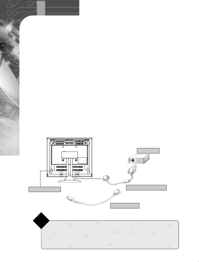
4-1. Monitor Description.
Installation
4
POWER BUTTON
MENU
EXIT
◀
▶AUTO
15-pin D-Sub
Signal Connector
DC Input Connector
Audio Input
6
1. Be sure to turn your monitor, computer and all peripheral devices off
before connection.
2. Connect 15-pin D-Sub connectors to both the computer and monitor.
3. Connect the DC-input terminal to the monitor and power cord to an
approved AC outlet.
4. Turn on your computer and monitor.
5. Turn off your computer and monitor after use.
4-2. Connecting To The Computer
<Note>Self-Diagnostic Screen
Not connecting the monitor with the computer will result in a “No Input Signal,
Check Connection”message on screen. Please insure the monitor is properly
connected if you see this message before calling service.
Note
15pin D-SUB signal cable
DC 12V (output)
15pin D-SUB
DC input connector
7
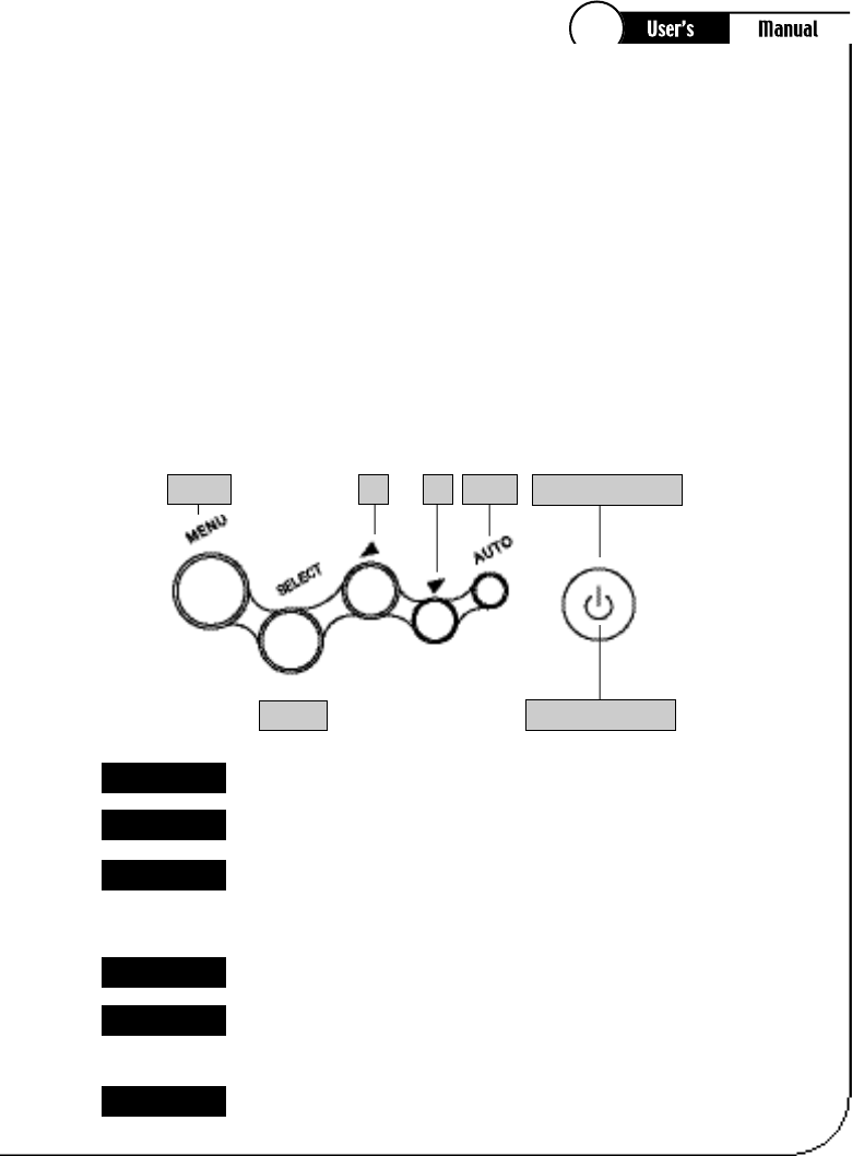
5-1. OSD Menu Description.
Opens the OSD.
Monitor Adjustment
5
OSD Menu
M e n u
SELECT A FUNCTION FROM THE OSD.
S E L E C T
Moves the selector left or right on the OSD
Decreases or increases values if the selected function.
Directly adjust the brightness level if pressed while the OSD is off.
◀/ ▶
Activates the Auto Adjustment function.
A u t o
Indicates the status of the monitor
GREEN : Normal Operation
AMBER Blink : Power Saving Mode or Disconnected Signal Cable.
Power Led
Turns the monitor on and off
Power Button
Your TFT-LCD allows you to easily adjust the characteristics of the image
being displayed.
All of these adjustments are made using the control buttons on the front
of the monitor
While you use these buttons to adjust the controls, an on-screen menu
shows you their numeric values as they change.
POWER BUTTON
POWER LED
MENU ◀ ▶
SELECT
AUTO
8
5-2. Accessing the OSD Menu
1) With the OSD off, push the MENU button to display the main OSD menu.
2) Use the “◀”and “▶”buttons to move between the function icons.
As you move from one icon to another, the function name changes to
reflect the function or group of functions represented by that i con.
3) Press the Select button once to activate the highlighted function then follow
the Tool Tips to select the function and adjust the value
4) After selecting a function, use the “◀”and “▶”buttons to make the adjustments.
The setting sliderbar moves and the numeric value indicator change to reflect
your adjustments.
5) Push the Menu a couple of times to return to the main menu to select another
function or exit from OSD
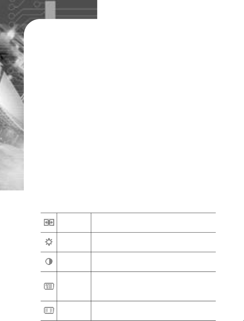
Optimize the display settings for use with computer.
Adjust the brightness of the screen.
Adjust the display to the contrast desired.
Auto Adjust
B r i g h t n e s s
C o n t r a s t
To minimize any vertical bars or stripes visible on
screen background.
The horizontal screen size will also change.
F r e q u e n c y
Adjust the focus of the screen.
P h a s e
5-3. OSD Menu Description
9
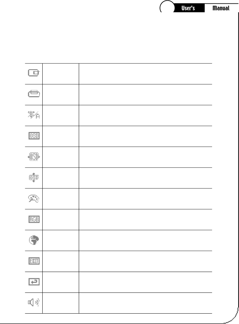
5-3. OSD Menu Description
Adjust the picture image on left and right.
Set the screen on Dos Mode.
Horizontal Position
Dos Mode
Adjust the picture image on up and down.
Vertical Position
Change the transparency of OSD.
OSD Transparence
Move the OSD window to the horizontal direction.
OSD H-Position
Move the OSD window to the vertical direction.
OSD V-Position
Adjust the display color with different set of color
settings.
Color Adjust
Adjust the display color as user's desire.
USER Color
To choose the language in which the control names are
displayed.
OSD Language
To exit from the menu.
E x i t
Discard current settings and replace corresponding
parameters with the factory default values.
Factory Reset
Adjust the built-in speaker volume.
V o l u m e
The following describes in sequence the options in the main menu.

10
5.4 Adjust the screen image
If the “Auto Adjust”does not display proper image, display can be set by manual
adjustment.
1) Type any character on the screen by using notepad or any other word program.
2) Adjust the H/V position for proper display.
3) Use the Frequency option to adjust the image focus.
4) Setup the color, brightness and contrast as you wish to see.
5) Return to normal condition by exit the OSD menu.

11
Specifications
6
LCD Module
●Diagonal : 15.0”inch
●Viewing Image Size : 15.0”inch
●Native Resolution (Pixel Count) : 1024X768
Pixel Pitch
: 0.297 mm
View Angle
:
Typ:65/65 degree (left/right), 50/60 (up/down) (at CR>10)
Display Color
: 16.2M colors (true)
Resolution Supported
: 1024X768 @60Hz-75Hz
800X600 @56Hz-75Hz
640X480 @60Hz-75Hz
720X400 VGA Text
Recommended Resolution
: 1024X768 @60Hz
Horizontal Frequency : 30 - 61 KHz
Vertical Frequency : 55 - 75 Hz
Input Termina
: 15-pin D-Sub Connector.
Voltage Rating
: 12V 3.33A
Power Dissipated
: 40W
Safe Mode Dissipated Power Rating
: Below 5W
Monitor Size
: 347.6 X 373 X 170 mm (W X H X D)
Weight : 4.3 Kg (Unpacked), 5.5 Kg (Packed)
Environmental Considerations
:
●Operating Temperature : 0 ℃~ 35 ℃
●Humidity : 30% ~ 80%
Storage Temperature
:
●Operating Temperature :-5 ℃~ 45 ℃
●Humidity: 5% ~ 90%
6-1. Monitor Specification
12
6-2. Video Input Connector
Pin Number
1
2
3
4
5
6
7
8
9
10
11
12
13
14
15
Signal Name
RED
GREEN
BLUE
N.C
GROUND
RED-GROUND
GREEN-GROUND
BLUE-GROUND
N.C
GROUND
GROUND
DDC Data
H-Sync
V-Sync
DDC Clock
15-pin D-Sub connector is used as the input signal connector.
Pin and input signals are shown in the table below.
13
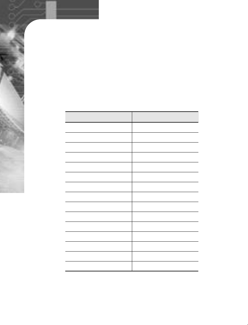
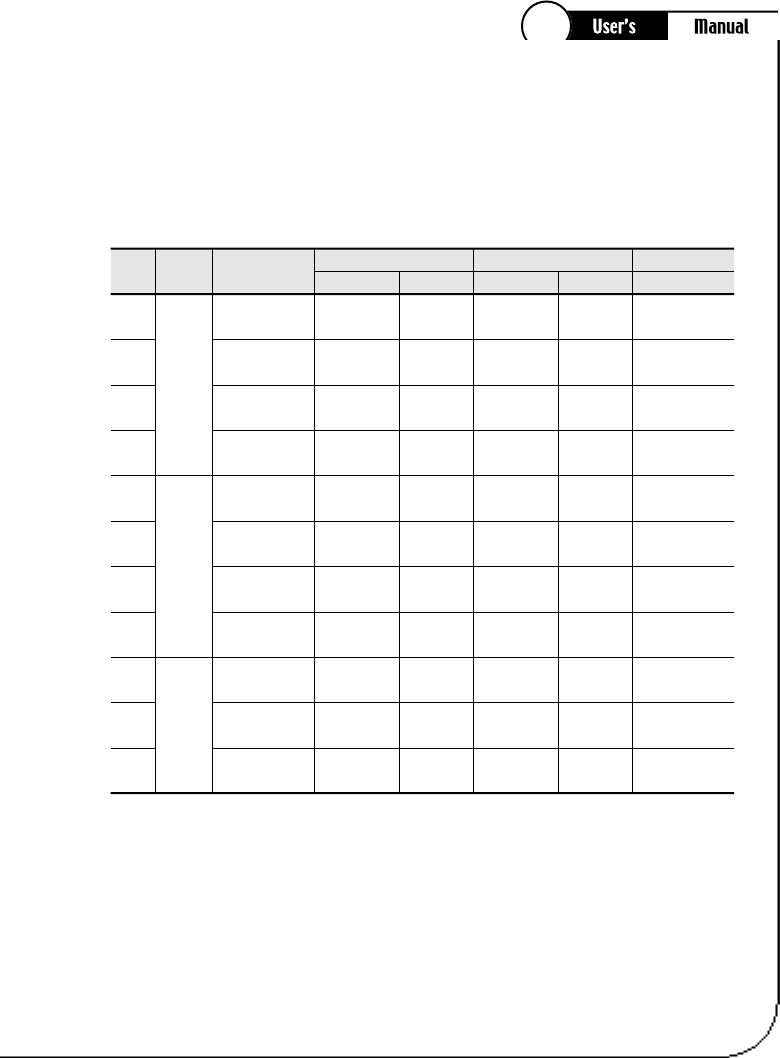
6-3. Resolutions Supported
Horizental
Frequency Polarity
ResolutionModeNo
Vertica
l
Frequency Polarity
Pixel
Clock
(MHz)
2 8 . 3 2 2
2 5 . 1 7 5
3 0 . 2 4 0
3 1 . 5 0 0
3 6 . 0 0 0
4 0 . 0 0 0
5 0 . 0 0 0
4 9 . 5 0 0
6 5 . 0 0 0
7 5 . 0 0 0
7 8 . 7 5 0
P
N
N
N
N / P
P
P
P
N
N
P
N
N
N
N
N / P
P
P
P
N
N
P
3 1 . 4 7 K H z
3 1 . 4 7 K H z
3 5 . 0 0 K H z
3 7 . 8 6 K H z
3 5 . 1 6 K H z
3 7 . 8 8 K H z
4 8 . 0 8 K H z
4 6 . 8 7 K H z
4 8 . 3 6 K H z
5 6 . 4 8 K H z
6 0 . 0 2 K H z
7 2 0×4 0 0
6 4 0×4 8 0
6 4 0×4 8 0
6 4 0×4 8 0
8 0 0×6 0 0
8 0 0×6 0 0
8 0 0×6 0 0
8 0 0×6 0 0
1 0 2 4×7 6 8
1 0 2 4×7 6 8
1 0 2 4×7 6 8
1
2
3
4
5
6
7
8
9
1 0
1 1
V G A
S V G A
X G A
70.0 Hz
60.0 Hz
66.7 Hz
72.8 Hz
56.3 Hz
60.3 Hz
72.2 Hz
75.0 Hz
60.0 Hz
70.1 Hz
75.0 Hz
14
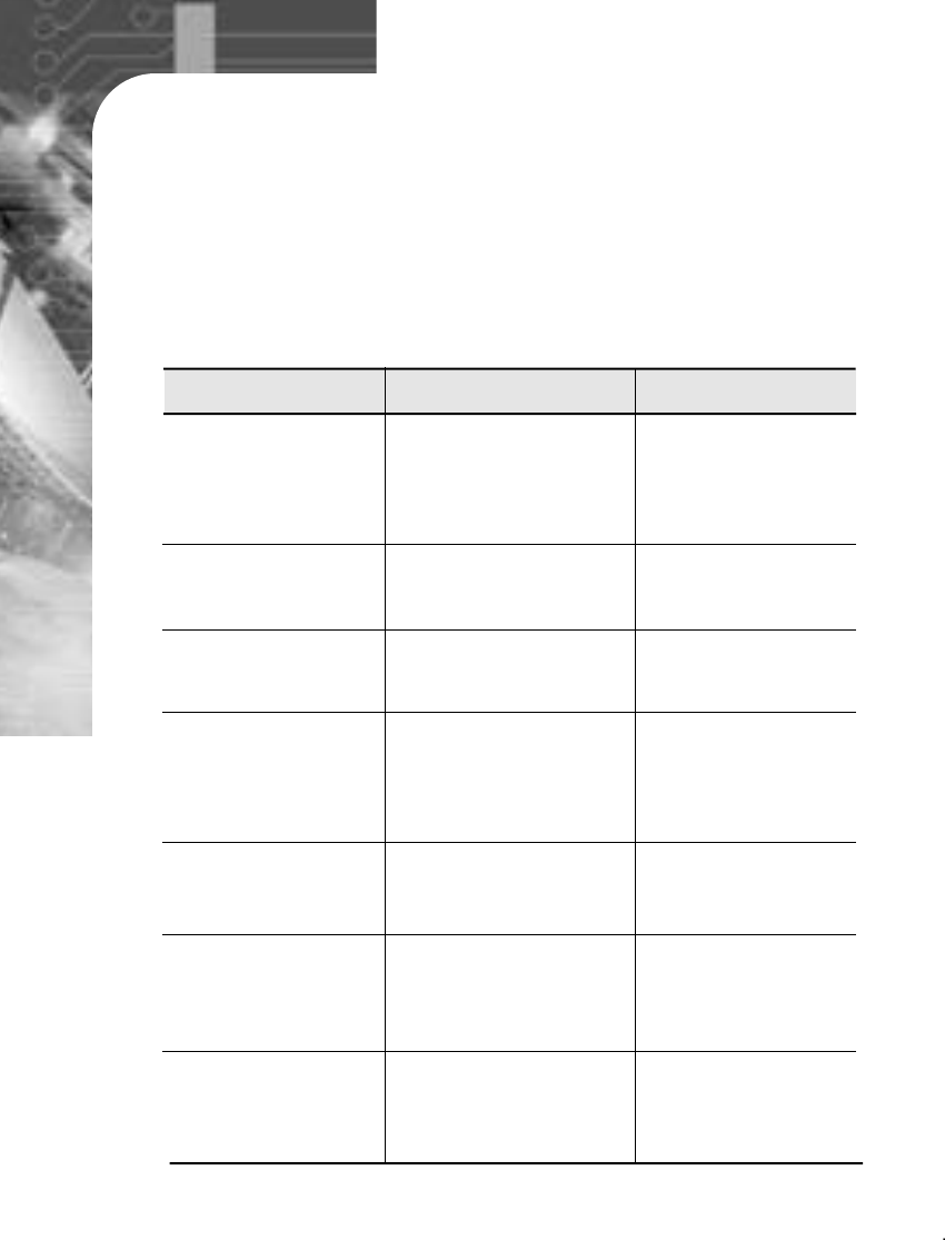
If you have difficulty with the LCD monitor, check the following symptoms
and recommended courses of action.
Troubleshooting
7
Screen Symptom Check point Action
Power LED is “off”,
and no picture?
Power LED is “on”,
but no picture? ▶Brightness or contrast
is adjusted right? Please adjust
brightness and
contrast correctly.
▶Is power cord
connected correctly?
▶Is “No Input Signal
Going to Sleep”
shown on the screen?
▶Please connect
power cord correctly.
▶Please check the
video input terminal.
Screen’s position or
size is not proper? ▶Screen’s position and
size is adjusted
correctly?
Please adjust position
and size correctly.
Screen color is
strange? ▶Your graphic card is
set correctly?
▶Changed resolution is
set correctly?
▶Please check if graphic
card is set correctly.
▶Please check if
changed resolution is set
correctly.
Please reset your
new graphic card
setting.
Please adjust
“Phase”on the OSD
Menu.
Re-configure the
display timeing of
your system.
After changing video
card,color is fixed on
16 color?
Characters on screen
are not focused? Or
horizontal noise
occurred?
Picture at the
CRTmonitor but no
picture at the
LCDmonitor?
▶Windows color setting
is correct?
▶Is “Phase”adjusted
correctly?
▶Is “Out of Range”
shown on the screen?
15
Resolution
Screen resolution is measured in pixels, or picture elements. One pixel
is the smallest area that can be manipulated by the computer.
Resolution is always stated as the horizontal number of pixels by the
vertical number of pixels. A screen displaying 1600 x 1200 pixels has
1200 rows, each 1600 pixels wide.
Descriptions of Technical Te rm s
8
Plug and Play.
Microsoft’s strategy is to be able to install new hardware devices and
configure peripherals easier.
When connecting with computer, the monitor will initially adjust itself
to the best screen settings automatically through its communication
channel, DDC (Display Data Channel)
DDC 1/2B(Display Data Channel 1/2B)
The International Standard VESA DDC method, through which Plug &
Play supported devices can be recognized and connected with the
computer easier. When you turn on the computer’s power, product
information, such as manufacturer, screen size, resolution, timing table,
which is included in monitor circuit board, is transferred to the VGA
Card. (DDC 1/2B) compatibility offers significant performance
advantages by enabling monitor capabilities, including scanning
frequencies and image sizing, to be communicated automatically to the
operating system without the use of drivers or diskettes for installation.
16
Vertical Scan Rate Or Refresh Rate
Number of complete screens displayed per second by the monitor. A 70
Hz refresh rate will provide a flicker-free image. The higher the refresh,
the better the image
Horizontal Scan Rate
Frequency that roughly corresponds to the number of horizontal lines a
monitor can display per second. For 1024 x 768 pixels with a vertical
refresh rate of 75 Hz, the horizontal scan rate is 59.8 KHz.
On-Screen Display (OSD)
Newer, more advanced monitors come equipped with an On-Screen
Display (OSD) that adjusts all display parameters via an on-screen
control panel. OSD allows you to adjust all display set-up parameters
and color temperature settings through icon-based, on-screen control
panels.