Techsphere VP-IIX Hand Vascular Pattern Recognition System User Manual
Techsphere CO., LTD. Hand Vascular Pattern Recognition System
UserManual.wiki
>
Techsphere
>
VP IIX User Manual
User manual
Navigation menu
Upload a User Manual
Namespaces
Wiki Guide
HTML
PDF
Info
Views
User Manual
Discussion / Help
Navigation
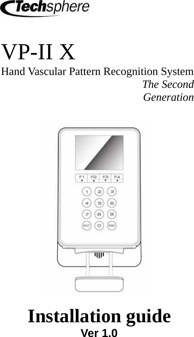

![81.4 VP-II X specification The specifications of VP-II X are as follows: If you have any questions about our product, please contact Techsphere or a local representative. Power voltage AC 100 ~ 250V, 50Hz/60Hz Power consumption 18[W] ( DC 12[V], 1.5[A] ) Host PC interface RS-232 Wiegand input Wiegand 26bits Wiegand output Wiegand 26bits, Wiegand 37bits External system interface RS-232 Server interface Ethernet Other interface External LED signal output Operating temperature -5 ~ 50°C Operating humidity 10% ~ 90% Number of users Depends on the specification of external system Application(Optional) VP-II NetControl-X (Windows 98/2000/XP) SDK (Optional) VP-II SDK(Windows 98/2000/XP)](https://usermanual.wiki/Techsphere/VP-IIX/User-Guide-1046629-Page-8.png)
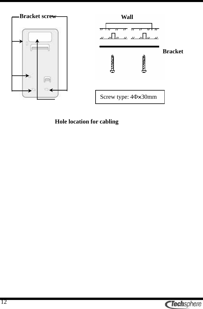
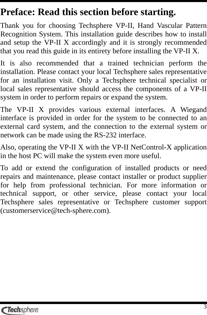
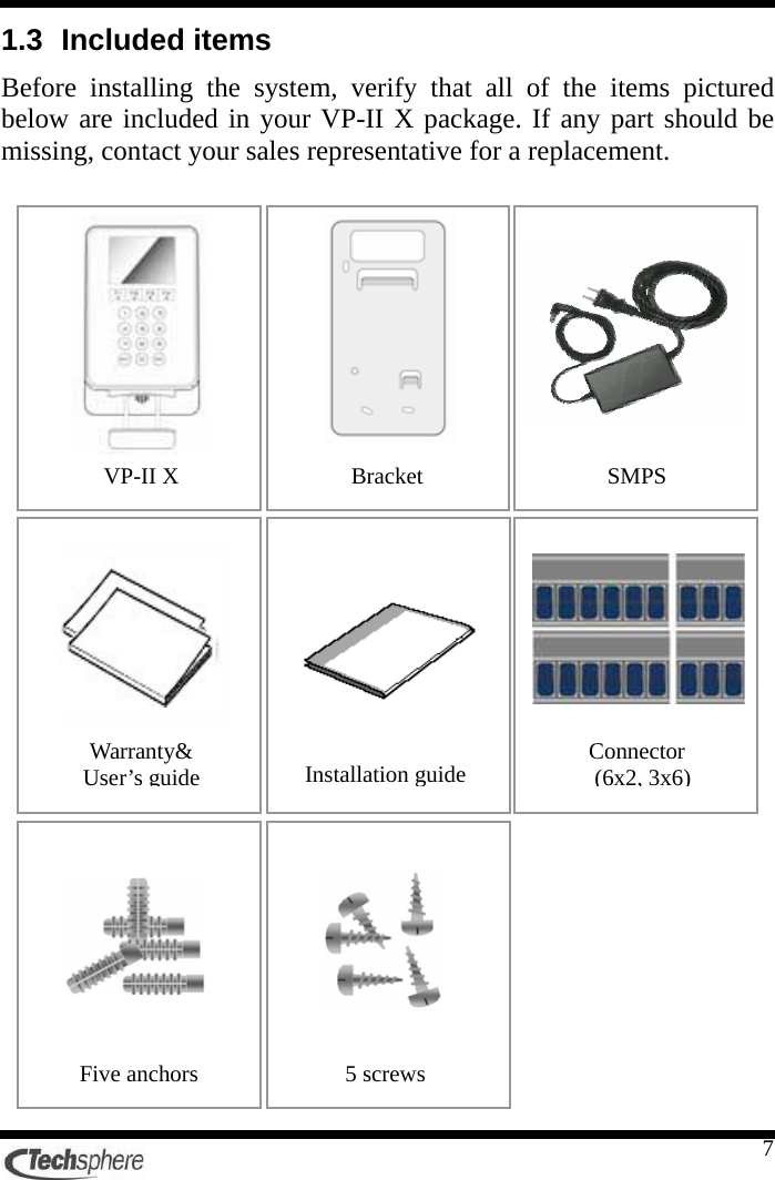
![132.2 VP-II X installation 1. Put the VP-II X on the bracket. [A] 2. Push the VP-II X all the way down with some force from the upper-right part to the lower-left part direction as the VP-II X slides down. If the VP-II X is pushed down only from the upper part to the lower part, the scanner will not be installed properly. [B] 3. When the VP-II X is fixed on the bracket, fix the bracket using the bracket screw located in the sensor module hosing. Bracket screw](https://usermanual.wiki/Techsphere/VP-IIX/User-Guide-1046629-Page-13.png)
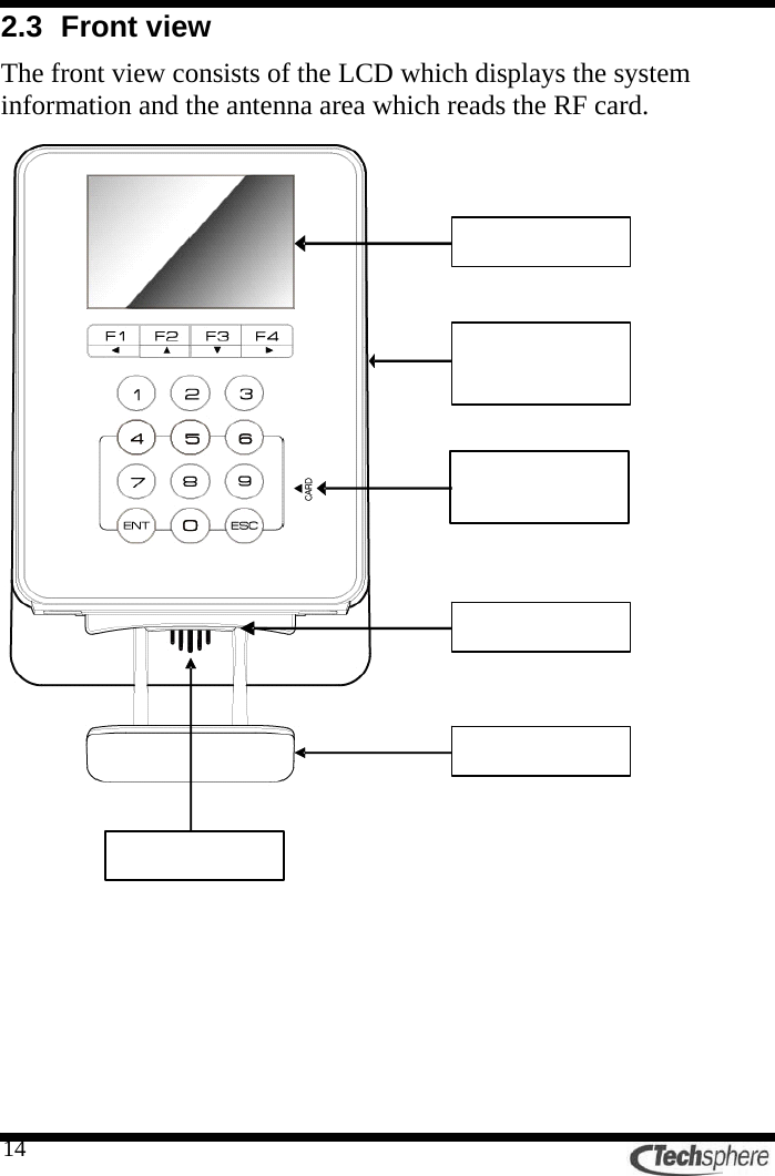
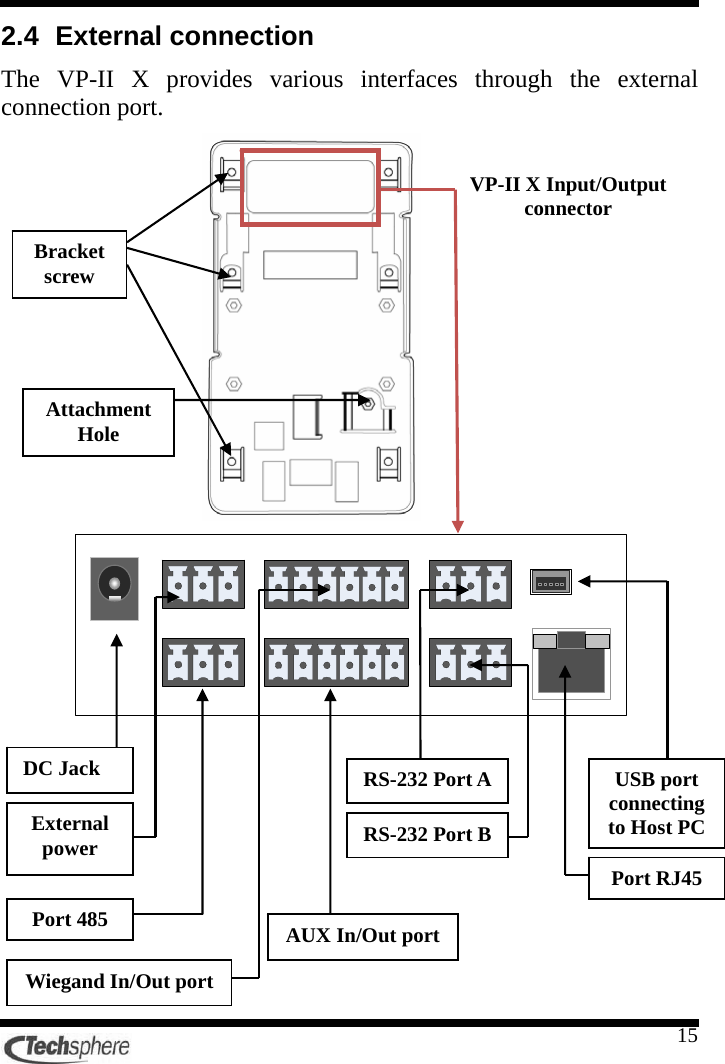
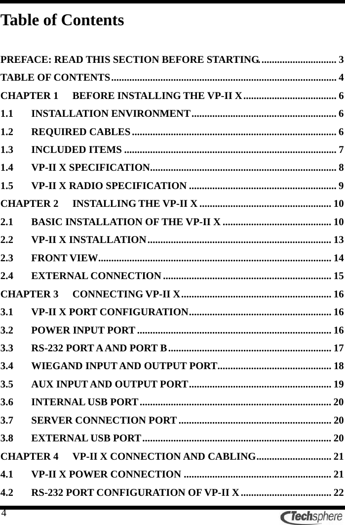
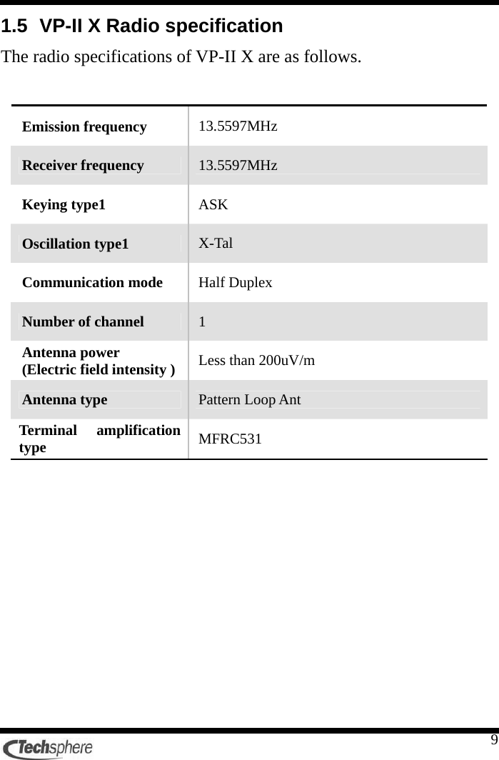
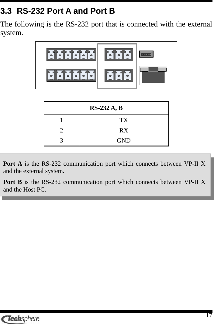
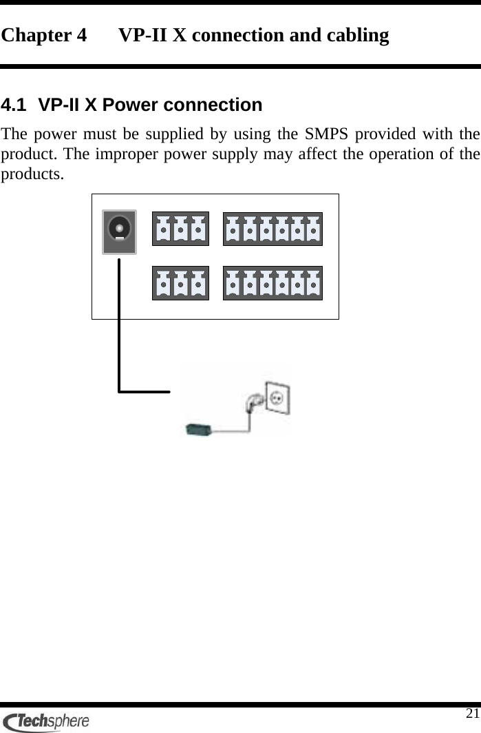
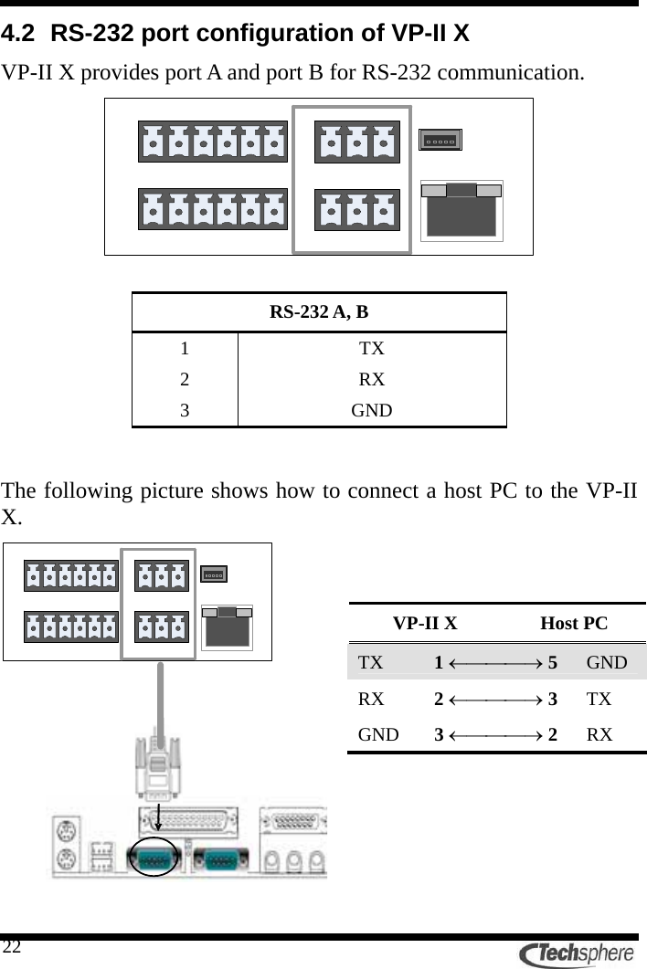
![16Chapter 3 Connecting VP-II X 3.1 VP-II X port configuration VP-II X porvides various external connection port as follows. 3.2 Power input port External power 1 DC +12 [V] 1.5[A] 2 GND 3 GND 123DC Jack External power Port 485 RS-232 Port AAUX In/Out portRS-232 Port BUSB port connecting to Host PC Port RJ45 Wiegand In/Out port](https://usermanual.wiki/Techsphere/VP-IIX/User-Guide-1046629-Page-16.png)
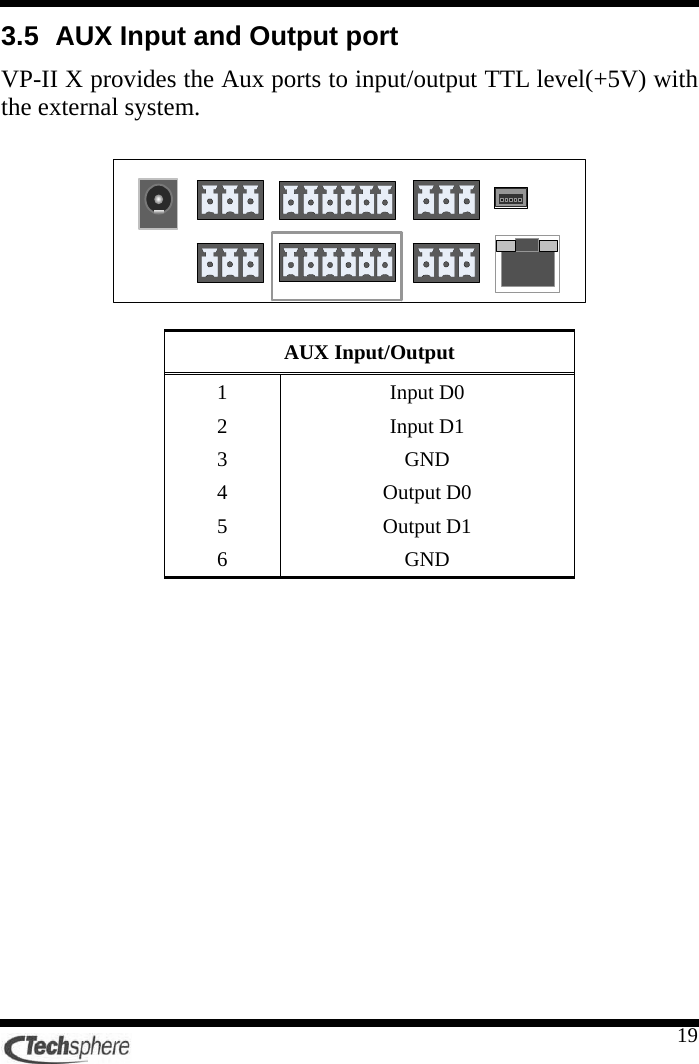
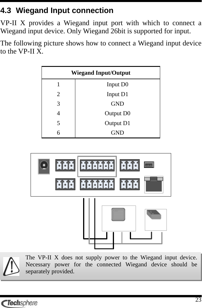
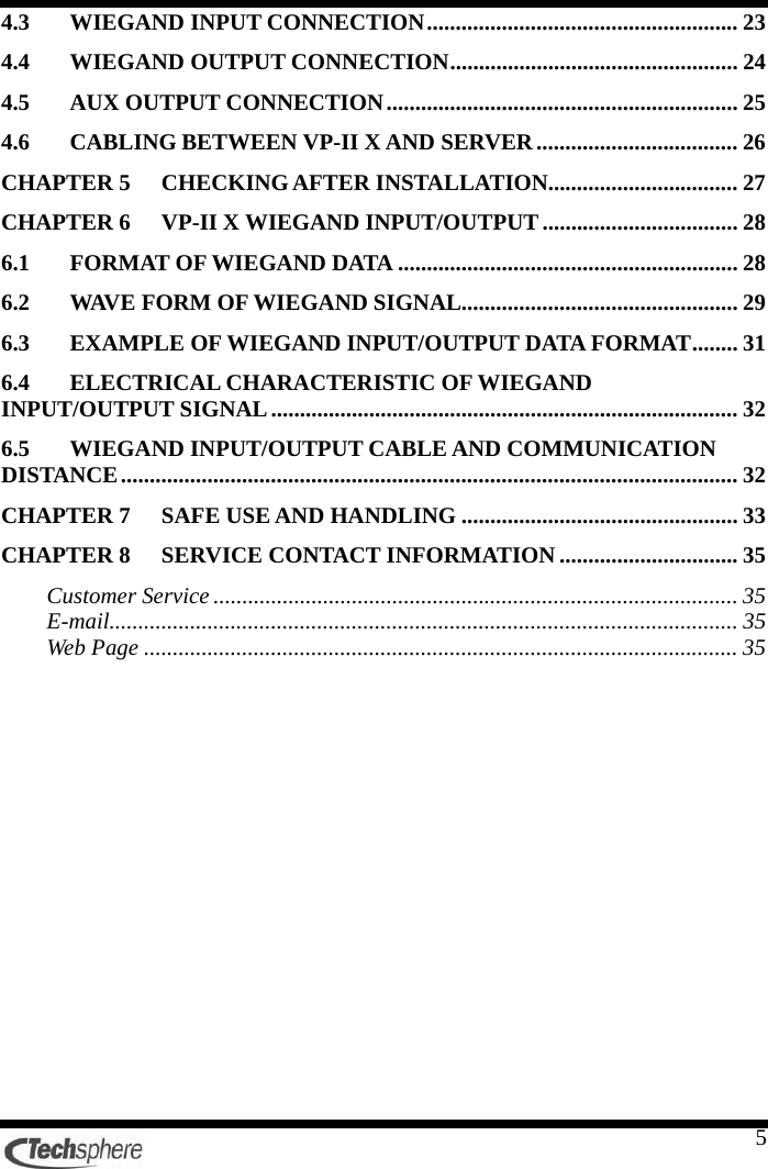
![254.5 AUX output connection The AUX output port can be used to output the signal(+5[V] level output) for the external lamp. Please refer to the VP-II X User’s guide for the port setting method. AUX Input/Output 1 Input D0 2 Input D1 3 GND 4 Output D0 5 Output D1 6 GND](https://usermanual.wiki/Techsphere/VP-IIX/User-Guide-1046629-Page-25.png)
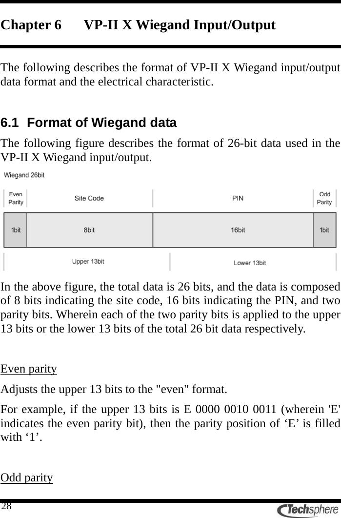
![30Wherein the wave form of the data 0/1 is the combined wave forms of the data 0 and the data 1. In case of the Wiegand signal, the signal occurs classified as data 0 or data 1 according to the value of each bit of the data. If the bit value of the Wiegand data that you want to input/output is ‘0’, then the signal occurs with the data 0, If the data value is ‘1’, then the signal occurs with the data 1. In the above figure, the PWT (pulse width time) and the PIT (pulse interval time) are the times that comprise the signal of one bit in the Wiegand data which is generated with the electrical signal. * Wiegand input PWT(pulse width time) : 20[us] < PWT < 100[us] PIT(pulse interval time) : 200[us] < PIT < 100[ms] * Wiegand output PWT(pulse width time) : 20 ~ 100[us] (Initial value 40[us]) PIT(pulse interval time) : 200[us] ~ 100[ms] (Initial value 2[ms])](https://usermanual.wiki/Techsphere/VP-IIX/User-Guide-1046629-Page-30.png)
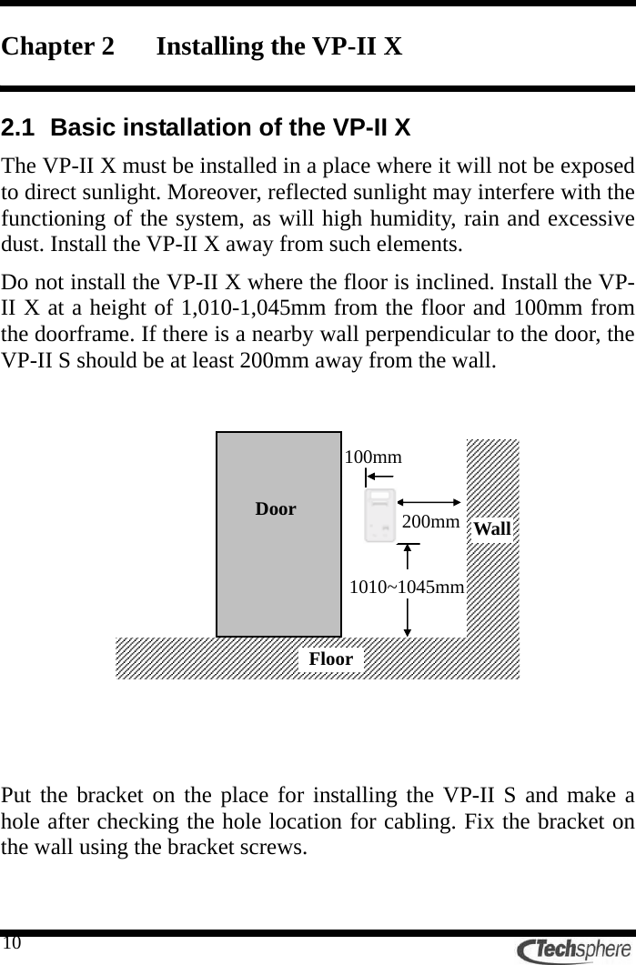
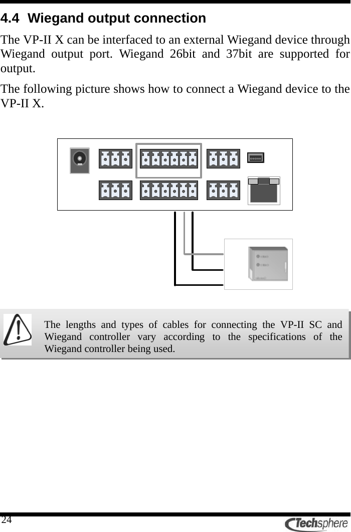
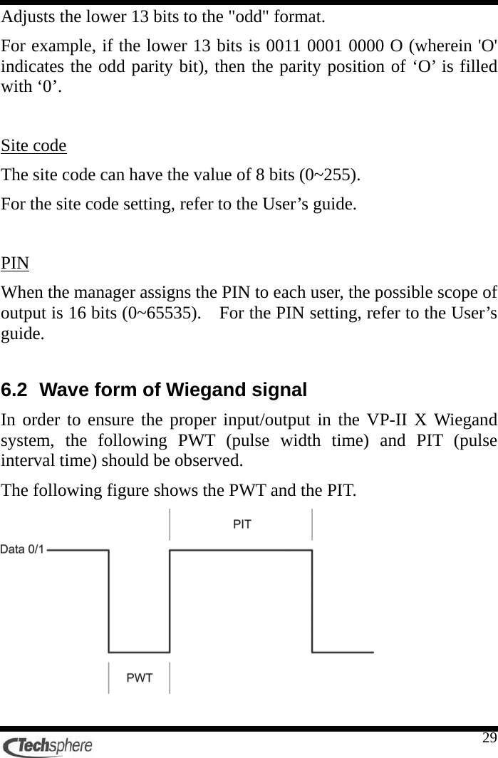
![326.4 Electrical characteristic of Wiegand input/output signal The electrical characteristic of the input/output in the VP-II X Wiegand system is +5[V] at the high level and 0[V] at the low level as shown below. 6.5 Wiegand input/output cable and communication distance The recommended cable is 22AWG which is perfectly shielded or is composed of 5 twisted pairs. The communication distance is 150m (500ft), and the improper cable specifications may cause communication problem.](https://usermanual.wiki/Techsphere/VP-IIX/User-Guide-1046629-Page-32.png)