Techsphere VP-IIX Hand Vascular Pattern Recognition System User Manual
Techsphere CO., LTD. Hand Vascular Pattern Recognition System
User manual

Installation guide
Ver 1.0
VP-II X
Hand Vascular Pattern Recognition System
The Second
Generation

VP-II X Hand Vascular Pattern Recognition System
Installation Guide
Copyright © Techsphere Co., Ltd.
All rights reserved.
Techsphere Co., Ltd. makes no warranty for the use of its products,
assumes no responsibility for any errors that may appear in this
document, and makes no commitment to update the information
contained in this document. Techsphere Co., Ltd. reserves the right to
change or discontinue this product at any time.

3
Preface: Read this section before starting.
Thank you for choosing Techsphere VP-II, Hand Vascular Pattern
Recognition System. This installation guide describes how to install
and setup the VP-II X accordingly and it is strongly recommended
that you read this guide in its entirety before installing the VP-II X.
It is also recommended that a trained technician perform the
installation. Please contact your local Techsphere sales representative
for an installation visit. Only a Techsphere technical specialist or
local sales representative should access the components of a VP-II
system in order to perform repairs or expand the system.
The VP-II X provides various external interfaces. A Wiegand
interface is provided in order for the system to be connected to an
external card system, and the connection to the external system or
network can be made using the RS-232 interface.
Also, operating the VP-II X with the VP-II NetControl-X application
in the host PC will make the system even more useful.
To add or extend the configuration of installed products or need
repairs and maintenance, please contact installer or product supplier
for help from professional technician. For more information or
technical support, or other service, please contact your local
Techsphere sales representative or Techsphere customer support
(customerservice@tech-sphere.com).

4
Table of Contents
PREFACE: READ THIS SECTION BEFORE STARTING.............................. 3
TABLE OF CONTENTS....................................................................................... 4
CHAPTER 1 BEFORE INSTALLING THE VP-II X.................................... 6
1.1 INSTALLATION ENVIRONMENT........................................................ 6
1.2 REQUIRED CABLES............................................................................... 6
1.3 INCLUDED ITEMS .................................................................................. 7
1.4 VP-II X SPECIFICATION........................................................................ 8
1.5 VP-II X RADIO SPECIFICATION ......................................................... 9
CHAPTER 2 INSTALLING THE VP-II X................................................... 10
2.1 BASIC INSTALLATION OF THE VP-II X .......................................... 10
2.2 VP-II X INSTALLATION....................................................................... 13
2.3 FRONT VIEW.......................................................................................... 14
2.4 EXTERNAL CONNECTION................................................................. 15
CHAPTER 3 CONNECTING VP-II X.......................................................... 16
3.1 VP-II X PORT CONFIGURATION....................................................... 16
3.2 POWER INPUT PORT........................................................................... 16
3.3 RS-232 PORT A AND PORT B............................................................... 17
3.4 WIEGAND INPUT AND OUTPUT PORT............................................ 18
3.5 AUX INPUT AND OUTPUT PORT....................................................... 19
3.6 INTERNAL USB PORT.......................................................................... 20
3.7 SERVER CONNECTION PORT ........................................................... 20
3.8 EXTERNAL USB PORT......................................................................... 20
CHAPTER 4 VP-II X CONNECTION AND CABLING............................. 21
4.1 VP-II X POWER CONNECTION ......................................................... 21
4.2 RS-232 PORT CONFIGURATION OF VP-II X................................... 22

5
4.3 WIEGAND INPUT CONNECTION...................................................... 23
4.4 WIEGAND OUTPUT CONNECTION.................................................. 24
4.5 AUX OUTPUT CONNECTION............................................................. 25
4.6 CABLING BETWEEN VP-II X AND SERVER................................... 26
CHAPTER 5 CHECKING AFTER INSTALLATION................................. 27
CHAPTER 6 VP-II X WIEGAND INPUT/OUTPUT.................................. 28
6.1 FORMAT OF WIEGAND DATA ........................................................... 28
6.2 WAVE FORM OF WIEGAND SIGNAL................................................ 29
6.3 EXAMPLE OF WIEGAND INPUT/OUTPUT DATA FORMAT........ 31
6.4 ELECTRICAL CHARACTERISTIC OF WIEGAND
INPUT/OUTPUT SIGNAL................................................................................. 32
6.5 WIEGAND INPUT/OUTPUT CABLE AND COMMUNICATION
DISTANCE........................................................................................................... 32
CHAPTER 7 SAFE USE AND HANDLING ................................................ 33
CHAPTER 8 SERVICE CONTACT INFORMATION ............................... 35
Customer Service ........................................................................................... 35
E-mail............................................................................................................. 35
Web Page ....................................................................................................... 35
6
Chapter 1 Before installing the VP-II X
1.1 Installation environment
The VP-II X should be installed indoors and it is strongly
recommended that no cabling be left exposed when installation is
complete. If concealment of all cables is not possible, the purchaser
of the VP-II system should be informed of this fact before
installation proceeds. Power should be applied only after finishing all
necessary connections. Do not perform any disconnection or
connection during the power is applied to the system. Input power
for VP-II X is AC 100V-250V at 50/60Hz.
1.2 Required cables
The types and thickness of cables used in VP-II S installation should
conform to the specifications in the following table. Failure to use
cables that meet these specifications may result in poor system
performance. In this guide, RS-232 cable connections are depicted as
dotted lines, and UTP cable connections are depicted as two lines.
Cable type Specification 용 도
RS-232 (UL) style 2464-shield
AWG20 4C VP-II X – VP-II XC
LAN
CAT.5 UTP/STP VP-II X - Server
The contents of this guide are subject to change in order to reflect
improvements in product performance. Please leave all setting
ad
j
ustments to an installer or technician.
CAUTION
RISK OF EXPLOSION IF BATTERY IS REPLACED BY AN INCORRECT TYPE.
DISPOSE OF USED BATTERIES ACCORDING TO THE INSTRUCTIONS
7
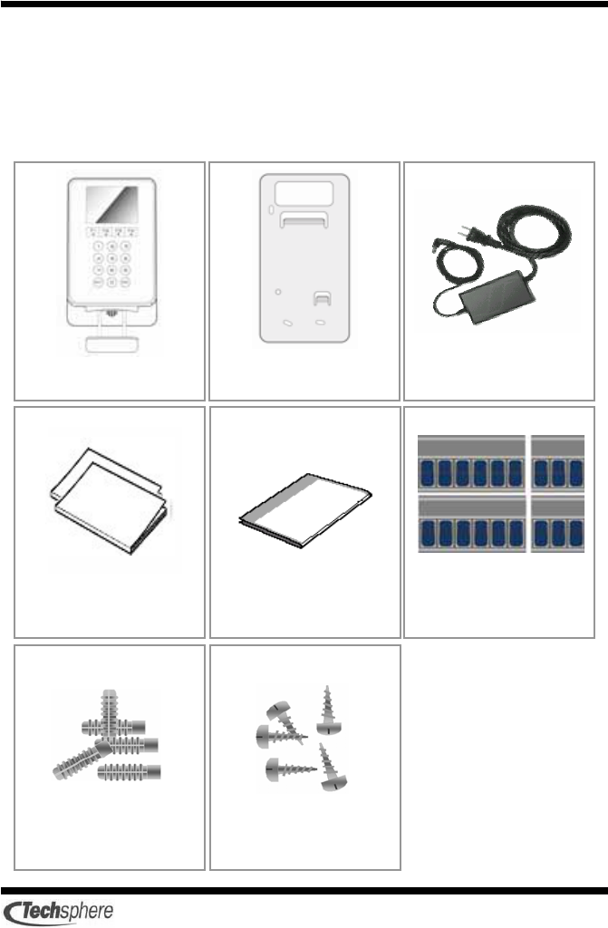
1.3 Included items
Before installing the system, verify that all of the items pictured
below are included in your VP-II X package. If any part should be
missing, contact your sales representative for a replacement.
VP-II X
Bracke
t
SMPS
Warranty&
Use
r’
s
gu
i
de
Installation
g
uide Connector
(
6
x2
,
3
x
6
)
5 screwsFive anchors
8
1.4 VP-II X specification
The specifications of VP-II X are as follows: If you have any
questions about our product, please contact Techsphere or a local
representative.
Power voltage AC 100 ~ 250V, 50Hz/60Hz
Power consumption 18[W] ( DC 12[V], 1.5[A] )
Host PC interface RS-232
Wiegand input Wiegand 26bits
Wiegand output Wiegand 26bits, Wiegand 37bits
External system interface RS-232
Server interface Ethernet
Other interface External LED signal output
Operating temperature -5 ~ 50°C
Operating humidity 10% ~ 90%
Number of users Depends on the specification of external
system
Application(Optional) VP-II NetControl-X (Windows 98/2000/XP)
SDK (Optional) VP-II SDK(Windows 98/2000/XP)
9
1.5 VP-II X Radio specification
The radio specifications of VP-II X are as follows.
Emission frequency 13.5597MHz
Receiver frequency 13.5597MHz
Keying type1 ASK
Oscillation type1 X-Tal
Communication mode Half Duplex
Number of channel 1
Antenna power
(Electric field intensity ) Less than 200uV/m
Antenna type Pattern Loop Ant
Terminal amplification
type MFRC531
10
Chapter 2 Installing the VP-II X
2.1 Basic installation of the VP-II X
The VP-II X must be installed in a place where it will not be exposed
to direct sunlight. Moreover, reflected sunlight may interfere with the
functioning of the system, as will high humidity, rain and excessive
dust. Install the VP-II X away from such elements.
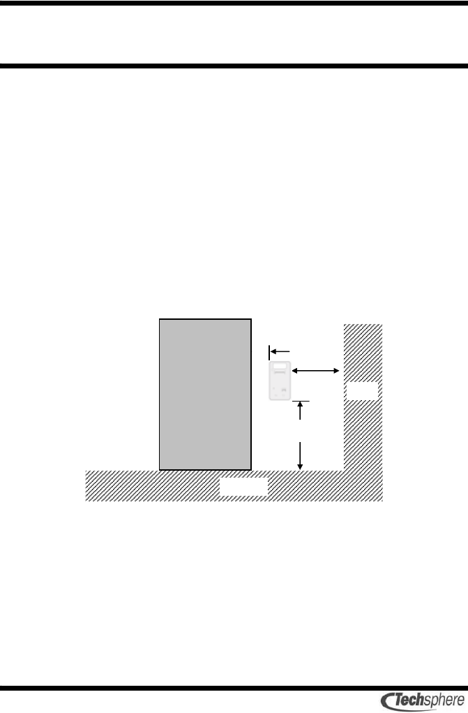
Do not install the VP-II X where the floor is inclined. Install the VP-
II X at a height of 1,010-1,045mm from the floor and 100mm from
the doorframe. If there is a nearby wall perpendicular to the door, the
VP-II S should be at least 200mm away from the wall.
Put the bracket on the place for installing the VP-II S and make a
hole after checking the hole location for cabling. Fix the bracket on
the wall using the bracket screws.
1010~1045m
m
Door
100mm
200mm
Floor
Wall

11
Power must be applied only after finishing all connections. Do not
perform any disconnection or connection after power is applied.
12
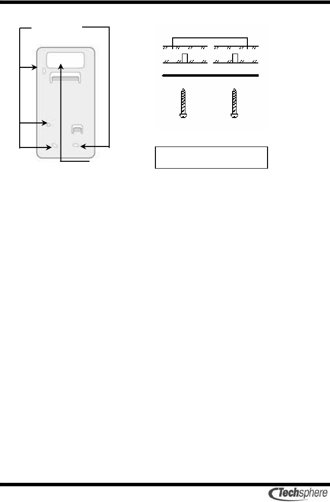
Hole location for cabling
Bracket screw
Bracket
Screw type: 4
Φ
×
30mm
Wall
13
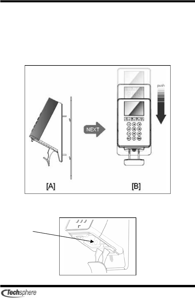
2.2 VP-II X installation
1. Put the VP-II X on the bracket. [A]
2. Push the VP-II X all the way down with some force from the
upper-right part to the lower-left part direction as the VP-II X slides
down. If the VP-II X is pushed down only from the upper part to the
lower part, the scanner will not be installed properly. [B]
3. When the VP-II X is fixed on the bracket, fix the bracket using the
bracket screw located in the sensor module hosing.
Bracket
screw
14
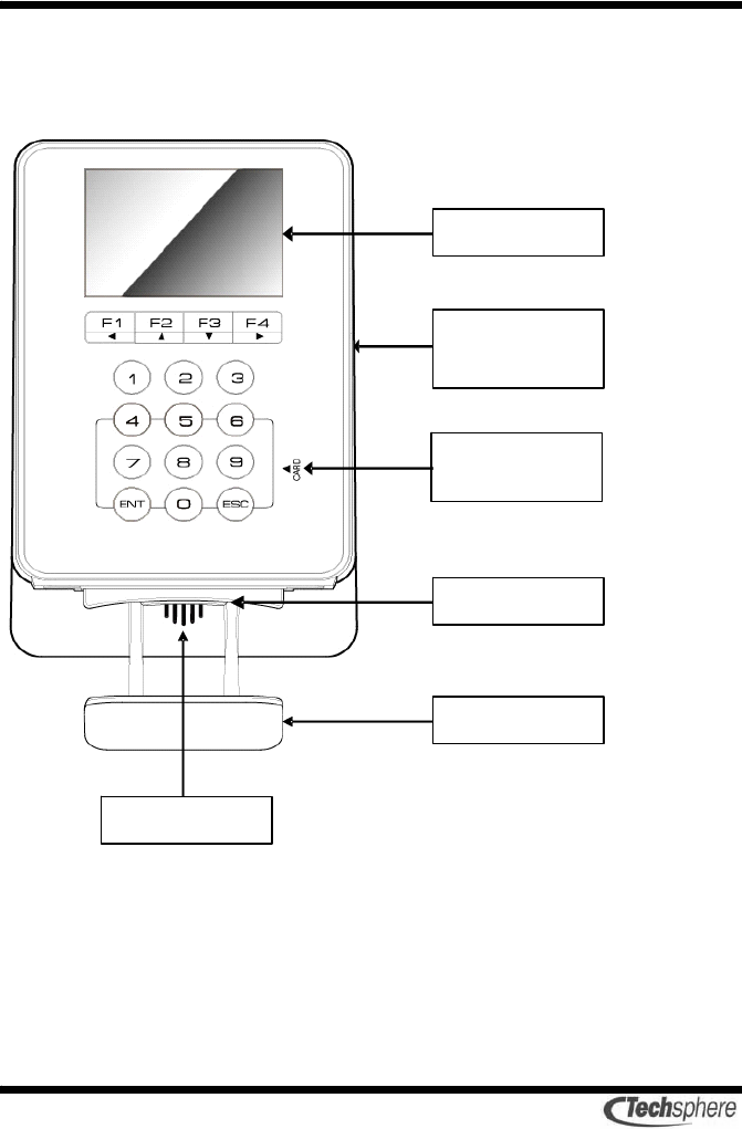
2.3 Front view
The front view consists of the LCD which displays the system
information and the antenna area which reads the RF card.
15
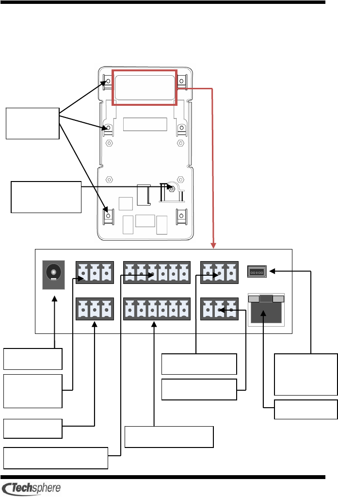
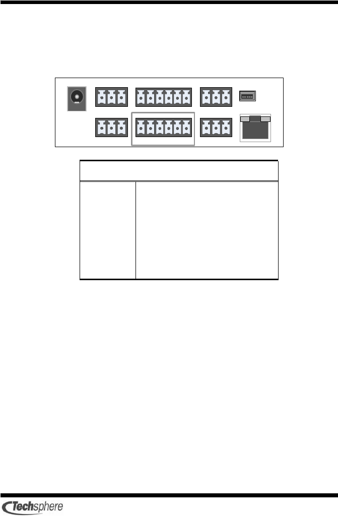
2.4 External connection
The VP-II X provides various interfaces through the external
connection port.
VP-II X Input/Output
connector
Attachment
Hole
Bracket
screw
Wiegand In/Out port
DC Jack
External
power
Port 485
RS-232 Port A
AUX In/Out port
RS-232 Port B
USB port
connecting
to Host PC
Port RJ45
16
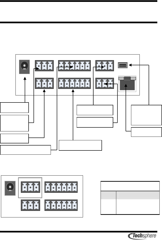
Chapter 3 Connecting VP-II X
3.1 VP-II X port configuration
VP-II X porvides various external connection port as follows.
3.2 Power input port
External power
1 DC +12 [V] 1.5[A]
2 GND
3 GND
123
DC Jack
External
power
Port 485
RS-232 Port A
AUX In/Out port
RS-232 Port B
USB port
connecting
to Host PC
Port RJ45
Wiegand In/Out port
17
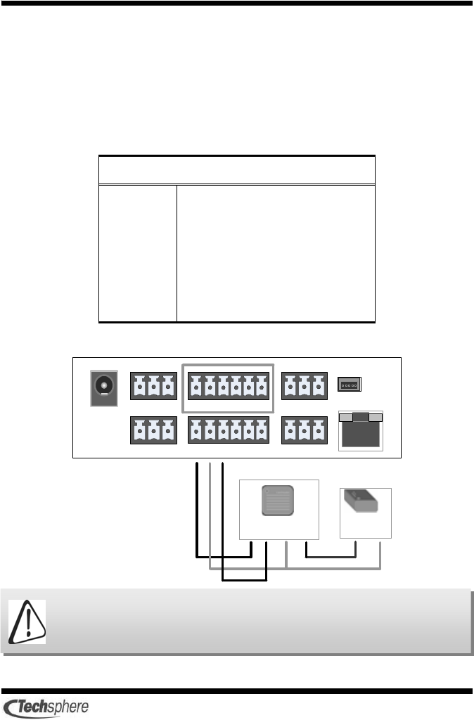
3.3 RS-232 Port A and Port B
The following is the RS-232 port that is connected with the external
system.
RS-232 A, B
1 TX
2 RX
3 GND
Port A is the RS-232 communication port which connects between VP-II X
and the external system.
Port B is the RS-232 communication port which connects between VP-II X
and the Host PC.
18
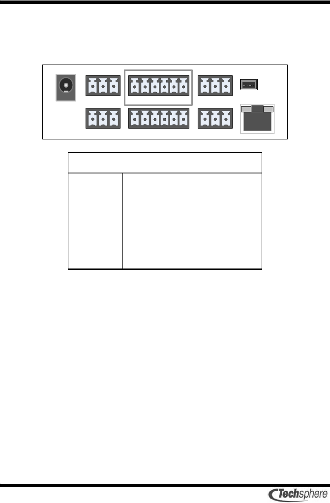
3.4 Wiegand Input and Output port
VP-II S supports the input (Wiegand 26 bits) and the output
(Wiegand 37 bits) through the Wiegand port.
Wiegand Input/Output
1 Input D0
2 Input D1
3 GND
4 Output D0
5 Output D1
6 GND
19
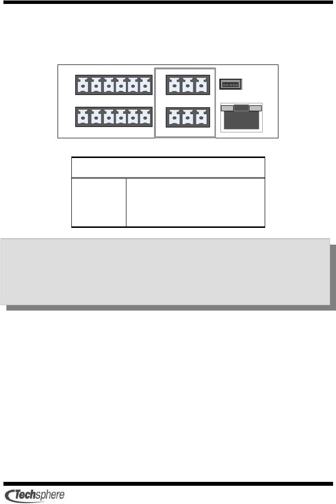
3.5 AUX Input and Output port
VP-II X provides the Aux ports to input/output TTL level(+5V) with
the external system.
AUX Input/Output
1 Input D0
2 Input D1
3 GND
4 Output D0
5 Output D1
6 GND
20
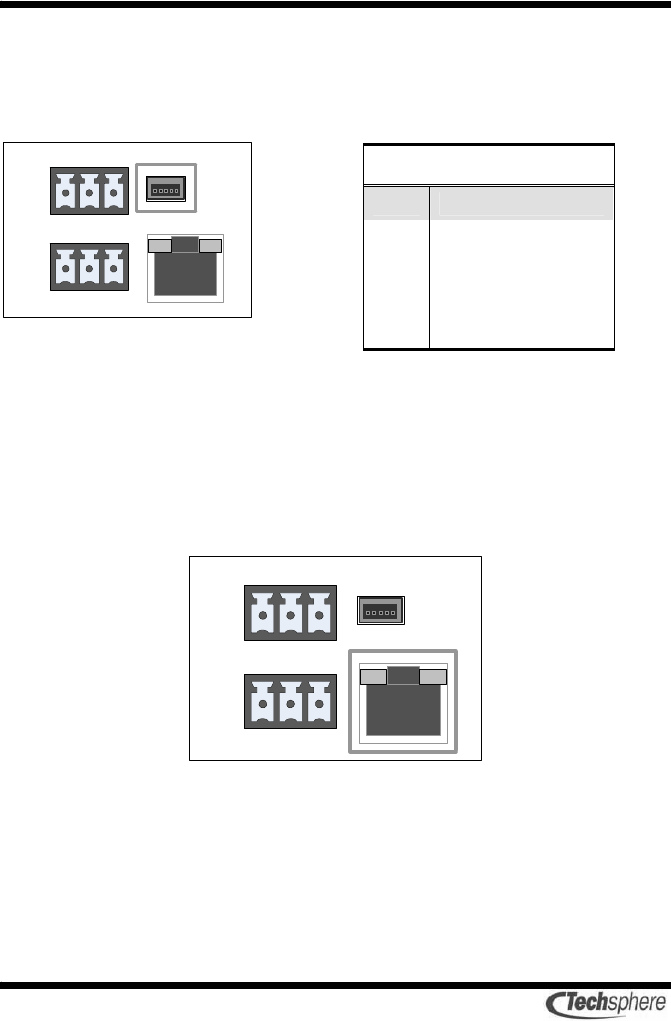
3.6 Internal USB port
The following port is necessary for the production process or the
maintenance use.
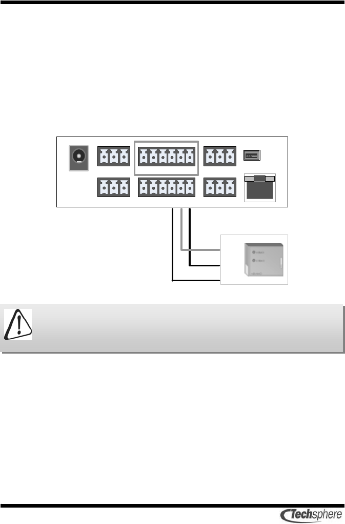
3.7 Server connection port
VP-II X provides the LAN port to connect the server.
The Cable must conform the CAT.5 UTP/STP standard and the
maximum length should be within100m.
3.8 External USB port
The USB port placing on the left of VP-II X is necessary for the
maintenance use.
External power
1 VBUS
2 D-
3 D+
4 N.C.
5 GND
21
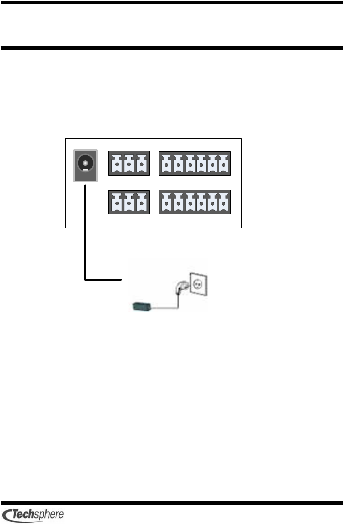
Chapter 4 VP-II X connection and cabling
4.1 VP-II X Power connection
The power must be supplied by using the SMPS provided with the
product. The improper power supply may affect the operation of the
products.
22
4.2 RS-232 port configuration of VP-II X
VP-II X provides port A and port B for RS-232 communication.
RS-232 A, B
1 TX
2 RX
3 GND
The following picture shows how to connect a host PC to the VP-II
X.
VP-II X Host PC
TX 1 ←⎯⎯⎯→ 5 GND
RX 2 ←⎯⎯⎯→ 3 TX
GND 3 ←⎯⎯⎯→ 2 RX
23
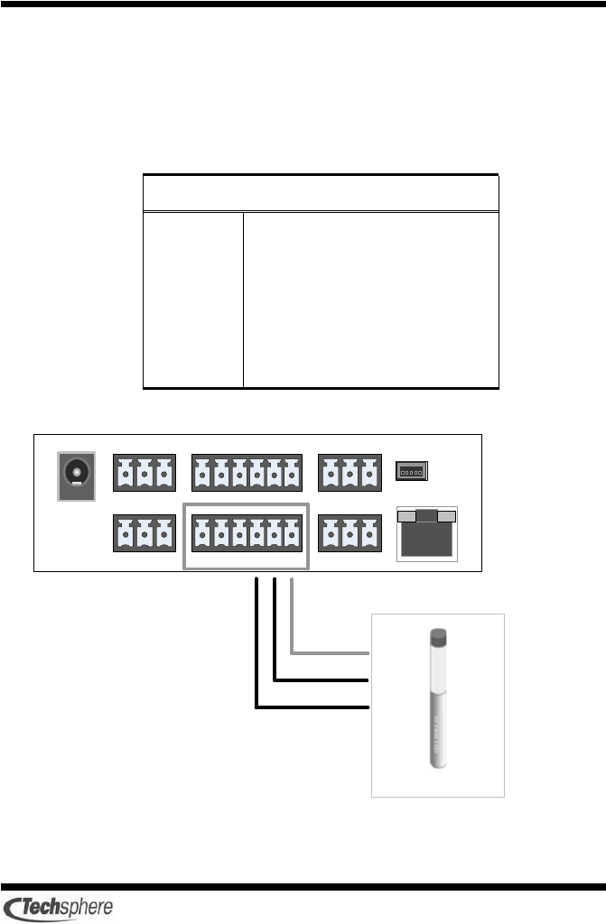
4.3 Wiegand Input connection
VP-II X provides a Wiegand input port with which to connect a
Wiegand input device. Only Wiegand 26bit is supported for input.
The following picture shows how to connect a Wiegand input device
to the VP-II X.
Wiegand Input/Output
1 Input D0
2 Input D1
3 GND
4 Output D0
5 Output D1
6 GND
The VP-II X does not supply power to the Wiegand input device.
Necessary power for the connected Wiegand device should be
separately provided.
24
4.4 Wiegand output connection
The VP-II X can be interfaced to an external Wiegand device through
Wiegand output port. Wiegand 26bit and 37bit are supported for
output.
The following picture shows how to connect a Wiegand device to the
VP-II X.
The lengths and types of cables for connecting the VP-II SC and
Wiegand controller vary according to the specifications of the
Wiegand controller being used.
25
4.5 AUX output connection
The AUX output port can be used to output the signal(+5[V] level
output) for the external lamp.
Please refer to the VP-II X User’s guide for the port setting method.
AUX Input/Output
1 Input D0
2 Input D1
3 GND
4 Output D0
5 Output D1
6 GND
26
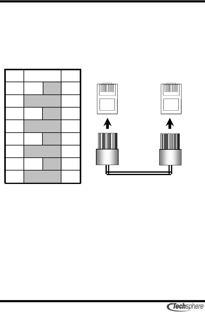
4.6 Cabling between VP-II X and server
Cable connecting the VP-II SC to the server is CAT.5 UTP/STP
standard cables; the RJ-45 connectors are used.
To prepare a connection cable, apply connection in a straight-through
manner between the two RJ-45 connectors as follows.
8 brown 8
7
brown
white
7
6
blue 6
5
blue white
5
4
green 4
3
green white
3
2 orange 2
1
orange
white
1
P2 Cable color P1 18 18
18 18
RJ-45
Connecto
r
UTP cable

27
Chapter 5 Checking after installation
After finishing the installation, perform the following steps in order
to ensure correct operations of the VP-II X.
① Check the cables to ensure that it is connected as instructed in
accordance with the installation guide.
② Confirm the power connection.
③ After look through the VP-II X User’s guide, operate the VP-II X
accordingly.
④ Confirm whether the verification performance is normal.
⑤ If the system is connected to a door lock, confirm the door lock
functions after the verification whether it is operated normally as
intended.
⑥ If the system is connected to a host PC, check the
communication status after setting up the program.
⑦ If the communication is normal, confirm whether the data is
normally saved after user enrollment and verification.
28
Chapter 6 VP-II X Wiegand Input/Output
The following describes the format of VP-II X Wiegand input/output
data format and the electrical characteristic.
6.1 Format of Wiegand data
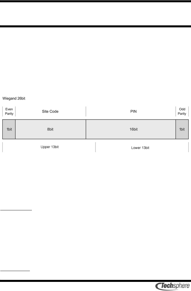
The following figure describes the format of 26-bit data used in the
VP-II X Wiegand input/output.
In the above figure, the total data is 26 bits, and the data is composed
of 8 bits indicating the site code, 16 bits indicating the PIN, and two
parity bits. Wherein each of the two parity bits is applied to the upper
13 bits or the lower 13 bits of the total 26 bit data respectively.
Even parity
Adjusts the upper 13 bits to the "even" format.
For example, if the upper 13 bits is E 0000 0010 0011 (wherein 'E'
indicates the even parity bit), then the parity position of ‘E’ is filled
with ‘1’.
Odd parity
29
Adjusts the lower 13 bits to the "odd" format.
For example, if the lower 13 bits is 0011 0001 0000 O (wherein 'O'
indicates the odd parity bit), then the parity position of ‘O’ is filled
with ‘0’.
Site code
The site code can have the value of 8 bits (0~255).
For the site code setting, refer to the User’s guide.
PIN
When the manager assigns the PIN to each user, the possible scope of
output is 16 bits (0~65535). For the PIN setting, refer to the User’s
guide.
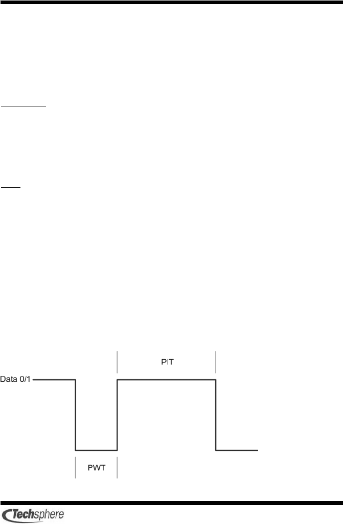
6.2 Wave form of Wiegand signal
In order to ensure the proper input/output in the VP-II X Wiegand
system, the following PWT (pulse width time) and PIT (pulse
interval time) should be observed.
The following figure shows the PWT and the PIT.

30
Wherein the wave form of the data 0/1 is the combined wave forms
of the data 0 and the data 1.
In case of the Wiegand signal, the signal occurs classified as data 0
or data 1 according to the value of each bit of the data.
If the bit value of the Wiegand data that you want to input/output is
‘0’, then the signal occurs with the data 0,
If the data value is ‘1’, then the signal occurs with the data 1.
In the above figure, the PWT (pulse width time) and the PIT (pulse
interval time) are the times that comprise the signal of one bit in the
Wiegand data which is generated with the electrical signal.
* Wiegand input
PWT(pulse width time) : 20[us] < PWT < 100[us]
PIT(pulse interval time) : 200[us] < PIT < 100[ms]
* Wiegand output
PWT(pulse width time) : 20 ~ 100[us] (Initial value 40[us])
PIT(pulse interval time) : 200[us] ~ 100[ms] (Initial value 2[ms])
31
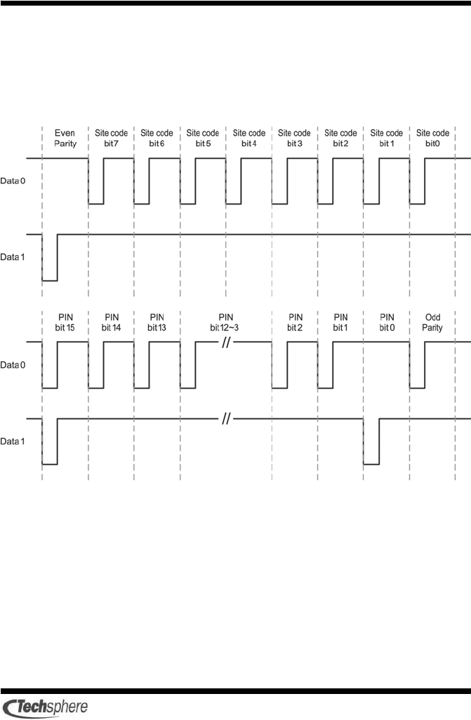
6.3 Example of Wiegand input/output data format
The following figure shows the format of the Wiegand input/output
data when the site code value is ‘001’ and the PIN is '01’ in the
Wiegand 26-bit system.
32
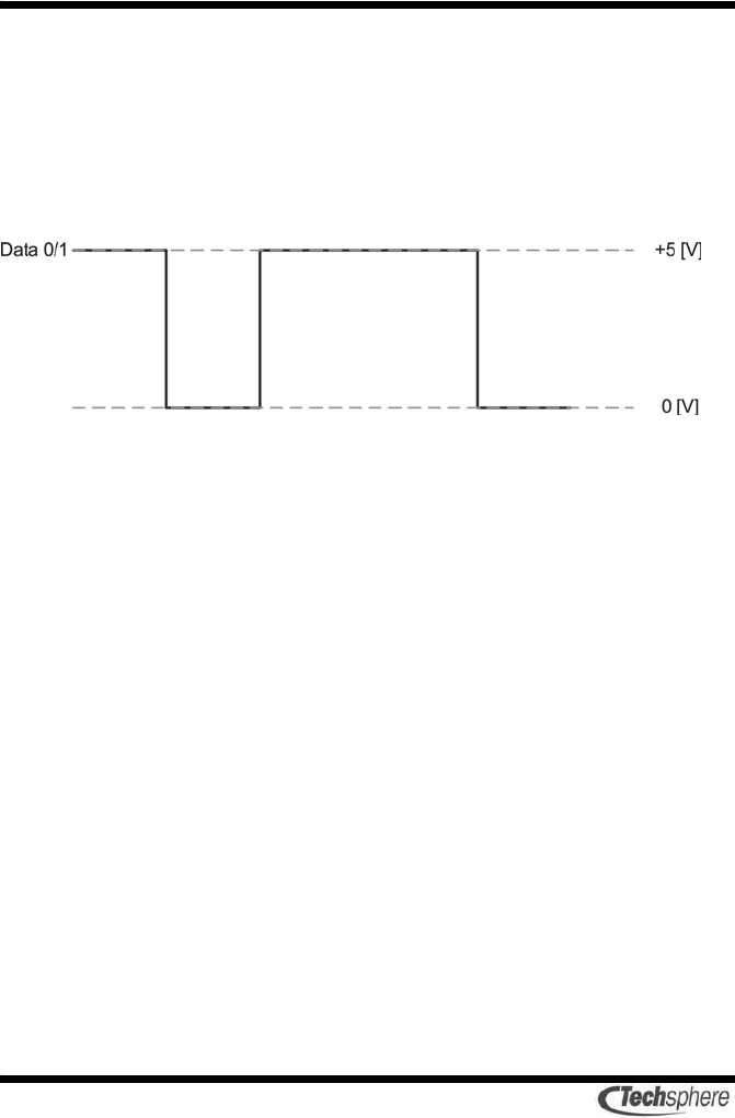
6.4 Electrical characteristic of Wiegand input/output
signal
The electrical characteristic of the input/output in the VP-II X
Wiegand system is +5[V] at the high level and 0[V] at the low level
as shown below.
6.5 Wiegand input/output cable and communication
distance
The recommended cable is 22AWG which is perfectly shielded or is
composed of 5 twisted pairs. The communication distance is 150m
(500ft), and the improper cable specifications may cause
communication problem.
33
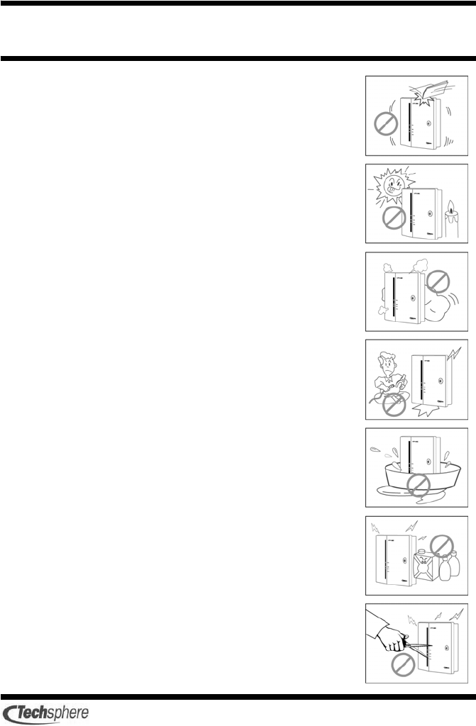
Chapter 7 Safe use and handling
Avoid strong impacts, shocks, or vibrations to components of
the VP-II X, since these actions may cause the components to
fail.
Install the VP-II X in a location that is not exposed to direct
sunlight. Exposure to sunlight may cause verification failures
by saturating the Scanner or damage by overheating of system
components.
To prevent electric shock and fire, immediately switch off the
power to the system and contact your Techsphere local sale
representative if any component of the VP-II X emits smoke or
unusual odors.
Do not disassemble, repair, or modify the VP-II X. Contact
your Techsphere local sale representative for such work.
Do not install the VP-II X in an area where humidity is very
high or where the system will be exposed to rain or dust.
Exposure to excess water or dust may cause electric shock or
fire.
Do not clean the VP-II X by directly spraying it with water. Do
not use benzene, thinner, alcohol or other volatile chemicals to
clean the system.
Do not insert objects such as chopsticks, wires, or drills into
the ventilation holes of the system. Especially do not insert
metallic objects into the system..

34

35
Chapter 8 Service contact information
Customer Service
Do not open components of VP-II systems in order to perform
repairs or to expand the system. A Techsphere technical specialist or
local sales representative should be contacted for system repairs and
hardware expansion.
Please do not hesitate to contact Techsphere and your local
Techsphere sales representative. We can help with any matter relating
to the evaluation, purchase, and use of VP-II Hand Vascular Pattern
Recognition systems, including
9 General information
9 Order procedure
9 Shipping process
9 Technical support
9 Guarantee support
9 Determining your optimal system settings
E-mail
sales@tech-sphere.com
customerservice@tech-sphere.com
Web Page
http://www.tech-sphere.com

36
FCC Compliance Statement
For Class B digital device
INFORMATION TO THE USER
This equipment has been tested and found to comply with the limits for a
Class B digital device, pursuant to part 15 of the FCC Rules. These limits
are designed to provide reasonable protection against harmful interference
in a residential installation. This equipment generates, uses and can
radiate radio frequency energy and, if not installed and used in
accordance with the instructions, may cause harmful interference to radio
communications. However, there is no guarantee that interference will not
occur in a particular installation. If this equipment does cause harmful
interference to radio or television reception, which can be determined by
turning the equipment off and on, the user is encouraged to try to correct
the interference by one or more of the following measures: ·
- Reorient or relocate the receiving antenna.
- Increase the separation between the equipment and receiver.
- Connect the equipment into an outlet on a circuit different from that to
which the receiver is connected.
- Consult the dealer or an experienced radio/TV technician for help.
WARNING
Any changes or modifications not expressly approved by the
manufacturer could void user’s authority to operate the equipment.
CE Compliance Statement
This product was tested by ONETECH, Inc. and found to comply with all
the requirements of the EMC Directive 89/336/EEC as amended.
The equipment complies with the standards;
z EN 55 022: 1998 + A1: 2000 + A2: 2003(Class B)
z EN 50 130-4: 1995 + A1: 1998 +A2: 2003
z EN 61 000-3-2: 2000
z EN 61 000-3-3: 1995 + A1: 2001

http://www.tech-sphere.com http://www.tech-sphere.com http://www.tech-sphere.com http://www.tech-sphere.com
37
Memo

Wonil B/D, 980-54 Bangbae
Seocho, Seoul, Korea 137-060
TEL:+82.2.523.4715 Fax:+82.2.523.4765