Tecniplast S p A ACBOXRX02 Reception and Remote transmission of Alarm Signals User Manual Remote Alarm System
Tecniplast S.p.A. Reception and Remote transmission of Alarm Signals Remote Alarm System
UserManual.wiki
>
Tecniplast S p A
>
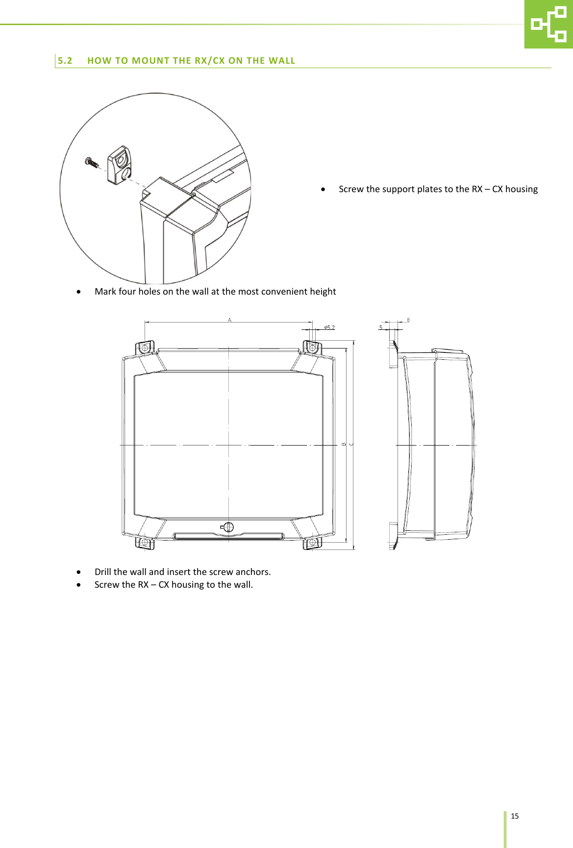
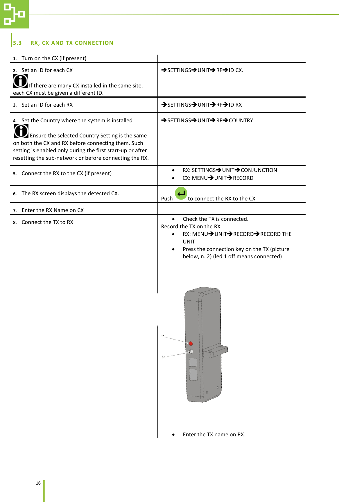
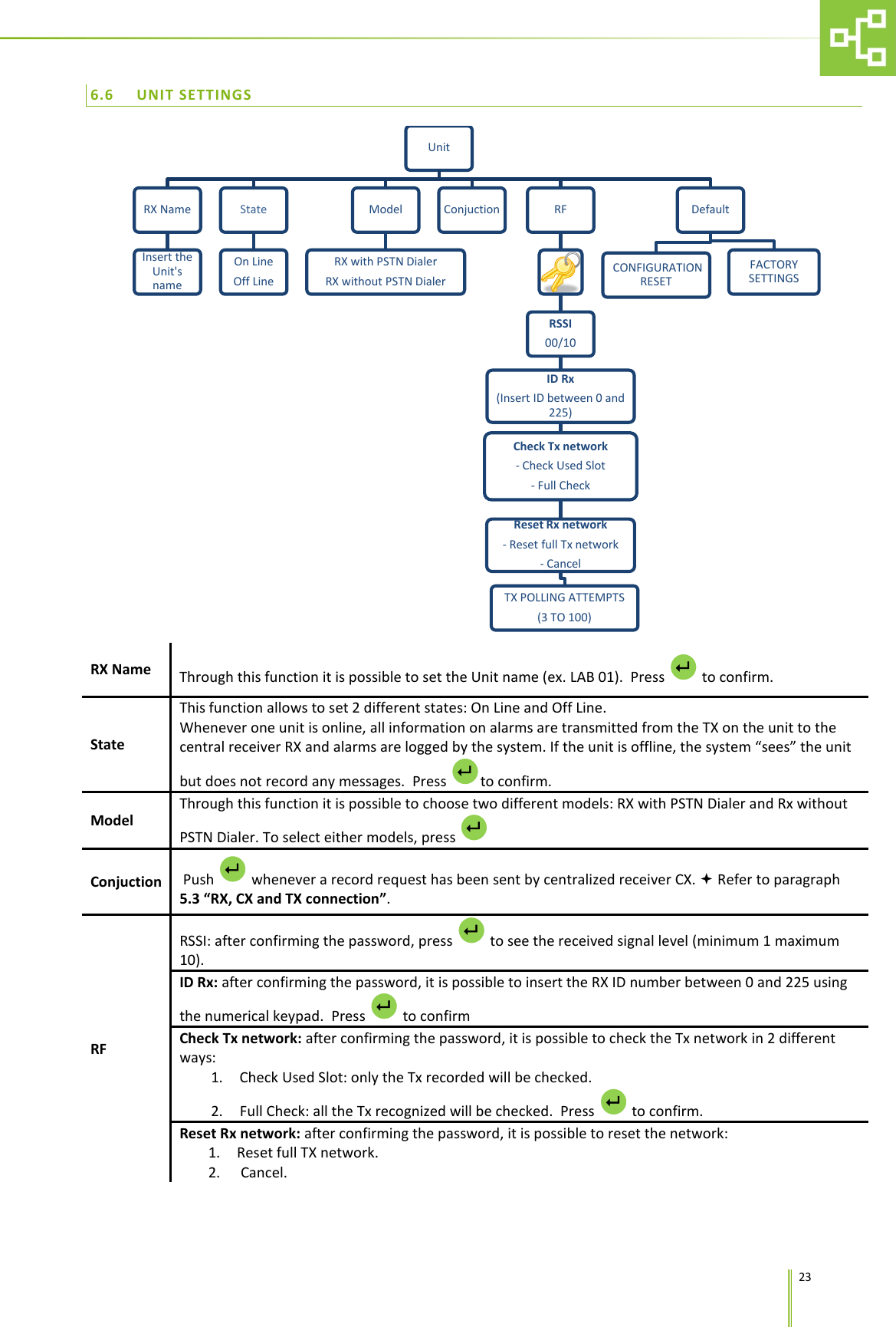
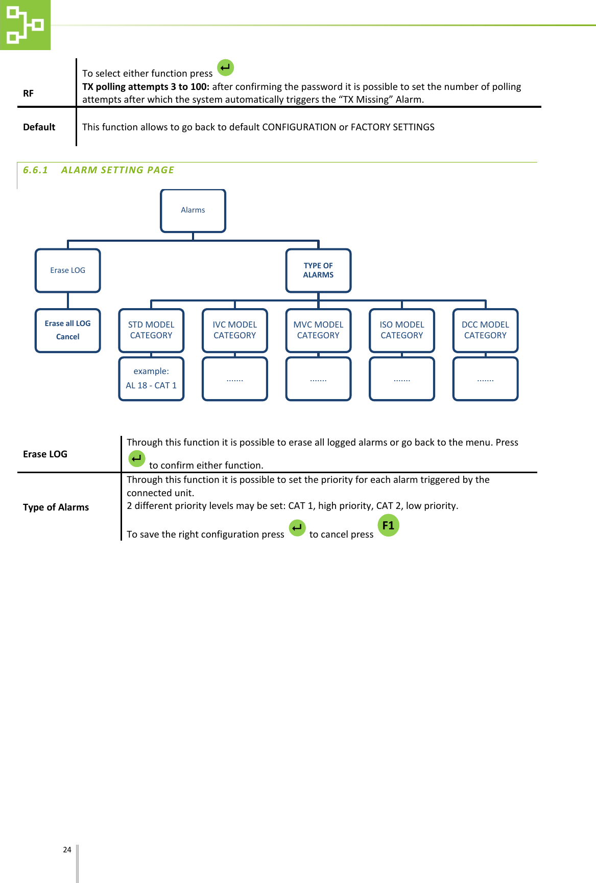
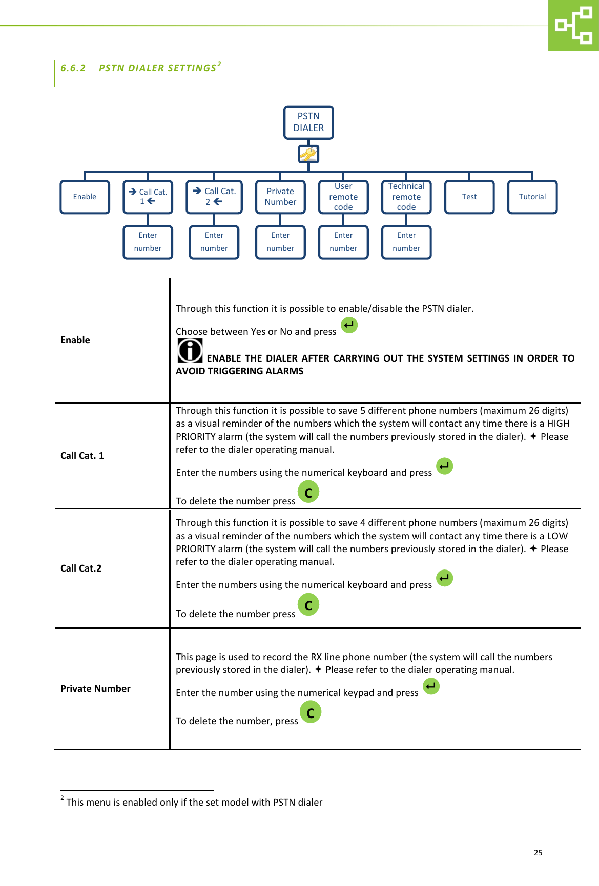
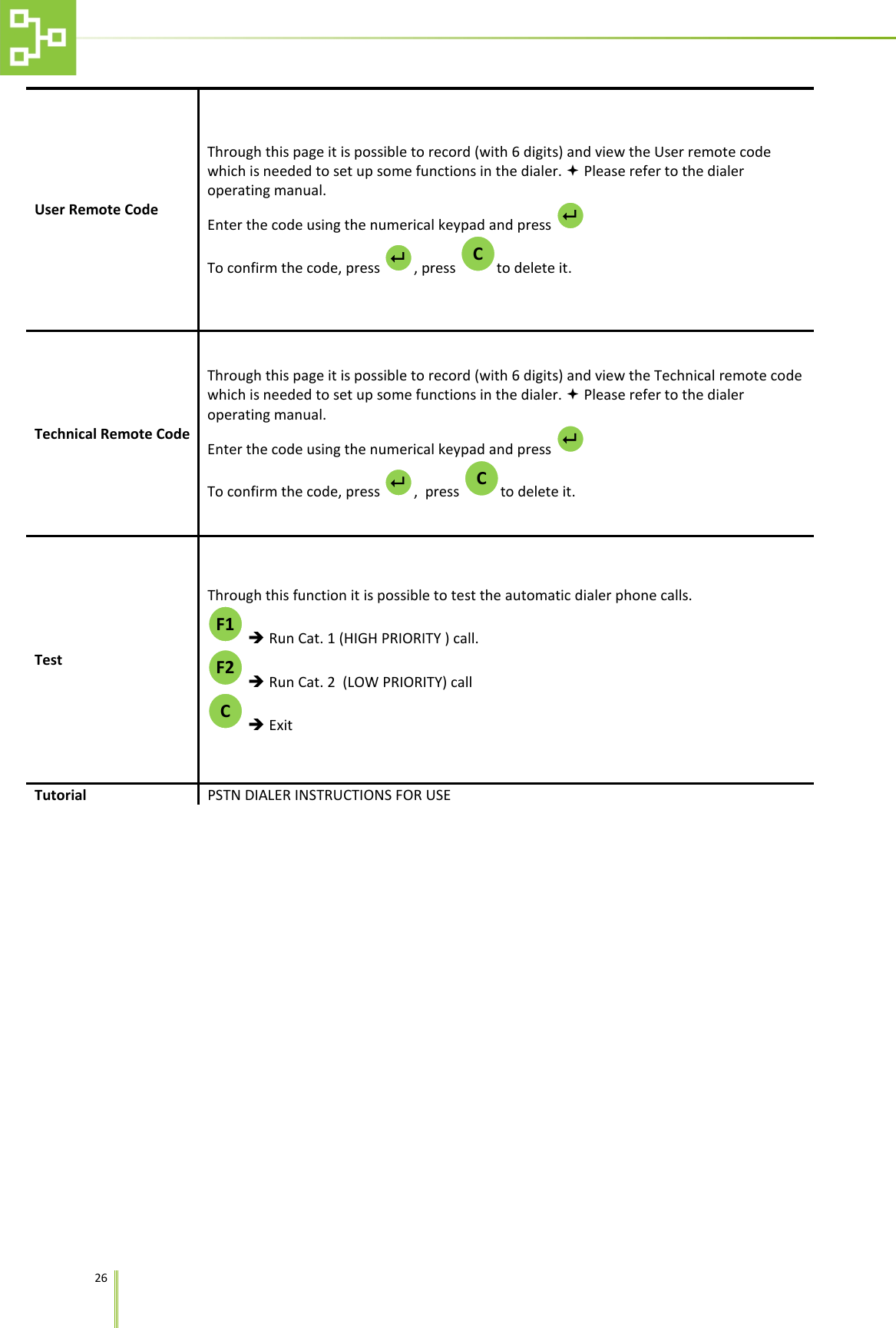
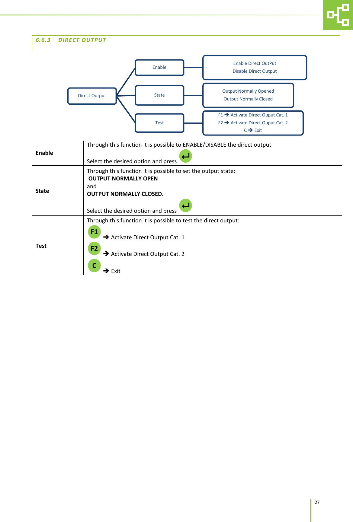
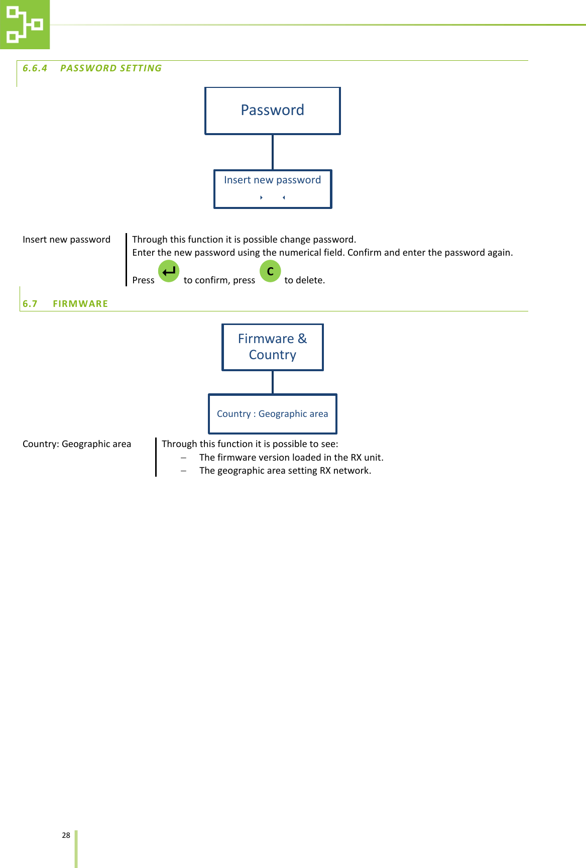
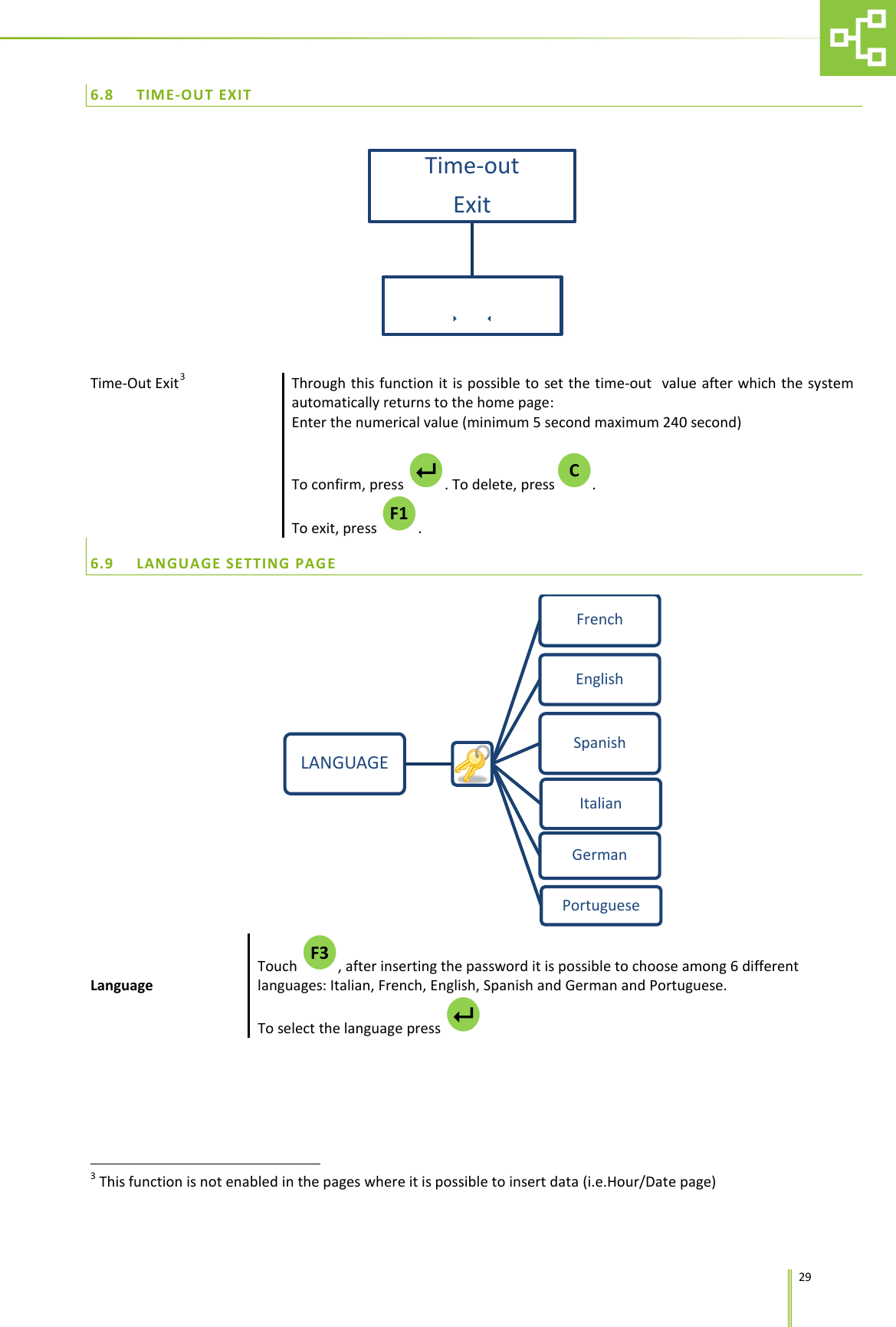
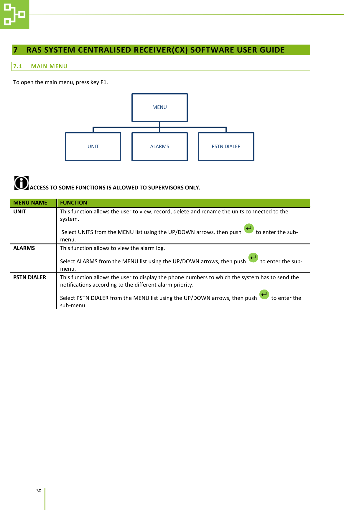
ACBOXRX02 User Manual
User Manual
Navigation menu
Upload a User Manual
Namespaces
Wiki Guide
HTML
PDF
Info
Views
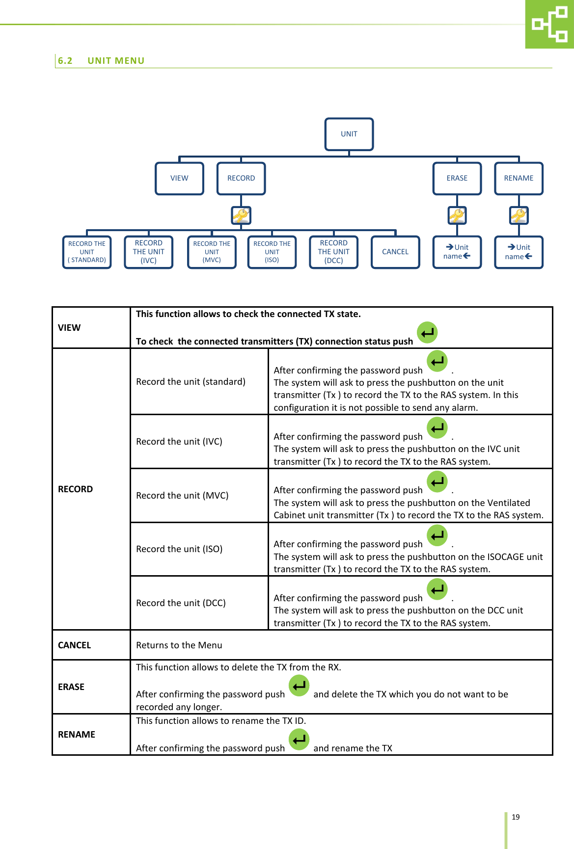
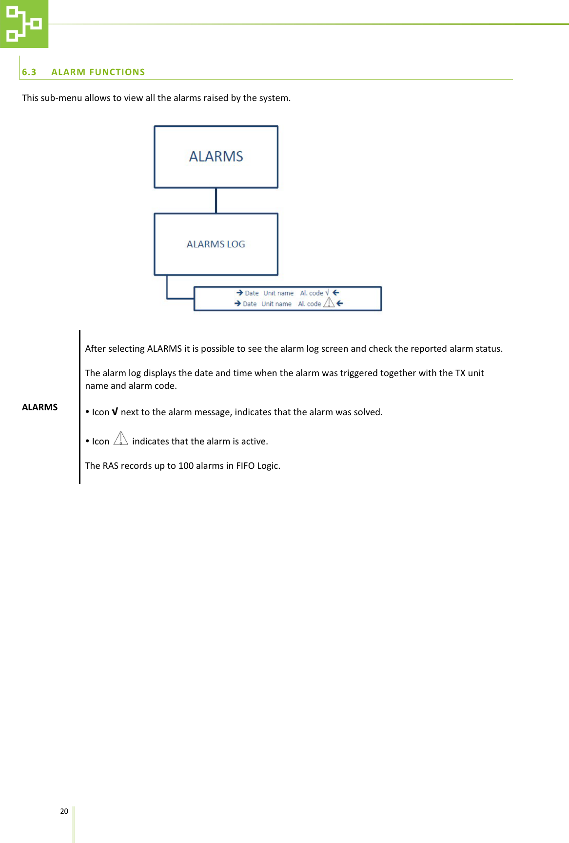
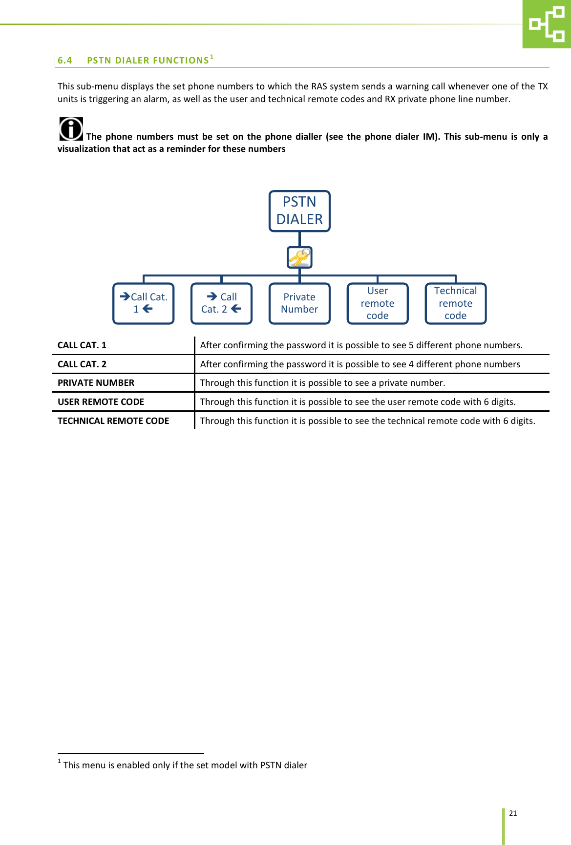
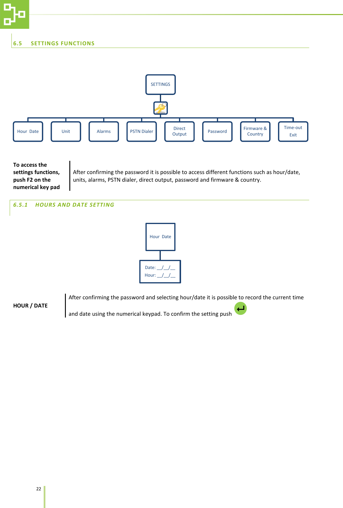
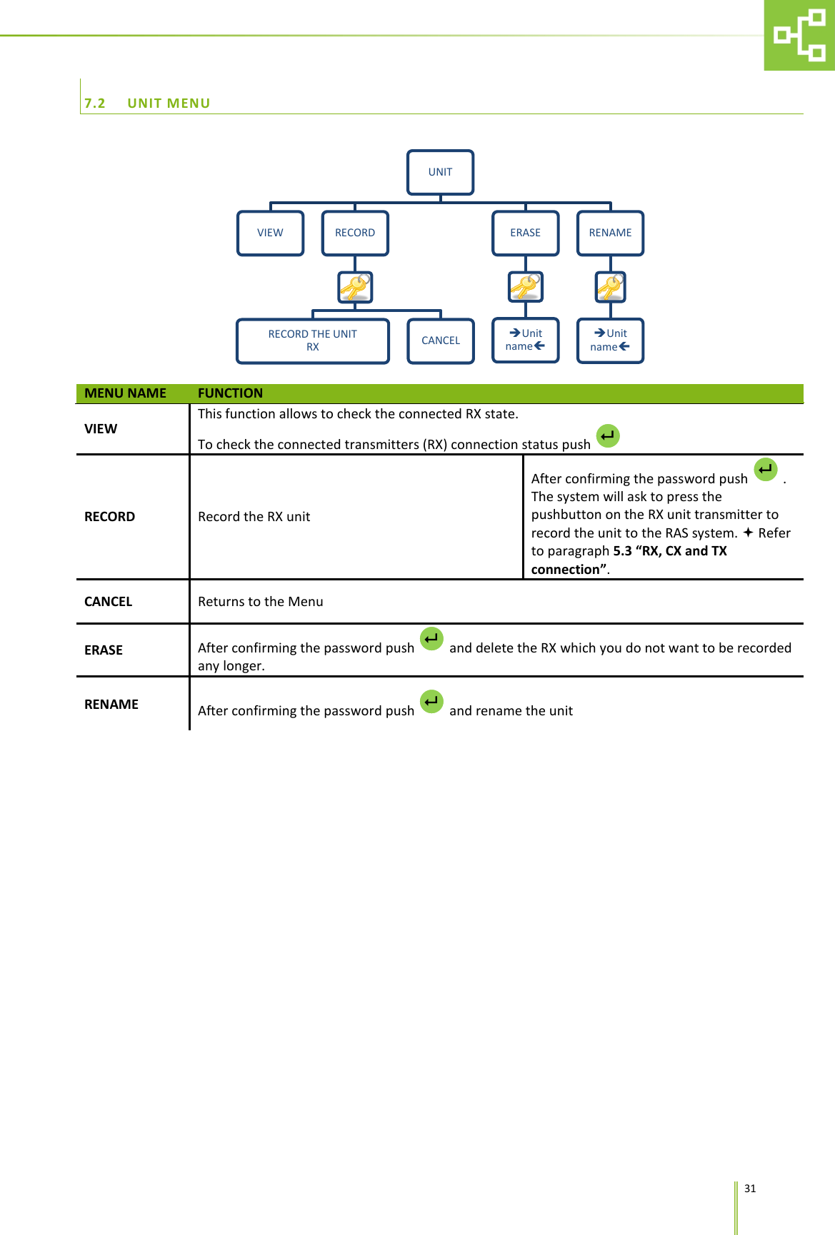
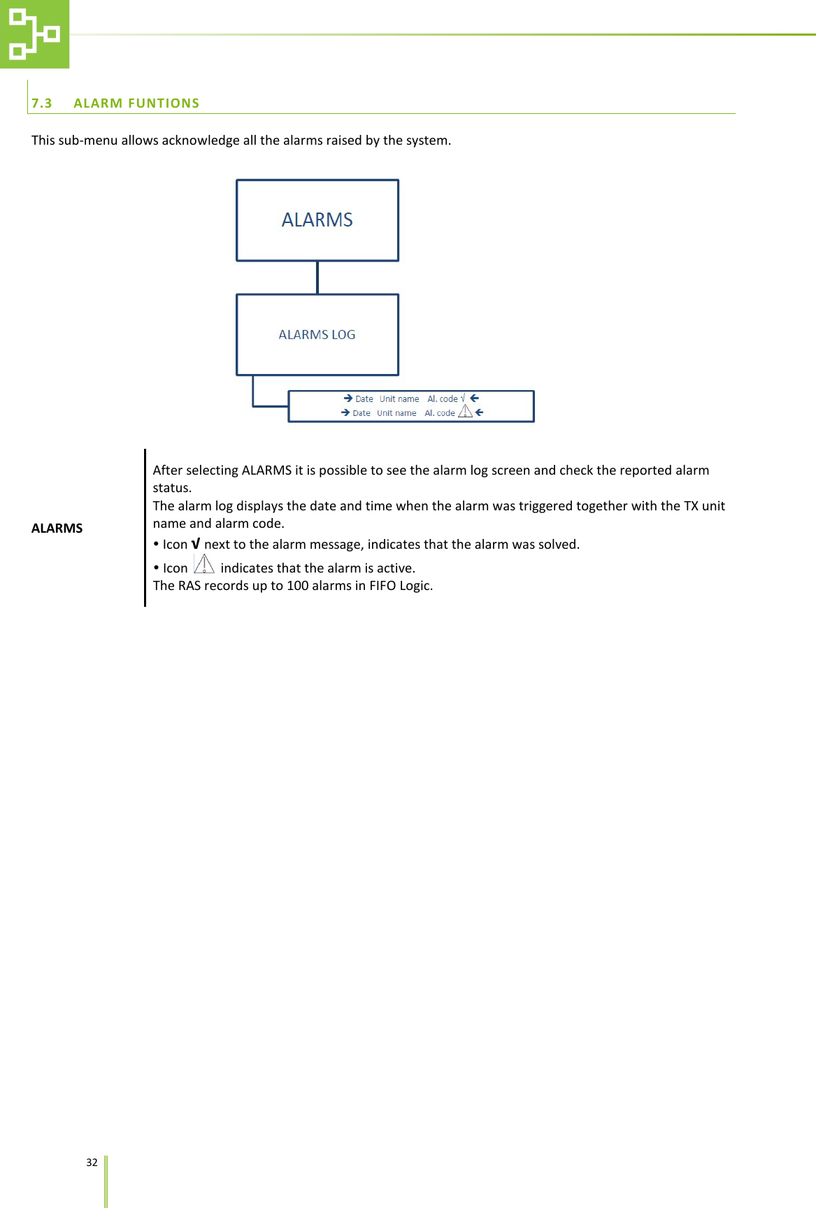
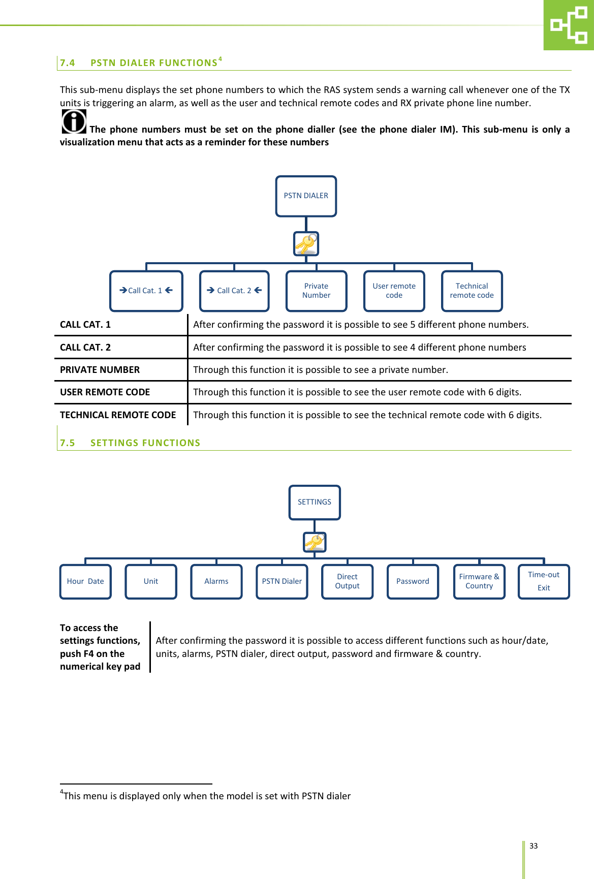
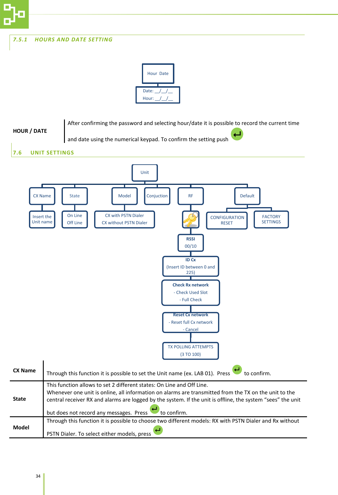
User Manual
Discussion / Help
Navigation