Tecniplast S p A ACBOXRX02 Reception and Remote transmission of Alarm Signals User Manual Remote Alarm System
Tecniplast S.p.A. Reception and Remote transmission of Alarm Signals Remote Alarm System
User Manual
Remote Alarm System
Instructions for Use

Copyright Notice
Copyright © 11/06/2010 TECNIPLAST S.p.A. All rights reserved.
No part of this publication may be reproduced, transmitted, transcribed, stored in a retrieval system, or translated into any language or computer
language without the prior written permission of TECNIPLAST S.p.A.
Trademarks
RAS is a trademark of TECNIPLAST S.p.A.
Technical Support
For technical support, call +39-0332-809711 or send an E- mail to service@tecniplast.it or tecnicom@tecniplast.it

i
I. PREFACE
Dear Customer,
This manual is aimed at providing the user with all the information and safety standards required for the correct and
safe installation, use and maintenance of the equipment you have purchased.
Keep the manual in an easily accessible place, known by the Installer, the operator, the supervisor and the service
technician who should carefully read it to have a clear understanding of the installation, use, and maintenance
procedures as well as hazardous applications to avoid.
This manual is an integral part of the equipment and should follow it, even in the event of a change of ownership, until
final decommissioning.
Should the manual get damaged or lost, a copy can be requested from TECNIPLAST.
In order to receive technical assistance, spare parts or optional extras not required on order, contact TECNIPLAST and
give the equipment serial number, version, and year of manufacture (see label on the equipment).
The Operator, the Supervisor and the Service Technician must know all the standards reported in this manual before
using the equipment or carrying out maintenance procedures.
II. COMPANY CONFORMITY TO ENVIRONMENTAL POLICIES
At TECNIPLAST both our production facilities and our end products reflect our commitment towards environmental
policies in terms of:
• compliance with the principles and contents of current laws and regulations concerning the environment;
• reduction of the environmental impact deriving from our activities, maintaining the right balance between
environmental, social and economic responsibilities;
• on-going quest for innovative applications in order to reduce the environmental impact deriving from waste
materials, energy consumption and to improve the use of natural resources and raw materials.
• preventive evaluation of the environmental impact of new plants and processes and improvement of existing
ones using all possible and economically sustainable solutions to increase our environmental performances.
• incentivation and co-responsibility of employees towards this policy by means of adequate training
• use of effective tools to communicate principles and goals of such an environmental policy to our dealers
during meetings and training courses;
• defining during the design and development of new products the correct use and dismantling instructions to
minimize environmental impact.

2
Table of contents
1 INTRODUCTION .............................................................................................................................................. 4
1.1 MANUFACTURER’S DETAILS ...................................................................................................................................... 4
1.2 TECHNICAL ASSISTANCE ............................................................................................................................................ 4
1.3 UNAUTHORISED MODIFICATIONS ............................................................................................................................. 4
1.4 TECHNICAL SPECIFICATIONS ..................................................................................................................................... 4
1.4.1 TX-WW MODULE ......................................................................................................................................... 4
1.4.2 TX-AMERICA ................................................................................................................................................. 5
1.4.3 CX/RX-WW ................................................................................................................................................... 5
1.4.4 CX/RX-AMERICA ........................................................................................................................................... 5
1.5 OPERATING ENVIRONMENTAL CONDITIONS ............................................................................................................ 6
1.6 COMPLIANCE TO EU DIRECTIVES .............................................................................................................................. 7
1.7 DECLARATION OF CONFORMITY ............................................................................................................................... 7
1.8 RESPONSIBILITY OF THE CUSTOMER ......................................................................................................................... 7
1.9 SPARE PARTS AND TECHNICAL ASSISTANCE ............................................................................................................. 7
1.10 UNAUTHORISED MODIFICATIONS ............................................................................................................................. 8
1.11 WASTE ELECTRIC AND ELECTRONIC EQUIPMENT ..................................................................................................... 8
1.12 DISPOSAL OF OTHER MATERIALS .............................................................................................................................. 8
2 SAFETY PRECAUTIONS .................................................................................................................................... 9
2.1 SAFETY NOTES ........................................................................................................................................................... 9
2.2 GENERAL PRECAUTIONS ........................................................................................................................................... 9
3 APPLICATIONS AND WORKING PRINCIPLE ................................................................................................... 10
3.1 HAZARDOUS AND INAPPROPRIATE APPLICATIONS................................................................................................. 10
3.2 MAIN FEATURES ...................................................................................................................................................... 11
3.2.1 TX TRANSMITTER ....................................................................................................................................... 11
3.2.2 RX AND CX .................................................................................................................................................. 11
4 HANDLING AND TRANSPORTATION ............................................................................................................. 12
4.1 DISPOSAL OF THE PACKAGING ................................................................................................................................ 12
4.2 HANDLING ............................................................................................................................................................... 12
4.3 INCOMING INSPECTION .......................................................................................................................................... 12
4.4 STORAGE ................................................................................................................................................................. 12
5 RAS SYSTEM INSTALLATION GUIDELINES ..................................................................................................... 13
5.1 RX AND CX ELECTRICAL CONNECTIONS................................................................................................................... 13
5.2 HOW TO MOUNT THE RX/CX ON THE WALL ........................................................................................................... 15
5.3 RX, CX AND TX CONNECTION .................................................................................................................................. 16
6 RAS SYSTEM RECEIVER (RX) SOFTWARE USER GUIDE .................................................................................. 18
6.1 MAIN MENU ............................................................................................................................................................ 18
6.2 UNIT MENU ............................................................................................................................................................. 19
6.3 ALARM FUNCTIONS ................................................................................................................................................. 20
6.4 PSTN DIALER FUNCTIONS ........................................................................................................................................ 21
6.5 SETTINGS FUNCTIONS ............................................................................................................................................. 22
6.5.1 HOURS AND DATE SETTING ....................................................................................................................... 22
6.6 UNIT SETTINGS ........................................................................................................................................................ 23
6.6.1 ALARM SETTING PAGE ............................................................................................................................... 24
6.6.2 PSTN DIALER SETTINGS .............................................................................................................................. 25
6.6.3 DIRECT OUTPUT ......................................................................................................................................... 27
6.6.4 PASSWORD SETTING .................................................................................................................................. 28
6.7 FIRMWARE .............................................................................................................................................................. 28
6.8 TIME-OUT EXIT ........................................................................................................................................................ 29
6.9 LANGUAGE SETTING PAGE ...................................................................................................................................... 29
7 RAS SYSTEM CENTRALISED RECEIVER(CX) SOFTWARE USER GUIDE ............................................................ 30
7.1 MAIN MENU ............................................................................................................................................................ 30
7.2 UNIT MENU ............................................................................................................................................................. 31
7.3 ALARM FUNTIONS ................................................................................................................................................... 32
7.4 PSTN DIALER FUNCTIONS ........................................................................................................................................ 33

3
7.5 SETTINGS FUNCTIONS ............................................................................................................................................. 33
7.5.1 HOURS AND DATE SETTING ....................................................................................................................... 34
7.6 UNIT SETTINGS ........................................................................................................................................................ 34
7.6.1 ALARM SETTING PAGE ............................................................................................................................... 35
7.6.2 PSTN DIALER SETTINGS .............................................................................................................................. 36
7.6.3 DIRECT OUTPUT ......................................................................................................................................... 37
7.6.4 PASSWORD SETTING .................................................................................................................................. 38
7.7 FIRMWARE .............................................................................................................................................................. 38
7.8 TIME-OUT EXIT ........................................................................................................................................................ 39
7.9 LANGUAGE SETTING PAGE ...................................................................................................................................... 39
8 ALARMS REPORTED BY THE SYSTEM ............................................................................................................ 40
8.1 ALARMS RAISED BY THE TRANSMITTER (TX) ........................................................................................................... 40
8.2 ALARMS RAISED BY THE RX ..................................................................................................................................... 40

4
1 INTRODUCTION
1.1 MANUFACTURER’S DETAILS
TECNIPLAST S.p.A.
Via I Maggio, 6
21020 BUGUGGIATE (VA)
ITALY
Tel. +39 0332 809 711
Fax +39 0332 458 315
www.tecniplast.it
E-mail : tecnicom@tecniplast.it
service@tecniplast.it
TECNIPLAST S.p.A. reserves the right to modify the specifications to improve the product at any time.
1.2 TECHNICAL ASSISTANCE
Requests for Technical Assistance should be addressed to TECNIPLAST or the authorized Dealer.
1.3 UNAUTHORISED MODIFICATIONS
No modifications to the equipment or its components are to be made without written permission from TECNIPLAST.
Unauthorised modifications could cause changes to the original functioning and consequently:
1. All forms of warranty regarding the entire equipment will be null and void.
2. If the equipment is used in a manner that is not specified by the manufacturer, the protection provided by the
equipment may be impaired.
1.4 TECHNICAL SPECIFICATIONS
1.4.1 TX-WW MODULE
Value
Min
Typ
Max
Power supply
21,6V DC
24V DC
26,4V DC
Power consumption
20mA
Operating frequency EMEA+AU+NZ module
434,4 MHz
Operating frequency for China
431 MHz
Operating frequency for Japan
429,825 MHz
Installation frequency
433,2 MHz
Radiated power for EMEA+AU+NZ+China module
+6dBm
+8dBm
+10dBm
Radiated power for Japan
+3dBm
+6dBm
+7dBm
Radio sensitivity
-113dBm
Dimensions
5,2x11,5 cm
Operating temperature
0 °C
40°C
Protection rating
IP20
5
1.4.2 TX-AMERICA
Value
Min
Typ
Max
Power supply
21,6V DC
24V DC
26,4V DC
Power consumption
20mA
Operating frequency for America
913 MHz
Installation frequency
910 MHz
Radiated power for America
-6dBm
-3dBm
-2dBm
Radio sensitivity
-113dBm
Dimensions
5,2x11,5 cm
Operating temperature
0 °C
40 °C
Protection rating
IP20
1.4.3 CX/RX-WW
Value
Min
Typ
Max
Power supply
110V AC
240V AC
Frequency
50Hz
60Hz
Power supply model (UL:NO)
Morsun LH10 –
10C0512-02 (10W)
Power consumption
0,1A
Relay dry contacts
30Vcc 120Vac 2A
Operating frequency for EMEA+AU+NZ module
434,4 MHz
Operating frequency for China module
431 MHz
Operating frequency for Japan module
429,825 MHz
Installation frequency
433,2 MHz
Radiated power for EMEA+AU+NZ+Cina
+6dBm
+8dBm
+10dBm
Radiated power for Japan
+3dBm
+6dBm
+7dBm
Radio sensivity
-113dBm
Dimensions
23x21,5 cm
Operating temperature
0 °C
40 °C
Protection rating
IP50
1.4.4 CX/RX-AMERICA
Value
Min
Typ
Max
Power supply
110V AC
240V AC
Frequency
50Hz
60Hz
Power supply model (UL:NO)
Morsun LH10 –
10C0512-02 (10W)
Power consumption
0,1A
Relay dry contacts
30Vcc 120Vac 2A
Operating frequency for America module
913 MHz
Installation frequency
910 MHz
Radiated power for America
-6dBm
-3dBm
-2dBm
Radio sensivity
-113dBm
Dimensions
23x21,5 cm
Operating temperature
0 °C
40 °C
Protection rating
IP50

6
IMPORTANT: CHANGES AND MODIFICATIONS NOT APPROVED BY TECNIPLAST COULD VOID THE USER’S AUTHORITY
TO OPERATE THE EQUIPMENT.
This device complies with Part 15 of the FCC Rules. Operation is subject to the following two conditions:
(1) this device may not cause harmful interference, and (2) this device must accept any interference
received, including interference that may cause undesired operation.
This equipment has been tested and found to comply with the limits for a Class A digital device, pursuant to
part 15 of the FCC Rules. These limits are designed to provide reasonable protection against harmful
interference when the equipment is operated in a commercial environment. This equipment generates, uses,
and can radiate radio frequency energy and, if not installed and used in accordance with the instruction
manual, may cause harmful interference to radio communications. Operation of this equipment in a
residential area is likely to cause harmful interference in which case the user will be required to correct the
interference at his own expense.
7
1.5 OPERATING ENVIRONMENTAL CONDITIONS
The equipment has been designed to perform under the following conditions:
• Indoor use
• Altitude up to 2000m
• Temperatures 5°C to 40°C
• Maximum relative humidity 80% for temperatures up to 31°C decreasing linearly to 50% relative humidity at
40°C.
• Mains supply voltage fluctuations up to ± 10% of the nominal voltage
• Transient overvoltages typically present on the mains supply (OVERVOLTAGE CATEGORY II as per IEC 60364-
4-443)
• Pollution degree 2
1.6 COMPLIANCE TO EU DIRECTIVES
DIRECTIVE 1999/05/EC R&TTE
STANDARD EN/60950 - 1:2006 + A11:2009
STANDARD EN/300220 - 2 V2.3.1
STANDARD EN/301489 - 3 V1.4.1
TECNIPLAST S.p.A. reserves the right to modify the specifications to improve the product at any time.
1.7 DECLARATION OF CONFORMITY
The equipment technical documentation includes the DECLARATION OF CONFORMITY in compliance with EU
Equipmentry Directive 1999/05/EC R&TTE.
1.8 RESPONSIBILITY OF THE CUSTOMER
Unless otherwise specified in the contract conditions, the Client shall supply:
▪ Electrical supply complete with EARTH in the vicinity of the equipment.
1.9 SPARE PARTS AND TECHNICAL ASSISTANCE
In order to conform to the terms and duration of the Warranty and to ensure perfect inter-changeability, only original
TECNIPLAST spare parts are to be used.
Requests for Technical Assistance should be addressed to TECNIPLAST or the authorized Dealer.

8
1.10 UNAUTHORISED MODIFICATIONS
No modifications to the equipment or its components are to be made without written permission from TECNIPLAST.
Unauthorised modifications could cause changes to the original functioning and consequently:
1. All forms of warranty regarding the entire equipment will be null and void.
2. If the equipment is used in a manner that is not specified by the manufacturer, the protection provided by
the equipment may be impaired
1.11 WASTE ELECTRIC AND ELECTRONIC EQUIPMENT
Tecniplast is committed to meeting the requirements of the EU directive 2002/96/EC amended by 2003/108/EC on
Waste Electric and Electronic Equipment (WEEE) and, therefore, promotes “the reuse, recycling and other forms of
recovery of such wastes (WEEE) so as to reduce the disposal of waste. It also seeks to improve the environmental
performance of all operators involved in the life cycle of electrical and electronic equipment, e.g. producers,
distributors and consumers...”
Tecniplast has worked closely with its suppliers to eliminate hazardous materials from its products. There are
instances, however, where it has not yet been possible to completely eliminate all such materials. Consequently, some
products are labelled with a crossed-out "wheelie" symbol, indicating that special care must be applied to their
disposal and / or recycling.
DO NOT dispose of WASTE ELECTRIC AND ELECTRONIC EQUIPMENT as unsorted municipal waste.
Waste electric and electronic equipment is to be collected and disposed of separately in specialised treatment
facilities in compliance with EU legislation and any laws and regulations in force in the country where the machinery is
installed.
1.12 DISPOSAL OF OTHER MATERIALS
DO NOT dispose of plastic material as unsorted municipal waste. Any plastic material is to be collected and disposed
of separately in compliance to any norm and regulation in force in the country where the machinery is installed.
DO NOT dispose of metallic material as unsorted municipal waste. Any metallic material is to be collected and
disposed of separately in compliance to any norm and regulation in force in the country where the machinery is
installed.
Contact Tecniplast to have detailed specifications and procedures on how to disassemble the EQUIPMENT.
9
2 SAFETY PRECAUTIONS
2.1 SAFETY NOTES
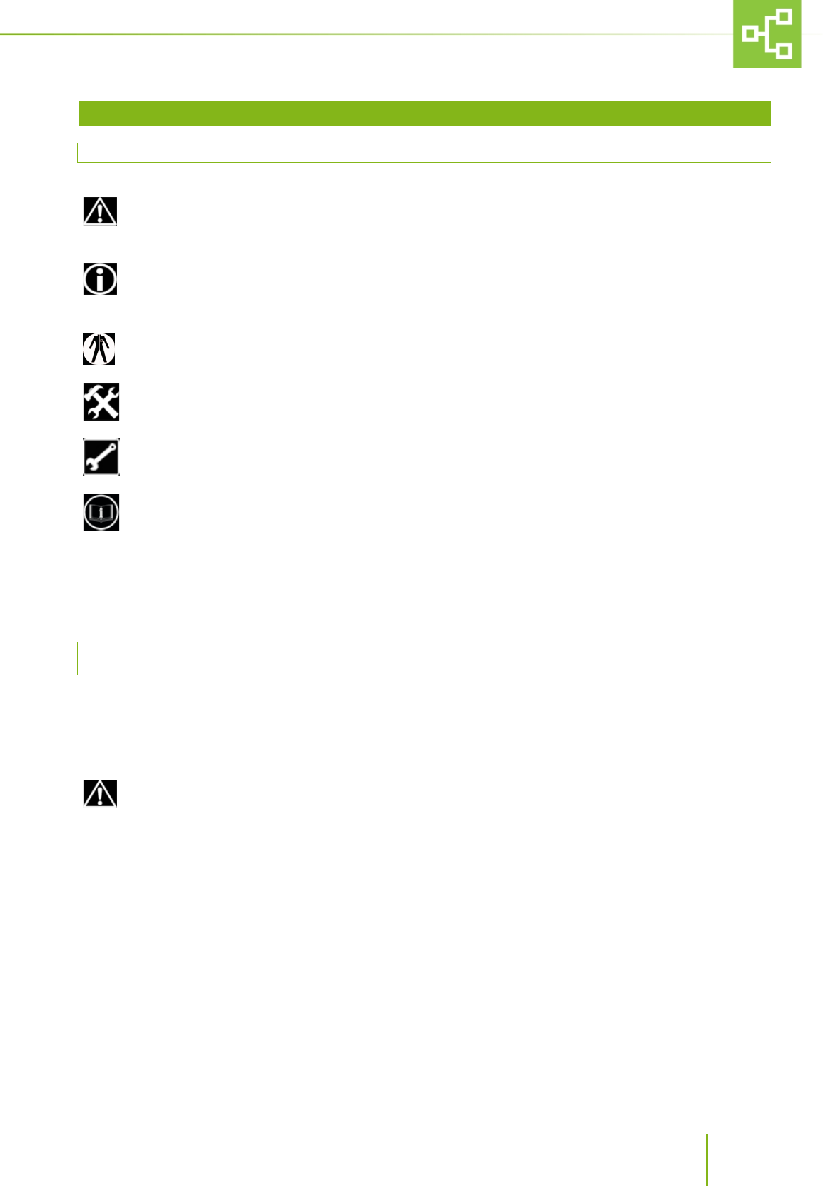
The following words and symbols are used in order to explain safety procedures.
- This symbol is used in safety messages and on labels when there is an imminently hazardous situation which,
if not avoided, may result in death, serious injury or serious damage to the equipment.
These safety messages also describe how the hazard can be avoided.
- This symbol is used to explain any procedures which, if performed incorrectly, could cause damage or
potential problems to the equipment.
- This symbol is used to indicate the need to wear personal protective equipment to carry out a specific procedure.
- This symbol is used to indicate that a certain procedure is to be carried out by trained service personnel only.
- This symbol is used to indicate the need to use specific tools and equipment.
- This symbol is used in safety messages and on labels whenever there is the need to refer to product instructions for use.
NOTE - Annotations are made for information which requires specific consideration about any procedures, but for
which there is no risk of damaging the equipment.
Pay special attention to all Safety Warnings given throughout the instructions
For any doubts regarding safety, contact TECNIPLAST.
2.2 GENERAL PRECAUTIONS
The equipment is to be used by authorised and qualified personnel only.
Follow all the precautions, procedures and safety measures prescribed by the standards in force to safeguard personal
health and safety.
Before using the equipment the user must have a clear understanding of the positioning and functions of the
commands.
▪ Do not carry out modifications that might alter the performance or the working conditions of the equipment;
TECNIPLAST disclaims all responsibility for personal injury or material damage caused by mishandling of the
equipment.
▪ If the equipment is used in a manner that is not specified by the manufacturer, the protection provided by the
equipment may be impaired.
▪ Do not use the equipment in an explosive environment.
▪ Read the user manual before use.
▪ Ensure the equipment is stable and balanced before starting operating.
▪ DO NOT leave the equipment unattended while working.
10
3 APPLICATIONS AND WORKING PRINCIPLE
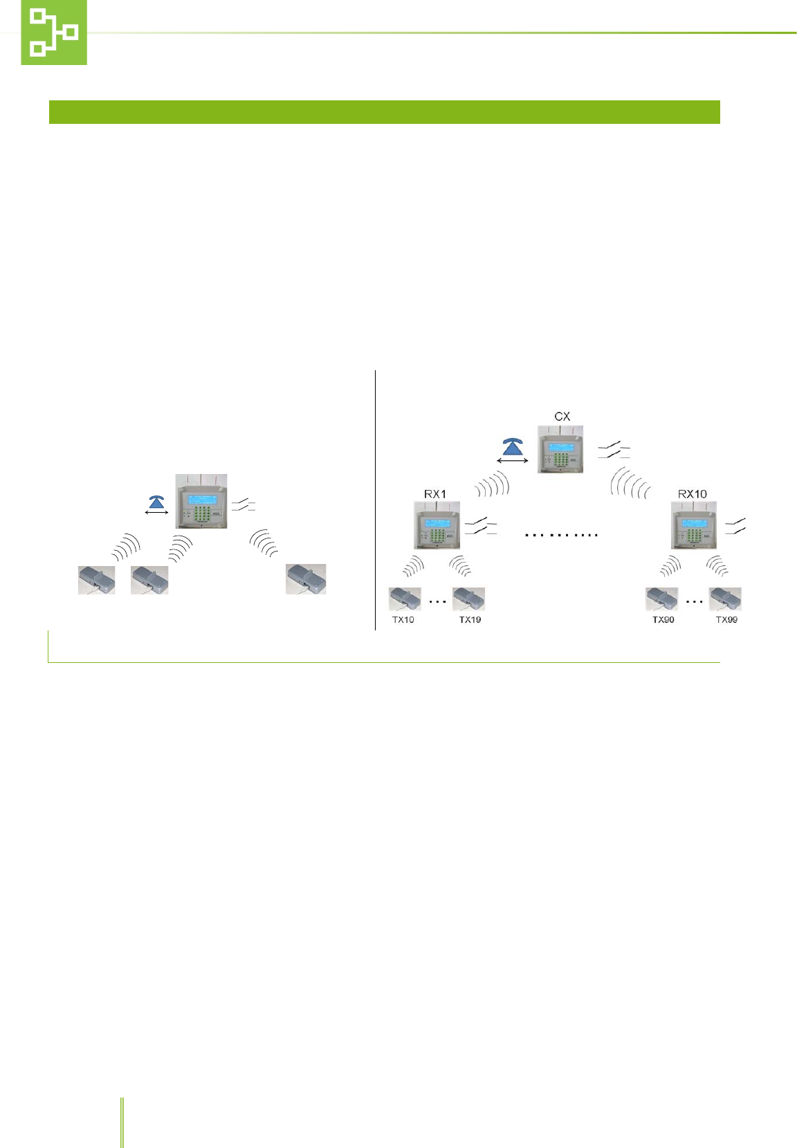
Tecniplast Remote Alarm System (RAS) has been developed to simplify the work of facility managers and operators by
providing them with an easy-to-use monitoring of Tecniplast equipment and machines.
Each piece of equipment features a transmitter (the TX) which transmits any alarm condition to a receiver (the RX).
Each receiver (ideally located inside one of the facility rooms), is designed to receive signals from 10 transmitters and
to send at the same time an alarm message to a centralised receiver (the CX) which can monitor a number of RX
simultaneously (maximum 10).
Any time an alarm is transmitted to the RX (and CX), the system sends a voice message to the phone numbers
recorded in the RX setting pages by means of a PSTN dialer*.
Voice messages may be customised by the user following the dialer instructions for use directly on the phone.
Up to 100 Alarm messages are logged by the system in FIFO logic.
Simple System
TX1 TX2 TX10
................
RX+ PD
Complex System
3.1 HAZARDOUS AND INAPPROPRIATE APPLICATIONS
Tecniplast disclaims all responsibility for any uses other than those stated in this User Manual unless previously
authorised.
Here is a list of some hazardous applications that should be avoided:
• Operation by inexperienced or untrained personnel.
• Housing in an environment not compliant to the “Environmental Requirements” described in TABLE 1 - TECHNICAL
SPECIFICATIONS
• Operation of the equipment with highly flammable materials.
• Operation of the equipment in an explosive environment.
TECNIPLAST disclaims all responsibilities deriving from improper use and incorrect maintenance
If the equipment is used in a manner that is not specified by the manufacturer, the protection provided by the
equipment may be impaired
* The PSTN dialer is installed in the WW version only. All the related function will not be available on the
AMERICA version unit.
11
3.2 MAIN FEATURES
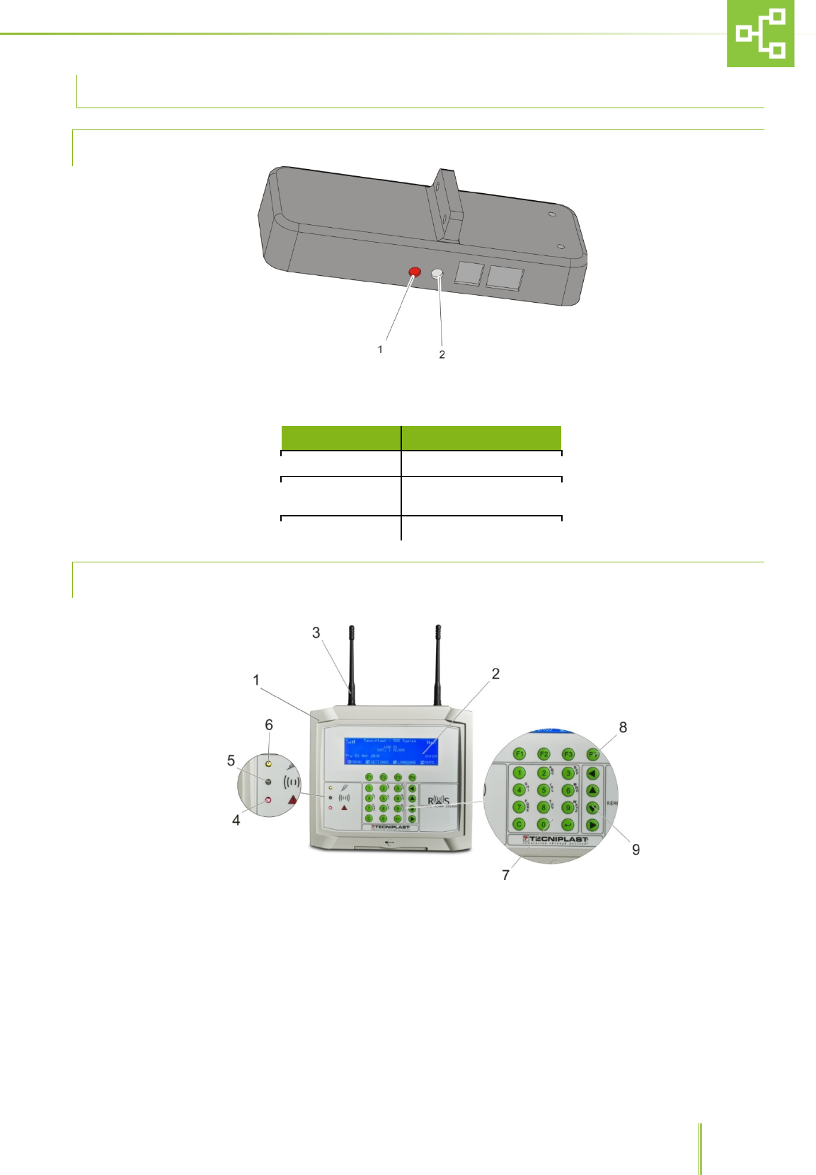
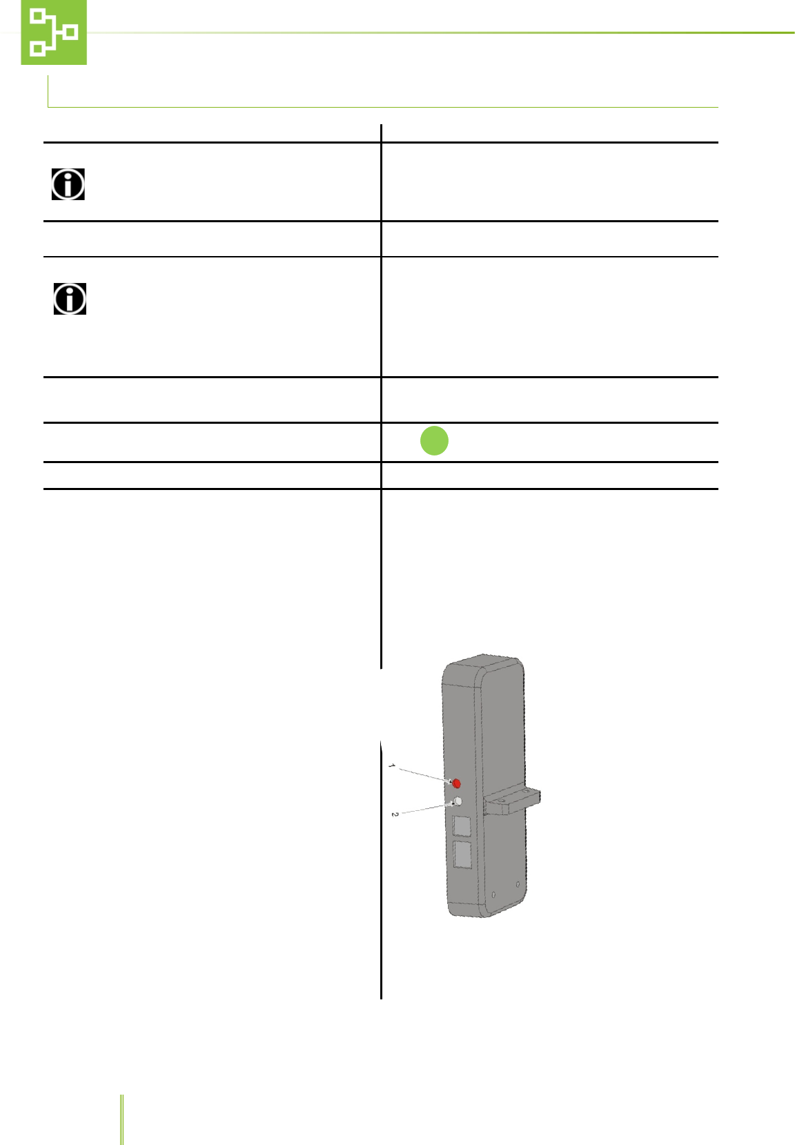
3.2.1 TX TRANSMITTER
1. LED
2. TX Connection Key
TX LED STATUS (on-line, off-line)
TX STATUS
LED
Not linked
blink
Linked , on-line
Off (On during transmission
every 30 – 45 seconds)
Linked , off-line
On
3.2.2 RX AND CX
1. RAS system control panel
2. Screen
3. Antenna
4. Red LED
5. Green LED
6. Yellow LED
7. Alpha-numerical keypad
8. F1, F4 control keys
9. Scroll arrows.

12
4 HANDLING AND TRANSPORTATION
4.1 DISPOSAL OF THE PACKAGING
Dispose of the packaging in compliance with laws and regulations in force in the country where the
equipment is installed.
Collect the packaging and disposed of it separately in compliance with any law and regulation in force in the country
where the equipment is installed.
DO NOT dispose of plastic film wrapping as unsorted municipal waste.
Any plastic material is to be collected and disposed of separately in compliance to laws and regulations in force in the
country where the equipment is installed.
4.2 HANDLING
The handling of the equipment and of its separate accessories must be carried out by trained personnel.
It is advisable to transport the RAS directly to the site where it is going to be installed before removing the
packaging.
4.3 INCOMING INSPECTION
Upon delivery, unpack the equipment and inspect it for damage. If the equipment has been mishandled, dented or
damaged, alert the carrier and Technical Assistance immediately.
4.4 STORAGE
The RAS is designed for indoor use only.
Always keep the equipment in a dry place, whether packaged or not.
If the equipment is not deemed to be used, cover it with a piece of cloth or plastic to protect it from dust and store it
in an environment compliant with the environment requirements specified in paragraph 1.5 “OPERATING
ENVIRONMENTAL CONDITIONS” on page 6.
If the equipment has been moved, packed and stored, after a period of use (e.g. if there is a change of laboratory or
plant), contact Tecniplast technical assistance or the distributor in order to have accurate and precise instructions on
how to put it back into service
13
5 RAS SYSTEM INSTALLATION GUIDELINES
5.1 RX AND CX ELECTRICAL CONNECTIONS
The RAS is to be connected to the power supply protected by suitable protections in compliance with laws
and regulations in force in the country where the machine is installed.
The RAS is to be installed in compliance with IEC/EN 60950 Standard, and controlled by an external cut off switch.
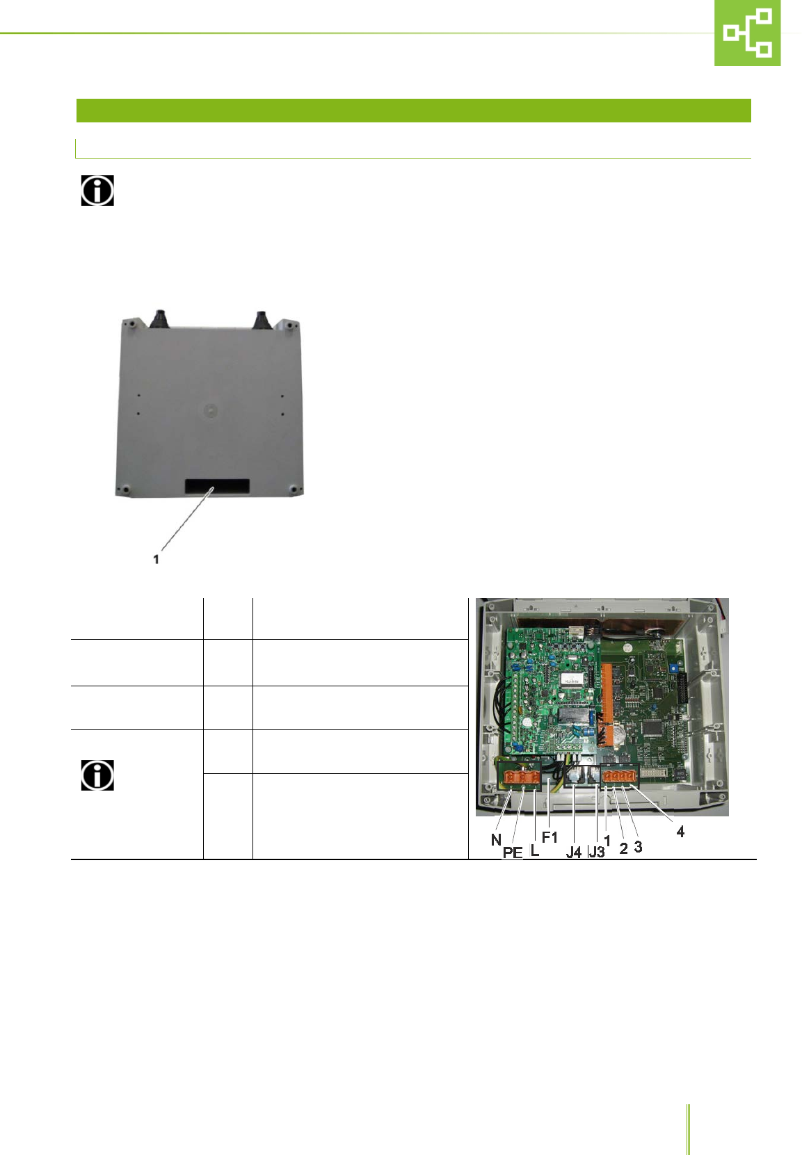
Before installing the system, connect the Rx and CX to the power supply cable, phone cable and outputs as shown
hereunder:
• Insert the cables into the slot on the RX and CX housing.
• Carry on with the following electrical connections:
M5
L
PE
N
POWER SUPPLY CABLE CONNECTION
POINT
F1 FUSE
5X20mm – 1,6 A (TIME LAG) LOW
BREAKING CAPACITY 250 Vac. –
T1.6AL 250V
J4
J3 LINE
PHONE TELEPHONE CABLE Rj11 – 4 poles
M3 CONNECTOR
CONNECT ONLY
SELV (SAFETY EXTRA
LOW VOLTAGE)
OPERATING CIRCUITS
1
2 DIRECT OUTPUT 1
3
4 DIRECT OUTPUT 2
14
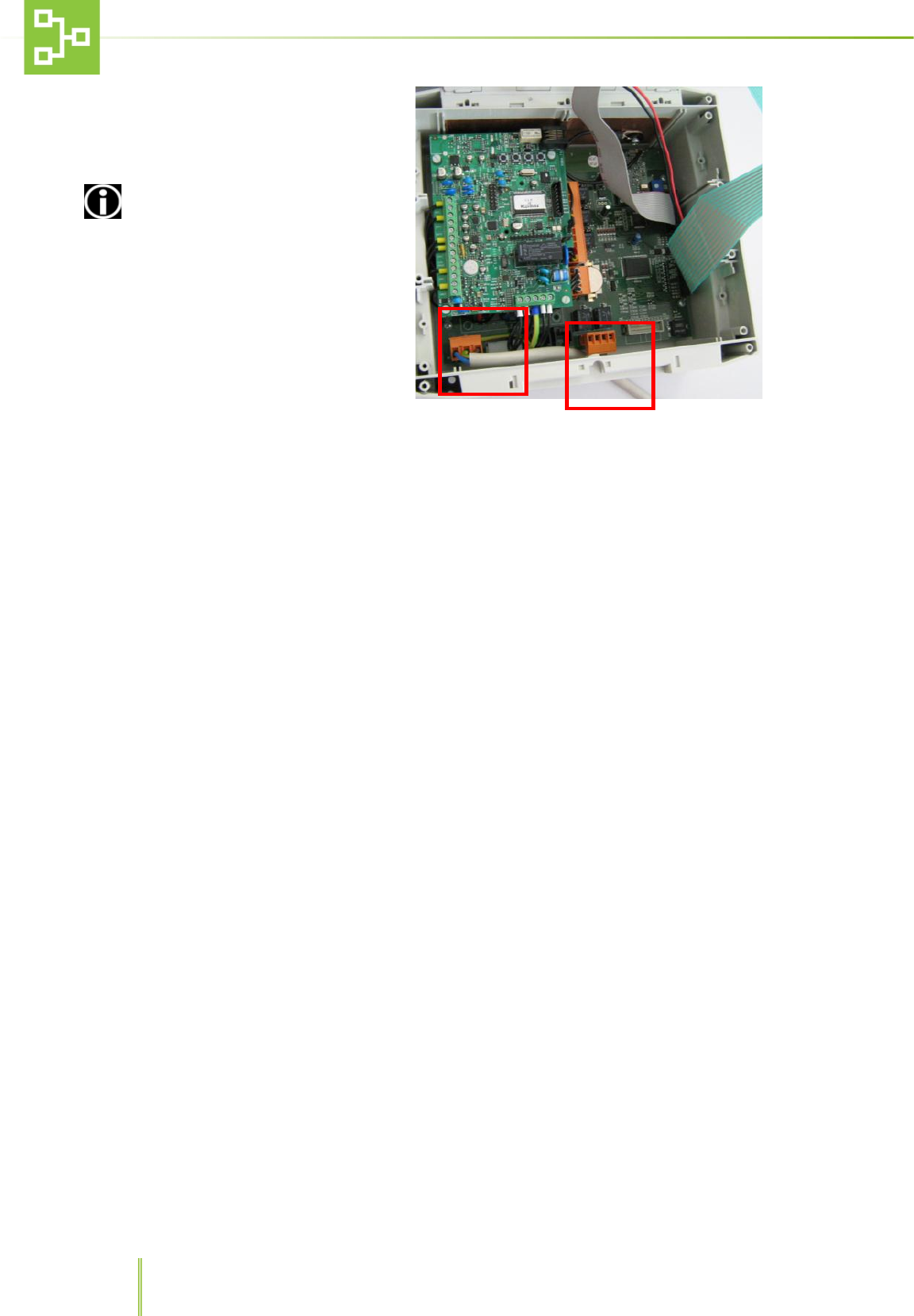
•
Insert the connectors into their
housing (M5 - power supply, M3 –
alarm contact, if required by
installation specs) and, if necessary,
fix them into position.
Connect the power supply
cable and signal cables so as to
guarantee adequate clearance
between mains and SELV circuits so
that they do not get in contact.
15
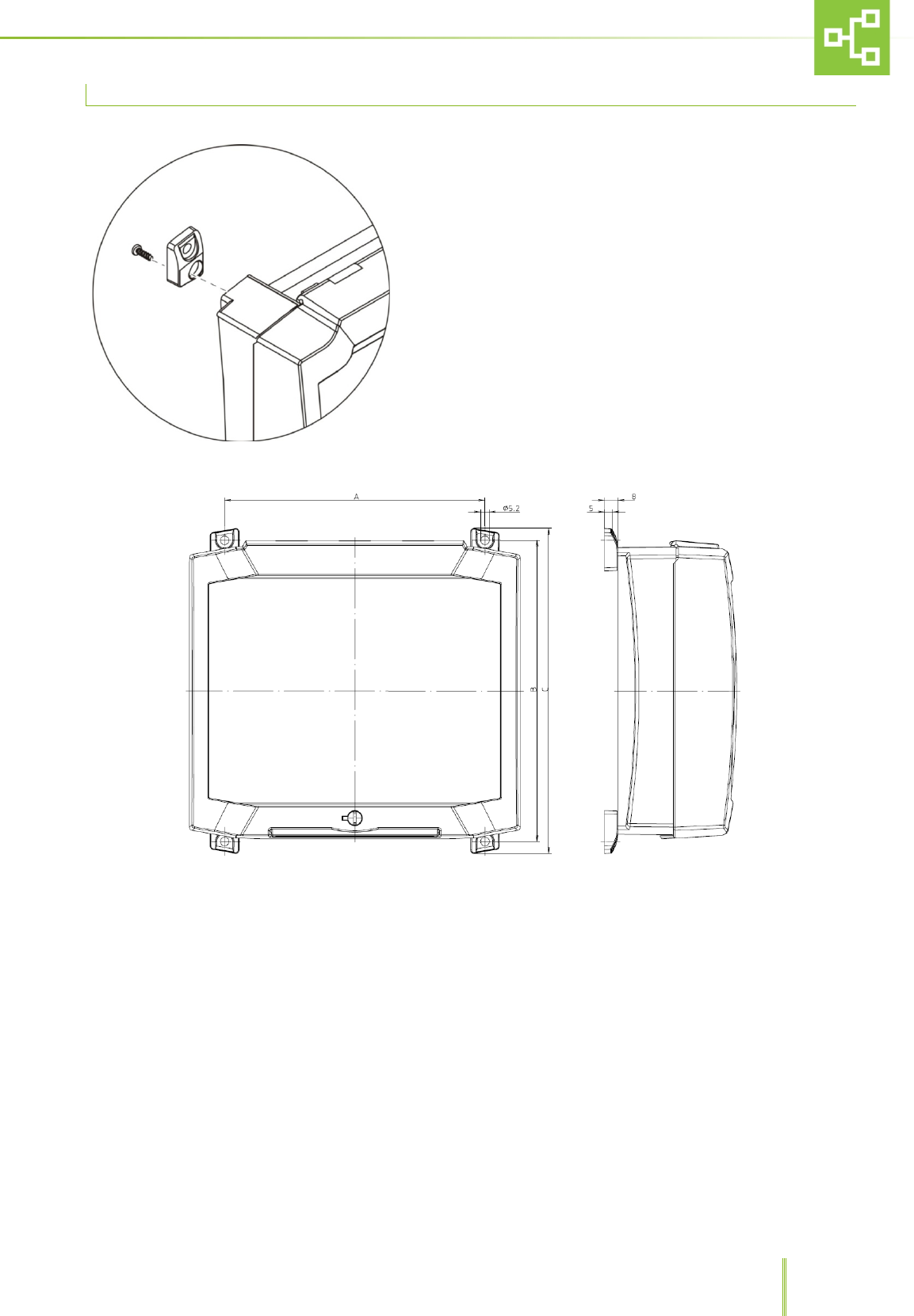
5.2 HOW TO MOUNT THE RX/CX ON THE WALL
• Screw the support plates to the RX – CX housing
• Mark four holes on the wall at the most convenient height
• Drill the wall and insert the screw anchors.
• Screw the RX – CX housing to the wall.
16
5.3 RX, CX AND TX CONNECTION
1. Turn on the CX (if present)
2. Set an ID for each CX
If there are many CX installed in the same site,
each CX must be given a different ID.
SETTINGSUNITRFID CX.
3. Set an ID for each RX SETTINGSUNITRFID RX
4. Set the Country where the system is installed
Ensure the selected Country Setting is the same
on both the CX and RX before connecting them. Such
setting is enabled only during the first start-up or after
resetting the sub-network or before connecting the RX.
SETTINGSUNITRFCOUNTRY
5. Connect the RX to the CX (if present)
•
RX: SETTINGSUNITCONJUNCTION
• CX: MENUUNITRECORD
6. The RX screen displays the detected CX.
Push to connect the RX to the CX
7.
Enter the RX Name on CX
8. Connect the TX to RX
• Check the TX is connected.
Record the TX on the RX
• RX: MENUUNITRECORDRECORD THE
UNIT
• Press the connection key on the TX (picture
below, n. 2) (led 1 off means connected)
•
Enter the TX name on RX.

17
9. Switch off a Unit already registered into the
system without generating any Alarm (e.g. for
disinfection activity on the Unit)
• Before switching off the Unit, press the
connection Key for 2 sec and the LED will be ON.
• On the RX the Unit will be considered OFFLINE
and any alarm triggered by the AHU will not be
sent to the RX.
• Press the connection Key again for 2 sec and the
Unit will be ON-LINE again.
10.
Reset the TX
(If any problem arises)
• Turn off the AHU.
• Keep pressed the connection key (2) and turn on
the AHU again.
• Keep pressed for at least 10 seconds.
•
System should be set again from the beginning.
Follow the same procedure to connect all the RX, CX and TX .
18
6 RAS SYSTEM RECEIVER (RX) SOFTWARE USER GUIDE
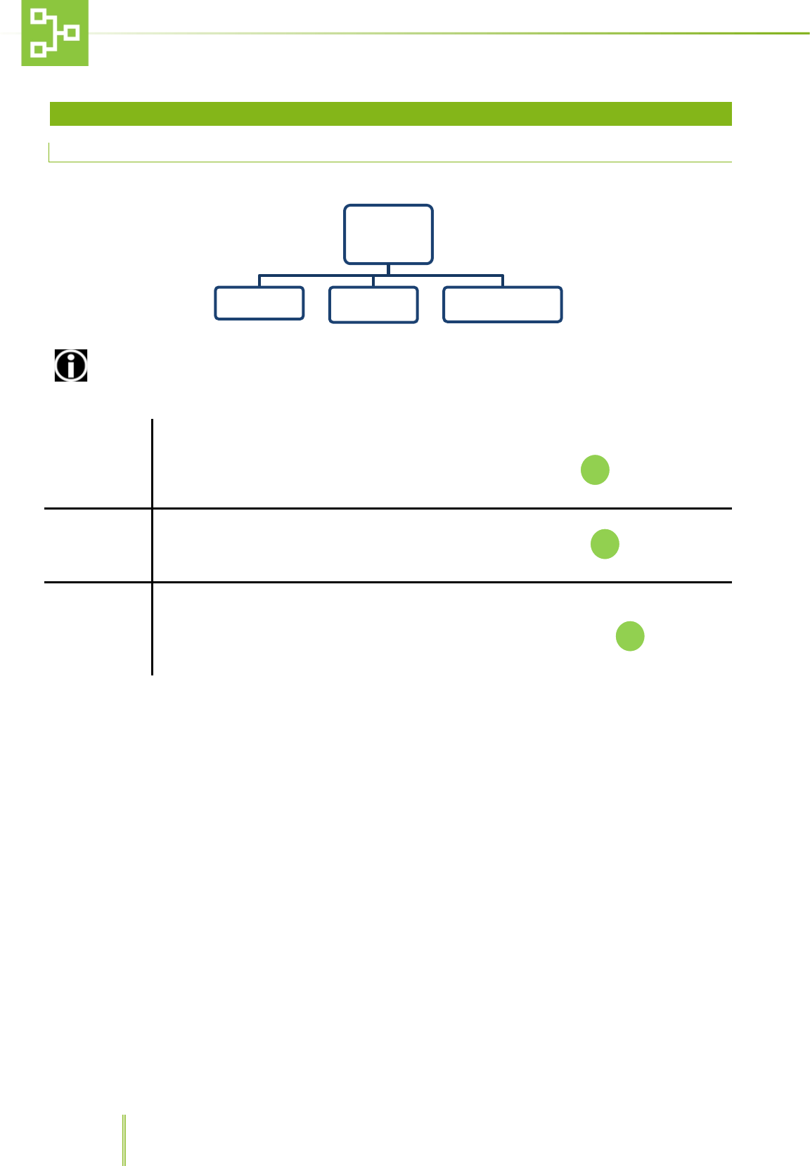
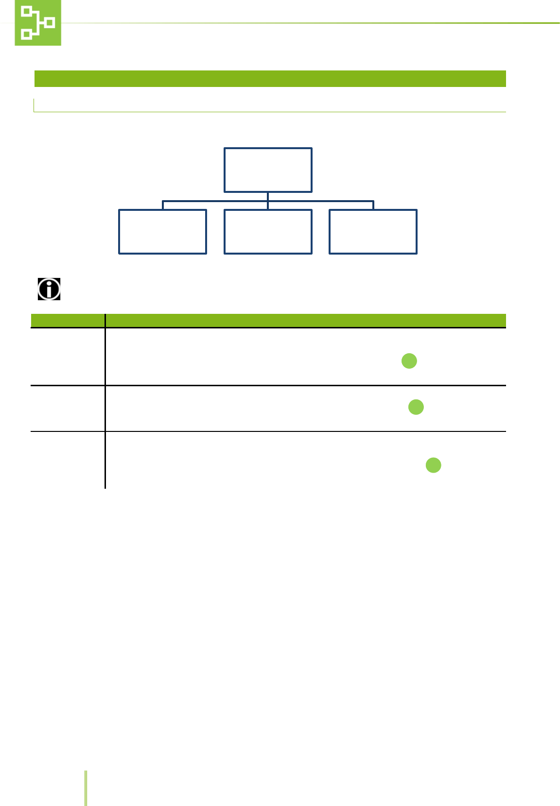
6.1 MAIN MENU
To open the main menu, press key F1.
ACCESS TO SOME FUNCTIONS IS ALLOWED TO SUPERVISORS ONLY.
UNIT
This function allows the user to view, record, delete and rename the units connected to the
system.
Select UNITS from the MENU list using the UP/DOWN arrows, then push to enter the sub-
menu.
ALARMS
This function allows to view the alarm log.
Select ALARMS from the MENU list using the UP/DOWN arrows, then push to enter the sub-
menu.
PSTN DIALER*
This function allows the user to display the phone numbers to which the system has to send the
notifications according to the different alarm priority.
Select PSTN DIALER from the MENU list using the UP/DOWN arrows, then push to enter the
sub-menu.
MENU
UNIT ALARMS PSTN DIALER
19
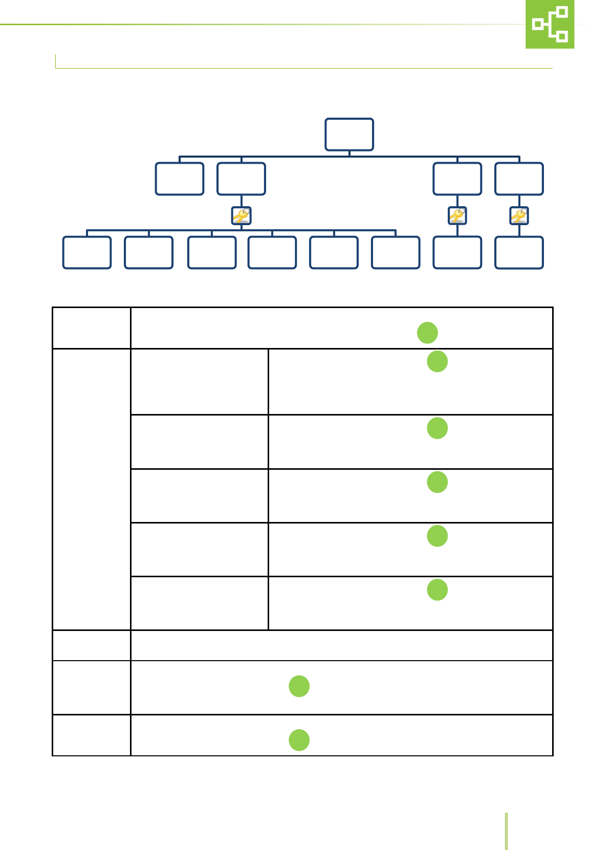
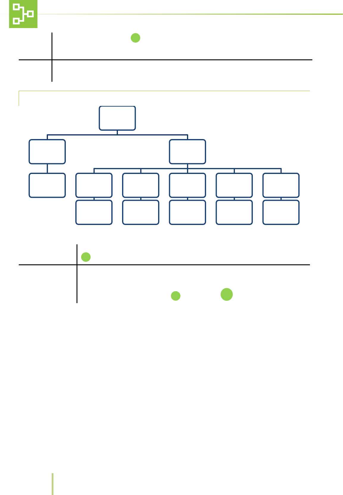
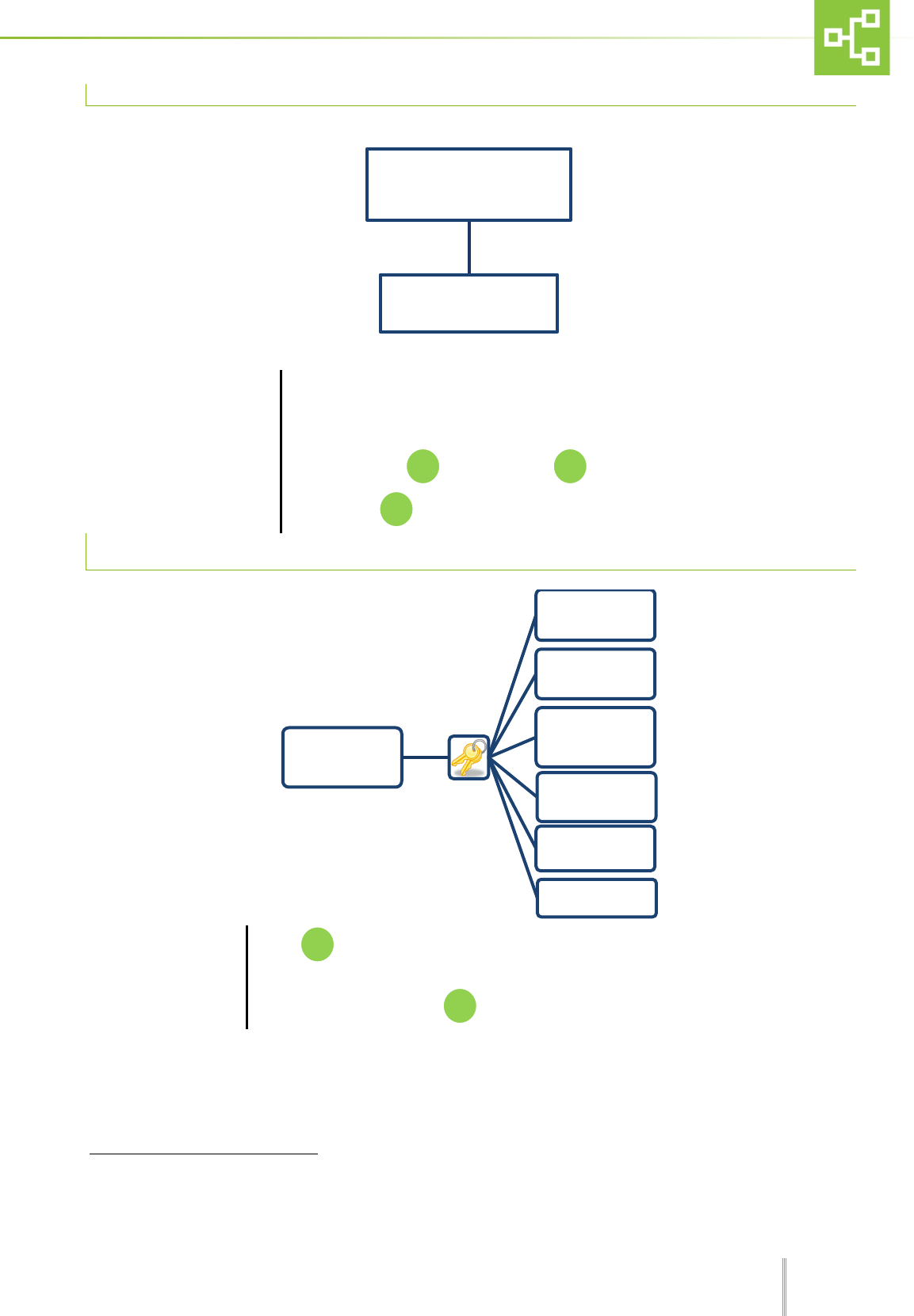
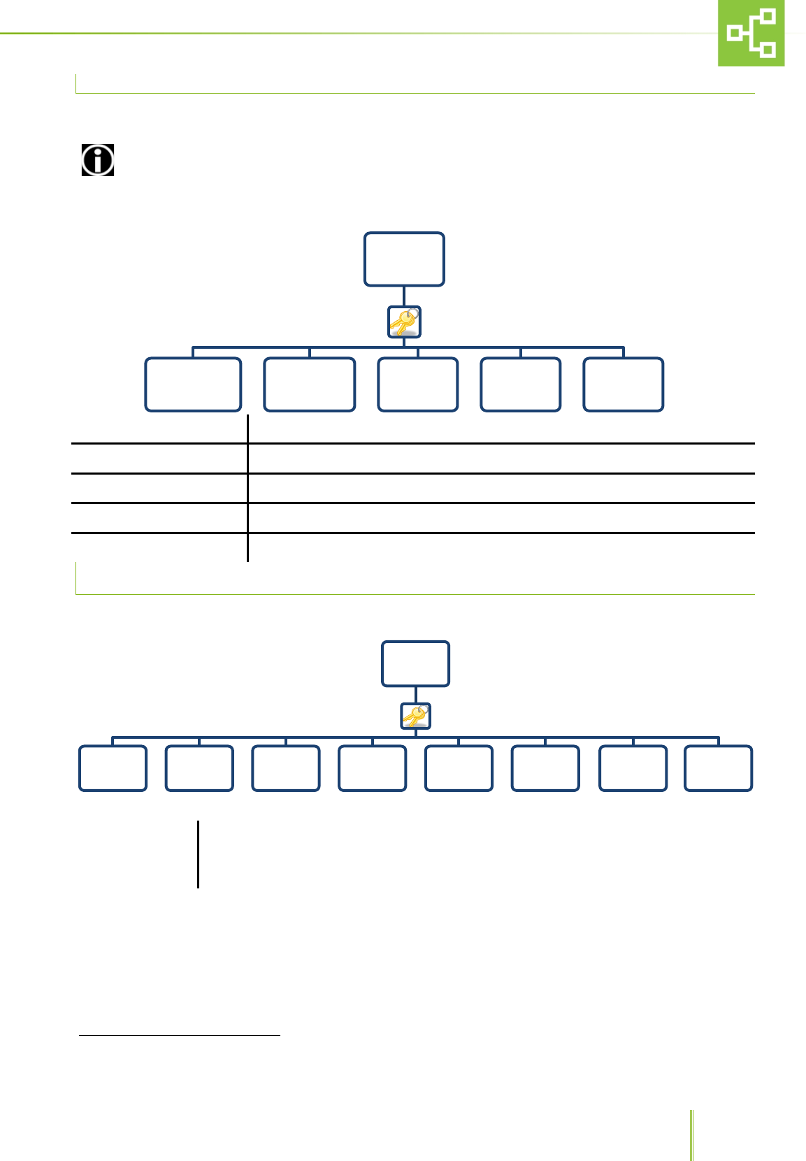
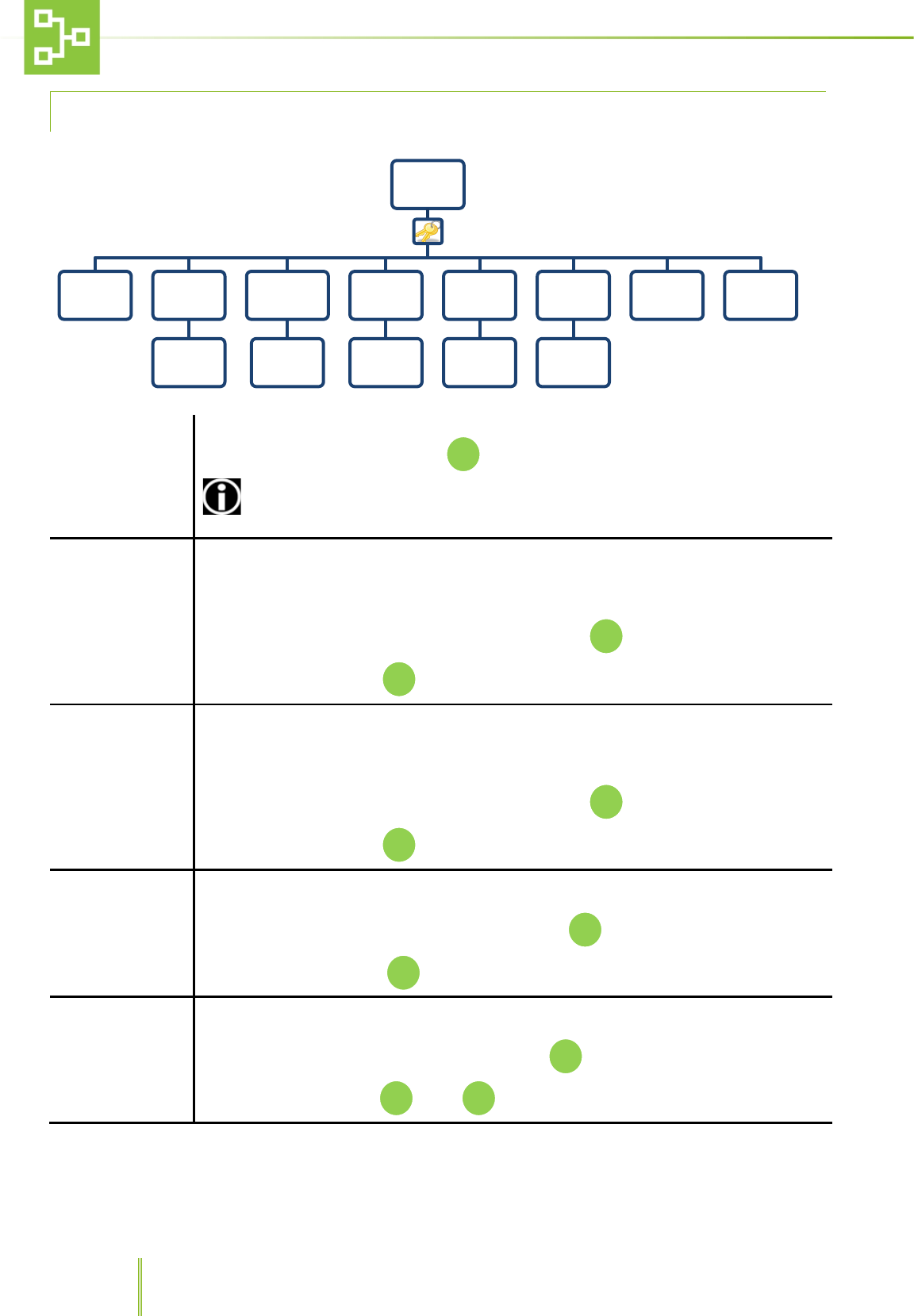
6.2 UNIT MENU
VIEW
This function allows to check the connected TX state.
To check the connected transmitters (TX) connection status push
RECORD
Record the unit (standard)
After confirming the password push .
The system will ask to press the pushbutton on the unit
transmitter (Tx ) to record the TX to the RAS system. In this
configuration it is not possible to send any alarm.
Record the unit (IVC) After confirming the password push .
The system will ask to press the pushbutton on the IVC unit
transmitter (Tx ) to record the TX to the RAS system.
Record the unit (MVC) After confirming the password push .
The system will ask to press the pushbutton on the Ventilated
Cabinet unit transmitter (Tx ) to record the TX to the RAS system.
Record the unit (ISO) After confirming the password push .
The system will ask to press the pushbutton on the ISOCAGE unit
transmitter (Tx ) to record the TX to the RAS system.
Record the unit (DCC) After confirming the password push .
The system will ask to press the pushbutton on the DCC unit
transmitter (Tx ) to record the TX to the RAS system.
CANCEL Returns to the Menu
ERASE
This function allows to delete the TX from the RX.
After confirming the password push and delete the TX which you do not want to be
recorded any longer.
RENAME
This function allows to rename the TX ID.
After confirming the password push and rename the TX
UNIT
VIEW RECORD
RECORD THE
UNIT
( STANDARD)
RECORD
THE UNIT
(IVC)
RECORD THE
UNIT
(MVC)
RECORD THE
UNIT
(ISO)
RECORD
THE UNIT
(DCC)
CANCEL
ERASE
Unit
name
RENAME
Unit
name
20
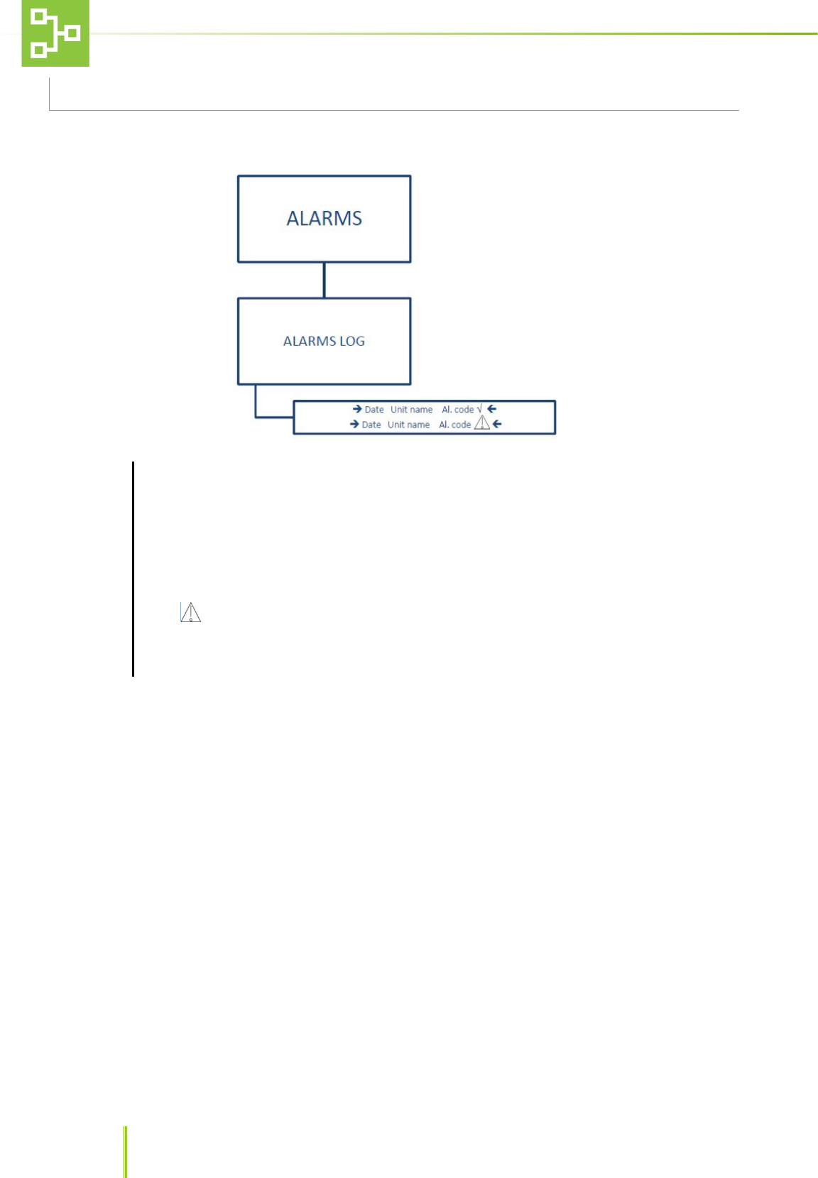
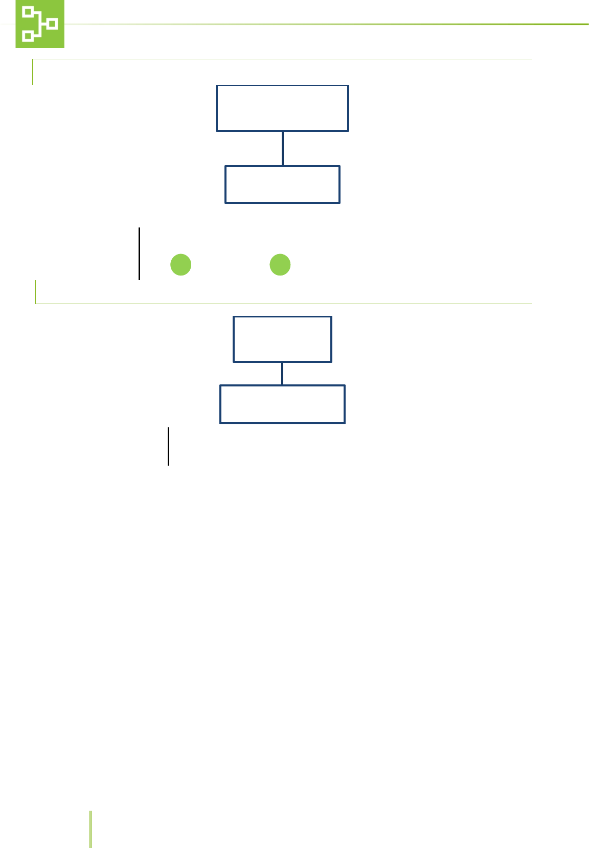
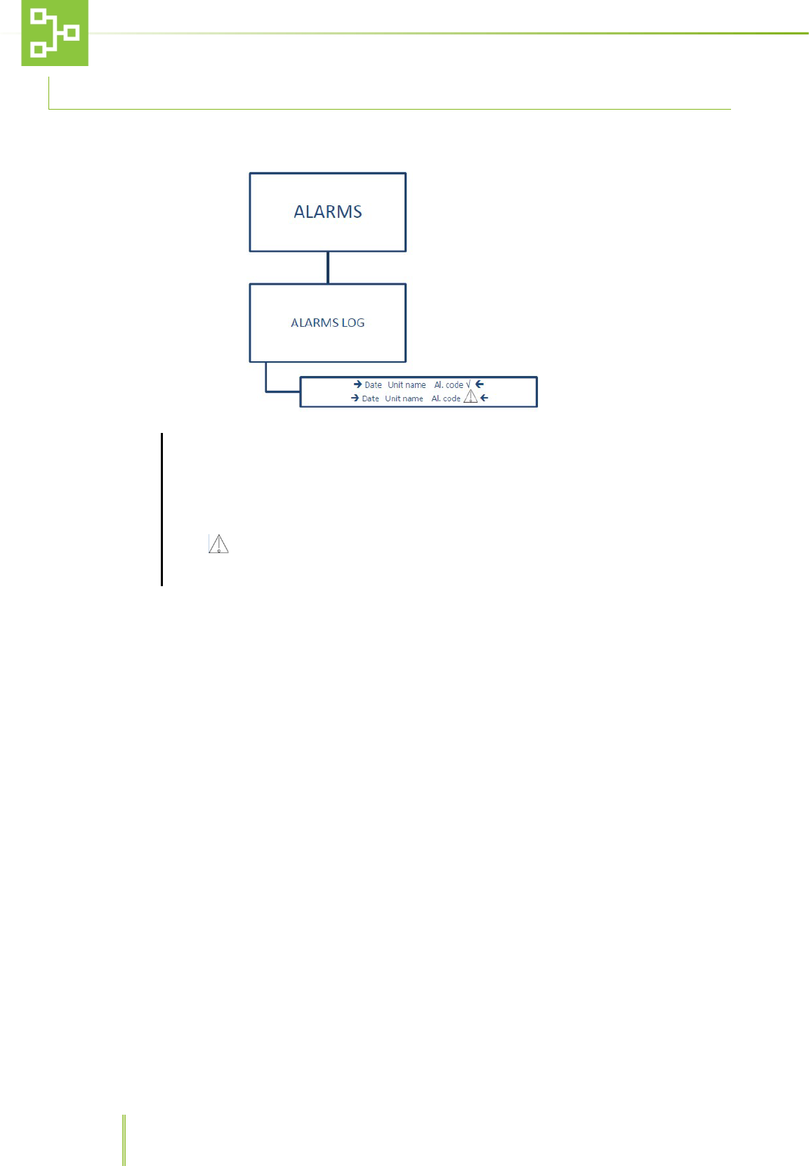
6.3 ALARM FUNCTIONS
This sub-menu allows to view all the alarms raised by the system.
ALARMS
After selecting ALARMS it is possible to see the alarm log screen and check the reported alarm status.
The alarm log displays the date and time when the alarm was triggered together with the TX unit
name and alarm code.
Icon √ next to the alarm message, indicates that the alarm was solved.
Icon indicates that the alarm is active.
The RAS records up to 100 alarms in FIFO Logic.
21
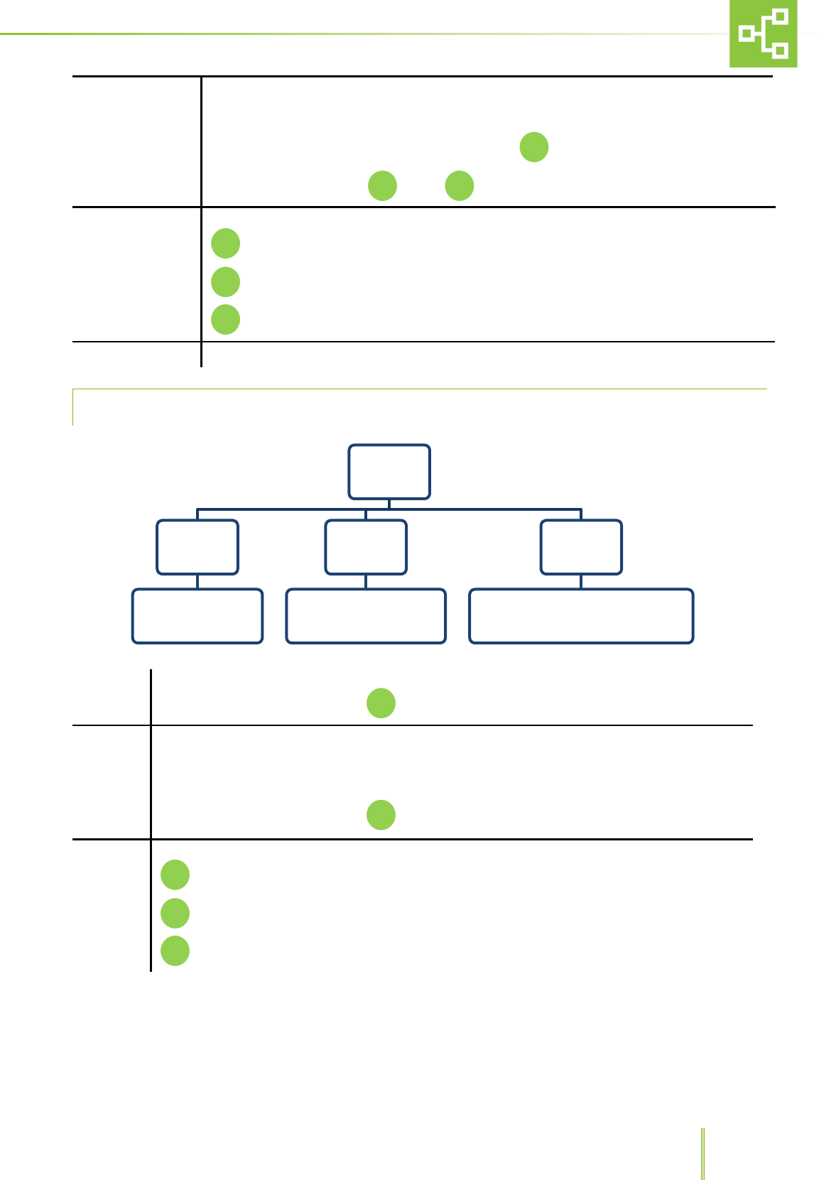
6.4 PSTN DIALER FUNCTIONS1
This sub-menu displays the set phone numbers to which the RAS system sends a warning call whenever one of the TX
units is triggering an alarm, as well as the user and technical remote codes and RX private phone line number.
The phone numbers must be set on the phone dialler (see the phone dialer IM). This sub-menu is only a
visualization that act as a reminder for these numbers
CALL CAT. 1 After confirming the password it is possible to see 5 different phone numbers.
CALL CAT. 2 After confirming the password it is possible to see 4 different phone numbers
PRIVATE NUMBER Through this function it is possible to see a private number.
USER REMOTE CODE Through this function it is possible to see the user remote code with 6 digits.
TECHNICAL REMOTE CODE Through this function it is possible to see the technical remote code with 6 digits.
1 This menu is enabled only if the set model with PSTN dialer
PSTN
DIALER
Call Cat.
1
Call
Cat. 2
Private
Number
User
remote
code
Technical
remote
code
22
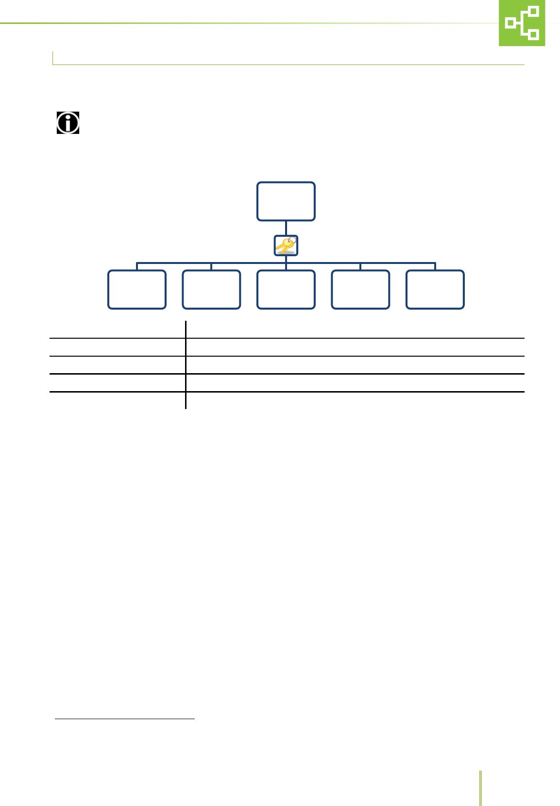
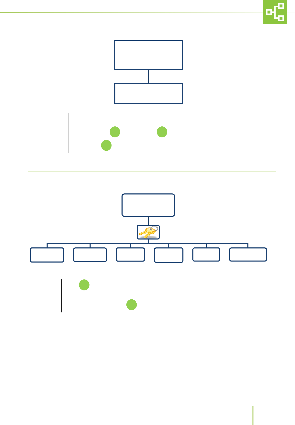
6.5 SETTINGS FUNCTIONS
To access the
settings functions,
push F2 on the
numerical key pad
After confirming the password it is possible to access different functions such as hour/date,
units, alarms, PSTN dialer, direct output, password and firmware & country.
6.5.1 HOURS AND DATE SETTING
HOUR / DATE
After confirming the password and selecting hour/date it is possible to record the current time
and date using the numerical keypad. To confirm the setting push
SETTINGS
Hour Date Unit Alarms PSTN Dialer Direct
Output Password Firmware &
Country
Time-out
Exit
Hour Date
Date: __/__/__
Hour: __/__/__
23
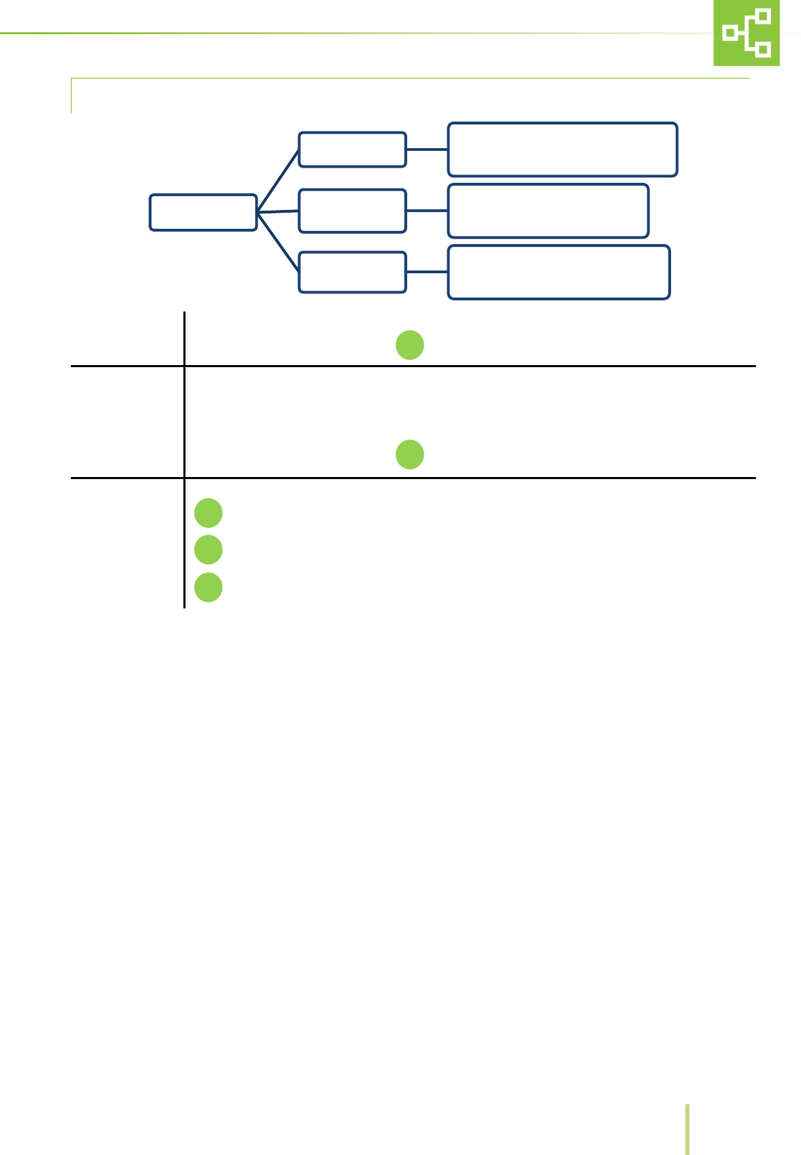
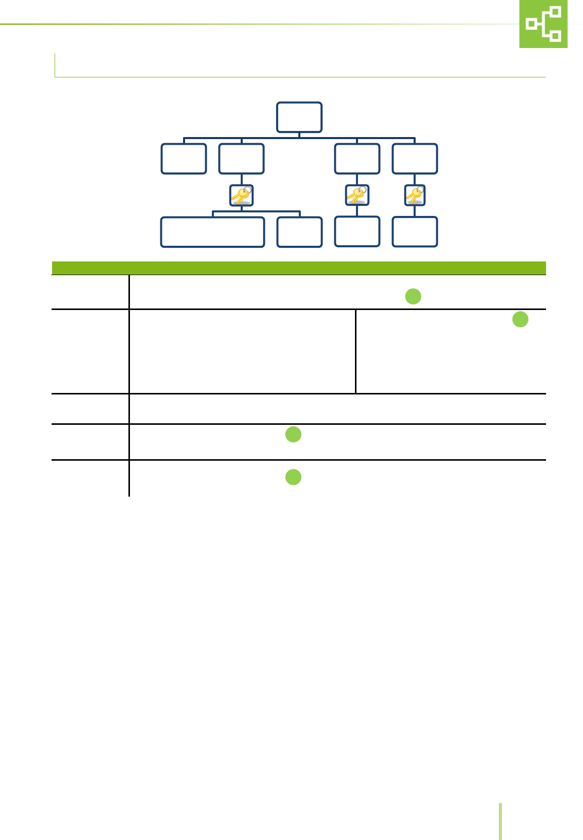
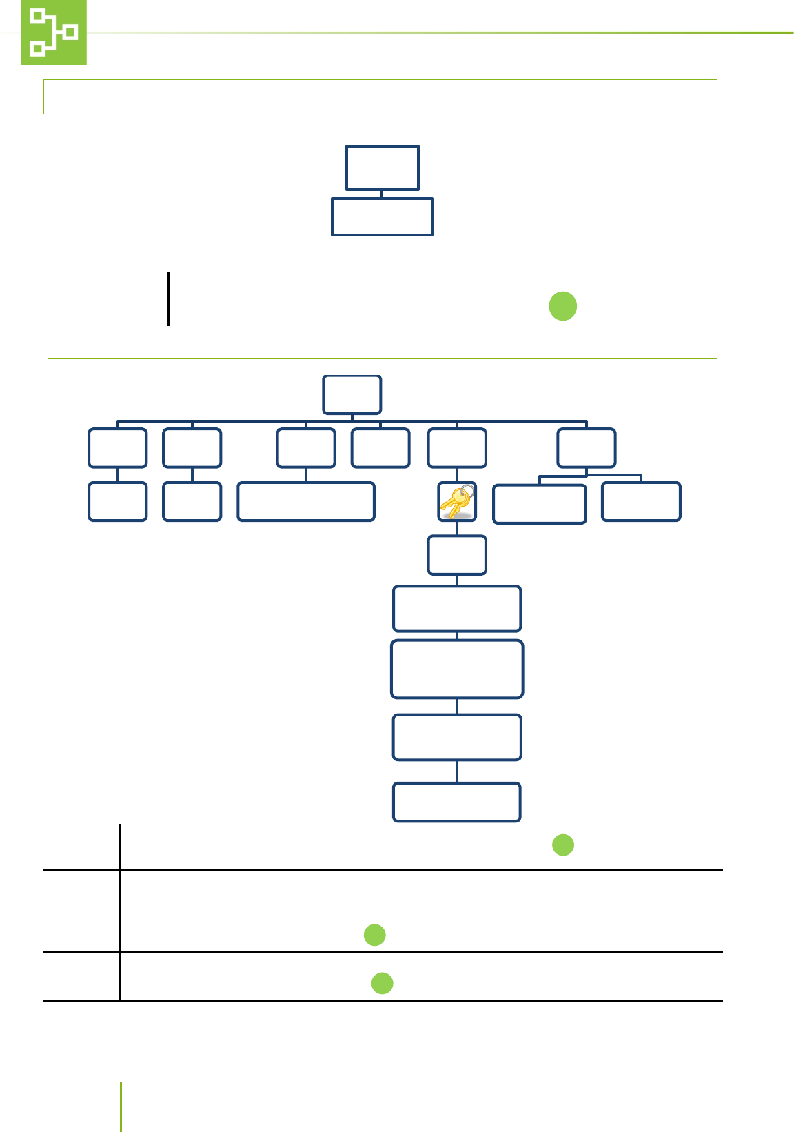
6.6 UNIT SETTINGS
RX Name Through this function it is possible to set the Unit name (ex. LAB 01). Press to confirm.
State
This function allows to set 2 different states: On Line and Off Line.
Whenever one unit is online, all information on alarms are transmitted from the TX on the unit to the
central receiver RX and alarms are logged by the system. If the unit is offline, the system “sees” the unit
but does not record any messages. Press to confirm.
Model
Through this function it is possible to choose two different models: RX with PSTN Dialer and Rx without
PSTN Dialer. To select either models, press
Conjuction Push whenever a record request has been sent by centralized receiver CX. Refer to paragraph
5.3 “RX, CX and TX connection”.
RF
RSSI: after confirming the password, press to see the received signal level (minimum 1 maximum
10).
ID Rx: after confirming the password, it is possible to insert the RX ID number between 0 and 225 using
the numerical keypad. Press to confirm
Check Tx network: after confirming the password, it is possible to check the Tx network in 2 different
ways:
1. Check Used Slot: only the Tx recorded will be checked.
2. Full Check: all the Tx recognized will be checked. Press to confirm.
Reset Rx network: after confirming the password, it is possible to reset the network:
1. Reset full TX network.
2. Cancel.
Unit
RX Name
Insert the
Unit's
name
State
On Line
Off Line
Model
RX with PSTN Dialer
RX without PSTN Dialer
Conjuction RF
RSSI
00/10
ID Rx
(Insert ID between 0 and
225)
Check Tx network
- Check Used Slot
- Full Check
Reset Rx network
- Reset full Tx network
- Cancel
TX POLLING ATTEMPTS
(3 TO 100)
Default
CONFIGURATION
RESET
FACTORY
SETTINGS
24
To select either function press
RF
TX polling attempts 3 to 100: after confirming the password it is possible to set the number of polling
attempts after which the system automatically triggers the “TX Missing” Alarm.
Default This function allows to go back to default CONFIGURATION or FACTORY SETTINGS
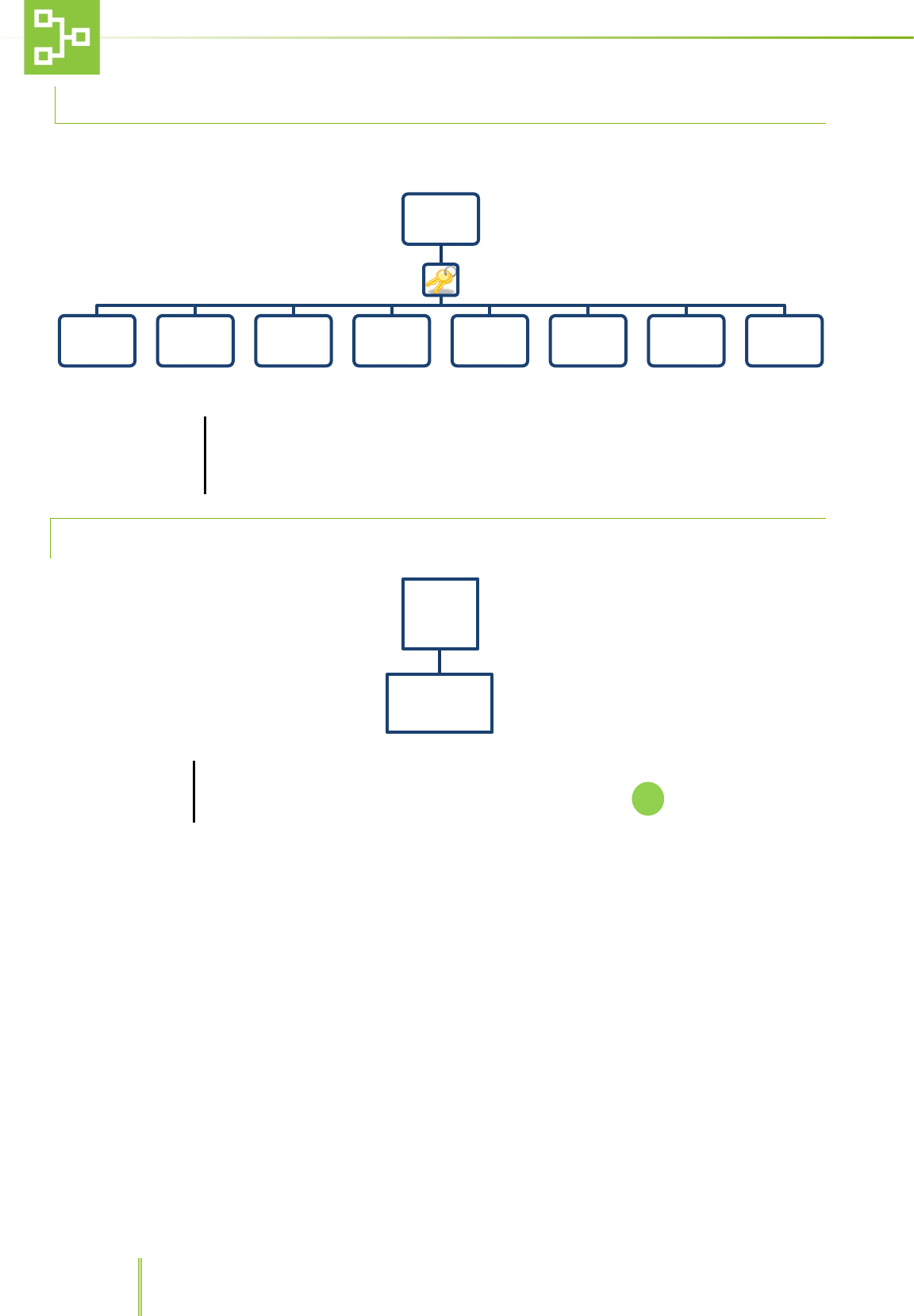
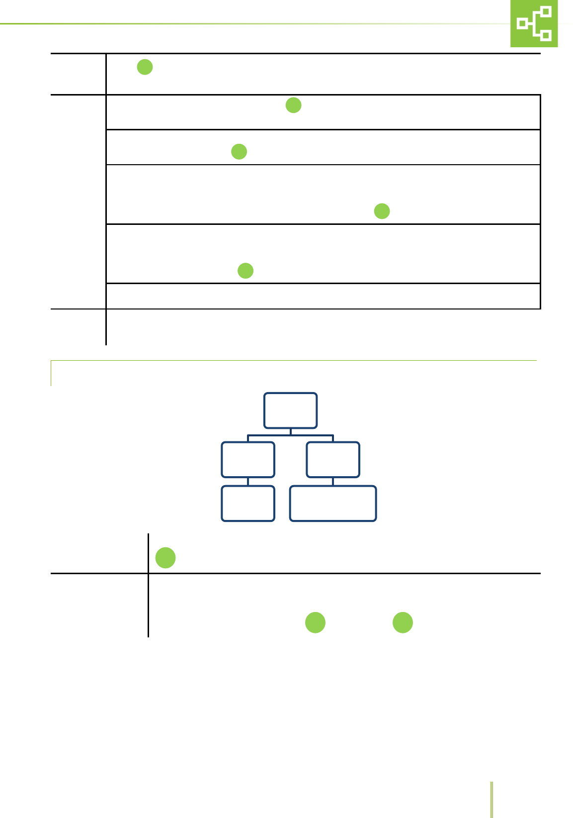
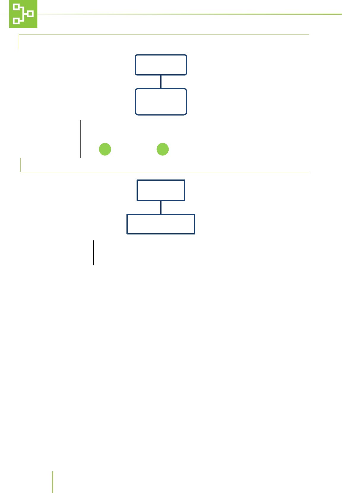
6.6.1 ALARM SETTING PAGE
Erase LOG
Through this function it is possible to erase all logged alarms or go back to the menu. Press
to confirm either function.
Type of Alarms
Through this function it is possible to set the priority for each alarm triggered by the
connected unit.
2 different priority levels may be set: CAT 1, high priority, CAT 2, low priority.
To save the right configuration press to cancel press
Alarms
Erase LOG
Erase all LOG
Cancel
TYPE OF
ALARMS
STD MODEL
CATEGORY
example:
AL 18 - CAT 1
IVC MODEL
CATEGORY
.......
MVC MODEL
CATEGORY
.......
ISO MODEL
CATEGORY
.......
DCC MODEL
CATEGORY
.......
F1
25
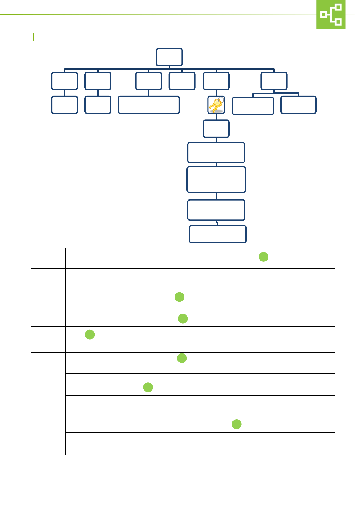
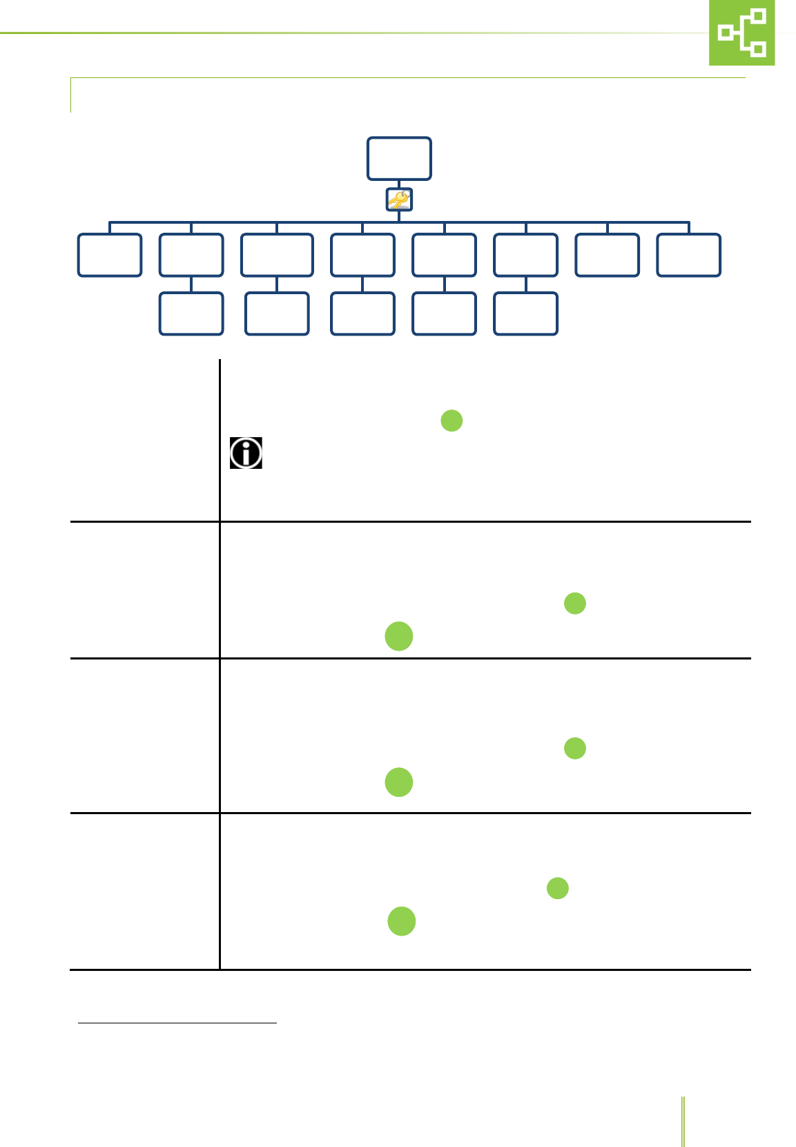
6.6.2 PSTN DIALER SETTINGS2
Enable
Through this function it is possible to enable/disable the PSTN dialer.
Choose between Yes or No and press
ENABLE THE DIALER AFTER CARRYING OUT THE SYSTEM SETTINGS IN ORDER TO
AVOID TRIGGERING ALARMS
Call Cat. 1
Through this function it is possible to save 5 different phone numbers (maximum 26 digits)
as a visual reminder of the numbers which the system will contact any time there is a HIGH
PRIORITY alarm (the system will call the numbers previously stored in the dialer). Please
refer to the dialer operating manual.
Enter the numbers using the numerical keyboard and press
To delete the number press
Call Cat.2
Through this function it is possible to save 4 different phone numbers (maximum 26 digits)
as a visual reminder of the numbers which the system will contact any time there is a LOW
PRIORITY alarm (the system will call the numbers previously stored in the dialer). Please
refer to the dialer operating manual.
Enter the numbers using the numerical keyboard and press
To delete the number press
Private Number
This page is used to record the RX line phone number (the system will call the numbers
previously stored in the dialer). Please refer to the dialer operating manual.
Enter the number using the numerical keypad and press
To delete the number, press
2 This menu is enabled only if the set model with PSTN dialer
PSTN
DIALER
Enable Call Cat.
1
Enter
number
Call Cat.
2
Enter
number
Private
Number
Enter
number
User
remote
code
Enter
number
Technical
remote
code
Enter
number
Test Tutorial
C
C
C
26
User Remote Code
Through this page it is possible to record (with 6 digits) and view the User remote code
which is needed to set up some functions in the dialer. Please refer to the dialer
operating manual.
Enter the code using the numerical keypad and press
To confirm the code, press , press to delete it.
Technical Remote Code
Through this page it is possible to record (with 6 digits) and view the Technical remote code
which is needed to set up some functions in the dialer. Please refer to the dialer
operating manual.
Enter the code using the numerical keypad and press
To confirm the code, press , press to delete it.
Test
Through this function it is possible to test the automatic dialer phone calls.
Run Cat. 1 (HIGH PRIORITY ) call.
Run Cat. 2 (LOW PRIORITY) call
Exit
Tutorial
PSTN DIALER INSTRUCTIONS FOR USE
C
C
C
F2
F1
27
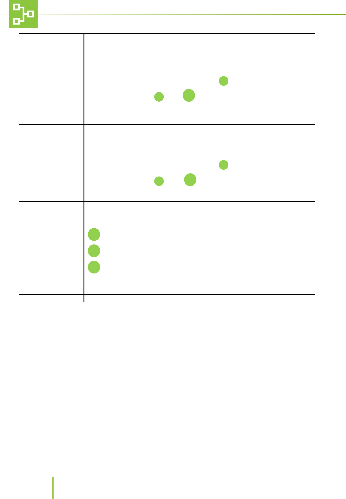
6.6.3 DIRECT OUTPUT
Enable
Through this function it is possible to ENABLE/DISABLE the direct output
Select the desired option and press
State
Through this function it is possible to set the output state:
OUTPUT NORMALLY OPEN
and
OUTPUT NORMALLY CLOSED.
Select the desired option and press
Test
Through this function it is possible to test the direct output:
Activate Direct Output Cat. 1
Activate Direct Output Cat. 2
Exit
Direct Output
Enable Enable Direct OutPut
Disable Direct Output
State Output Normally Opened
Output Normally Closed
Test
F1 Activate Direct Ouput Cat. 1
F2 Activate Direct Ouput Cat. 2
C Exit
C
F2
F1
28
6.6.4 PASSWORD SETTING
Insert new password
Through this function it is possible change password.
Enter the new password using the numerical field. Confirm and enter the password again.
Press to confirm, press to delete.
6.7 FIRMWARE
Country: Geographic area
Through this function it is possible to see:
− The firmware version loaded in the RX unit.
−
The geographic area setting RX network.
Password
Insert new password
Firmware &
Country
Country : Geographic area
C
29
6.8 TIME-OUT EXIT
Time-Out Exit3
Through this function it is possible to set the time-out value after which the system
automatically returns to the home page:
Enter the numerical value (minimum 5 second maximum 240 second)
To confirm, press . To delete, press .
To exit, press .
6.9 LANGUAGE SETTING PAGE
Language
Touch , after inserting the password it is possible to choose among 6 different
languages: Italian, French, English, Spanish and German and Portuguese.
To select the language press
3 This function is not enabled in the pages where it is possible to insert data (i.e.Hour/Date page)
Time-out
Exit
LANGUAGE
French
English
Spanish
Italian
German
Portuguese
F1
C
F3
30
7 RAS SYSTEM CENTRALISED RECEIVER(CX) SOFTWARE USER GUIDE
7.1 MAIN MENU
To open the main menu, press key F1.
ACCESS TO SOME FUNCTIONS IS ALLOWED TO SUPERVISORS ONLY.
MENU NAME
FUNCTION
UNIT
This function allows the user to view, record, delete and rename the units connected to the
system.
Select UNITS from the MENU list using the UP/DOWN arrows, then push to enter the sub-
menu.
ALARMS
This function allows to view the alarm log.
Select ALARMS from the MENU list using the UP/DOWN arrows, then push to enter the sub-
menu.
PSTN DIALER
This function allows the user to display the phone numbers to which the system has to send the
notifications according to the different alarm priority.
Select PSTN DIALER from the MENU list using the UP/DOWN arrows, then push to enter the
sub-menu.
MENU
UNIT ALARMS PSTN DIALER
31
7.2 UNIT MENU
MENU NAME
FUNCTION
VIEW
This function allows to check the connected RX state.
To check the connected transmitters (RX) connection status push
RECORD Record the RX unit
After confirming the password push .
The system will ask to press the
pushbutton on the RX unit transmitter to
record the unit to the RAS system. Refer
to paragraph 5.3 “RX, CX and TX
connection”.
CANCEL Returns to the Menu
ERASE After confirming the password push and delete the RX which you do not want to be recorded
any longer.
RENAME After confirming the password push and rename the unit
UNIT
VIEW RECORD
RECORD THE UNIT
RX CANCEL
ERASE
Unit
name
RENAME
Unit
name
32
7.3 ALARM FUNTIONS
This sub-menu allows acknowledge all the alarms raised by the system.
ALARMS
After selecting ALARMS it is possible to see the alarm log screen and check the reported alarm
status.
The alarm log displays the date and time when the alarm was triggered together with the TX unit
name and alarm code.
Icon √ next to the alarm message, indicates that the alarm was solved.
Icon indicates that the alarm is active.
The RAS records up to 100 alarms in FIFO Logic.
33
7.4 PSTN DIALER FUNCTIONS4
This sub-menu displays the set phone numbers to which the RAS system sends a warning call whenever one of the TX
units is triggering an alarm, as well as the user and technical remote codes and RX private phone line number.
The phone numbers must be set on the phone dialler (see the phone dialer IM). This sub-menu is only a
visualization menu that acts as a reminder for these numbers
CALL CAT. 1 After confirming the password it is possible to see 5 different phone numbers.
CALL CAT. 2 After confirming the password it is possible to see 4 different phone numbers
PRIVATE NUMBER Through this function it is possible to see a private number.
USER REMOTE CODE Through this function it is possible to see the user remote code with 6 digits.
TECHNICAL REMOTE CODE Through this function it is possible to see the technical remote code with 6 digits.
7.5 SETTINGS FUNCTIONS
To access the
settings functions,
push F4 on the
numerical key pad
After confirming the password it is possible to access different functions such as hour/date,
units, alarms, PSTN dialer, direct output, password and firmware & country.
4This menu is displayed only when the model is set with PSTN dialer
PSTN DIALER
Call Cat. 1 Call Cat. 2 Private
Number
User remote
code
Technical
remote code
SETTINGS
Hour Date Unit Alarms PSTN Dialer Direct
Output Password Firmware &
Country
Time-out
Exit
34
7.5.1 HOURS AND DATE SETTING
HOUR / DATE
After confirming the password and selecting hour/date it is possible to record the current time
and date using the numerical keypad. To confirm the setting push
7.6 UNIT SETTINGS
CX Name Through this function it is possible to set the Unit name (ex. LAB 01). Press to confirm.
State
This function allows to set 2 different states: On Line and Off Line.
Whenever one unit is online, all information on alarms are transmitted from the TX on the unit to the
central receiver RX and alarms are logged by the system. If the unit is offline, the system “sees” the unit
but does not record any messages. Press to confirm.
Model
Through this function it is possible to choose two different models: RX with PSTN Dialer and Rx without
PSTN Dialer. To select either models, press
Hour Date
Date: __/__/__
Hour: __/__/__
Unit
CX Name
Insert the
Unit name
State
On Line
Off Line
Model
CX with PSTN Dialer
CX without PSTN Dialer
Conjuction RF
RSSI
00/10
ID Cx
(Insert ID between 0 and
225)
Check Rx network
- Check Used Slot
- Full Check
Reset Cx network
- Reset full Cx network
- Cancel
TX POLLING ATTEMPTS
(3 TO 100)
Default
CONFIGURATION
RESET
FACTORY
SETTINGS
35
Conjuction Push whenever a record request has been sent by centralized receiver CX. Refer to paragraph
5.3 “RX, CX and TX connection”.
RF
RSSI: after confirming the password, press to see the received signal level (minimum 1 maximum
10).
ID Rx: after confirming the password, it is possible to insert the RX ID number between 0 and 225 using
the numerical keypad. Press to confirm
Check Tx network: after confirming the password, it is possible to check the Tx network in 2 different
ways:
3. Check Used Slot: only the Tx recorded will be checked.
4. Full Check: all the Tx recognized will be checked. Press to confirm.
Reset Rx network: after confirming the password, it is possible to reset the network:
3. Reset full TX network.
4. Cancel.
To select either function press
TX polling attempts 3 to 100: after confirming the password it is possible to set the number of polling
attempts after which the system automatically triggers the “TX Missing” Alarm.
Default This function allows to go back to default CONFIGURATION or FACTORY SETTINGS
7.6.1 ALARM SETTING PAGE
Erase LOG
Through this function it is possible to erase all logged alarms or go back to the menu. Press
to confirm either function.
Type of Alarms
Through this function it is possible to set the priority for each alarm triggered by the
connected unit.
2 different priority levels may be set: CAT 1, high priority, CAT 2, low priority.
To save the right configuration press to cancel press
Alarms
Erase LOG
Erase all LOG
Cancel
Type of
Alarms
AL. 31 - Cat. 1/2
AL. 32 - Cat. 1/2
F1
36
7.6.2 PSTN DIALER SETTINGS
Enable
Through this function it is possible to enable/disable the PSTN dialer.
Choose between Yes or No and press
ENABLE THE DIALER AFTER CARRYING OUT THE SYSTEM SETTINGS IN ORDER TO AVOID
TRIGGERING ALARMS
Call Cat. 1
Through this function it is possible to save 5 different phone numbers (maximum 26 digits) as a
visual reminder of the numbers which the system will contact any time there is a HIGH PRIORITY
alarm (the system will call the numbers previously stored in the dialer). Please refer to the
dialer operating manual.
Enter the numbers using the numerical keyboard and press
To delete the number press
Call Cat.2
Through this function it is possible to save 4 different phone numbers (maximum 26 digits) as a
visual reminder of the numbers which the system will contact any time there is a LOW PRIORITY
alarm (the system will call the numbers previously stored in the dialer). Please refer to the
dialer operating manual.
Enter the numbers using the numerical keyboard and press
To delete the number press
Private Number
This page is used to record the RX line phone number (the system will call the numbers
previously stored in the dialer). Please refer to the dialer operating manual.
Enter the number using the numerical keypad and press
To delete the number, press
User Remote Code
Through this page it is possible to record(with 6 digits) and view the User remote code which is
needed to set up some functions in the dialer. Please refer to the dialer operating manual.
Enter the code using the numerical keypad and press
To confirm the code, press , press to delete it.
PSTN
DIALER
Enable Call Cat.
1
Enter
number
Call Cat.
2
Enter
number
Private
Number
Enter
number
User
remote
code
Enter
number
Technical
remote
code
Enter
number
Test Tutorial
C
C
C
C
37
Technical Remote
Code
Through this page it is possible to record (with 6 digits) and view the Technical remote code
which is needed to set up some functions in the dialer. Please refer to the dialer operating
manual.
Enter the code using the numerical keypad and press
To confirm the code, press , press to delete it.
Test
Through this function it is possible to test the automatic dialer phone calls.
Run Cat. 1 (HIGH PRIORITY ) call.
Run Cat. 2 (LOW PRIORITY) call
Exit
Tutorial PSTN DIALER INSTRUCTIONS FOR USE
7.6.3 DIRECT OUTPUT
Enable
Through this function it is possible to ENABLE/DISABLE direct output
Select the desired option and press
State
Through this function it is possible to set the output state:
OUTPUT NORMALLY OPEN
and
OUTPUT NORMALLY CLOSED.
Select the desired option and press
Test
Through this function it is possible to test the direct output:
Activate Direct Output Cat. 1
Activate Direct Output Cat. 2
Exit
Direct
Output
Enable
Enable Direct OutPut
Disable Direct Output
State
Output Normally Opened
Output Normally Closed
Teste
F1 Activate Direct Ouput Cat. 1
F2 Activate Direct Ouput Cat. 2
C Exit
C
C
F2
F1
C
F2
F1
38
7.6.4 PASSWORD SETTING
Insert new password
To change password:
Enter the new password using the numerical field. Confirm and enter the new password
again.
Press to confirm, press to delete.
7.7 FIRMWARE
Country: Geographic area
Through this function it is possible to see:
− The firmware version loaded in the RX unit.
− The geographic area setting RX network.
Password
Insert new
password
Firmware &
Country
Country : Geographic area
C
39
7.8 TIME-OUT EXIT
Time-Out Exit5
To set the time-out value after which the system automatically returns to the home page:
Enter the numerical value (minimum 5 second maximum 240 second)
To confirm, press . To delete, press .
To exit, press .
7.9 LANGUAGE SETTING PAGE
Language
Touch , after inserting the password it is possible to choose among 6 different languages
such as Italian, French, English, Spanish, German and Portuguese.
To select the language, press
5 This function is not enabled in the pages where it is possible to insert data (i.e.Hour/Date page)
Time-Out
Exit
LANGUAGE
French English Spanish Italian German Portuguese
F1
C
F3
8 ALARMS REPORTED BY THE SYSTEM
8.1 ALARMS RAISED BY THE TRANSMITTER
(TX)
The RAS is to be connected to the power supply
protected by suitable protections in compliance with
laws and regulations in force in the country where
the machine is installed.
Hereunder is the list of the alarm messages which
might be sent by the transmitter (TX) to the RX,
according to the equipment type.
NOTE: Refer to the equipment user manual for a
complete troubleshooting.
IVC/MVC
AL01 MIN SUPPLY FLOW
AL02 MAX SUPPLY FLOW
AL03 MIN EXHAUST FLOW
AL04 MAX EXHAUST FLOW
AL05 MIN PRESSURE
AL06 MAX PRESSURE
AL07 MIN TEMPERATURE
AL08 MAX TEMPERATURE
AL09 MIN RH%
AL10 MAX RH%
AL11 REPL SUPPLY HEPA
AL12 REPL EXHAUST HEPA
AL13 SUPPLY AIR FLOW
AL14 EXHAUST AIR FLOW
AL16 FLOODING ALARM
AL23 SUPPLY HOUR-COUNTER WARNING
AL24 EXHAUST HOUR-COUNTER WARNING
ISOCAGE
AL01 MIN PRESSURE
AL02 MAX PRESSURE
AL03 AIRFLOW
AL04 REPL SUPPLY HEPA
AL05 REPL EXHAUST HEPA
AL06 UPS BATTERY LOW
AL07 UPS FAULT
AL08 MIN TEMPERATURE
AL09 MAX TEMPERATURE
AL10 MIN HUMIDITY
AL11 MAX HUMIDITY
AL23 SUPPLY HOUR-COUNTER WARNING
AL24 EXHAUST HOUR-COUNTER WARNING
DCC
AL03 AIRFLOW
AL05 REPL EXHAUST HEPA
AL06 UPS BATTERY LOW
AL07 UPS FAULT
AL08 MIN TEMPERATURE
AL09 MAX TEMPERATURE
AL10 MIN HUMIDITY
AL11 MAX HUMIDITY
AL24 EXHAUST HOUR-COUNTER WARNING
GENERAL
AUX 1 ALARM
AUX 2 ALARM
AL19 TX POWER FAILURE
AL20 TX MISSING
AL21 485 COMMUNICATION FAILURE
TX OFFLINE
8.2 ALARMS RAISED BY THE RX
RX Power failure
RX Missing
RX Offline

2-00003572-0-02EN