Tecom Co BT3010 Spread Spectrum Transmitter Module User Manual Installation Guide and User s Manual
Tecom Co Ltd Spread Spectrum Transmitter Module Installation Guide and User s Manual
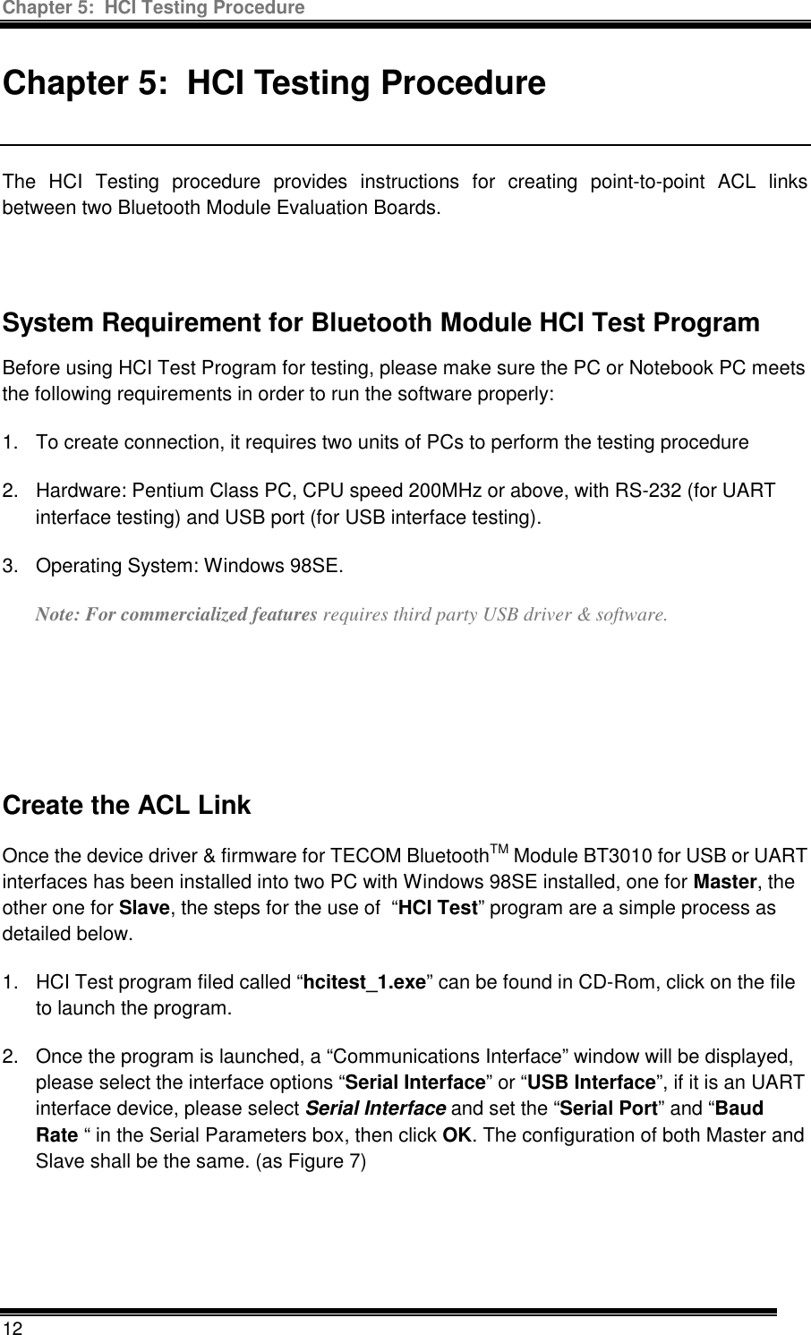
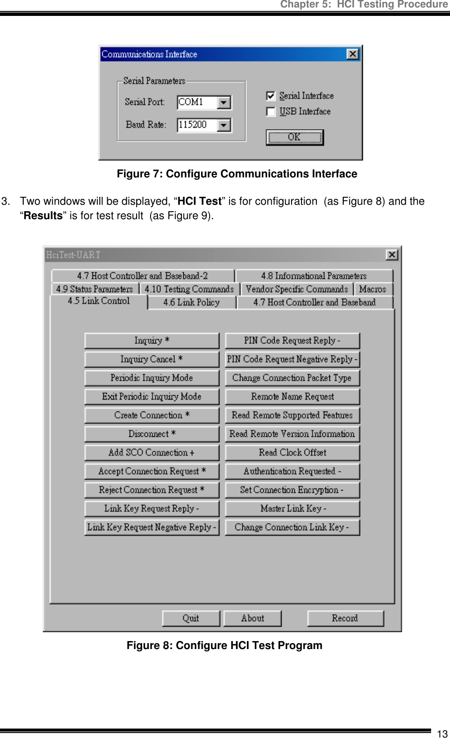
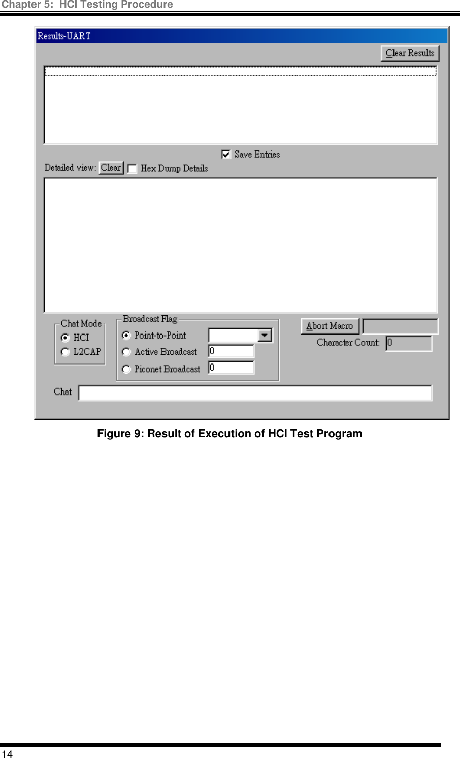
Tecom Co >
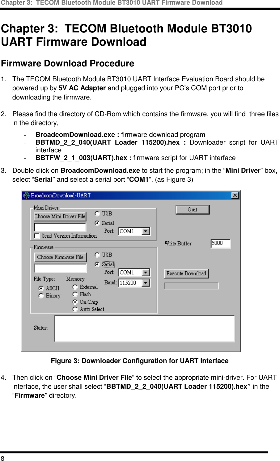
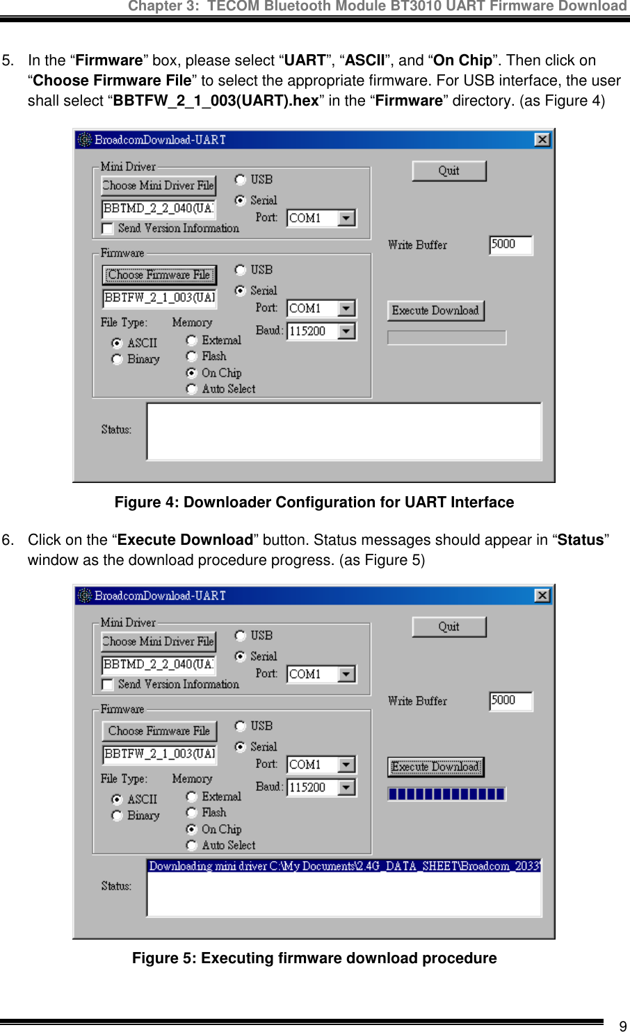
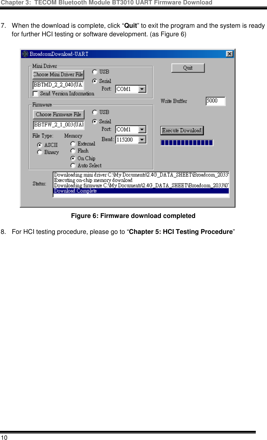
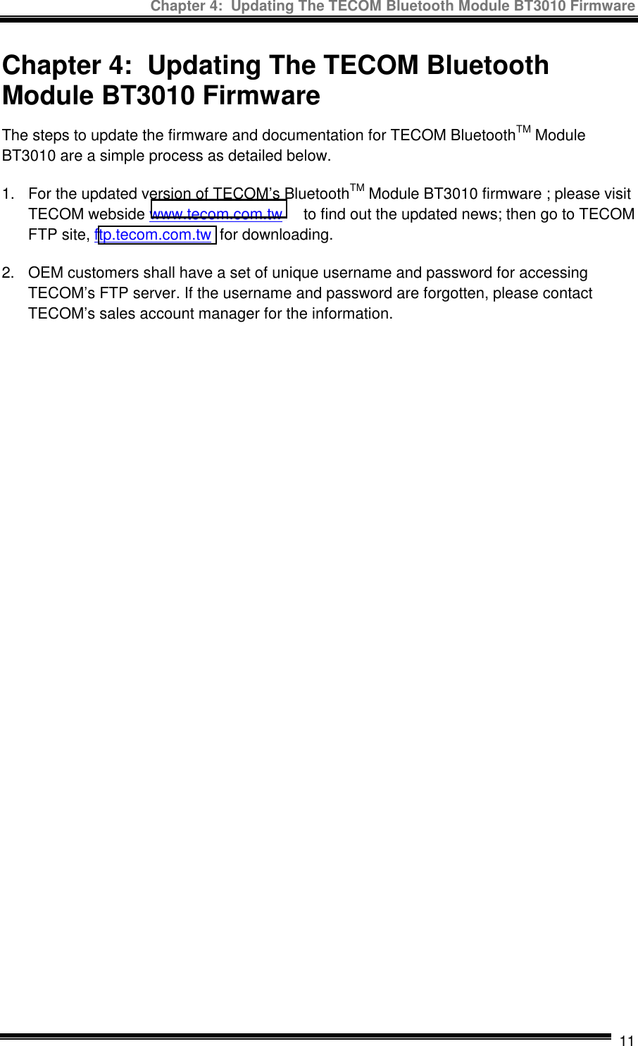
Contents
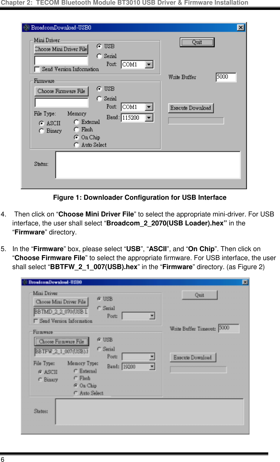
- 1. Manual guide 1 revised
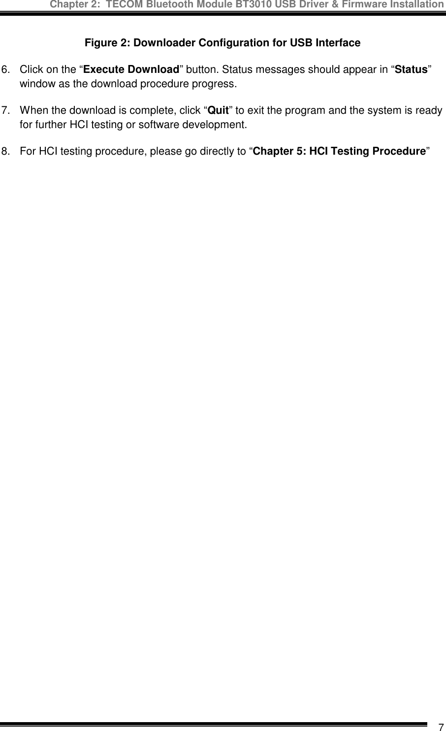
- 2. Manual guide 2
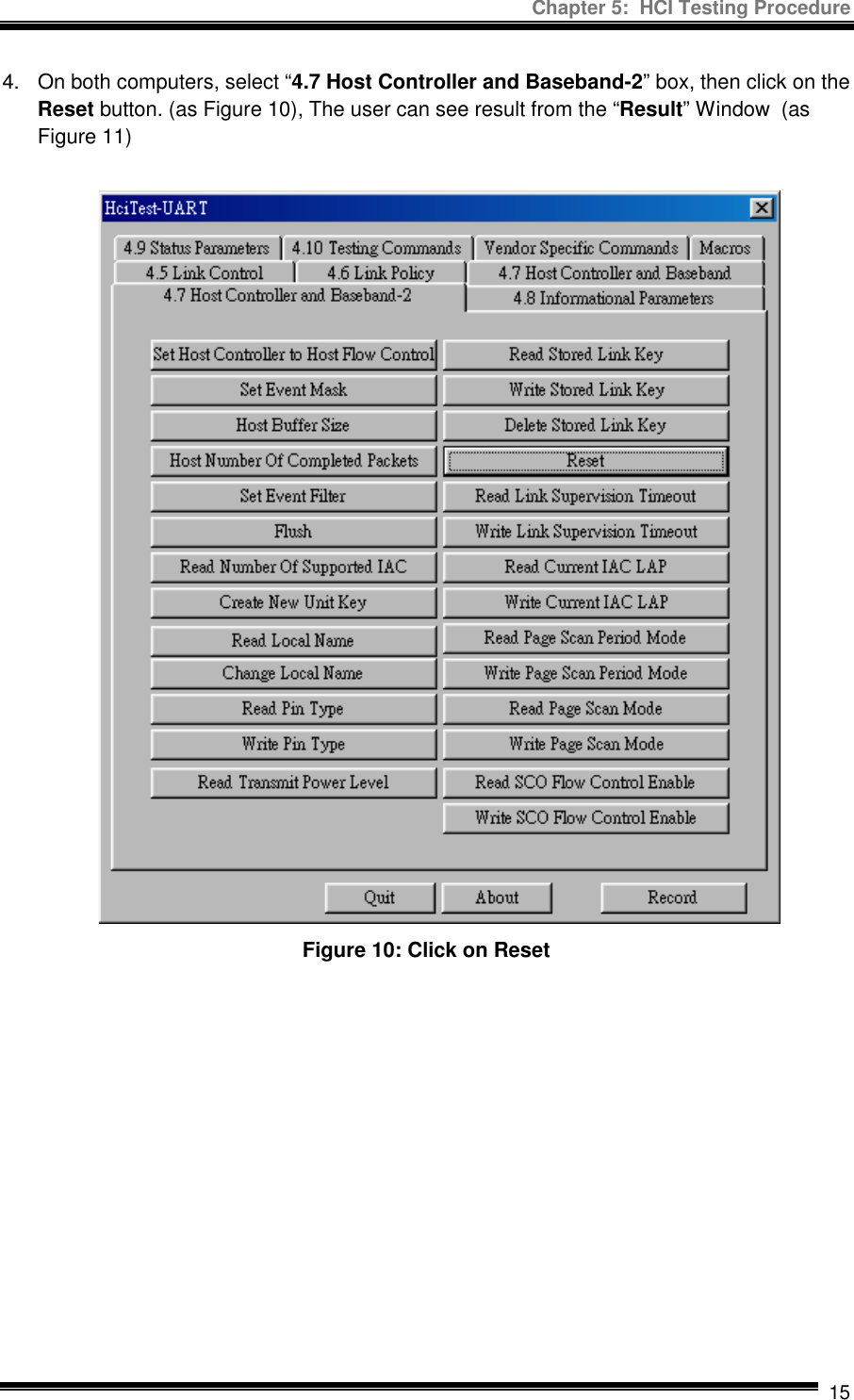
Manual guide 2