Tecom Co BT3010 Spread Spectrum Transmitter Module User Manual Installation Guide and User s Manual
Tecom Co Ltd Spread Spectrum Transmitter Module Installation Guide and User s Manual
Tecom Co >
Contents
- 1. Manual guide 1 revised
- 2. Manual guide 2
Manual guide 2

TECOM CO., LTD.
23, R&D ROAD 2, SBIP
HSIN-CHU, TAIWAN, ROC
PHONE: +886-3-577-5141
FAX: +886-3-579-7196
Version: 0.8 / Issued: 2001/9/15
Firmware User’s Manual
for
BT3010 Bluetooth Module
(Preliminary for Sample Evaluation Stage)

1
About This Manual
This manual provides a comprehensive firmware user’s manual for TECOM BluetoothTM
Module BT3010. It has been organized in such a way to make it easy to follow by users
worldwide. In order to ensure optimal comprehension, the following list provides brief
descriptions of the formatting styles used throughout this manual.
! Commands: Commands are always referred to by using the word “click” before them.
These commands are always shown as bold-faced words. For example, click Next, click
OK, or click Cancel.
! Names of Windows (Dialog Boxes): The names of the windows (also referred to as
dialog boxes) that appear on the PC screen are always referred to in quotes. For
example, the “Setup Complete” window.
! Names of Options in Windows: The names of options to choose from inside the
windows that appear on the PC screen are always referred to in italics. For example,
choose the Yes, I want to restart my computer now option from the window.
! Notes: In some cases, preparatory or cautionary information is needed before
proceeding onto the next step in an installation process. This kind of information is
provided in the form of notes, which are always referred to in bold-faced and italicized
letters. For example, Note: To access the TECOM Control Panel, the driver must be running.
Also, make sure the BluetoothTM USB evaluation board is plugged into the notebook.

2
Preface
The TECOM BluetoothTM Module BT3010 Manual
This manual contains information regarding the installation, operation, and configuration of
the TECOM BluetoothTM Module BT3010. Additionally, it outlines the use of the “Firmware
Downloader” and “HCI Test” Application.
The following chapters are included in this manual:
• Chapter 1: “Overview” offers a brief description of Bluetooth and the features of the
TECOM BluetoothTM Module BT3010.
• Chapter 2: “TECOM BluetoothTM Module BT3010 USB Driver and Firmware
Installation” describes the steps for installing the USB driver for TECOM BluetoothTM
Module BT3010 USB Evaluation Board and details of the firmware download procedure.
• Chapter 3: “TECOM BluetoothTM Module BT3010 UART Evaluation Board Firmware
Donwload” describes the steps for downloading the TECOM BluetoothTM Module BT3010
UART firmware.
• Chapter 4: “Updating the TECOM BluetoothTM Module BT3010 Firmware” details the
procedure for updating to a new version of the Bluetooth firmware.
• Chapter 5: “HCI Testing Procedule” describes how to search for the other Bluetooth
devices and create Bluetooth connections between devices.
• Chapter 6: “Software Uninstall” provides detailed steps for removing the TECOM
BluetoothTM Module BT3010 USB driver from the PC.
• Chapter 7: “Trouble Shooting” answers some problems that might be encountered in
installation and manipulation.

Chapter 1: Overview
3
Chapter 1: Overview
About BluetoothTM
Bluetooth is a worldwide standard for the wireless communication of data & voice services
between two devices. Bluetooth technology eliminates wires and cables between both
stationary and mobile devices, provides the possibility of ad hoc networks and delivers the
ultimate synchronicity between all your personal devices.
The Bluetooth wireless technology has been adopted not only by all major players in the
telecom, computer and home entertainment industry, but also in such many other areas as
the automotive industry and health care, automation and toys, etc. - almost all sectors of the
economy.
Features
The TECOM BluetoothTM Module BT3010 provides the following features:
• Compliant with Bluetooth Specification V.1.1
• Supports USB, UART, and PCM Interfaces
• Evaluation board is available for USB or UART interface
• Supports 0 to 20dBm Output Power (Support Class 1, 2, 3)
• Operating distance up to 100 meters
• Supports point-to-multipoint connections
• Firmware support up to lower HCI layer
• Supports data rates up to 723 Kbps
Firmware Support
The TECOM BluetoothTM Module BT3010 provides the following software for evaluation &
software development:
• Including firmware for the host control interfaces (for USB, UART interfaces), HCI, and
the link manager, LM. The firmware is provided in the CD-R.
• A firmware donwloader, USB driver (for testing purpose only), and HCI Test program are
available. Note: USB Test driver is only provided for test & evaluation purpose, for
commercial use, please contact third party software providers for solution.

Chapter 2: TECOM Bluetooth Module BT3010 USB Driver & Firmware Installation
4
Chapter 2: TECOM Bluetooth Module BT3010
USB Driver & Firmware Installation
Bluetooth Module Evaluation Board for USB Interface System
Requirement
Before installing the TECOM BluetoothTM Module BT3010 USB driver for evaluation, please
make sure the PC or Notebook PC meets the following requirements in order to run the
software properly:
1. Hardware: Pentium Class PC, CPU speed 200MHz or above, with USB port.
2. Operating System: Windows 98SE.
Note: For commercialized features requires third party driver & software.

Chapter 2: TECOM Bluetooth Module BT3010 USB Driver & Firmware Installation
5
Driver Installation Procedure
Note: Before downloading the firmware to BT3010 Bluetooth Module USB Evaluation Board, the
system needs to install the provided USB driver first and followed by downloading the firmware for
USB interface, then the user shall follow HCI testing procedure to begin the HCI testing.
1. The TECOM Bluetooth Module BT3010 USB Interface Evaluation Board should be
plugged into your PC’s USB port prior to installing the driver.
2. The PC automatically detects the device and a window will be displayed to request the
user to install the driver. Please follow the standard hardware driver installation
procedure. When the PC request the user to locate the source of driver files, please find
the CD-Rom which contains the firmware, then go to the directory “USB Drivers”, then
select the filename “bcbtusb.inf” and click Next to complete the driver installation
process.
3. Before using the firmware downloader, the user needs to adjust the device configuration
first to allow the firmware downloader program to download the firmware without creating
the conflict between the default setting of configuration.
4. For changing the device configuration, please go to “Control Panel” and select
“System”, then go to “Device Manager” and click on “Blutonium Devices”
5. The next step is to find “Broadcom Blutonium Composite Device” under the directory
of “Blutonium Devices” and click on the “Content”. Locate “Blutonium Settings” under
the content of “Broadcom Blutonium Composite Device” then deselect “Download
Firmware”.
6. By completing the above process, the firmware download program is ready to download
the firmware for further testing and software development.
Firmware Download Procedure
1. The TECOM Bluetooth Module BT3010 USB Interface Evaluation Board should be still
plugged into your PC’s USB port prior to downloading the firmware.
2. Please find the directory of CD-Rom which contains the firmware, you will find three files
in the directory,
- BroadcomDownload.exe : firmware download program
- Broadcom_2_2070(USB Loader).hex : Downloader script for USB interface
- BBTFW_2_1_007(USB).hex : firmware script for USB interface
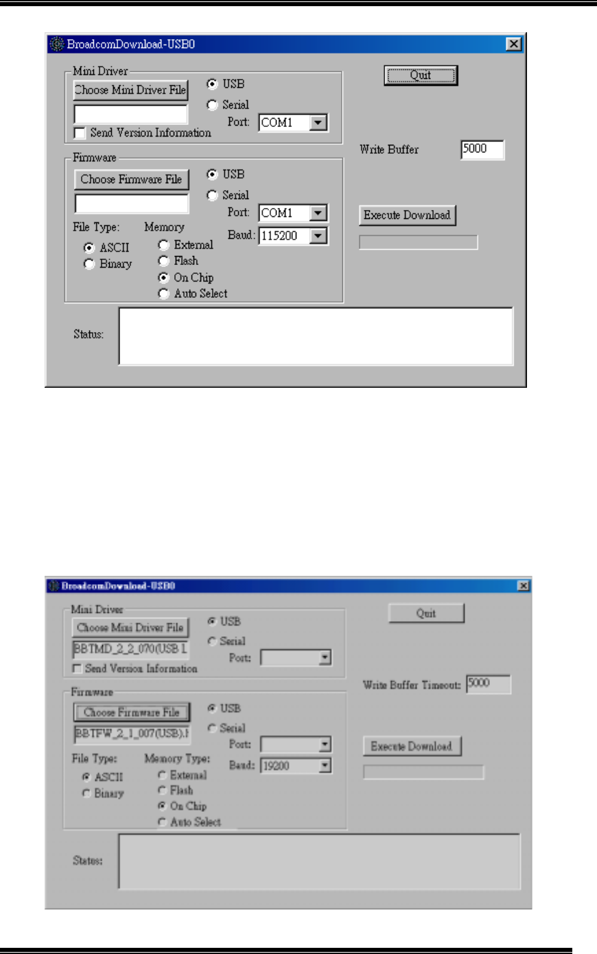
3. Double click on BroadcomDownload.exe to start the program. In the “Mini Driver” box,
select “USB” and deselect “Send Version Information.” (as Figure 1)
Chapter 2: TECOM Bluetooth Module BT3010 USB Driver & Firmware Installation
6
Figure 1: Downloader Configuration for USB Interface
4. Then click on “Choose Mini Driver File” to select the appropriate mini-driver. For USB
interface, the user shall select “Broadcom_2_2070(USB Loader).hex” in the
“Firmware” directory.
5. In the “Firmware” box, please select “USB”, “ASCII”, and “On Chip”. Then click on
“Choose Firmware File” to select the appropriate firmware. For USB interface, the user
shall select “BBTFW_2_1_007(USB).hex” in the “Firmware” directory. (as Figure 2)

Chapter 2: TECOM Bluetooth Module BT3010 USB Driver & Firmware Installation
7
Figure 2: Downloader Configuration for USB Interface
6. Click on the “Execute Download” button. Status messages should appear in “Status”
window as the download procedure progress.
7. When the download is complete, click “Quit” to exit the program and the system is ready
for further HCI testing or software development.
8. For HCI testing procedure, please go directly to “Chapter 5: HCI Testing Procedure”
Chapter 3: TECOM Bluetooth Module BT3010 UART Firmware Download
8
Chapter 3: TECOM Bluetooth Module BT3010
UART Firmware Download
Firmware Download Procedure
1. The TECOM Bluetooth Module BT3010 UART Interface Evaluation Board should be
powered up by 5V AC Adapter and plugged into your PC’s COM port prior to
downloading the firmware.
2. Please find the directory of CD-Rom which contains the firmware, you will find three files
in the directory,
- BroadcomDownload.exe : firmware download program
- BBTMD_2_2_040(UART Loader 115200).hex : Downloader script for UART
interface
- BBTFW_2_1_003(UART).hex : firmware script for UART interface
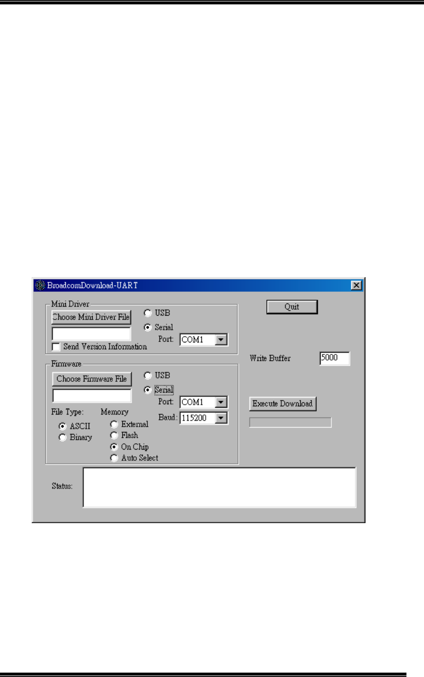
3. Double click on BroadcomDownload.exe to start the program; in the “Mini Driver” box,
select “Serial” and select a serial port “COM1”. (as Figure 3)
Figure 3: Downloader Configuration for UART Interface
4. Then click on “Choose Mini Driver File” to select the appropriate mini-driver. For UART
interface, the user shall select “BBTMD_2_2_040(UART Loader 115200).hex” in the
“Firmware” directory.
Chapter 3: TECOM Bluetooth Module BT3010 UART Firmware Download
9
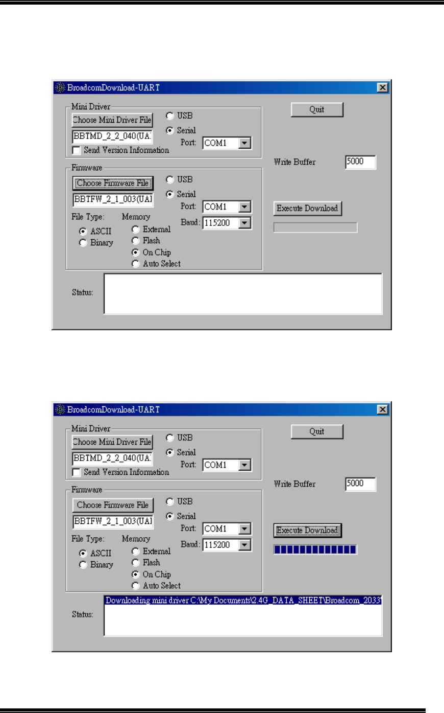
5. In the “Firmware” box, please select “UART”, “ASCII”, and “On Chip”. Then click on
“Choose Firmware File” to select the appropriate firmware. For USB interface, the user
shall select “BBTFW_2_1_003(UART).hex” in the “Firmware” directory. (as Figure 4)
Figure 4: Downloader Configuration for UART Interface
6. Click on the “Execute Download” button. Status messages should appear in “Status”
window as the download procedure progress. (as Figure 5)
Figure 5: Executing firmware download procedure
Chapter 3: TECOM Bluetooth Module BT3010 UART Firmware Download
10
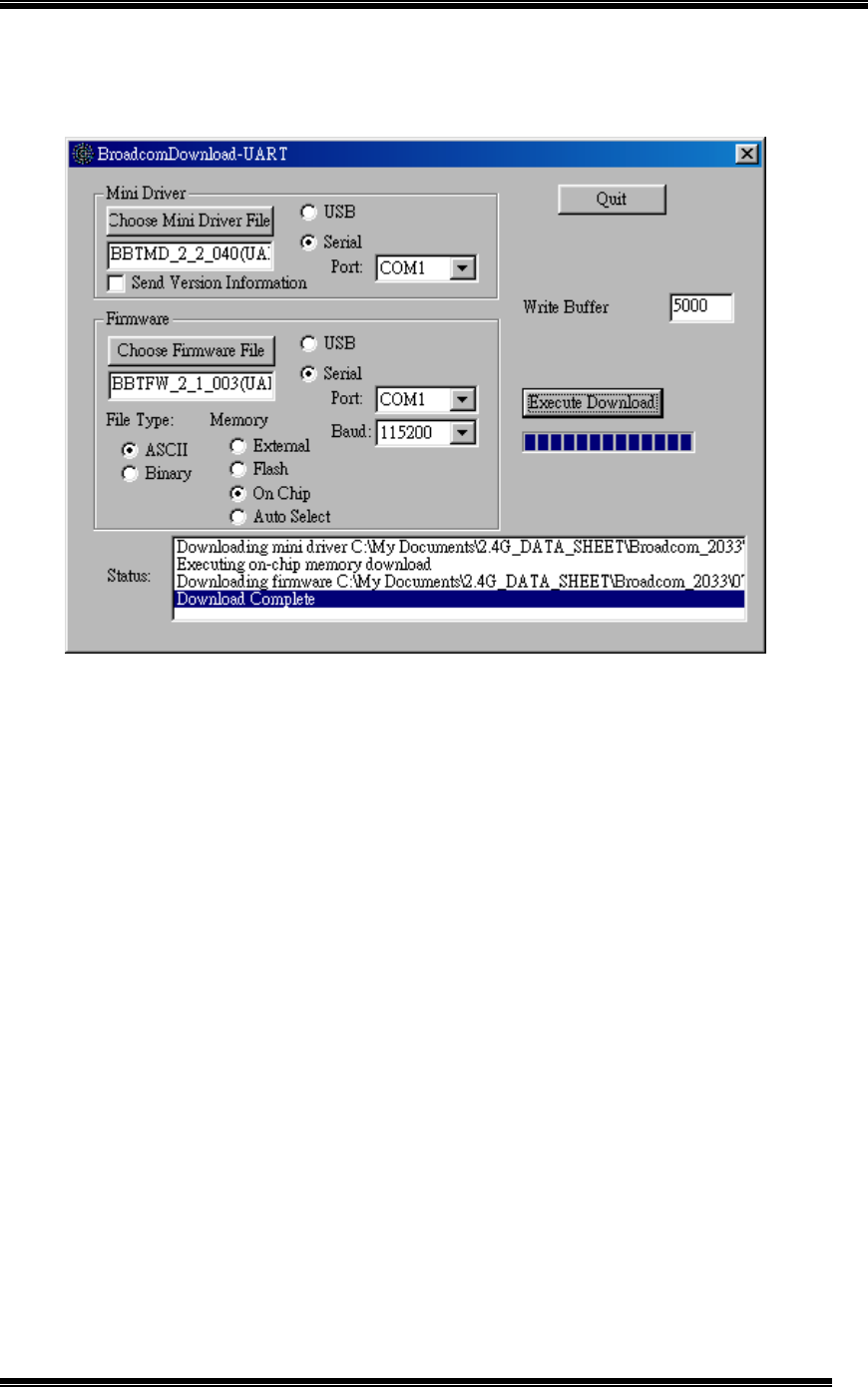
7. When the download is complete, click “Quit” to exit the program and the system is ready
for further HCI testing or software development. (as Figure 6)
Figure 6: Firmware download completed
8. For HCI testing procedure, please go to “Chapter 5: HCI Testing Procedure”

Chapter 4: Updating The TECOM Bluetooth Module BT3010 Firmware
11
Chapter 4: Updating The TECOM Bluetooth
Module BT3010 Firmware
The steps to update the firmware and documentation for TECOM BluetoothTM Module
BT3010 are a simple process as detailed below.
1. For the updated version of TECOM’s BluetoothTM Module BT3010 firmware ; please visit
TECOM webside www.tecom.com.tw to find out the updated news; then go to TECOM
FTP site, ftp.tecom.com.tw for downloading.
2. OEM customers shall have a set of unique username and password for accessing
TECOM’s FTP server. If the username and password are forgotten, please contact
TECOM’s sales account manager for the information.

Chapter 5: HCI Testing Procedure
12
Chapter 5: HCI Testing Procedure
The HCI Testing procedure provides instructions for creating point-to-point ACL links
between two Bluetooth Module Evaluation Boards.
System Requirement for Bluetooth Module HCI Test Program
Before using HCI Test Program for testing, please make sure the PC or Notebook PC meets
the following requirements in order to run the software properly:
1. To create connection, it requires two units of PCs to perform the testing procedure
2. Hardware: Pentium Class PC, CPU speed 200MHz or above, with RS-232 (for UART
interface testing) and USB port (for USB interface testing).
3. Operating System: Windows 98SE.
Note: For commercialized features requires third party USB driver & software.
Create the ACL Link
Once the device driver & firmware for TECOM BluetoothTM Module BT3010 for USB or UART
interfaces has been installed into two PC with Windows 98SE installed, one for Master, the
other one for Slave, the steps for the use of “HCI Test” program are a simple process as
detailed below.
1. HCI Test program filed called “hcitest_1.exe” can be found in CD-Rom, click on the file
to launch the program.
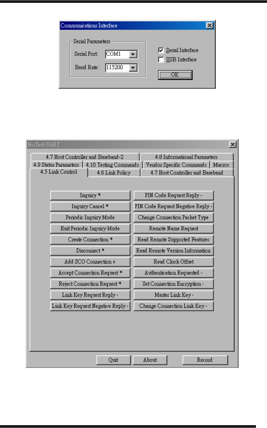
2. Once the program is launched, a “Communications Interface” window will be displayed,
please select the interface options “Serial Interface” or “USB Interface”, if it is an UART
interface device, please select Serial Interface and set the “Serial Port” and “Baud
Rate “ in the Serial Parameters box, then click OK. The configuration of both Master and
Slave shall be the same. (as Figure 7)
Chapter 5: HCI Testing Procedure
13
Figure 7: Configure Communications Interface
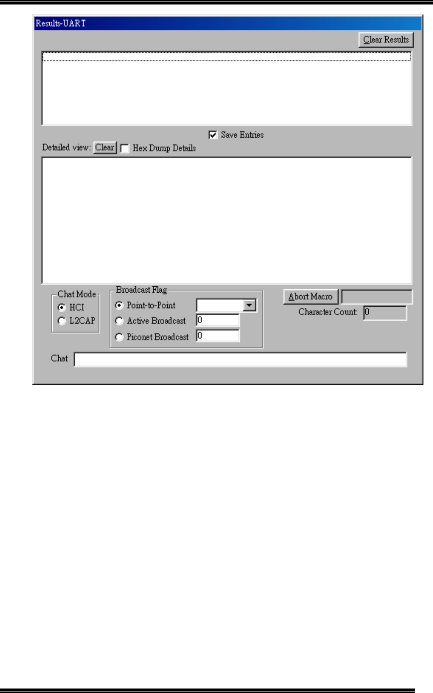
3. Two windows will be displayed, “HCI Test” is for configuration (as Figure 8) and the
“Results” is for test result (as Figure 9).
Figure 8: Configure HCI Test Program
Chapter 5: HCI Testing Procedure
14
Figure 9: Result of Execution of HCI Test Program
Chapter 5: HCI Testing Procedure
15
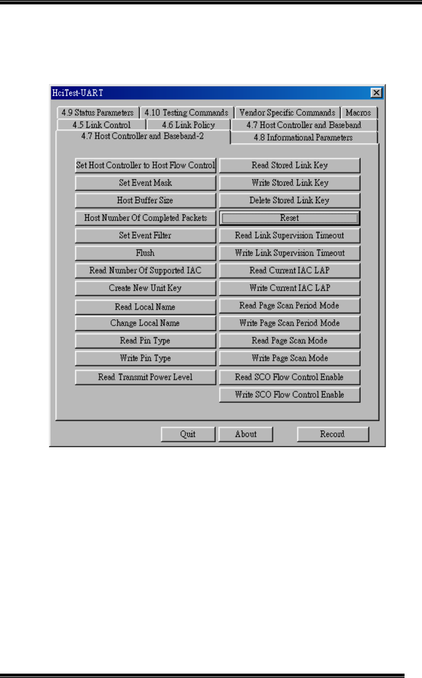
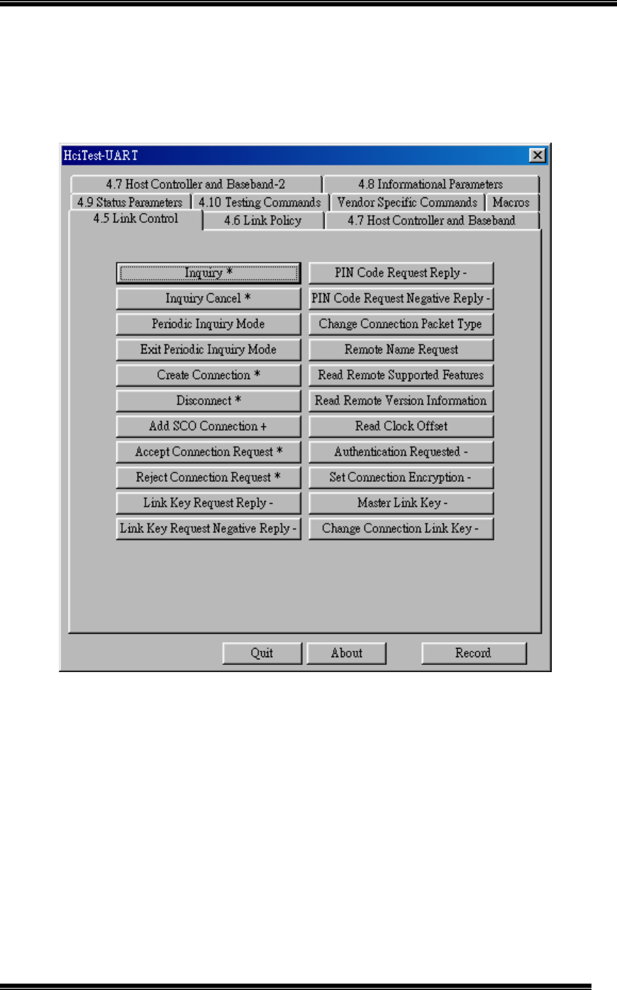
4. On both computers, select “4.7 Host Controller and Baseband-2” box, then click on the
Reset button. (as Figure 10), The user can see result from the “Result” Window (as
Figure 11)
Figure 10: Click on Reset
Chapter 5: HCI Testing Procedure
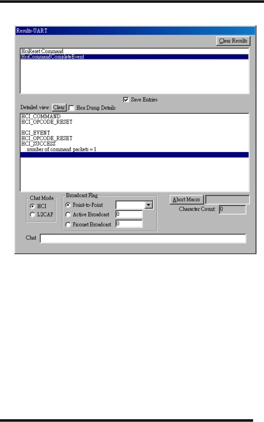
16
Figure 11: Show test result
Chapter 5: HCI Testing Procedure
17
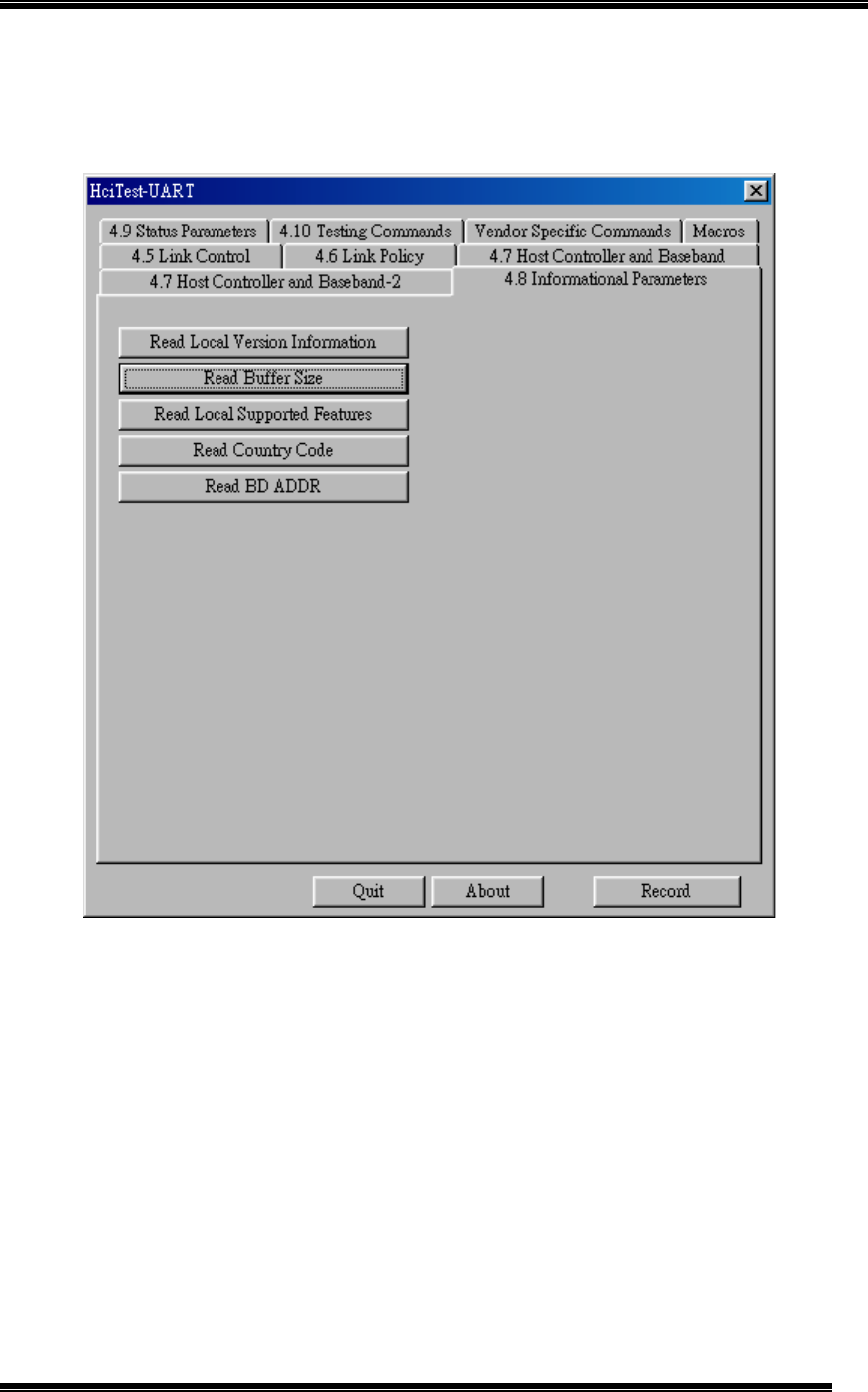
5. On both computers, select “4.8 Information Parameters” box, then click on the ”Read
Buffer Size“ button. (as Figure 12).
Figure 12: Show test result
Chapter 5: HCI Testing Procedure
18
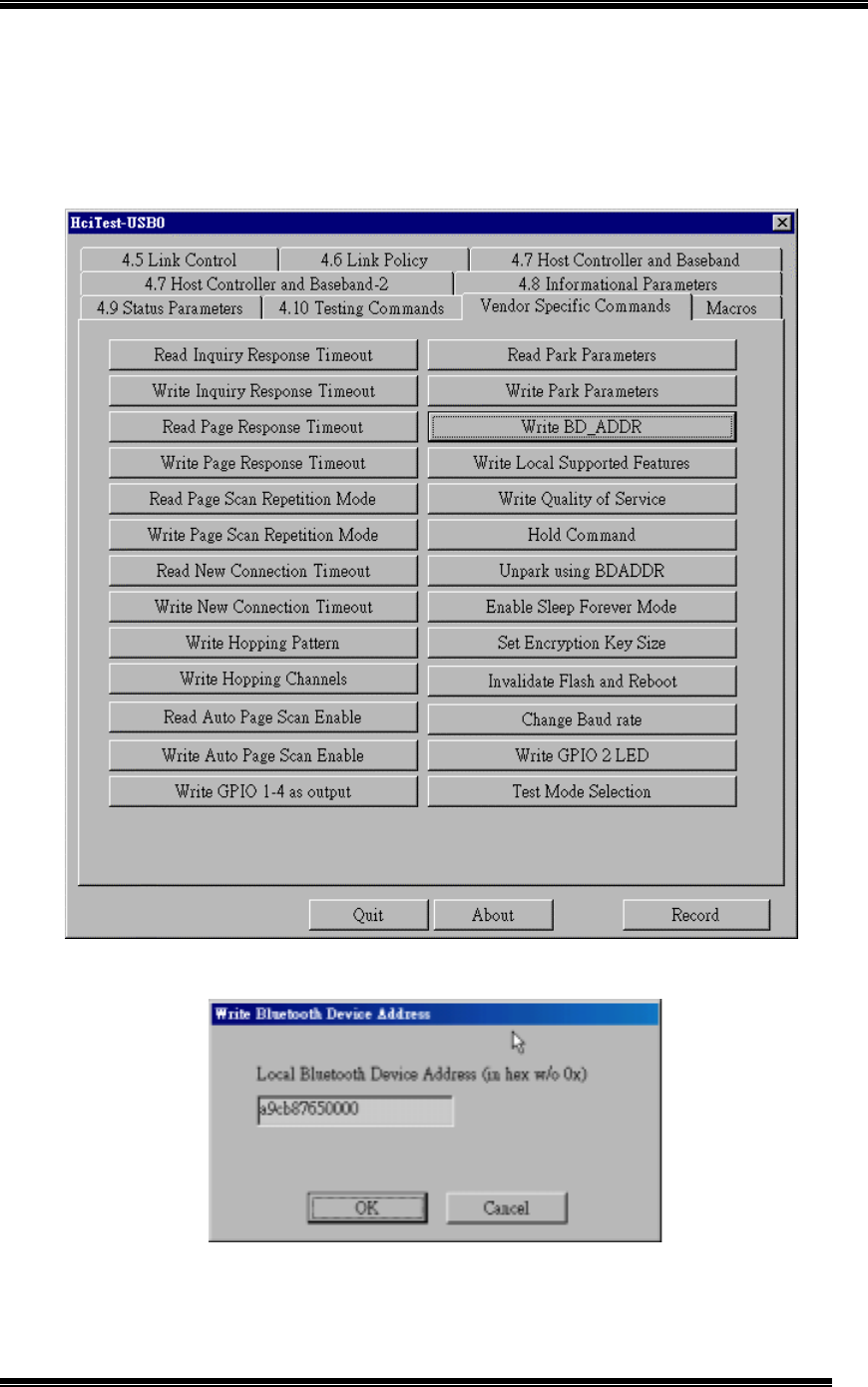
6. On both computers, select “Vender Specific Command” box, then click on the ”Write
BD_ADDR“ button. (as Figure 13). A “Write Bluetooth Device Address” window will
appear on both sides of the PC, please input any 12 hex digits on each side (as Figure
14 (Master), Figure 15 (Slave)). The digits on both sides shall be different.
Figure 13: Write Bluetooth Device Address
Figure 14: Write Bluetooth Device (Master Device) Address
Chapter 5: HCI Testing Procedure
19
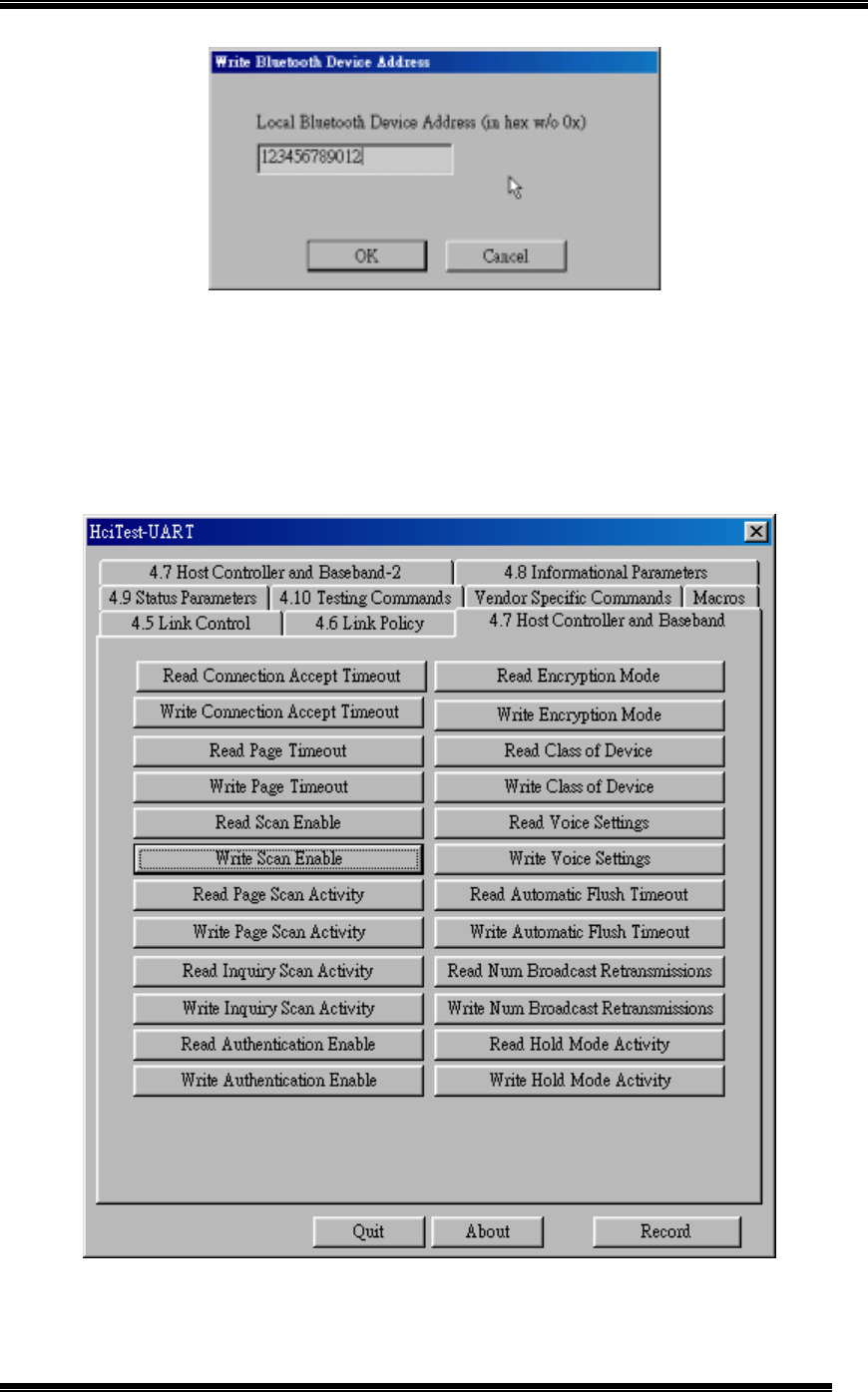
Figure 15: Write Bluetooth Device (Slave Device) Address
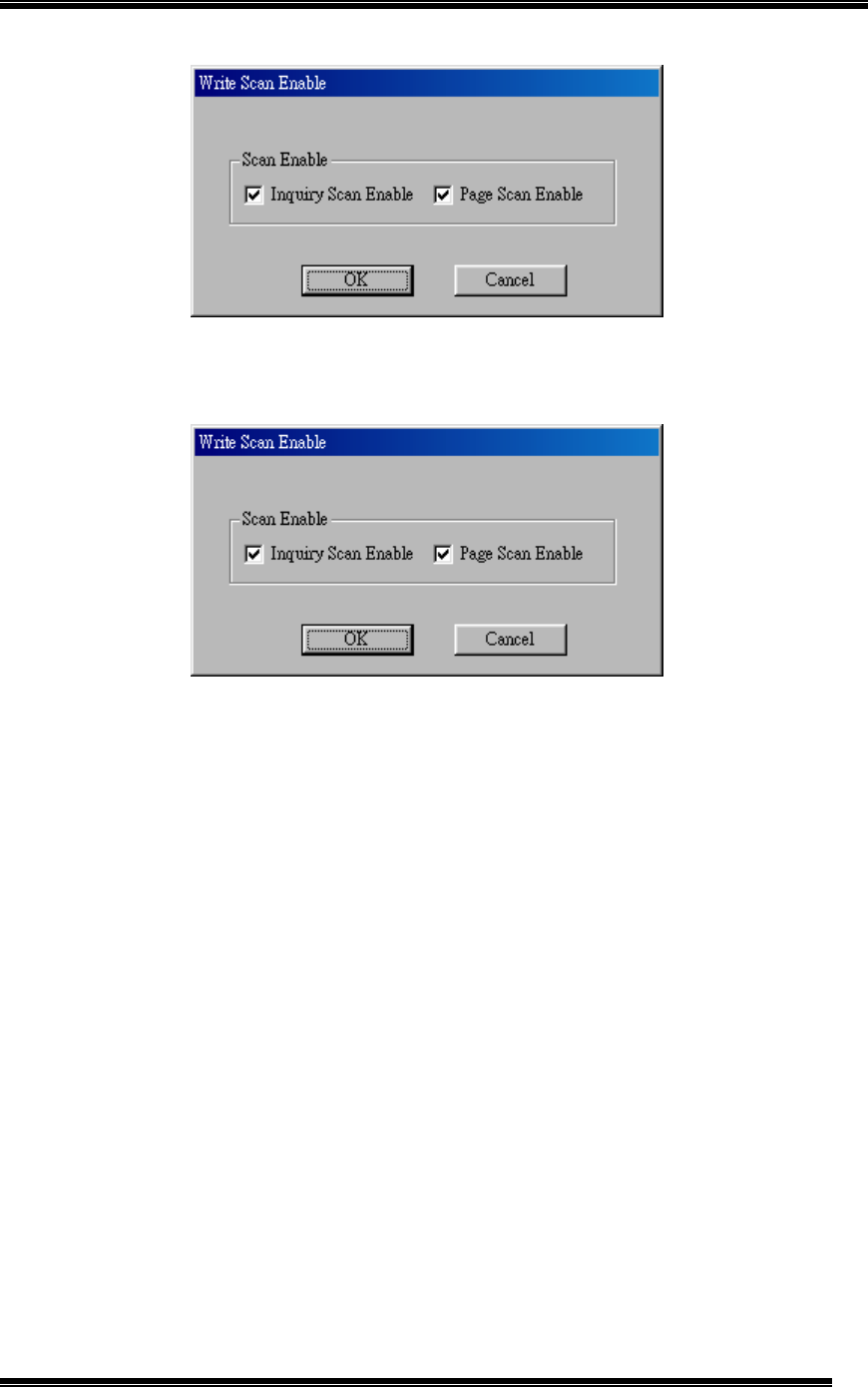
7. On the Slave computer, select “4.7 Host Controller and Baseband” box, then click on
the ”Write Scan Enable” button. (as Figure 16). A “Write Scan Enable” window will
appear (as Figure 17), please deselect Inquiry Scan Enable (as Figure 18).
”
Figure 16: Write Scan Enable
Chapter 5: HCI Testing Procedure
20
Figure 17: Write Scan Enable Window Appear
Figure 18: Deselect Inquiry Scan Enable
Chapter 5: HCI Testing Procedure
21
8. On the Master computer, click on “4.5 Link Control” box, and then click on the ”Create
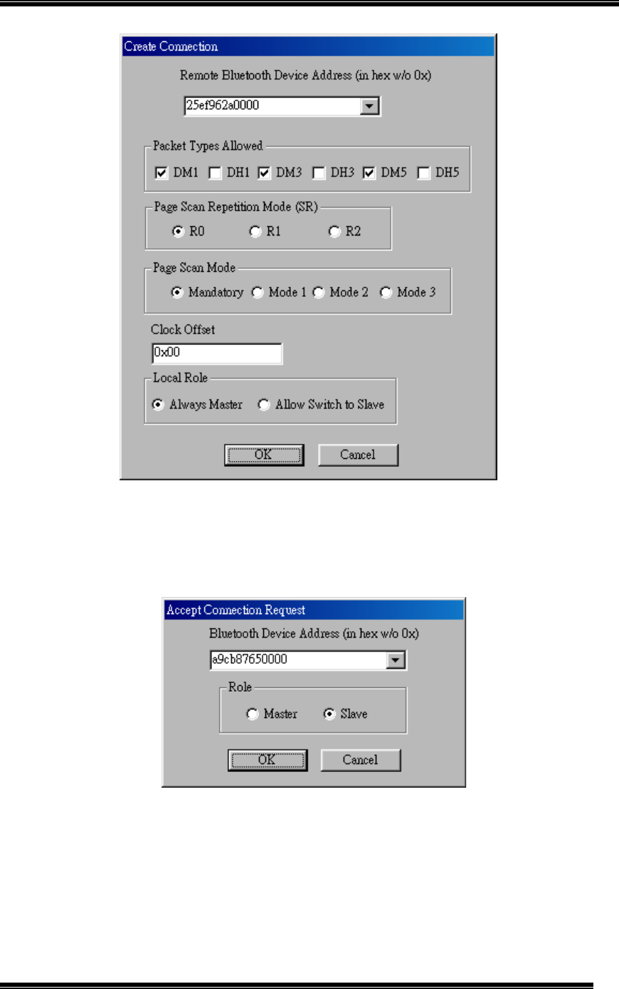
Connection” button. (as Figure 19). A “Create Connection” window will appear, clicks
on OK (as Figure 20).
Figure 19: Create Connection
Chapter 5: HCI Testing Procedure
22
Figure 20: Create Connection
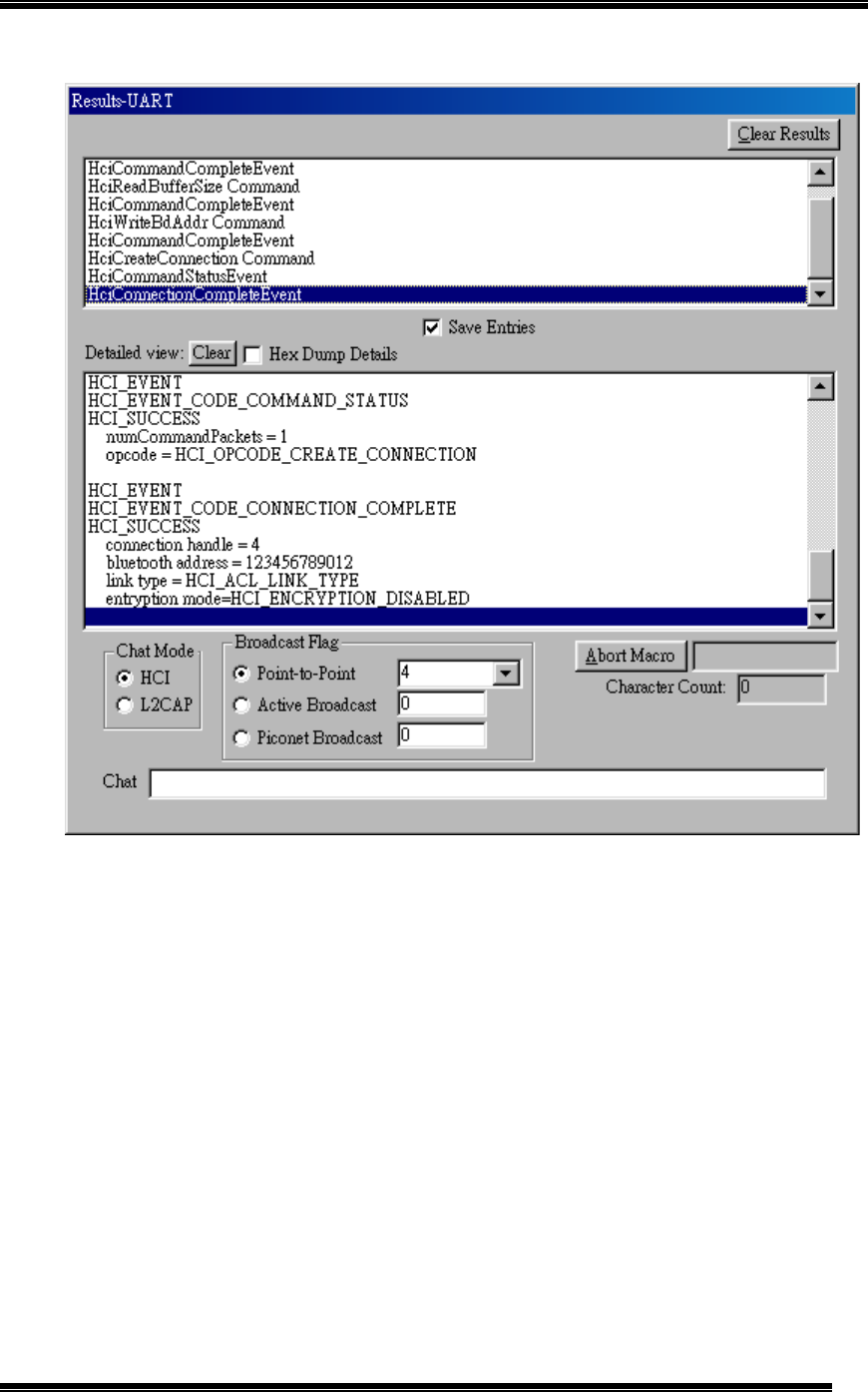
9. On the Slave computer, a “Accept Connection Request” window will appear, click on
the ”Write Scan Enable” button immediately before timeout. (as Figure 21). Please see
the “Result” window for detailed information. (as Figure 22)
Figure 21: Accept Connection Request from Master Device
Chapter 5: HCI Testing Procedure
23
Figure 22: Successful Connection Result on Master Device
Chapter 5: HCI Testing Procedure
24
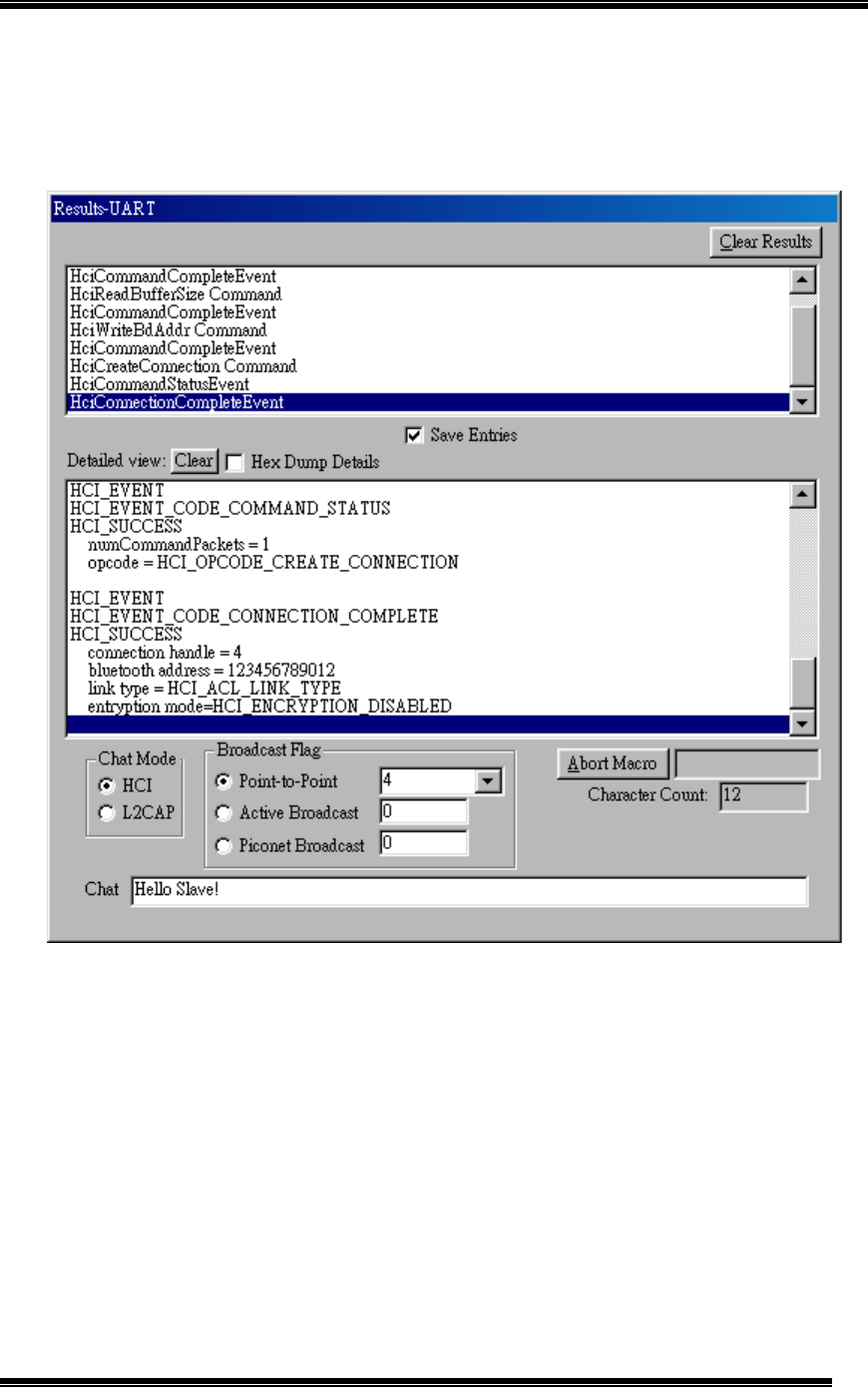
10. On the Master computer, input “Hello Slave!” into “Chat” dialogue box and click “Enter”
button on the keyboard. (as Figure 23).
Figure 23: Type in “Hello Slave!” in Master Device Side
Chapter 5: HCI Testing Procedure
25
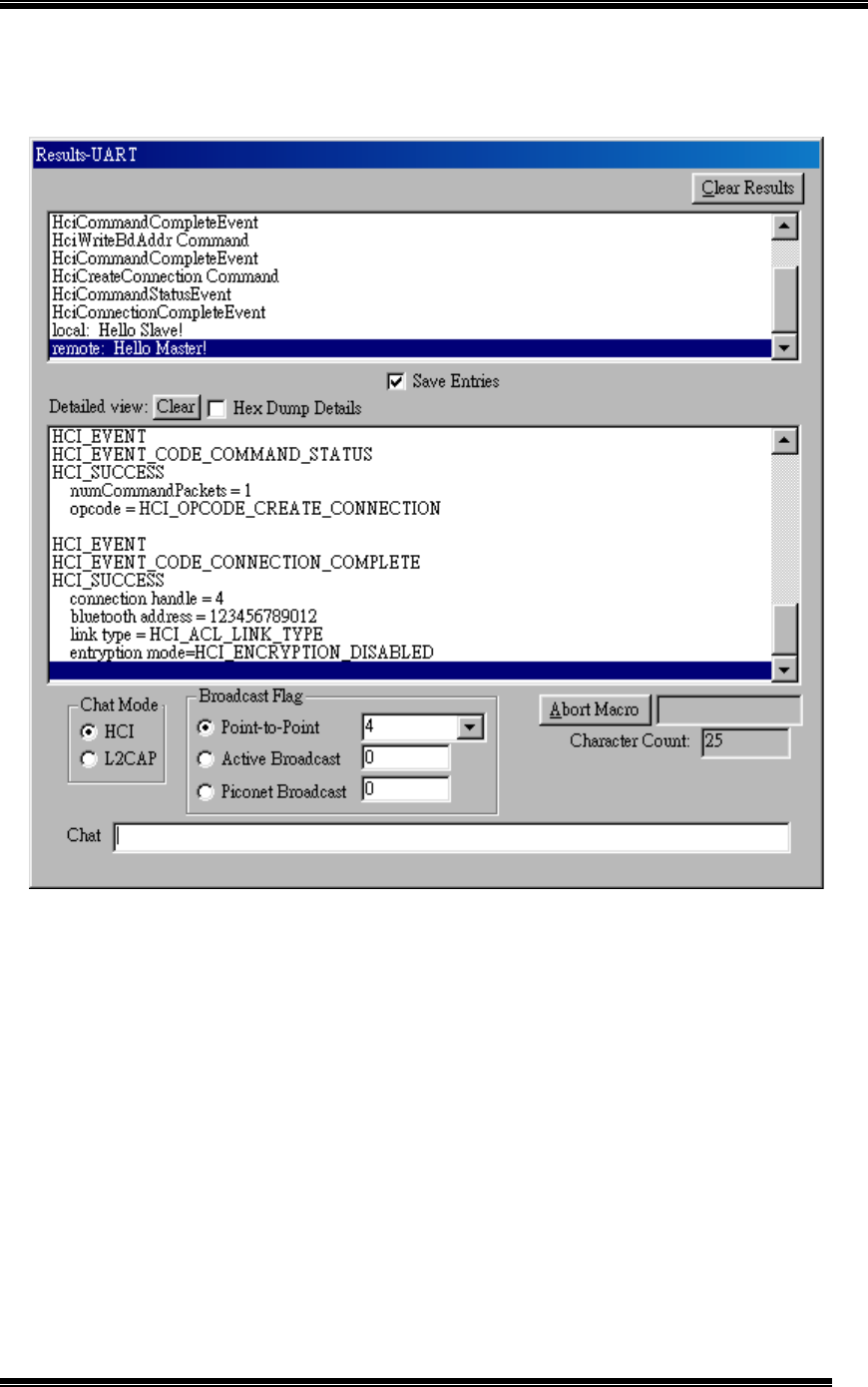
11. On the Slave computer, the screen show “Hello Slave!” message from Master computer.
Then on the Slave side input “Hello Master!” message into “Chat” dialogue box and click
“Enter” button on the keyboard to send the massage back to Master computer. (as
Figure 24).
Figure 24: Receive “Hello Slave!” and Type in “Hello Master!” in Slave Device Side
Chapter 5: HCI Testing Procedure
26
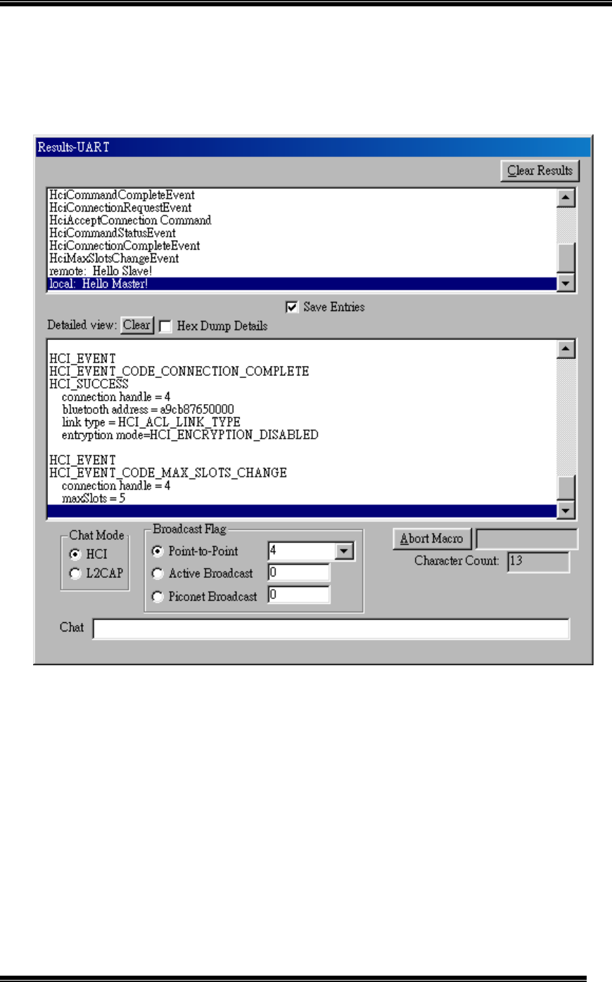
12. On the Slave computer, the screen show “Hello Master!” message from Slave computer..
(as Figure 25).
Figure 25: Receive “Hello Master!” Message from Slave Device
13. For further testing on the data transmission, the user could use Telnet terminal program
to send message or file between these two devices.

Chapter 6: Software Uninstall
27
Chapter 6: Software Uninstall
Remove the TECOM Bluetooth Module BT3010 firmware by performing the following steps.
1. To uninstall the USB test driver, please go to CD-Rom and find “BCBTRMV_1.5.exe” file
inside the directory of “USB Driver”, then click on it to remove the device driver.
2. Once the driver is removed, please find “regedit” program and open it, find the path “ \
HKEY_LOCAL_MACHINE\Enum\USB\VID_0A5C&PID_2033” in the directory of “My
Computer” and delete it.

Chapter 7: Trouble Shooting
28
Chapter 7: Trouble Shooting
1. If there is any problem encountered during installation process:
# Please email to TECOM, sales@ tecom.com.tw