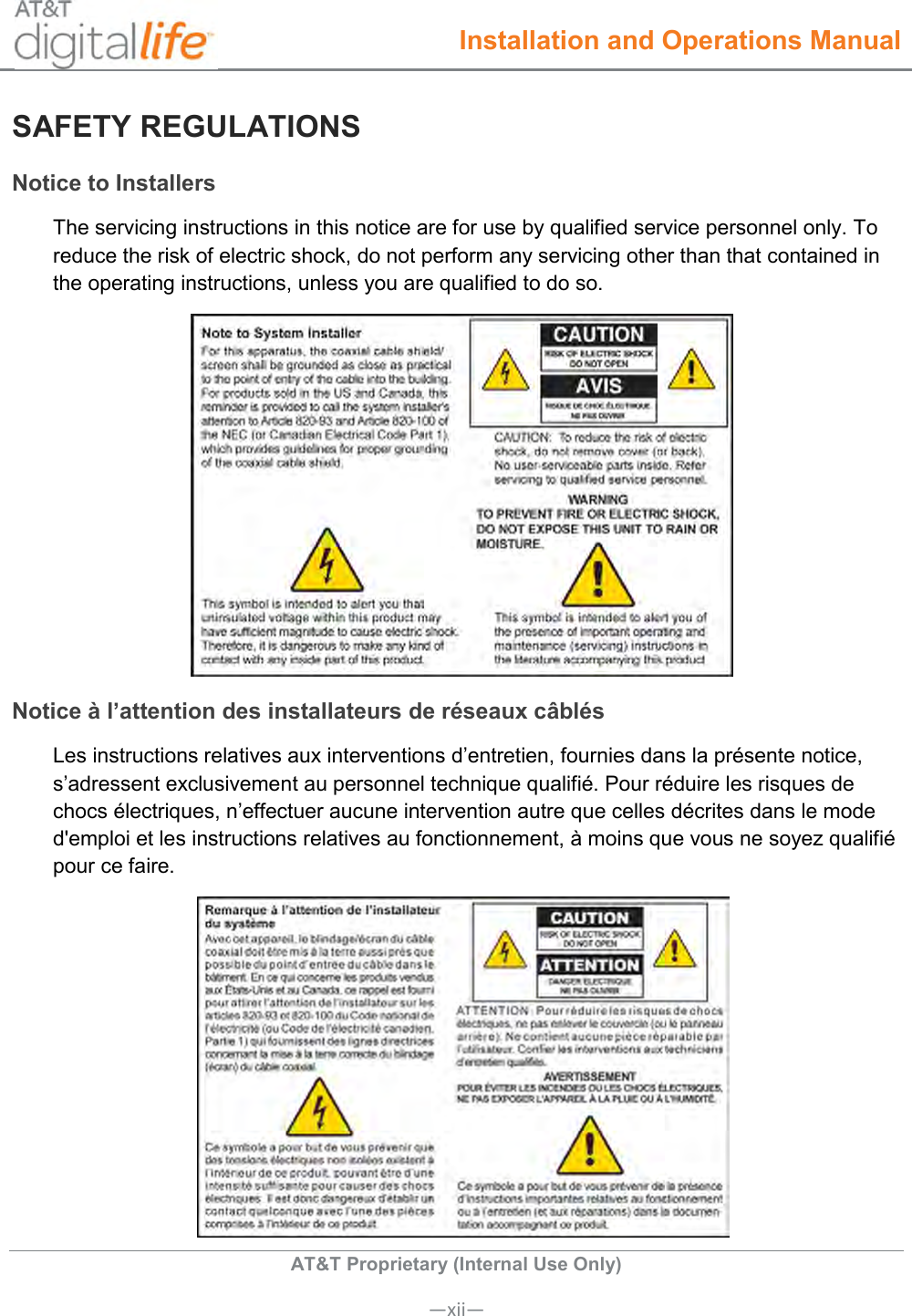
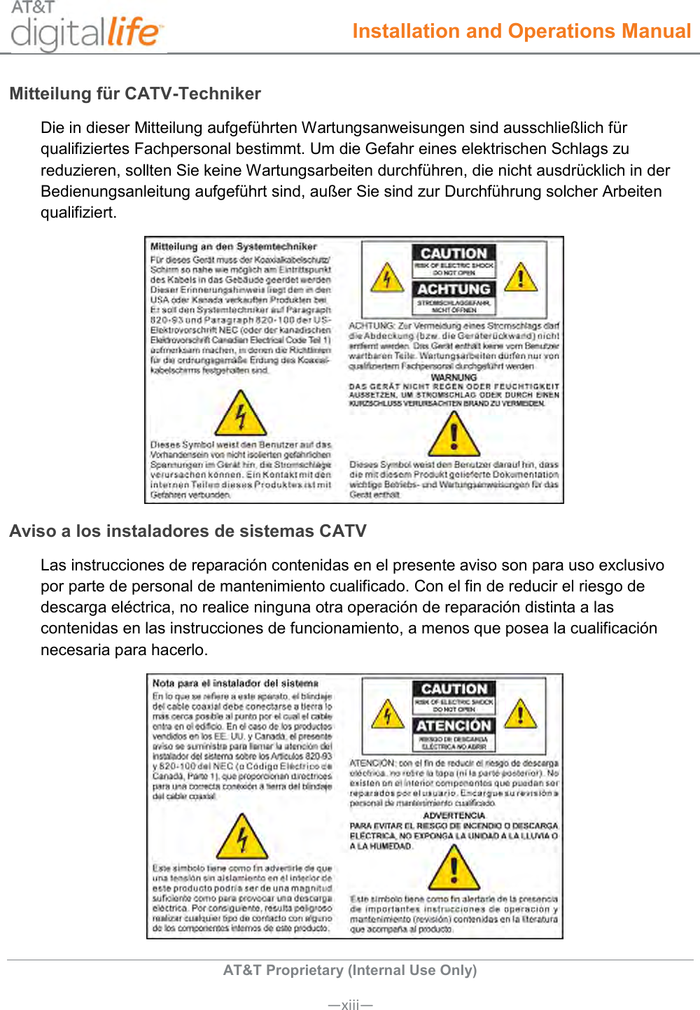
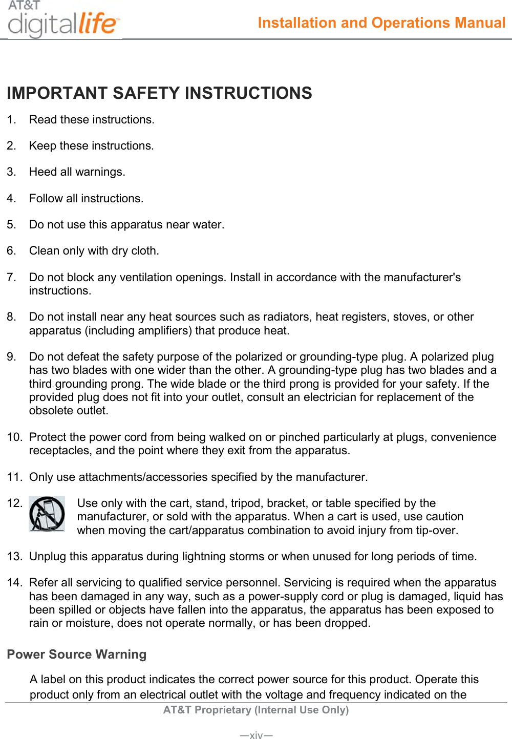
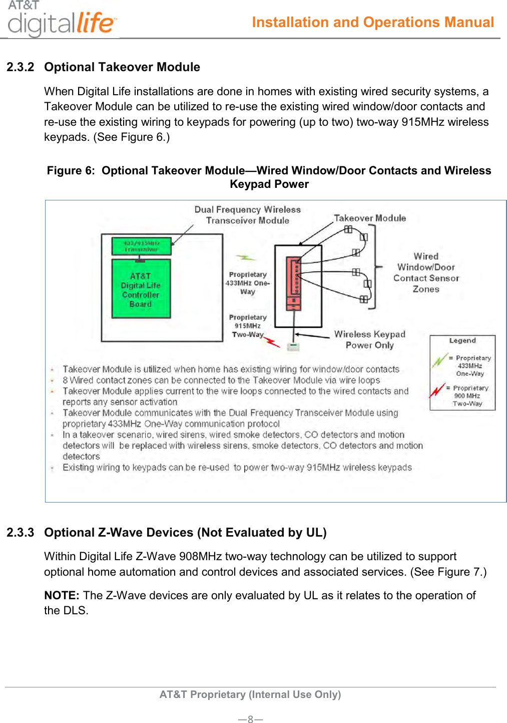
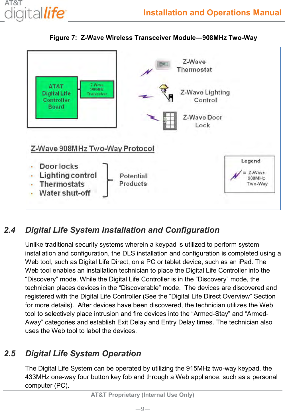
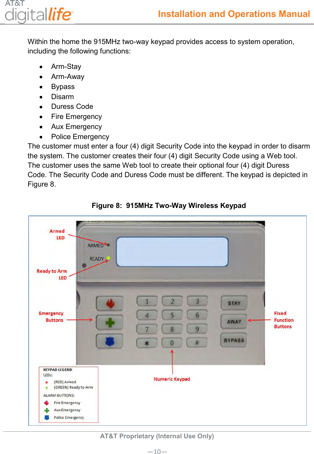
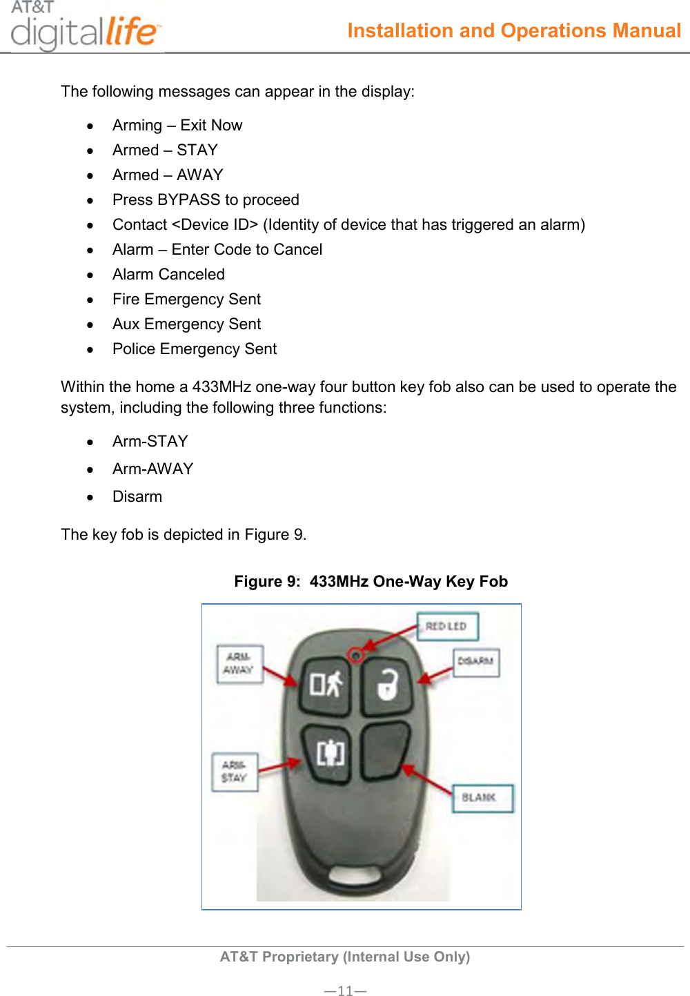
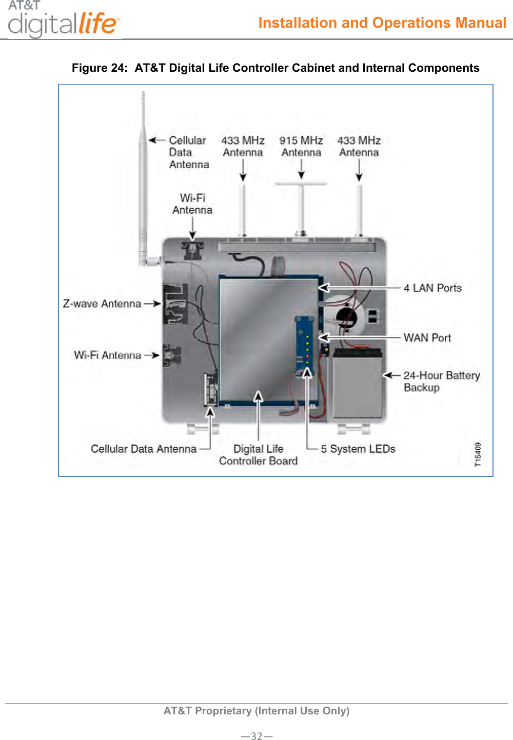
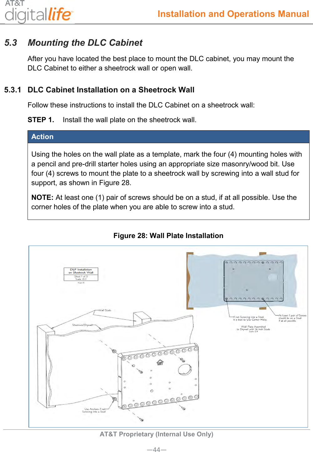
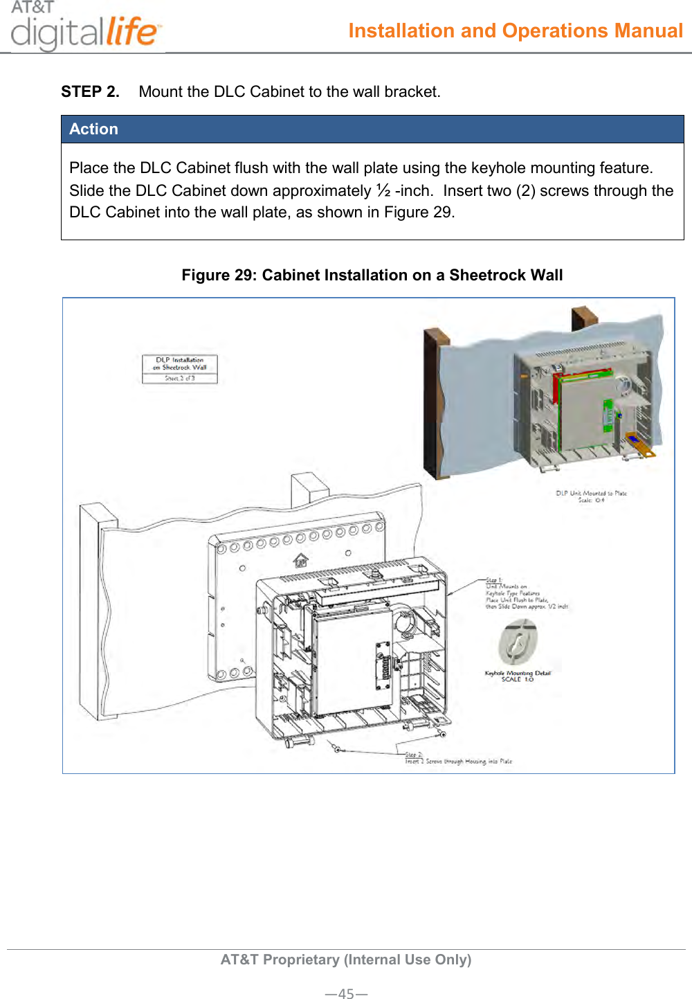
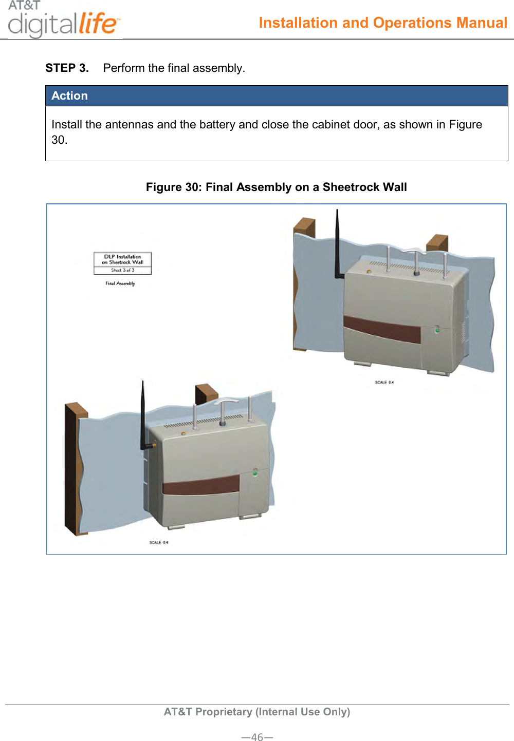
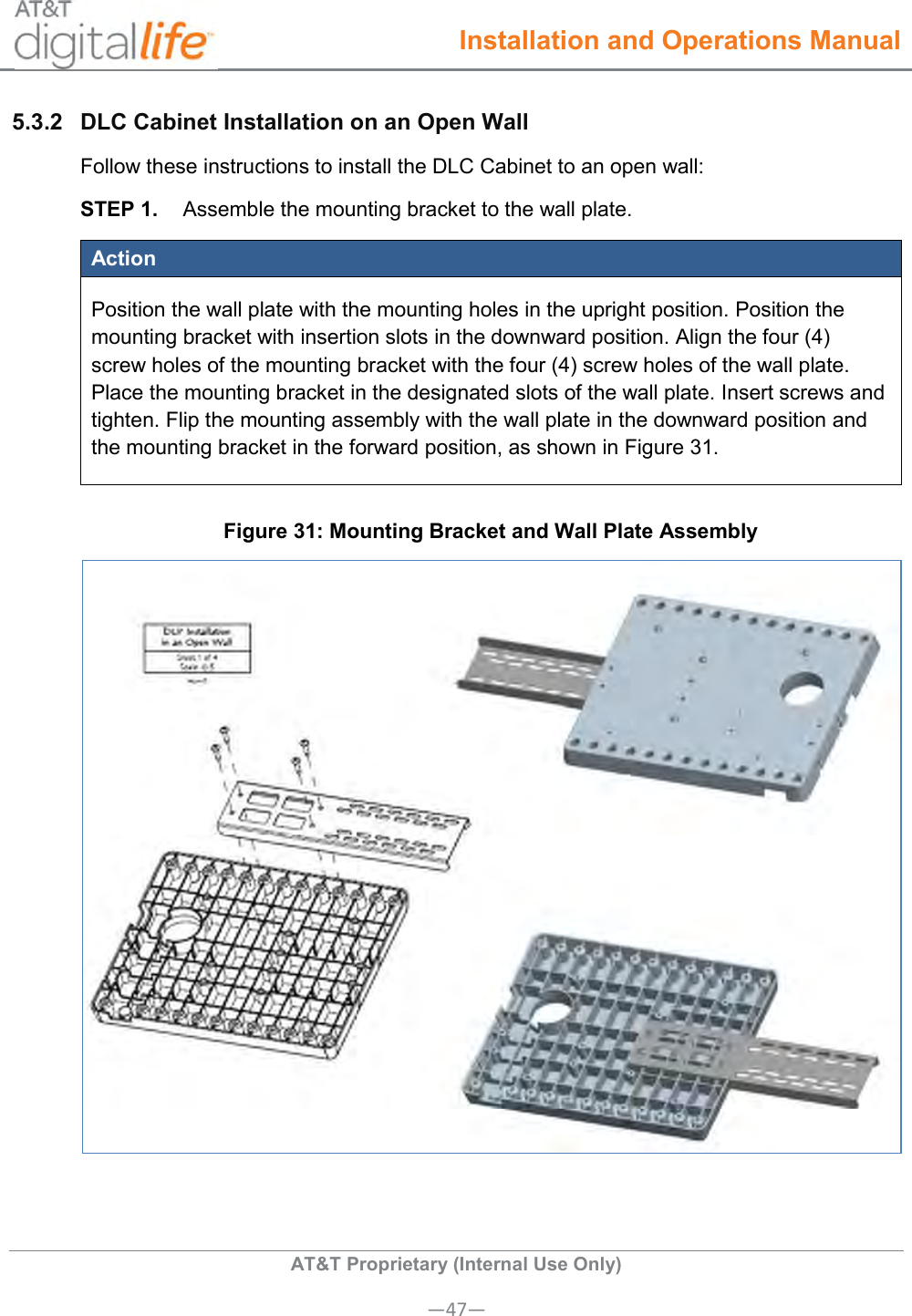
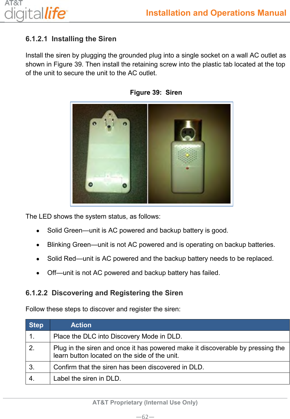
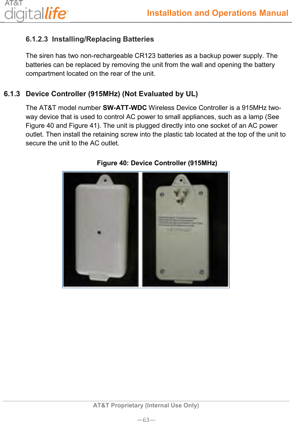
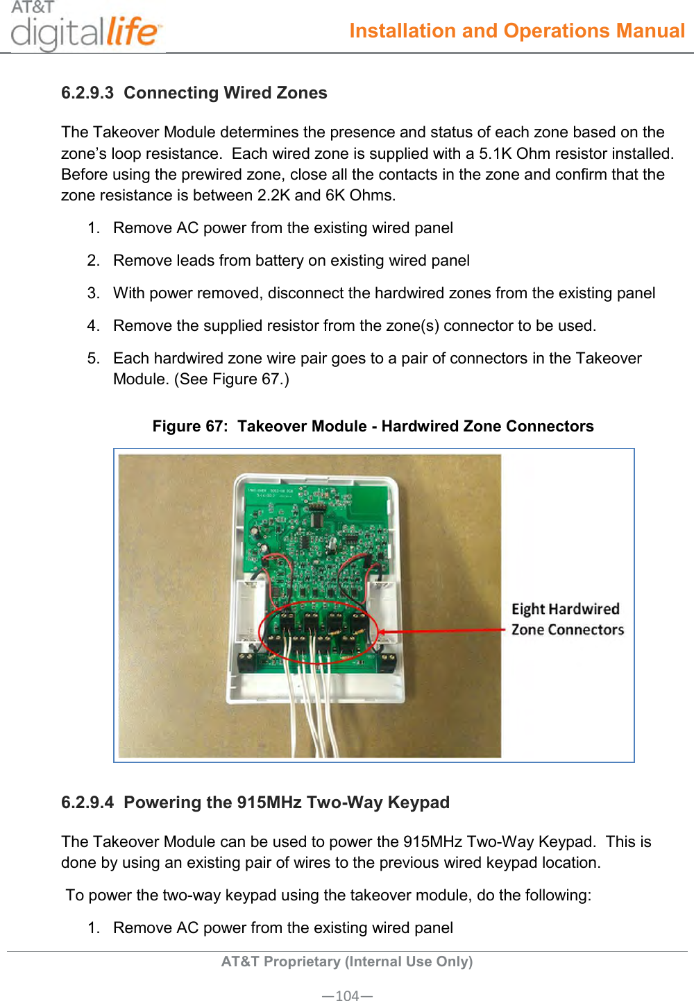
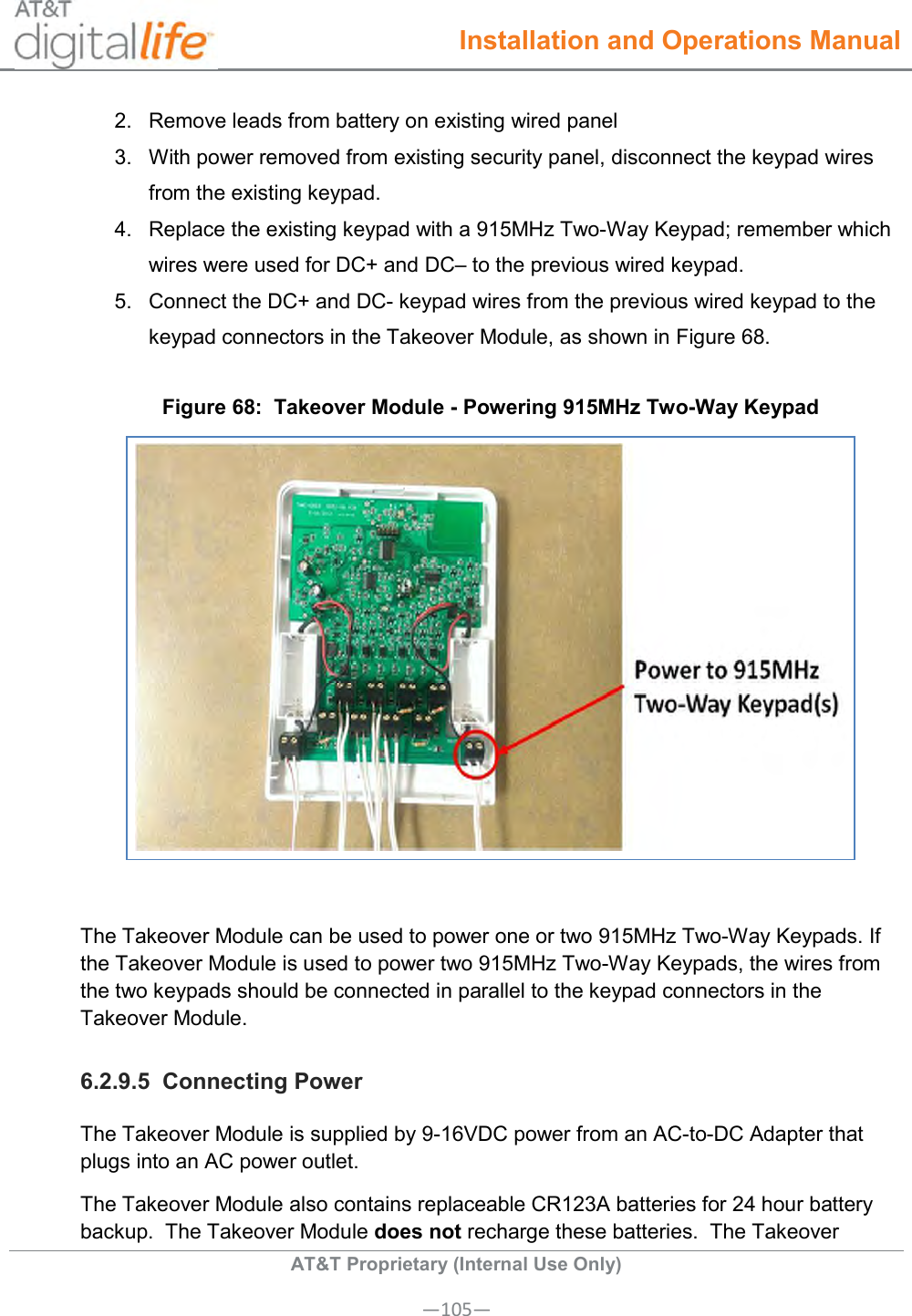
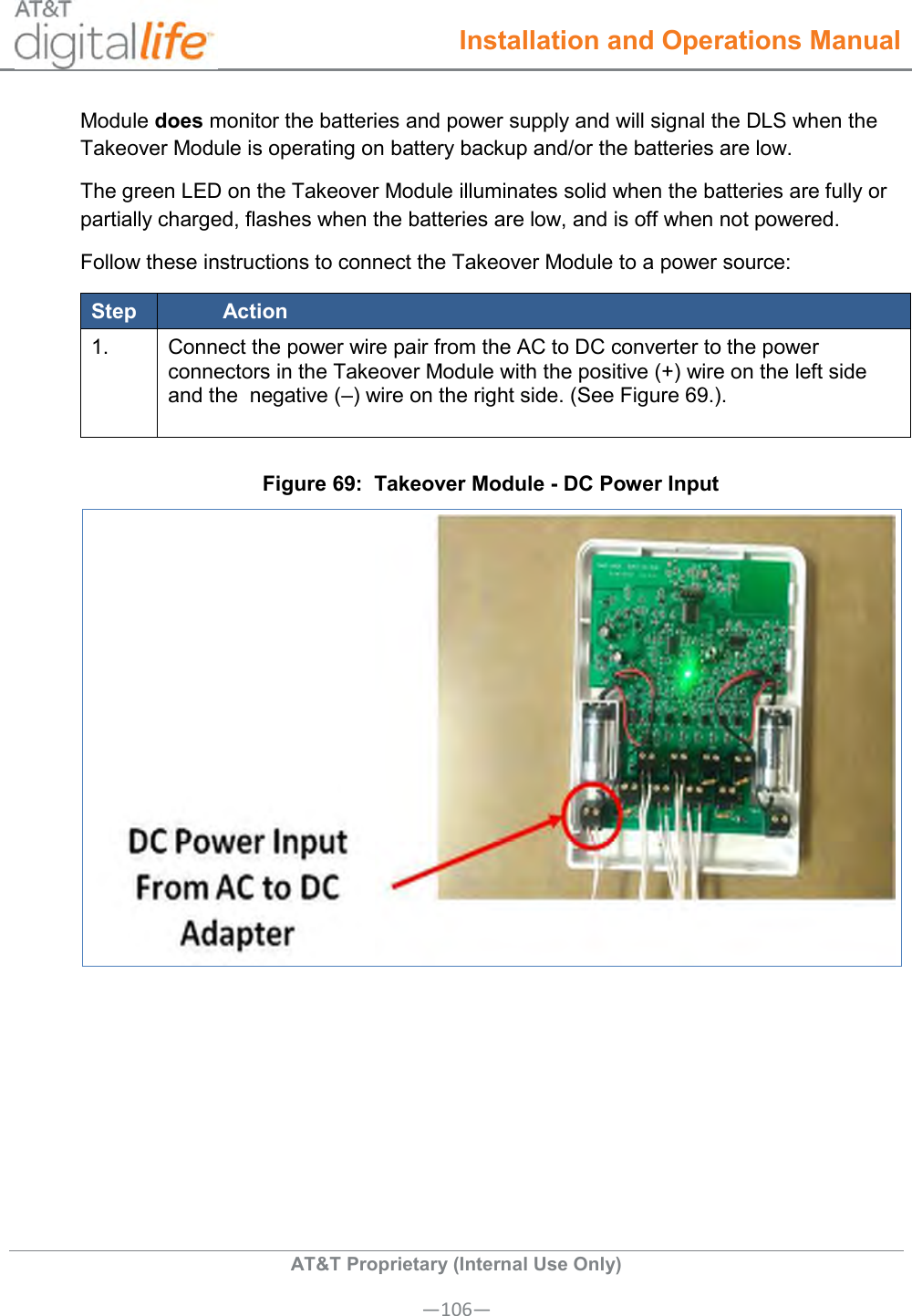
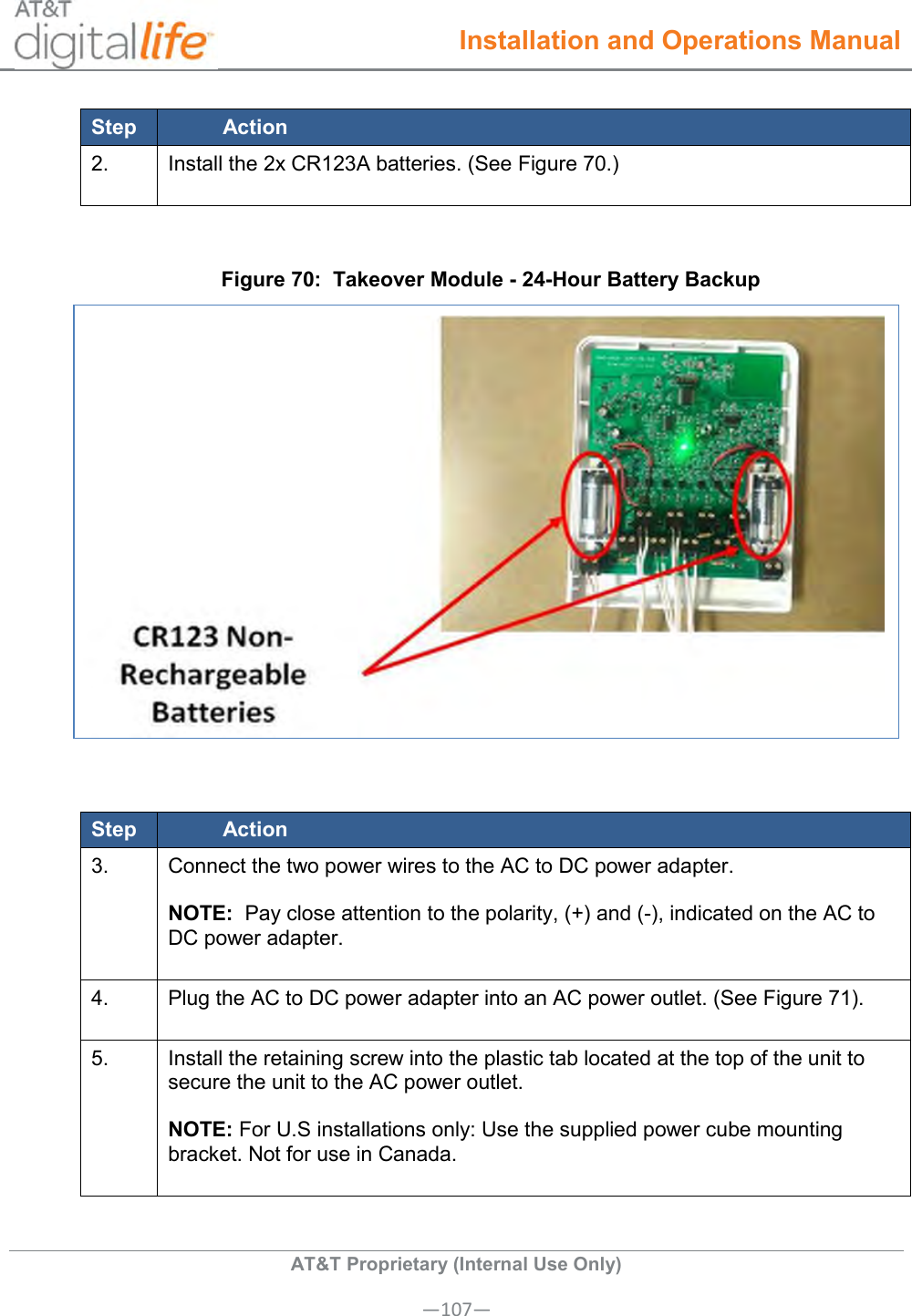
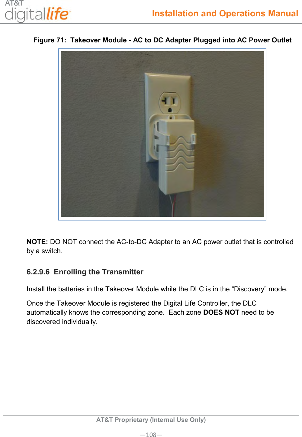
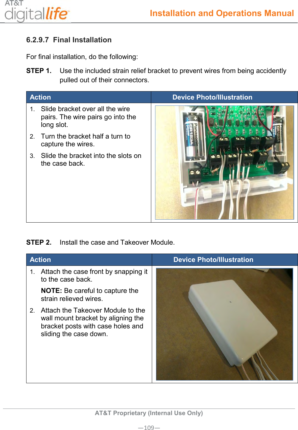
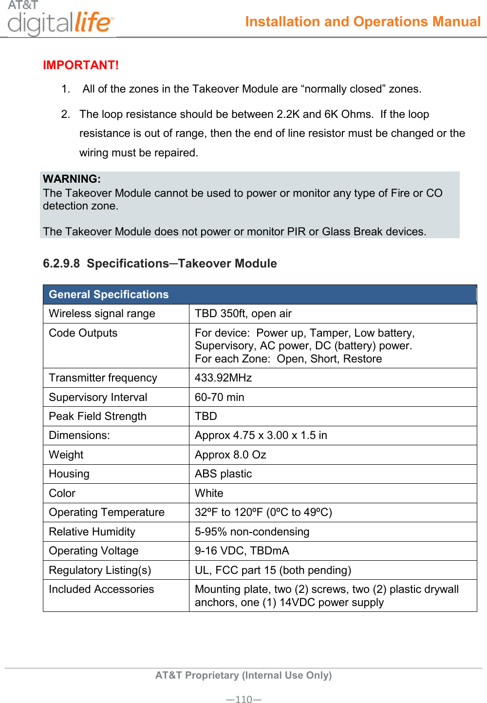
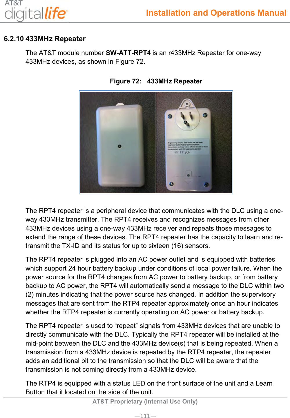
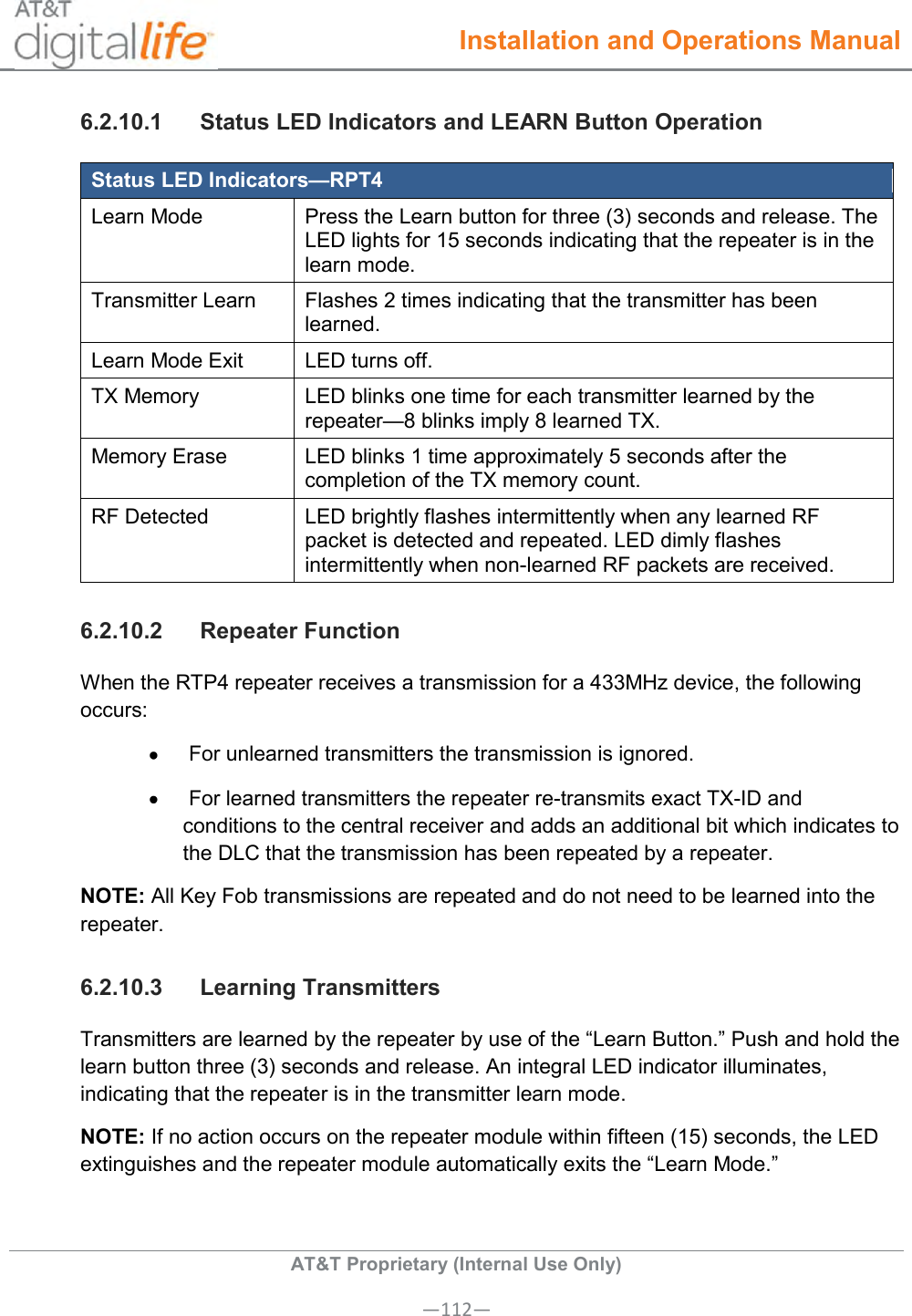
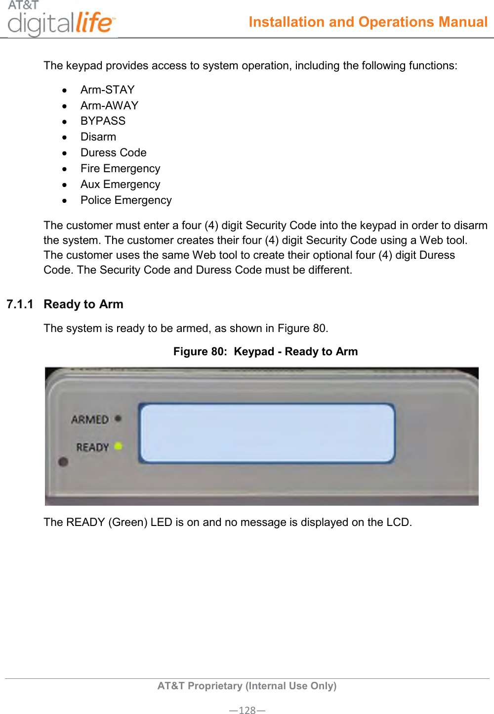
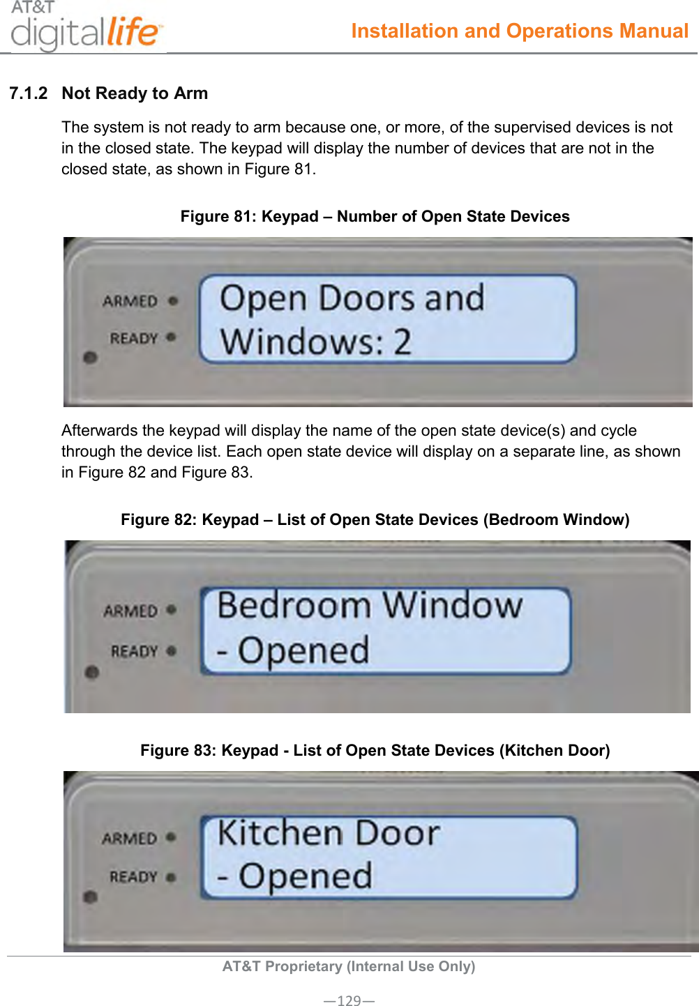
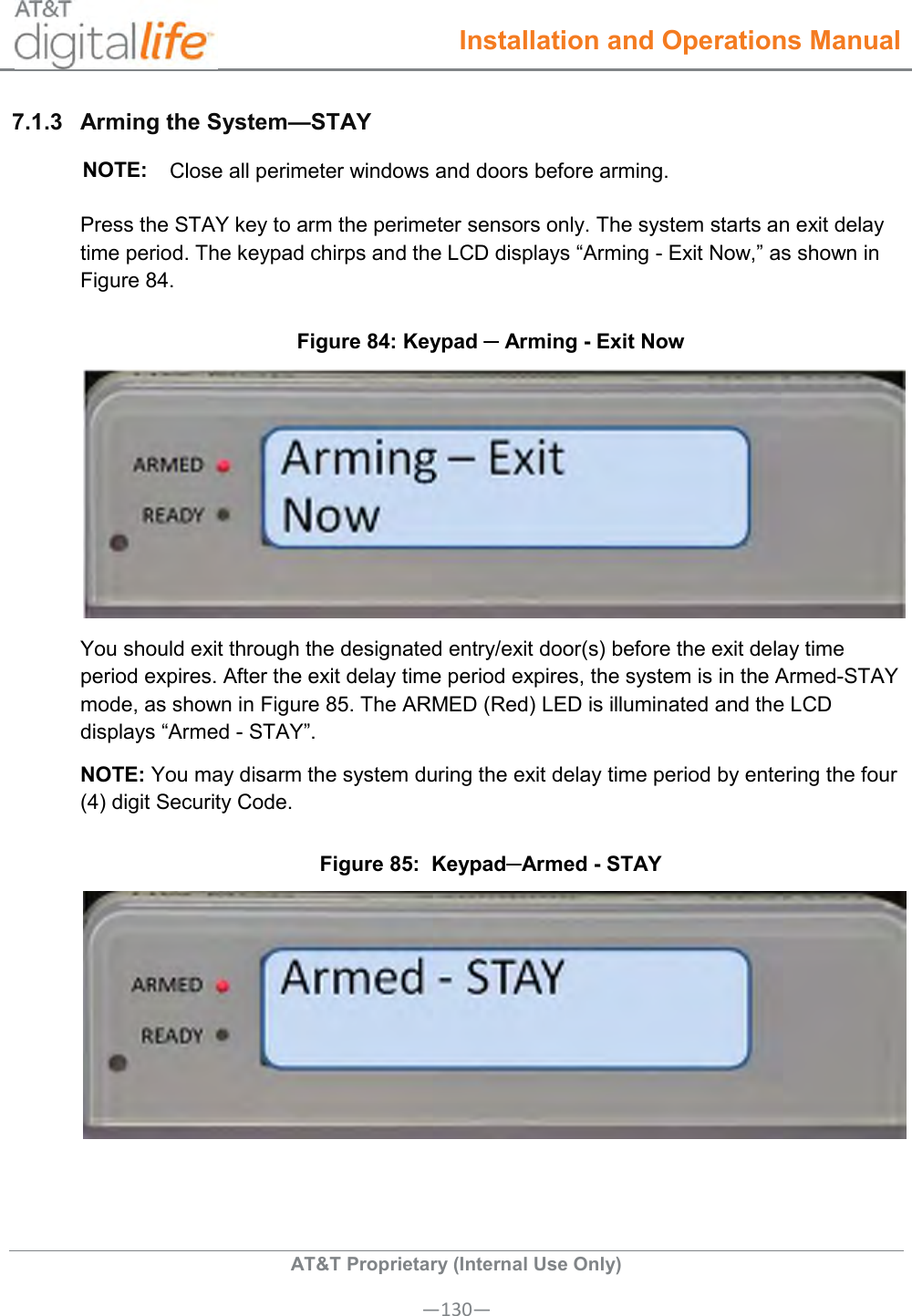
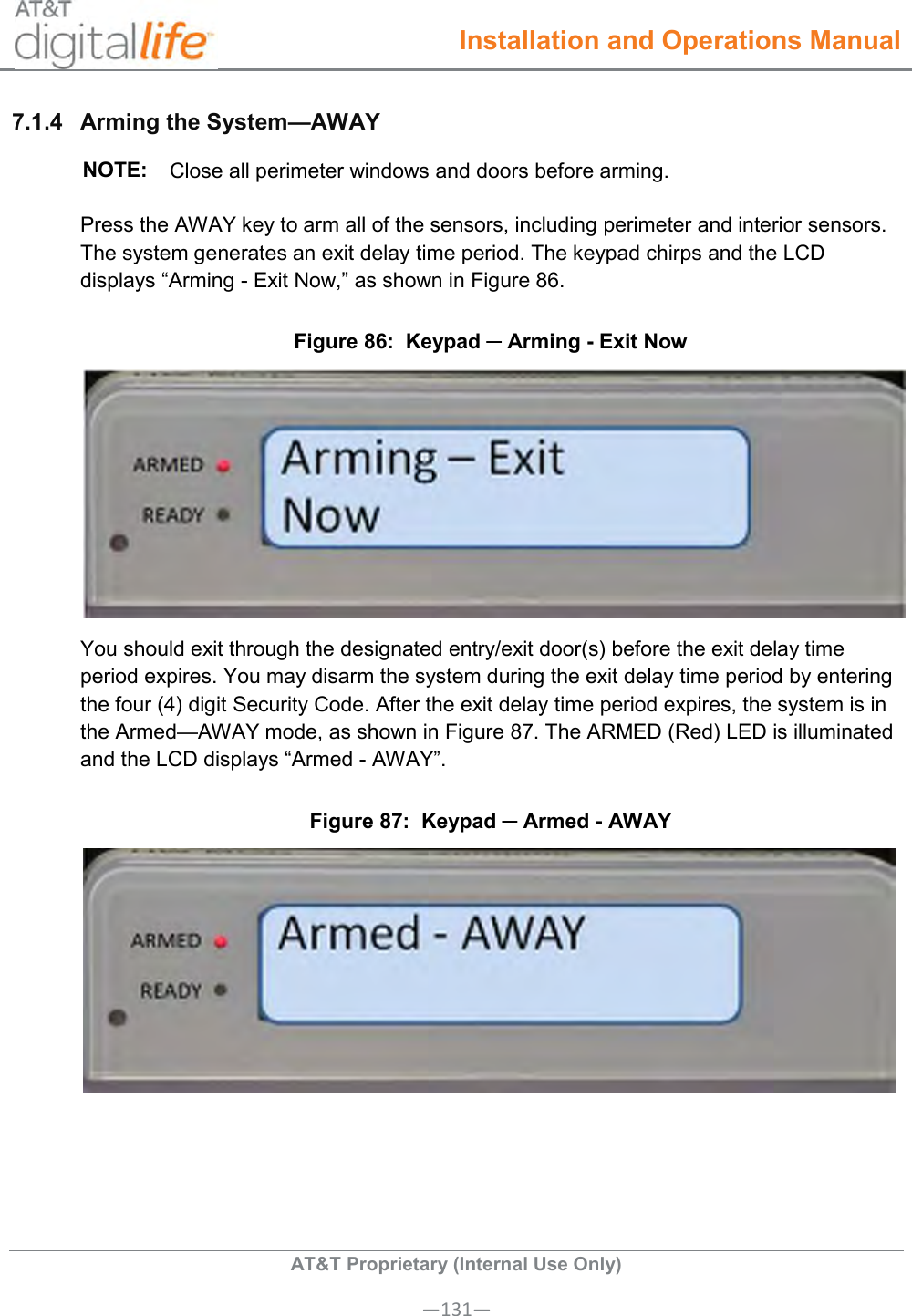
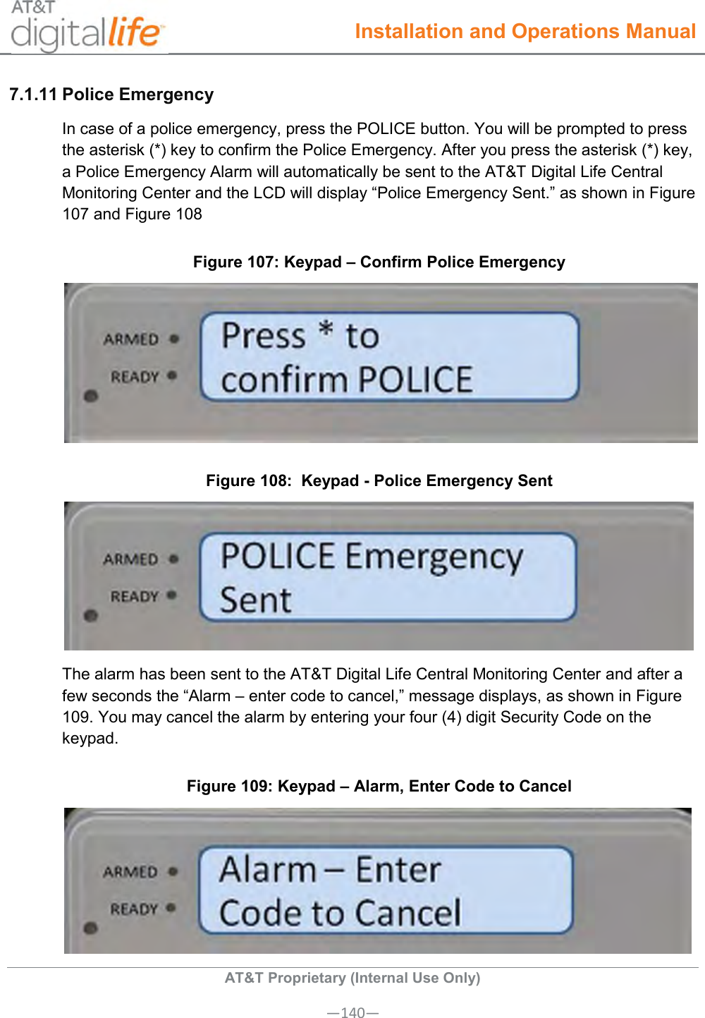
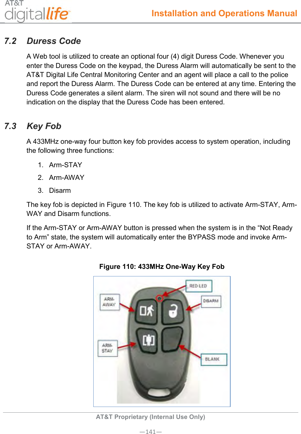
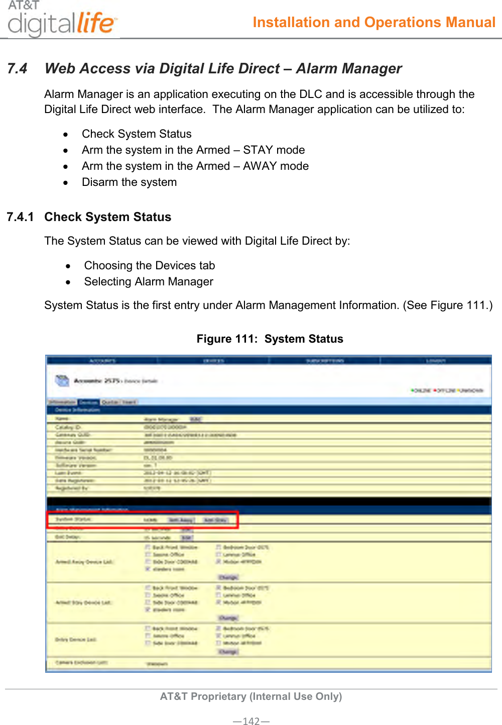
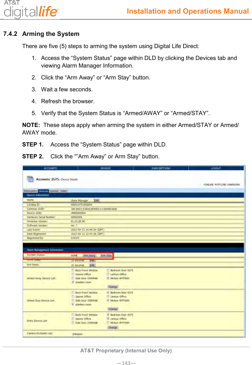
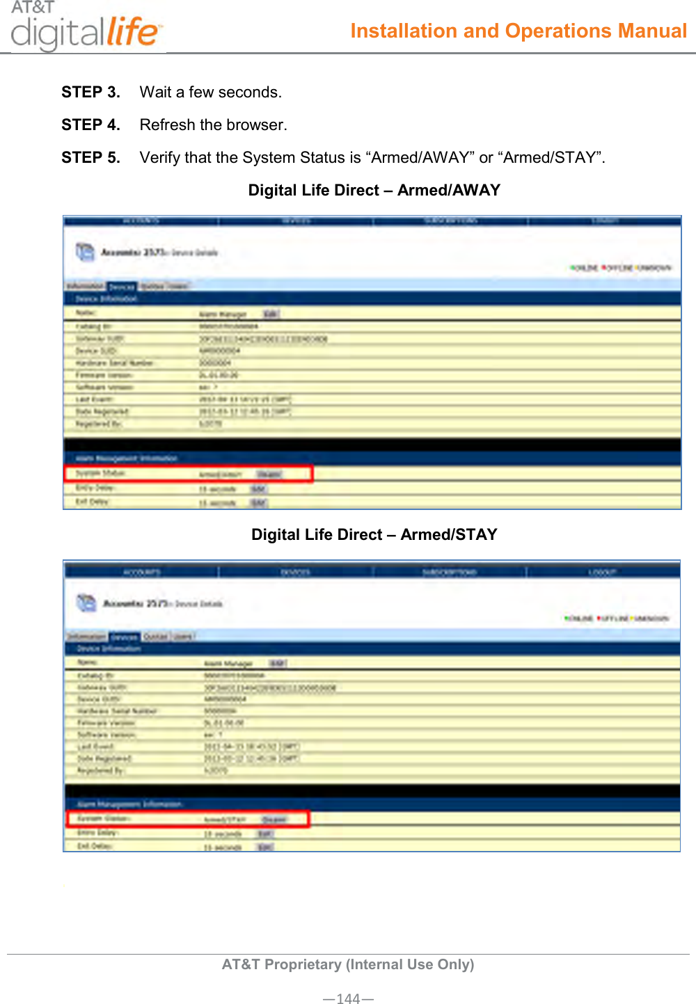
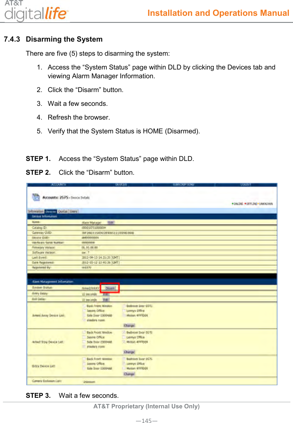
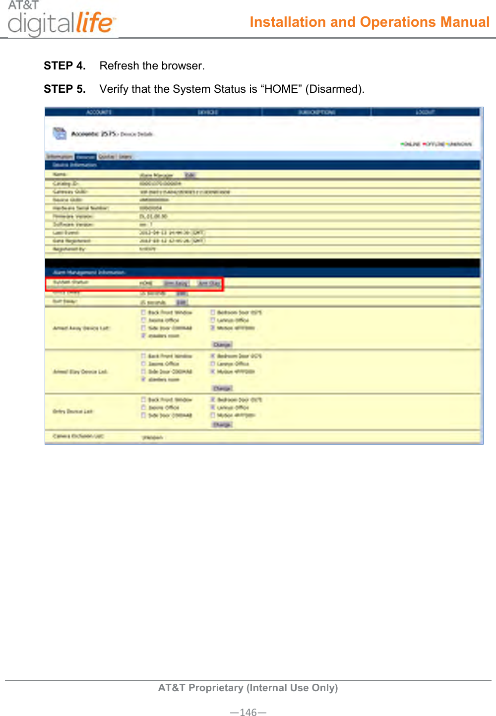
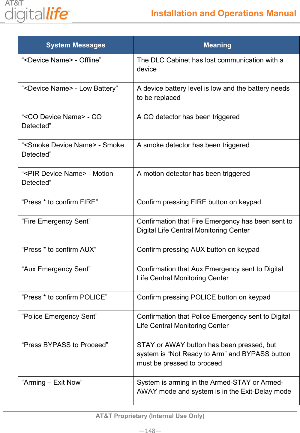
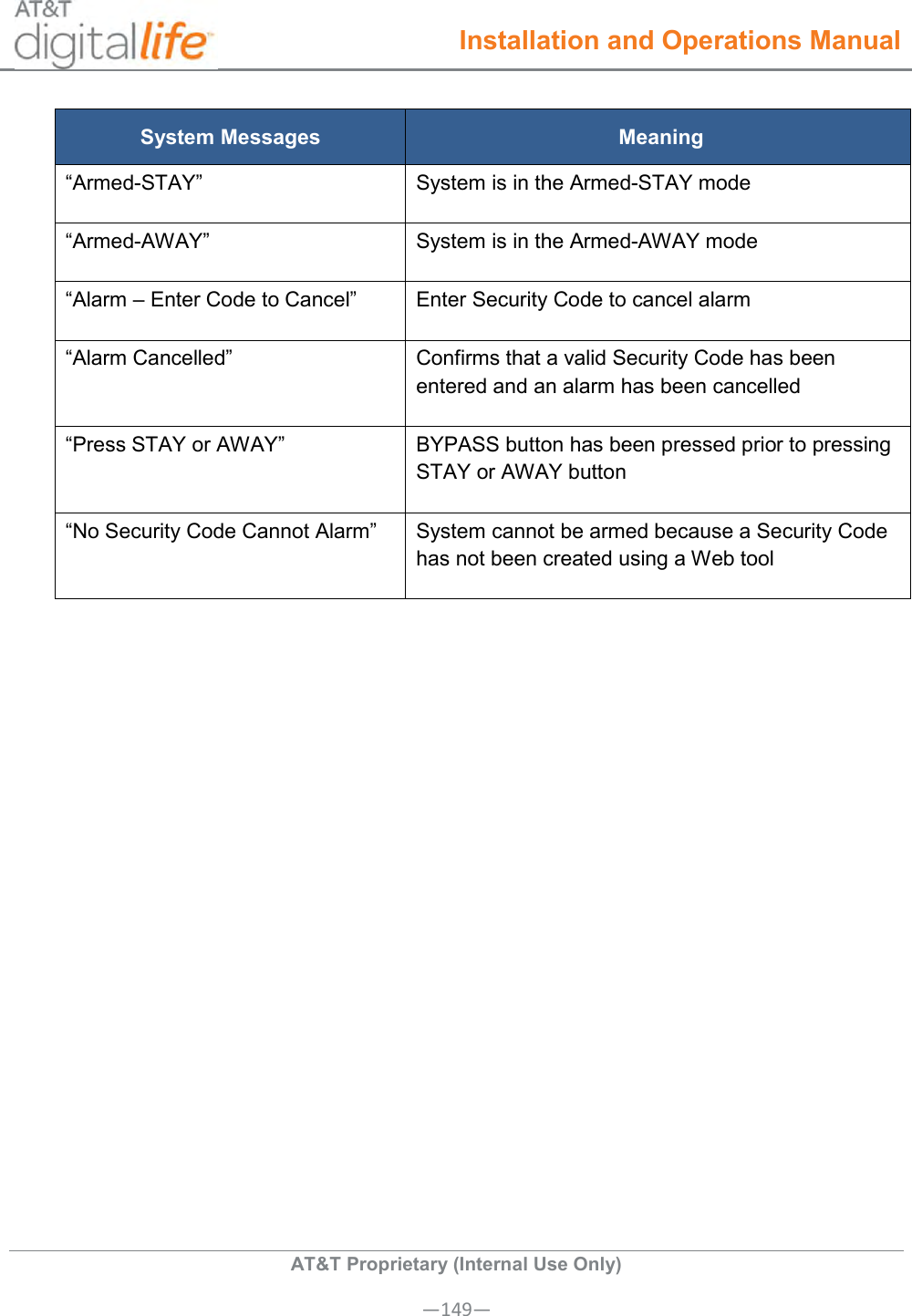
Tecom Co DLC100 HOUSEHOLD BURGLAR-ALARM AND FIRE WARNING SYSTEM UNIT User Manual
Tecom Co Ltd HOUSEHOLD BURGLAR-ALARM AND FIRE WARNING SYSTEM UNIT
UserManual.wiki
>
Tecom Co
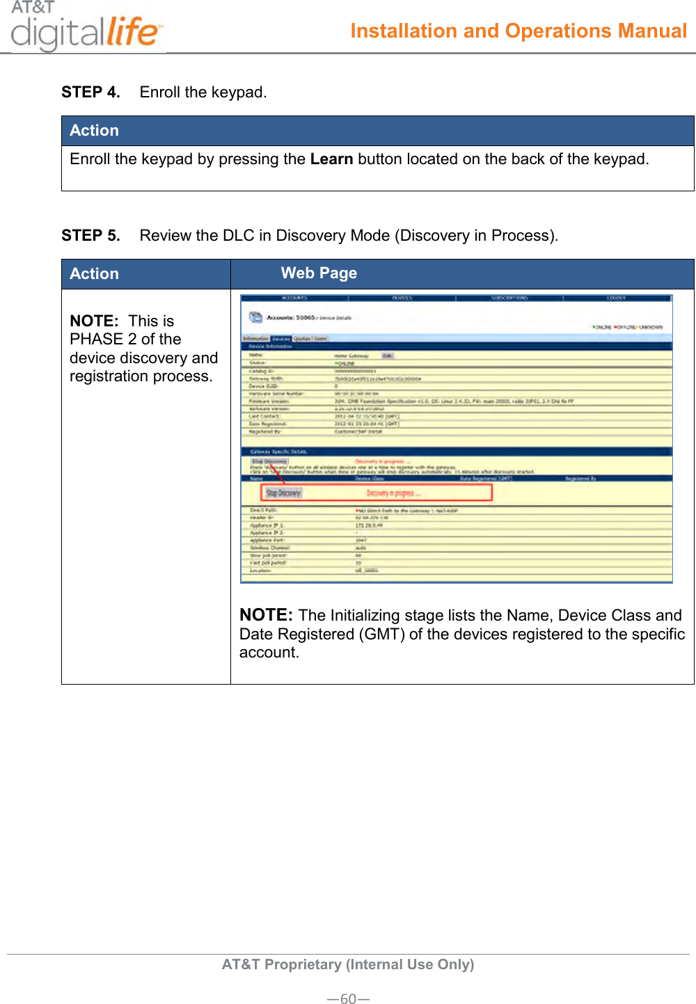
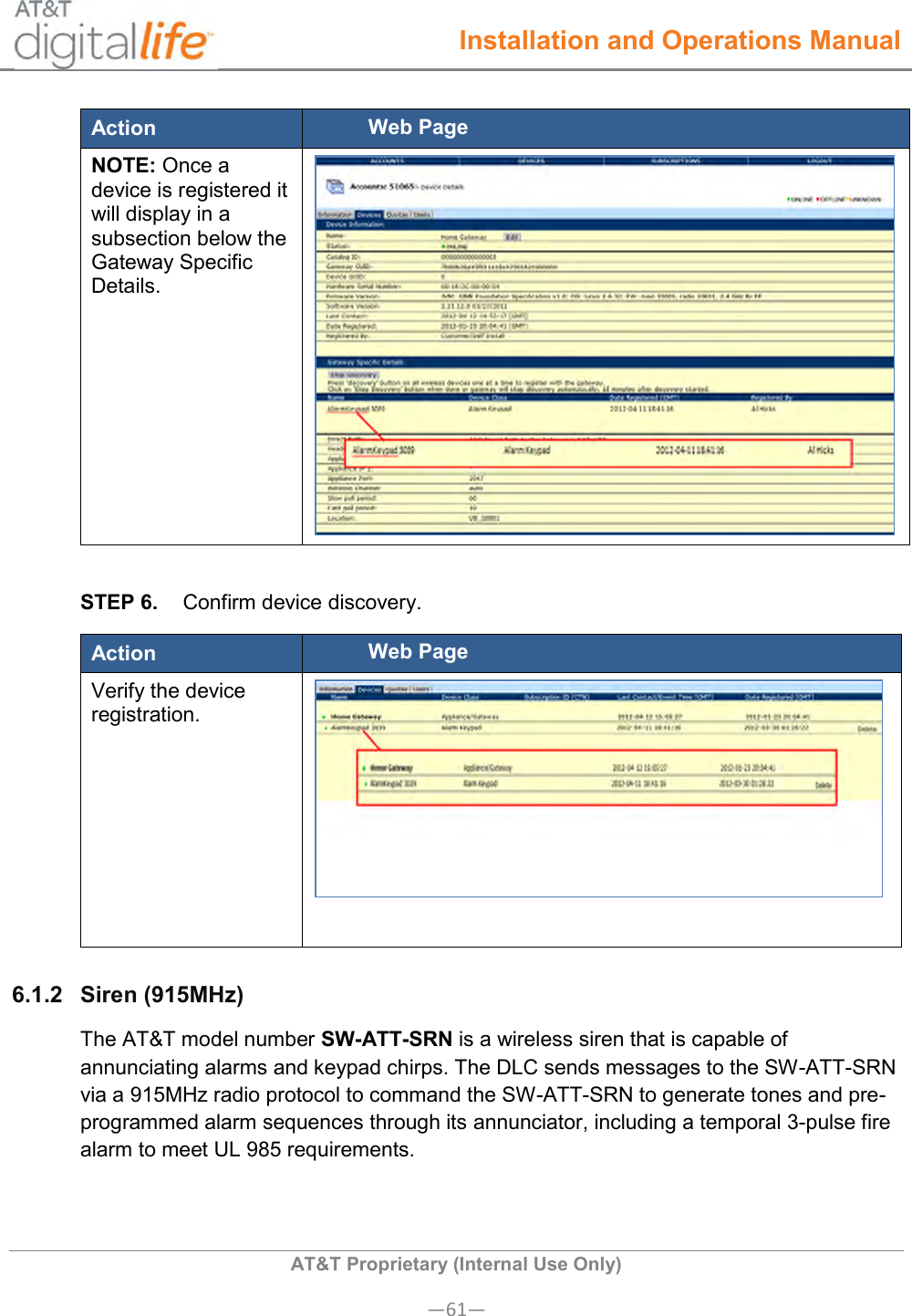
>
DLC100 User Manual
>
User Manual
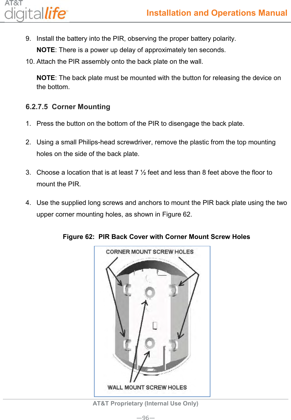
Contents
1.
User Manual
2.
Users Manual
User Manual
Navigation menu
Upload a User Manual
Namespaces
Wiki Guide
HTML
PDF
Info
Views
User Manual
Discussion / Help
Navigation