Tecom Co FC1080 3G FEMTO OUTDOOR AP User Manual FC1080
Tecom Co Ltd 3G FEMTO OUTDOOR AP FC1080
Tecom Co >
Users Manual

FC1080-B1G-US
User Manual

Page: i
Table of Contents
1. INTRODUCTION................................................................................................. 1
2. HARDWARE INSTALLATION............................................................................ 1
3. CONFIGURATION.............................................................................................. 1
3.1. BEFORE CONFIGURATION.......................................................................................... 1
3.2. ESTABLISH THE CONNECTION .................................................................................... 1
3.3. DEVICE INFO............................................................................................................. 2
3.3.1. Summary............................................................................................................. 2
3.3.2. Statistics.............................................................................................................. 2
3.3.3. Route................................................................................................................... 2
3.3.4. ARP..................................................................................................................... 2
3.4. ADVANCED SETUP .................................................................................................... 3
3.4.1. LAN ..................................................................................................................... 3
3.4.2. DNS..................................................................................................................... 3
3.4.3. IPSec................................................................................................................... 4
3.4.4. Certificate ............................................................................................................ 6
3.5. MANAGEMENT........................................................................................................... 8
3.5.1. Backup Settings and Restore Default Settings ................................................... 8
3.5.2. System Log ....................................................................................................... 10
3.5.3. Alarm History..................................................................................................... 10
3.5.4. SNMP Agent...................................................................................................... 11
3.5.5. Internet Time ..................................................................................................... 12
3.5.6. Access Control .................................................................................................. 13
3.5.7. Update Software................................................................................................ 13
3.5.8. Reboot............................................................................................................... 13
4. APPENDIX - TECOM MIB FILE ....................................................................... 15

Page: ii
Revision Information
Revision # Description Date Author
V 0.01 First release. April 08, 2014 Chris Han

Page 1
1. Introduction
The FC1080-B1G-US , 3G Residential Femto Access Point (FAP) is a standalone
WCDMA Femtocell with up to 8 CS/ PS simultaneous users. It’s designed to allow
users to receive better mobile service coverage and capacity in the home with IPSec
as secured backhaul through any broadband internet connection to a mobile service
provider.
Carrier board of FC1080-B1G-US is used to monitor and remote control the
Femtocell. In this document, only carrier board related functions are included. For
more details of FC1080-B1G-US , please refer the other related documents.
Features
IP configuration and DNS
SNMP v1, v2c, v3
IPSec
NTP for time sync
SSH interface for management
Web-based configuration
Remotely intervene to reset, restore default or power cycle the product
Power Supply/Temperature/Case Open monitoring and alarming
Show and manage alarm history
Configuration backup and restore
Firmware upgrade thru web
System Requirements
Along with FC1080-B1G-US , you also need the following equipments or services
before installation.
Computers which equips at least an Ethernet 10Base-T/100Base-T network
interface card (port)
A web browser, such as Microsoft Internet Explorer (V5.0 or later version) or
Firefox, Chrome, which is used to configure the FC1080-B1G-US.

Page 1
2. Hardware Installation
Please refer system installation guide
3. Configuration
3.1. Before Configuration
Before configuration, you have to connect and power FC1080-B1G-US and PC.
Then connect the Ethernet port of PC to LAN port of FC1080-B1G-US. The default
IP address of FC1080-B1G-US is “192.168.1.1” and the default port number is 80.
3.2. Establish the Connection
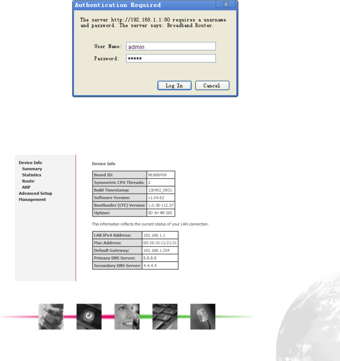
Enter the IP address and Port (default is 192.168.1.1:80) on your web browser. A
dialogue box is popped up and requests to enter the user name and password.
(Figure 3-2-1)
Figure 3-2-1. Authentication
Please use the default user name and password, “admin” and “admin”, and click OK
button to login into the system.
Once authentication process is verified, the home page “Device Info - Summary” is
shown on your browser. (Figure 3-2-2)
Figure 3-2-2. Device Info Page
Page 1
In “Device Info” page, it shows you the basic information about the equipment, such
as software version, MAC address, LAN IP and DNS.
3.3. Device Info
3.3.1. Summary
This page is already introduced in section 3.2.
3.3.2. Statistics
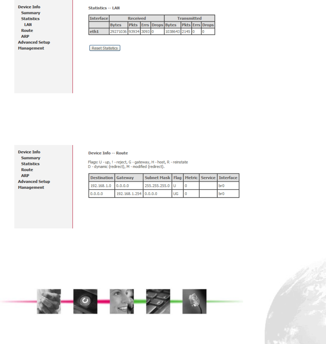
In this page (Figure 3-3-1) you can get the network statistics of the LAN. Click “Reset
Statistics” to clean up all network statistics.
Figure 3-3-1. Device Info - Statistics
3.3.3. Route
In this page you can get the IP route information of the device. (Figure 3-3-2)
Figure 3-3-2. Device Info - Route
3.3.4. ARP
This page shows an ARP table which maps IP network addresses to hardware
addresses used by data link level protocol. (Figure 3-3-3)
Page 2
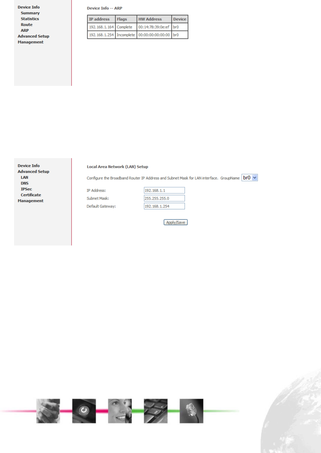
Figure 3-3-3. Device Info - ARP
3.4. Advanced Setup
3.4.1. LAN
Click the “Advanced Setup/LAN” button on the left hand side to enter into the
configuration of LAN.(Figure 3-4-1)
Figure 3-4-1. Advanced Setup - LAN
In this page, you may program the IP address of LAN, its subnet mask and the
default gateway.
Before you leave, please click “Apply/ Save” button to save the changes you made.
3.4.2. DNS
Click the “Advanced Setup/DNS” button on the left hand side of the web page to
enter into the DNS server configuration. (Figure 3-4-2)
Page 3
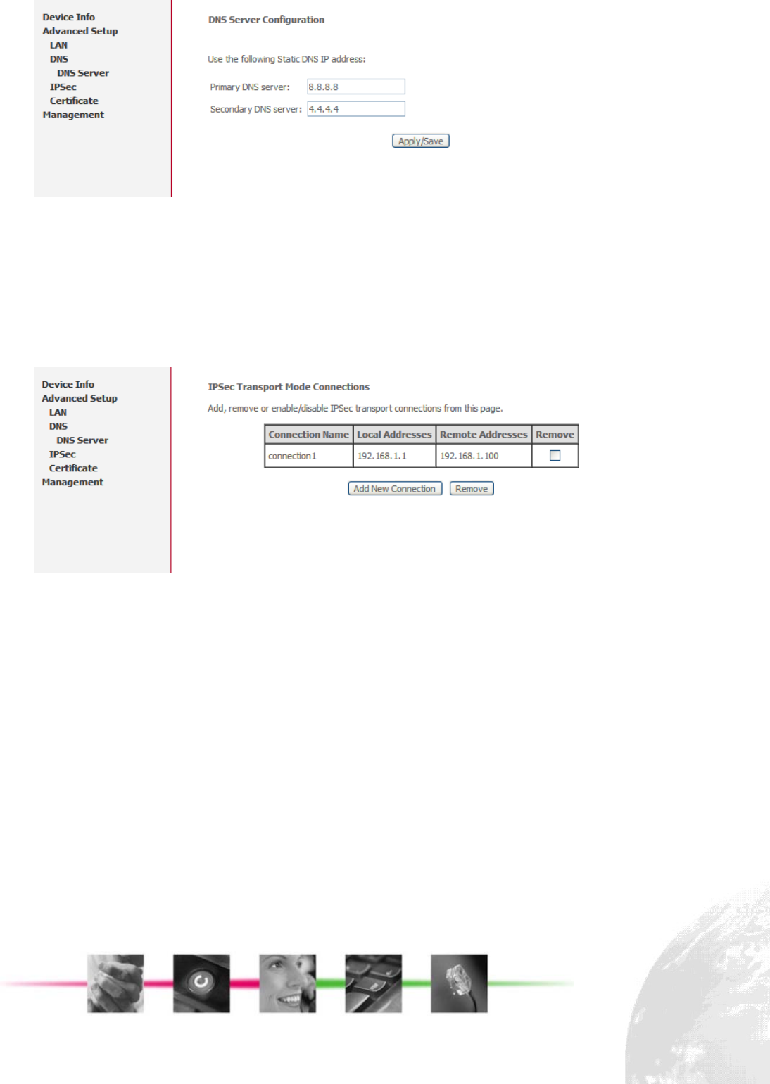
Figure 3-4-2. Advanced Setup – DNS
For the details of DNS servers, please contact your ISP.
3.4.3. IPSec
To use IPSec user interface, choose “IPSec” under “Advanced Setup” menu. The
base screen will be shown: (Figure 3-4-3)
Figure 3-4-3. Advanced Setup – IPSec
The table shows current connections. User can control the following items in the
base IPSec page:
z Click the “Remove” button to remove a connection
z Click the “Add New Connection” button to add a new connection
The following screen is used to edit configurations when adding an IPSec connection.
(Figure 3-4-4)
Page 4
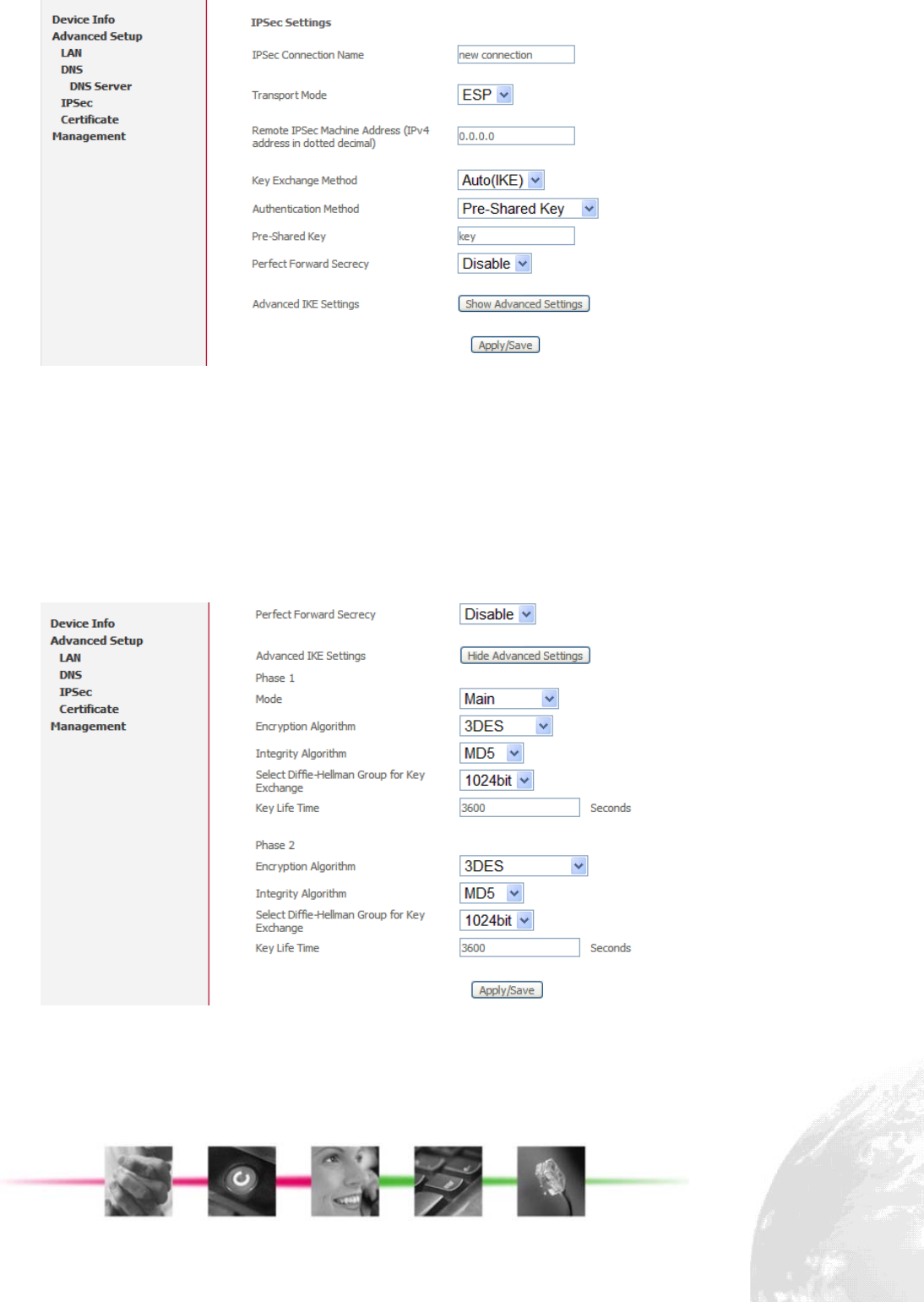
Figure 3-4-4. Advanced Setup – IPSec
This is a dynamic page. It will change itself by showing and hiding options when
different types or connections are chosen. User can select automatic key exchange
or manual key exchange, pre-shared key authentication or certificate authentication,
etc.
When automatic key exchange method is used, click “Show Advanced Settings” will
show more options: (Figure 3-4-5)
Figure 3-4-5. Advanced Setup – IPSec
Page 5
3.4.4. Certificate
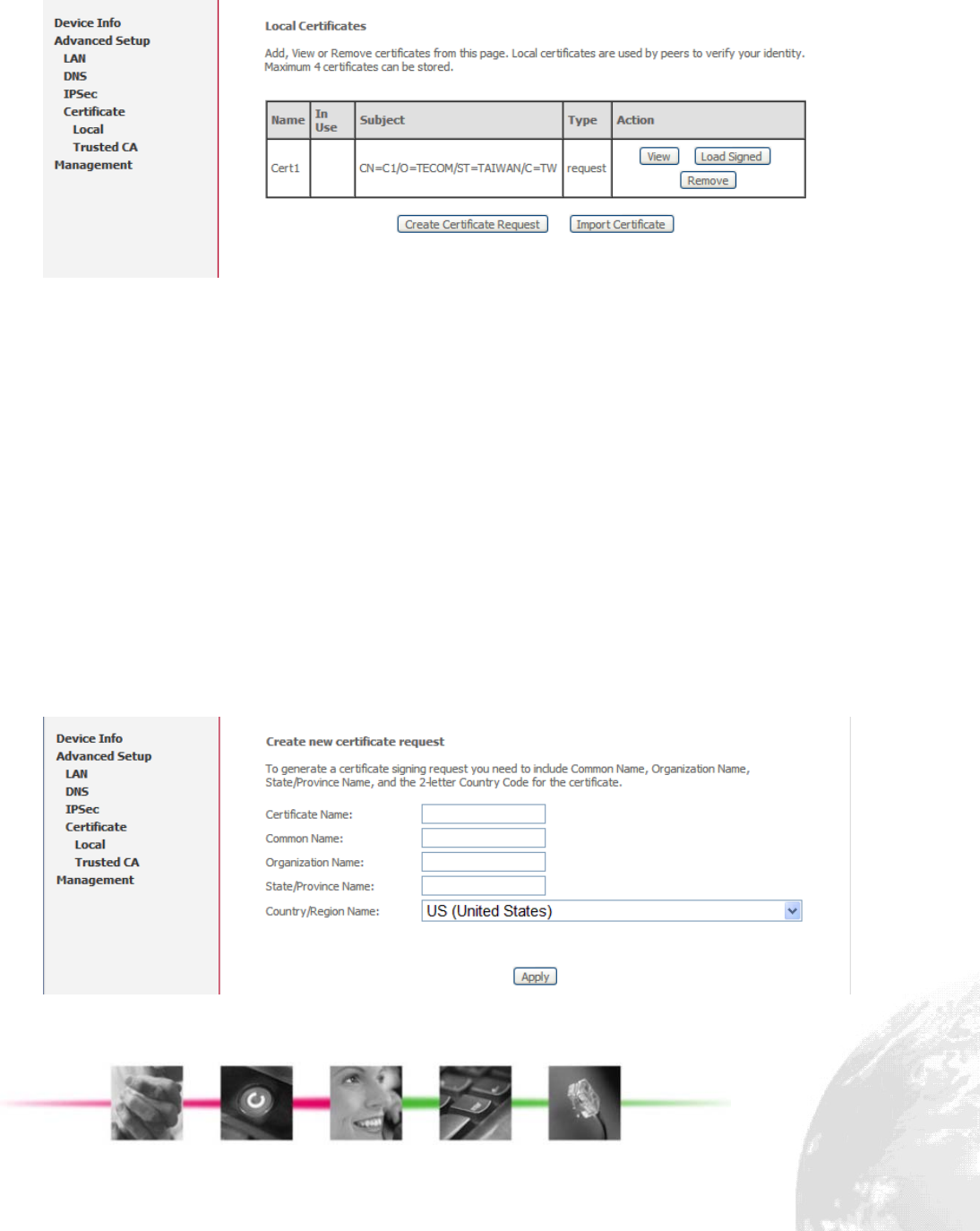
To use Certificate user interface, choose “Certificate” under “Advanced Setup” menu.
There are two menu items under “Certificate” menu: “Local” and “Trusted CA”. For
either type of certificate, the base screen shows a list of certificates stored in
FC1080-B1G-US. (Figure 3-4-6)
Figure 3-4-6. Advanced Setup – Certificate
In the menu, “Local” means local certificates. “Trusted CA” means trusted Certificate
Authority certificates. Local certificates preserve the identity of the device. CA
certificates are used by the device to very certificates from other hosts.
Local certificates can be created by two ways:
z Create a new certificate request, have it signed by a certificate authority and load
the signed certificate
z Import an existing signed certificate directly
Create New Local Certificate
Follow the following steps to create a new certificate:
Click “Create Certificate Request”, enter necessary information: (Figure 3-4-7)
Figure 3-4-7. Advanced Setup – Certificate
Page 6
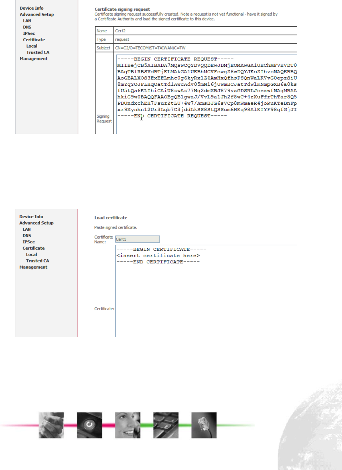
Wait several seconds, the generated certificate request will be shown: (Figure 3-4-8)
Figure 3-4-8. Advanced Setup – Certificate
The certificate request needs to be submitted to a certificate authority, which would
sign the request. Then the signed certificate needs to be loaded into device. Click
“Load Certificate” button from the previous screen or from the base screen will bring
up the load certificate page. Paste the signed certificate and click apply and a new
certificate is created. (Figure 3-4-9)
Figure 3-4-9. Advanced Setup – Certificate
Import Existing Local Certificate
To import existing certificate, click “Import Certificate” button and paste both
certificate and corresponding private key: (Figure 3-4-10)
Page 7
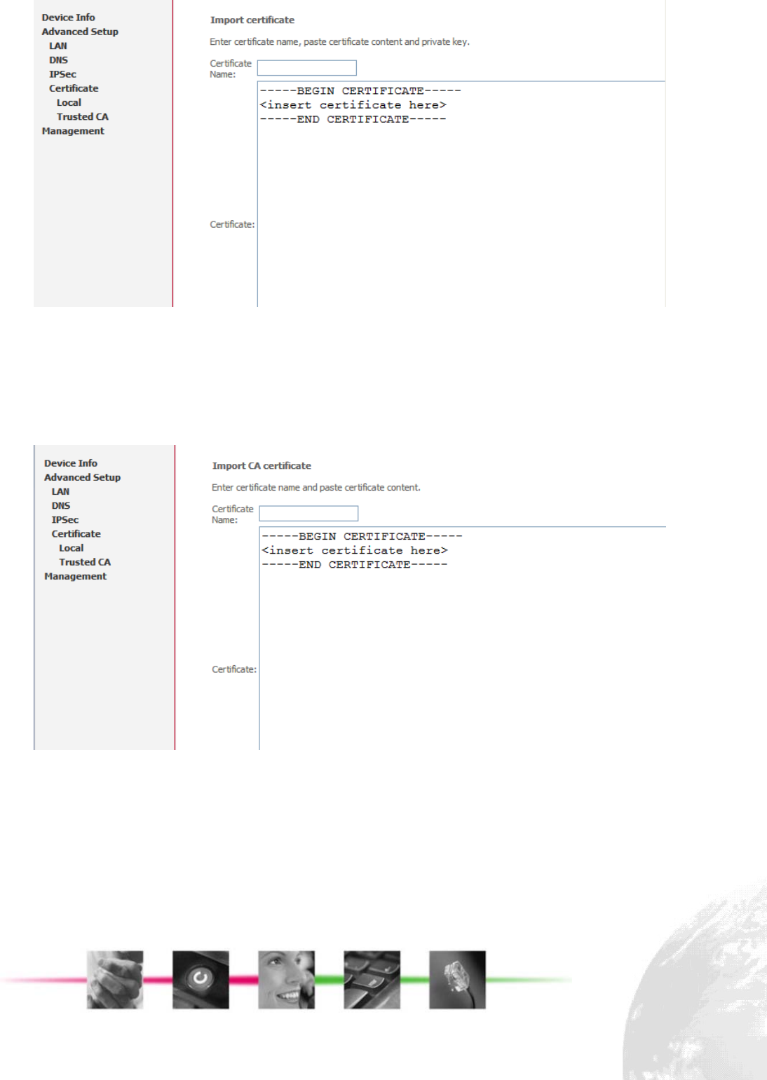
Figure 3-4-10. Advanced Setup – Certificate
CA Certificates
CA certificate can only be imported. The screen for importing is shown below:
(Figure 3-4-11)
Figure 3-4-11. Advanced Setup – Certificate
3.5. Management
3.5.1. Backup Settings and Restore Default Settings
Click “Management/Setting/Backup” on the left side of main page, it enables users to
save current configuration to a file, (Figure 3-5-1)
Page 8
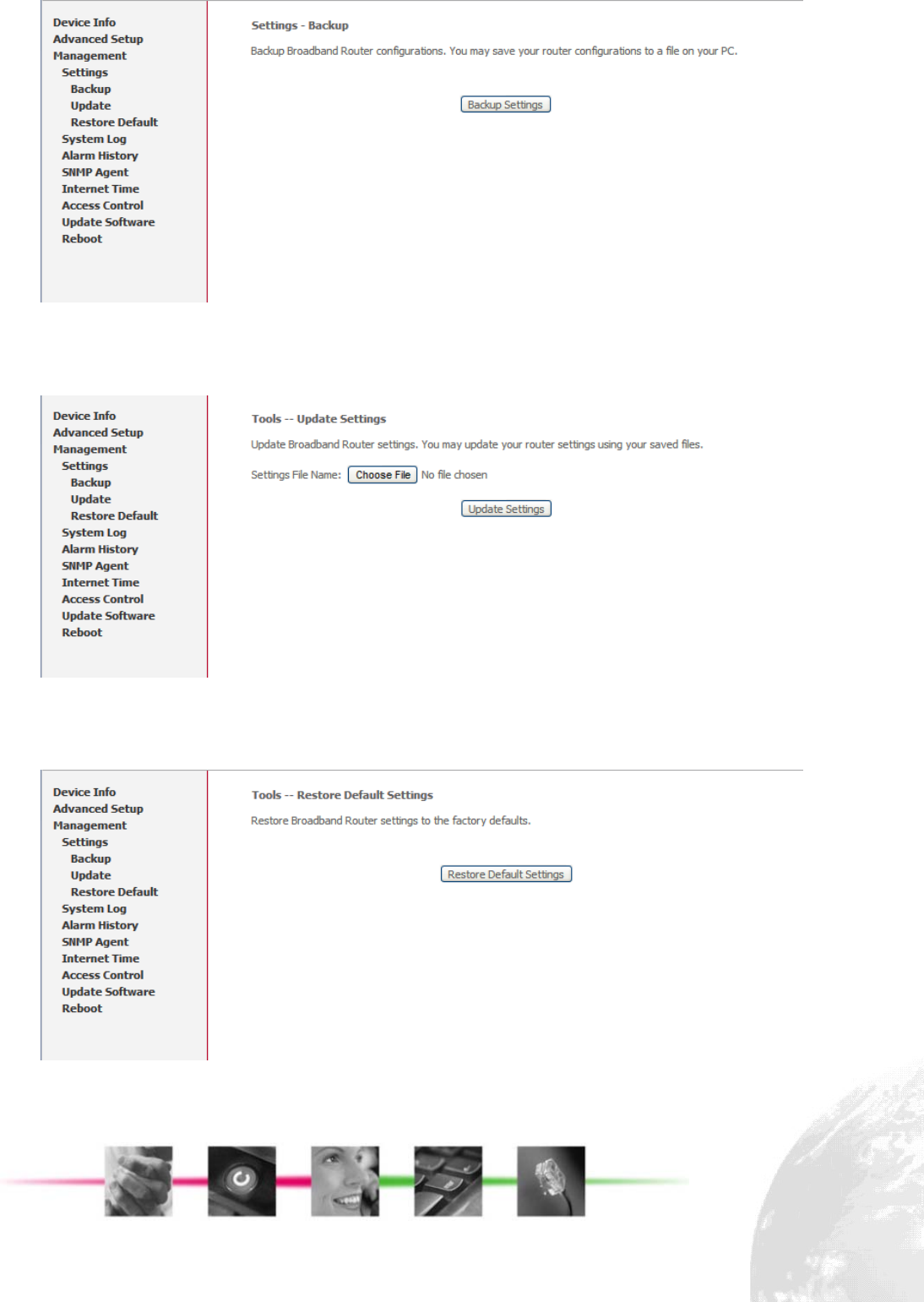
Figure 3-5-1 Management - Backup Settings
Click “Management/Setting/Update” on the left side of main page, it will allows users
to upload a saved configuration file for FC1080-B1G-US, in Figure 3-5-2,
Figure 3-5-2 Management - Update Settings
Click “Management/Setting/Restore Default” on the left side of main page, it will
allows users to reset all default settings for FC1080-B1G-US, in Figure 3-5-3,
Figure 3-5-3 Management - Restore default settings
Click the “Restore Default Settings” button, then system will reboot for a while.
Page 9
3.5.2. System Log
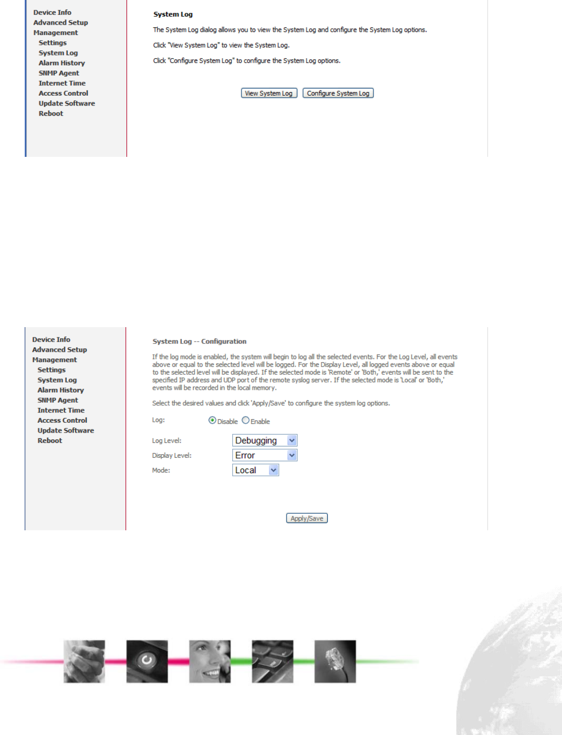
This allows System Administrator to view the System Log and configure the System
Log options. (Figure 3-5-4)
Figure 3-5-4 Management - System Log
Configure the System Log option.(Figure 3-5-5) There’re 8 levels of Log Level and
Display Level, Emergency, Alert, Critical, Error, Warning, Notice, Informational,
Debugging. The Log Level implies that what log level is applied to FC1080-B1G-US
to do the log. The Display Level would just show the users the log message that they
want to know. As a result, Display Level was just a subset of the retrieved from the
total log message which was logged according to the setting of the Log Level. If the
“Mode” is set to “Remote” or “Both”, the log messages would be sent to the specified
UDP port of the specified log server.
Figure 3-5-5 Management - System Log
3.5.3. Alarm History
This allows System Administrator to view the Alarm History and reset it. (Figure 3-5-6)
You can click “Reset” to clear and reset the Alarm History.
Page 10
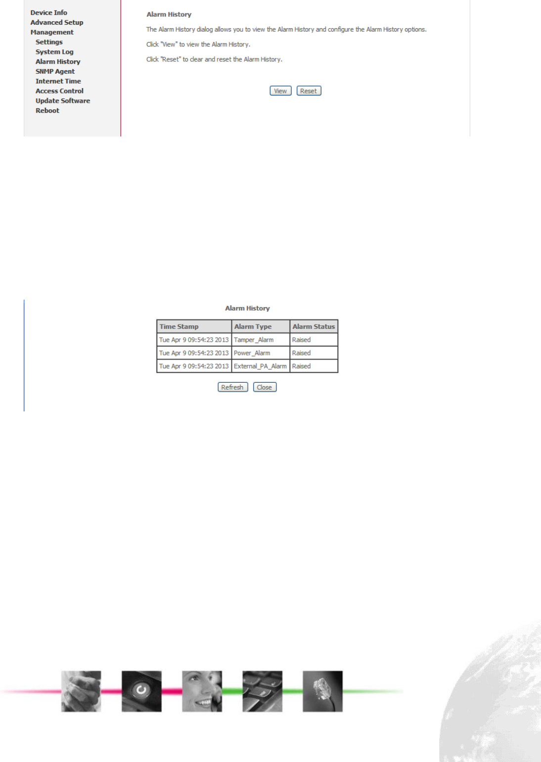
Figure 3-5-6 Management - Alarm History
Now there are four types of alarm: power, temperature, tamper, external PA. (Figure
3-5-7)
z Power Supply Monitoring alarms will be available for signalling over and under
power conditions
z Temperature Monitoring alarms will be available for signalling over and under
temperature
z Tamper alarms will be available to indicate that the Outdoor FAP has been
opened or tampered with
z External PA health alarms will be provided if PA bias voltage is out of
specification
Figure 3-5-7 Management - Alarm History
3.5.4. SNMP Agent
System Administrator could configure the embedded SNMP Agent here. SNMP
Agent would allow a management application to retrieve statistics and remote
control . (Figure 3-5-8)
Page 11
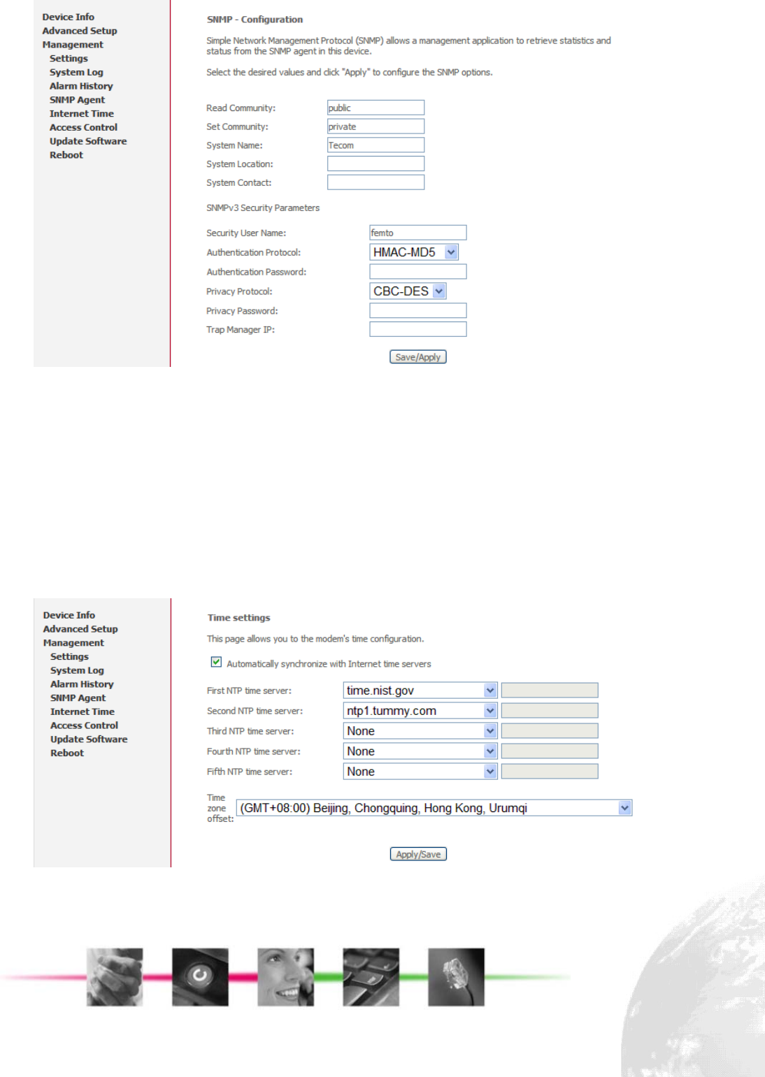
Figure 3-5-8 Management - SNMP Agent
The detail function of Read Community, Set Community, System Name, System
Location, System Contact, and SNMPv3 related parameters would not be described
here. Please check with your system administrator.
You can also check appendix for the private MIBs supported by FC1080-B1G-US.
3.5.5. Internet Time
If you need FC1080-B1G-US to sync time from NTP server, you need to access this
page to configure your local NTP information, see Figure 3-5-9, you need to choose
corresponding NTP server or configure them manually.
Figure 3-5-9 Management - Internet Time
Page 12
3.5.6. Access Control
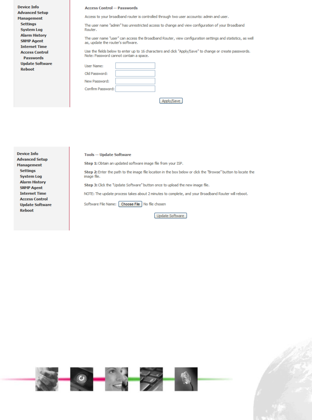
Access control enables to change password of different accounts. (Figure 3-5-10)
Figure 3-5-10 Management - Access Control
3.5.7. Update Software
Figure 3-5-11 show the web page, which is used for updating software,
Figure 3-5-11 Management - Update Software
The new released software could be updated from the PC. Click the “Choose File” to
locate the new software image file in the PC. Then, press “Update Software” to
proceed the software update.
It should be noticed that the update will take about more than 2 minutes; users
should wait for a while, and the FC1080-B1G-US will reboot by itself.
3.5.8. Reboot
This allows system administrator to reboot the FC1080-B1G-US carrier board
manually. (Figure 3-5-12)
Page 13
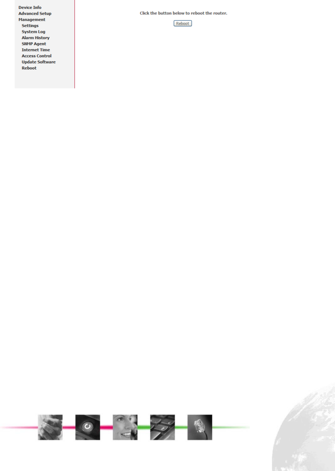
Figure 3-5-12 Management - Reboot
Page 14

Page 15
4. Appendix - MIB File
The following is part of TECOM Femto MIB file, it describes the node information of
TECOM MIB tree
-- 1.3.6.1.4.1.28044.1.1.1
femtoReset OBJECT-TYPE
SYNTAX Integer32
MAX-ACCESS read-write
STATUS current
DESCRIPTION
"femto module reset. set 1 to enable it."
::= { femtoObject 1 }
-- 1.3.6.1.4.1.28044.1.1.2
femtoFactoryReset OBJECT-TYPE
SYNTAX Integer32
MAX-ACCESS read-write
STATUS current
DESCRIPTION
"femto module factory reset. set 1 to enable it."
::= { femtoObject 2 }
-- 1.3.6.1.4.1.28044.1.1.3
carrierReset OBJECT-TYPE
SYNTAX Integer32
MAX-ACCESS read-write
STATUS current
DESCRIPTION
"carrier board reset. set 1 to enable it."
::= { femtoObject 3 }
-- 1.3.6.1.4.1.28044.1.1.4
carrierFactoryReset OBJECT-TYPE
SYNTAX Integer32
MAX-ACCESS read-write
STATUS current
DESCRIPTION
"carrier board factory reset. set 1 to enable it."
::= { femtoObject 4 }

Page 16
-- 1.3.6.1.4.1.28044.1.1.5
systemReset OBJECT-TYPE
SYNTAX Integer32
MAX-ACCESS read-write
STATUS current
DESCRIPTION
"whole system reset. set 1 to enable it."
::= { femtoObject 5 }
-- 1.3.6.1.4.1.28044.1.1.6
systemFactoryReset OBJECT-TYPE
SYNTAX Integer32
MAX-ACCESS read-write
STATUS current
DESCRIPTION
"whole system factory reset. set 1 to enable it."
::= { femtoObject 6 }
-- 1.3.6.1.4.1.28044.1.1.7
carrierTemperature OBJECT-TYPE
SYNTAX OCTET STRING
MAX-ACCESS read-only
STATUS current
DESCRIPTION
"Get the temperature of carrier board."
::= { femtoObject 7 }
-- 1.3.6.1.4.1.28044.1.1.8
caseOpen OBJECT-TYPE
SYNTAX Integer32
MAX-ACCESS read-only
STATUS current
DESCRIPTION
"case open status. 1-opened, 0-closed"
::= { femtoObject 8 }
-- 1.3.6.1.4.1.28044.1.1.9
simCardOpen OBJECT-TYPE
SYNTAX Integer32
MAX-ACCESS read-only
STATUS current
DESCRIPTION
"sim card open alarm.1-opened, 0-closed"
::= { femtoObject 9 }

Page 17
-- 1.3.6.1.4.1.28044.1.1.10
paTemperature OBJECT-TYPE
SYNTAX OCTET STRING
MAX-ACCESS read-only
STATUS current
DESCRIPTION
"Get the temperature of PA"
::= { femtoObject 10 }
-- 1.3.6.1.4.1.28044.1.1.11
currentOf28VDC OBJECT-TYPE
SYNTAX OCTET STRING
MAX-ACCESS read-only
STATUS current
DESCRIPTION
"current of front 28VDC."
::= { femtoObject 11 }
-- 1.3.6.1.4.1.28044.1.1.12
currentOf5VDC OBJECT-TYPE
SYNTAX OCTET STRING
MAX-ACCESS read-only
STATUS current
DESCRIPTION
"current of femto 5VDC."
::= { femtoObject 12 }
-- 1.3.6.1.4.1.28044.1.1.13
voltageOf28VDC OBJECT-TYPE
SYNTAX OCTET STRING
MAX-ACCESS read-only
STATUS current
DESCRIPTION
"voltage of front 28VDC."
::= { femtoObject 13 }
-- 1.3.6.1.4.1.28044.1.1.14
voltageOf5VDC OBJECT-TYPE
SYNTAX OCTET STRING
MAX-ACCESS read-only
STATUS current
DESCRIPTION
"voltage of femto 5VDC."
::= { femtoObject 14 }

Page 18
-- 1.3.6.1.4.1.28044.1.1.15
turnOnFemto5V OBJECT-TYPE
SYNTAX Integer32
MAX-ACCESS read-write
STATUS current
DESCRIPTION
"turn on femto 5VDC. 1-turn on,0-turn off"
::= { femtoObject 15 }
-- 1.3.6.1.4.1.28044.1.1.16
enablePA OBJECT-TYPE
SYNTAX Integer32
MAX-ACCESS read-write
STATUS current
DESCRIPTION
"enable PA. 1-enable, 0-disable"
::= { femtoObject 16 }
-- 1.3.6.1.4.1.28044.1.2
femtoTrap OBJECT IDENTIFIER ::= { femto 2 }
-- 1.3.6.1.4.1.28044.1.2.1
warmStartTrap NOTIFICATION-TYPE
STATUS current
DESCRIPTION
"warm start trap."
::= { femtoTrap 1 }
-- 1.3.6.1.4.1.28044.1.2.2
caseOpenAlarmTrap NOTIFICATION-TYPE
STATUS current
DESCRIPTION
"case open alarm trap."
::= { femtoTrap 2 }
-- 1.3.6.1.4.1.28044.1.2.3
simCardOpenAlarmTrap NOTIFICATION-TYPE
STATUS current
DESCRIPTION
"sim card open alarm trap."
::= { femtoTrap 3 }
-- 1.3.6.1.4.1.28044.1.2.4
powerAlarmTrap NOTIFICATION-TYPE
STATUS current
DESCRIPTION
"power alarm trap."
::= { femtoTrap 4 }

Page 19
-- 1.3.6.1.4.1.28044.1.2.5
thermalAlarmTrap NOTIFICATION-TYPE
STATUS current
DESCRIPTION
"PA thermal alarm trap."
::= { femtoTrap 5 }
-- 1.3.6.1.4.1.28044.1.2.6
externalPATrap NOTIFICATION-TYPE
STATUS current
DESCRIPTION
"power alarm trap."
::= { femtoTrap 6 }

FCC Regulations:
This device complies with part 15 of the FCC Rules. Operation is subject to the following two conditions: (1)
This device may not cause harmful interference, and (2) this device must accept any interference received,
including interference that may cause undesired operation.
Changes or modifications not expressly approved by the party responsible for compliance could void the user‘s
authority to operate the equipment.
****************************************************************************************************************************
This equipment has been tested and found to comply with the limits for a Class B digital device, pursuant to
part 15 of the FCC Rules. These limits are designed to provide reasonable protection against harmful
interference in a residential installation. This equipment generates, uses and can radiate radio frequency
energy and, if not installed and used in accordance with the instructions, may cause harmful interference to
radio communications. However, there is no guarantee that interference will not occur in a particular installation.
If this equipment does cause harmful interference to radio or television reception, which can be determined by
turning the equipment off and on, the user is encouraged to try to correct the interference by one or more of the
following measures:
—Reorient or relocate the receiving antenna.
—Increase the separation between the equipment and receiver.
—Connect the equipment into an outlet on a circuit different from that to which the receiver is connected.
—Consult the dealer or an experienced radio/TV technician for help.
****************************************************************************************************************************
FCC RF Exposure Information
This equipment complies with radio frequency (RF) exposure limits adopted by the Federal Communications
Commission for an uncontrolled environment. This equipment should be installed and operated with minimum
distance 20 cm between the radiator & your body.
****************************************************************************************************************************