User manual
IG6600 Administration Manual
Page 1 of 139
IG6600
Administration Manual
Copyright ©2010 TECOM Co., Ltd.
All Rights Reserved.

IG6600 Administration Manual
Page 2 of 139
Environment
The equipment you have purchased must not be disposed of with household waste. You
should return these to your distributor if they are to replace or dispose of them in an
approved recycling centre.
FCC Statement
This equipment generates, uses, and can radiate radio frequency energy and, if not
installed and used in accordance with the instructions in this manual, may cause
interference to radio communications. This equipment has been tested and found to
comply with the limits for a Class B computing device pursuant to Subpart J of Part 15 of
FCC rules, which are designed to provide reasonable protection against radio interference
when operated in a commercial environment. Operation of this equipment in a residential
area is likely to cause interference, in which case the user, at is own expense, will be
required to take whatever measures are necessary to correct the interface.
Important Notice :
1. The changes or modifications not expressly approved by the party responsible for
compliance could void the user’s authority to operate the equipment.
2. To comply with the FCC RF exposure compliance requirements, no change to the
antenna or the device is permitted. Any change to the antenna or the device could
result in the device exceeding the RF exposure requirements and void user’s
authority to operate the device.
CE Declaration of Conformity
This equipment complies with the requirements relating to electromagnetic compatibility,
EN55022 class B for ITE and EN 50082-1. This meets the essential protection
requirements of the European Council Directive 89/336/EEC on the approximation of the
laws of the Member States relating to electromagnetic compatibility.
Copyright Notice
All rights reserved. No part of this publication may be reproduced, transmitted, transcribed,
stored in retrieval system or translated in to any language or computer language, in any
form or by any means, electronic, mechanical, magnetic, optical, chemical, manual, or
otherwise, without the prior written permission of Company.
Company reserves the right to revise the publication and make changes from time to time
in the contents hereof without obligation of this company to notify person of such revision
or changes. The material contained herein is supplied without representation or warranty
of any kind. The Company therefore assumes no responsibility and shall have no liability of
any kind arising from the supply or use of this document or the material contained herein.
Trademarks
Windows 98/NT/2000/XP/7™and Internet Explorer™are registered trademarks of
Microsoft Corporation. All other companies, brands and product names are trademarks or
registered trademarks of their respective owners.
ISO-9001ISO-9001

IG6600 Administration Manual
Page 3 of 139
WARNING!
1. Read these installation instructions carefully before connecting the equipment to its
power adapter.
2. To reduce the risk of electric shock, do not remove the cover from the equipment or
attempt to dismantle it. Opening or removing covers may expose you to dangerous
voltage levels. Equally, incorrect reassembly could cause electric shock on re-use of
the appliance.
3. Do not expose the equipment to fire, direct sunlight or excessive heat.
4. Do not expose the equipment to rain or moisture and do not allow it to come into
contact with water.
5. Do not install the equipment in an environment likely to present a Threat of Impact.
6. You may clean the equipement using a fine damp cloth. Never use solvents (such as
trichloroethylene or acetone), which may damage the equipement’s plastic surface.
Never spray the equipment with any cleaning product whatsoever.
7. The equipment is designed to work in temperatures from 0oC to 45oC(32
oF to 104oF).
8. The equipment must be installed at least 1 meter from radio frequency equipment,
such as TVs, radios, hi-fi or video equipments (which radiate electromagnetic fields).
9. Do not connect the LAN/WAN port to any network other than an Ethernet network.
10.Do not attempt to upgrade your equipment in an unstable power environment. This
could cause unexpected damages.
11.Do not work on the system during lightning storms. Please disconnect all cables.
12.Children don't recognize the risks of electrical appliances. Therefore use or keep the
equipment only under supervision of adults or out of the reach from children.
13.No repair can by performed by the end user, if you experience trouble with this
equipment, for repair or warranty information, please contact your supplier.
Electrical Powering:
The IG6600 can be powered with correct power adaptor, the power adaptor must be
12V/1.5A. Any damage caused to the IG6600 as a result of using unsupported power
adaptors will not be covered by the manufacturer’s warranty.
Product Disposal Warning:
Ultimate disposal of this product, accessories, packing, especially the batteries should be
handled carefully for recycle and nature protection in accordance with national laws and
regulations.
!
IMPORTANT NOTE: To comply with the FCC RF exposure compliance requirements,
the antenna(s) used for this transmitter must be installed to provide a separation
distance of at least 20 cm from all persons and must not be co-located or operating in
conjunction with any other antenna or transmitter. No change to the antenna or the
device is permitted. Any change to the antenna or the device could result in the
device exceeding the RF exposure requirements and void user’s authority to operate
the device.

IG6600 Administration Manual
Page 4 of 139
Table Of Contents
1. Introduction .......................................................................................................................................................7
2. Getting to Know the IG6600...........................................................................................................................9
2.1 Front Panel ...................................................................................................................................................9
2.2 Rear Panel...................................................................................................................................................10
3. IG6600 Voice General Features..................................................................................................................11
3.1. Access Control for Web Page........................................................................................................11
3.2. Answering Position .......................................................................................................................11
3.3. Auto Attendant & Voice Mail........................................................................................................11
3.4. Auto Provisioning .........................................................................................................................12
3.5. Basic Call ......................................................................................................................................12
3.6. Call Abandon.................................................................................................................................12
3.7. Call Operator (Call Attendant) ......................................................................................................13
3.8. Call Pickup –Group......................................................................................................................13
3.9. Call Restriction..............................................................................................................................13
3.10. Call Routing ..................................................................................................................................14
3.11. Caller ID Detection/Generation ....................................................................................................14
3.12. Class Of Service (COS).................................................................................................................14
3.13. Daylight Saving Time ...................................................................................................................14
3.14. Default Set.....................................................................................................................................14
3.15. Direct In Dialing (DID).................................................................................................................15
3.16. Direct Inward System Access (DISA)...........................................................................................15
3.17. Emergency Call.............................................................................................................................15
3.18. Extension Password ......................................................................................................................15
3.19. Fax/Modem ...................................................................................................................................15
3.20. Flash –Analog Port (SLT) Flash Recognition...............................................................................15
3.21. Gateway to Gateway (IGW Group)...............................................................................................15
3.22. ICD Group (Hunt Group)..............................................................................................................16
3.23. IP Trunk.........................................................................................................................................16
3.24. Message Waiting Indication (MWI)..............................................................................................16
3.25. Music on Hold...............................................................................................................................16
3.26. Numbering Plan ............................................................................................................................17
3.27. Pause Insertion ..............................................................................................................................17
3.28. PSTN Backup................................................................................................................................17
3.29. Registration Server........................................................................................................................17
3.30. Service Mode ................................................................................................................................17
3.31. Station Message Detailed Recording (SMDR)..............................................................................18
3.32. System Speed Dial ........................................................................................................................18
3.33. System Time & Date .....................................................................................................................18
3.34. Trunk Group..................................................................................................................................18
3.35. Wizard Setup .................................................................................................................................18
4. IG6600 Voice Extension Features ..............................................................................................................20
4.1. Agent Log On/Off –ICD Group ...................................................................................................21
4.2. Alphanumeric Display...................................................................................................................21
4.3. Automatic Callback Busy..............................................................................................................21
4.4. Auto Hold......................................................................................................................................21
4.5. Call Fork........................................................................................................................................21
4.6. Call Forward..................................................................................................................................22
4.7. Call Hold .......................................................................................................................................22
4.8. Call Log.........................................................................................................................................22
4.9. Call Park / Call Park Answer.........................................................................................................23
4.10. Call Pickup –Individual................................................................................................................23
4.11. Call Waiting...................................................................................................................................23
4.12. Caller Blocking .............................................................................................................................23

IG6600 Administration Manual
Page 5 of 139
4.13. CO Flash........................................................................................................................................23
4.14. Conference – 3 Way ......................................................................................................................23
4.15. COS Following..............................................................................................................................23
4.16. Default Setting ..............................................................................................................................23
4.17. Distinctive Ringing .......................................................................................................................24
4.18. Do Not Disturb (DND)..................................................................................................................24
4.19. DSS/EDM .....................................................................................................................................24
4.20. Feature Key Programming ............................................................................................................24
4.21. Feature Button Reset .....................................................................................................................24
4.22. Hold Reminder ..............................................................................................................................24
4.23. LCD & Interactive Buttons ...........................................................................................................24
4.24. Multi-Line Appearance .................................................................................................................25
4.25. Mute ..............................................................................................................................................25
4.26. On Hook Dialing ...........................................................................................................................25
4.27. Paging (All/Group)........................................................................................................................25
4.28. Paging Allow/Deny .......................................................................................................................25
4.29. Phone Book ...................................................................................................................................25
4.30. Phone Lock/Unlock.......................................................................................................................26
4.31. Plug & Play ...................................................................................................................................26
4.32. Reminder Tone ..............................................................................................................................26
4.33. Service Mode Switching ...............................................................................................................26
4.34. Transfer .........................................................................................................................................26
4.35. Trunk Ring Type............................................................................................................................26
4.36. Volume Control .............................................................................................................................27
4.37. Web Management..........................................................................................................................27
5. Quick Installation............................................................................................................................................28
5.1 Connecting the IG6600...............................................................................................................................28
5.2 Wizard Setup ..............................................................................................................................................28
5.2.1 WAN Setting....................................................................................................................................28
5.2.2 LAN Setting.....................................................................................................................................30
5.2.3 Wireless Basic..................................................................................................................................31
5.2.4 Internet Time....................................................................................................................................31
5.2.5 Numbering Plan...............................................................................................................................32
5.2.6 IP Trunk ...........................................................................................................................................33
5.2.7 Call Routing Table ...........................................................................................................................34
5.2.8 Wizard Setup Finished.....................................................................................................................34
6. Configuration....................................................................................................................................................36
6.1 Setup...........................................................................................................................................................36
6.2 Establish The Connection...........................................................................................................................36
6.3 Device Info .................................................................................................................................................38
6.3.1 Summary..........................................................................................................................................38
6.3.2 Statistics...........................................................................................................................................38
6.3.2.1 LAN ..............................................................................................................................................38
6.3.2.1 WAN .............................................................................................................................................38
6.3.3 Route................................................................................................................................................39
6.3.4 ARP..................................................................................................................................................39
6.3.5 DHCP ..............................................................................................................................................40
6.4 Advanced ....................................................................................................................................................41
6.4.1 WAN ................................................................................................................................................41
6.4.2 LAN .................................................................................................................................................43
6.4.3 NAT .................................................................................................................................................43
6.4.4 Security............................................................................................................................................46
6.4.5 Parental Control...............................................................................................................................48
6.4.6 Quality of Service............................................................................................................................50
6.4.6.1 DSCP Marking..............................................................................................................................50
6.4.6.2 Bandwidth Control .......................................................................................................................50
6.4.7 Routing ............................................................................................................................................51
6.4.8 Dynamic DNS..................................................................................................................................52

IG6600 Administration Manual
Page 6 of 139
6.4.9 Upnp ................................................................................................................................................53
6.4.10 File Server......................................................................................................................................54
6.4.11 Print Server ....................................................................................................................................57
6.5 Wireless ......................................................................................................................................................61
6.5.1 Basic ................................................................................................................................................61
6.5.2 Security............................................................................................................................................63
6.5.3 MAC Filter ......................................................................................................................................66
6.5.4 Wireless Bridge................................................................................................................................66
6.5.5 Advanced .........................................................................................................................................67
6.5.6 Station Info ......................................................................................................................................70
6.5.7 Power Saving...................................................................................................................................70
6.6 Mobile Network..........................................................................................................................................71
6.6.1 3G Device........................................................................................................................................71
6.6.2 3G Credential Settings.....................................................................................................................71
6.6.3 3G Connection Setting.....................................................................................................................72
6.6.4 3G configuration..............................................................................................................................72
6.7 Voice ...........................................................................................................................................................74
6.7.1 Phone ...............................................................................................................................................74
6.7.2 Trunk................................................................................................................................................77
6.7.3 System .............................................................................................................................................85
6.7.4 Voice Mail........................................................................................................................................94
6.7.5 Registered Phone .............................................................................................................................99
6.8 Management .............................................................................................................................................100
6.8.1 Settings ..........................................................................................................................................100
6.8.2 System Log....................................................................................................................................102
6.8.3 TR-069 Client ................................................................................................................................103
6.8.4 Time Setting...................................................................................................................................103
6.8.5 Access Control...............................................................................................................................105
6.8.6 PTC................................................................................................................................................107
6.8.7 Update Software ............................................................................................................................107
6.8.8 Reboot............................................................................................................................................108
6.9 Diagnostics ...............................................................................................................................................109
6.9 Logout ......................................................................................................................................................110
Appendix 1: Product Summary..........................................................................................................................111
Appendix 2: Feature Access Codes..................................................................................................................114
Appendix 3: Auto Attendant and Voicemail System........................................................................................118
Appendix 3.1 System Voice Prompts .............................................................................................................118
Appendix 3.1.1 Preset Voice Prompts ....................................................................................................118
Appendix 3.1.2 Voice Prompts Recording..............................................................................................121
Appendix 3.2 Flowchart .................................................................................................................................122
Appendix 3.2.1 Automated Attendant ....................................................................................................122
Appendix 3.2.2 Subscriber Voicemail Flowchart ...................................................................................124
Appendix 3.2.3 Mailbox Administer Flowchart .....................................................................................126
Appendix 3.2.4 System Administrator’s Voicemail Flowchart...............................................................131
Appendix 4: PTS/PTC .........................................................................................................................................134
Install PTS ......................................................................................................................................................134
Update IG6600 Firmware...............................................................................................................................134
Update IG6600 Configuration File.................................................................................................................135
Receive IG6600 Configuration File ...............................................................................................................136
Show Update Log...........................................................................................................................................138
Set Working Time...........................................................................................................................................139
IG6600 Administration Manual
Page 7 of 139
1. Introduction
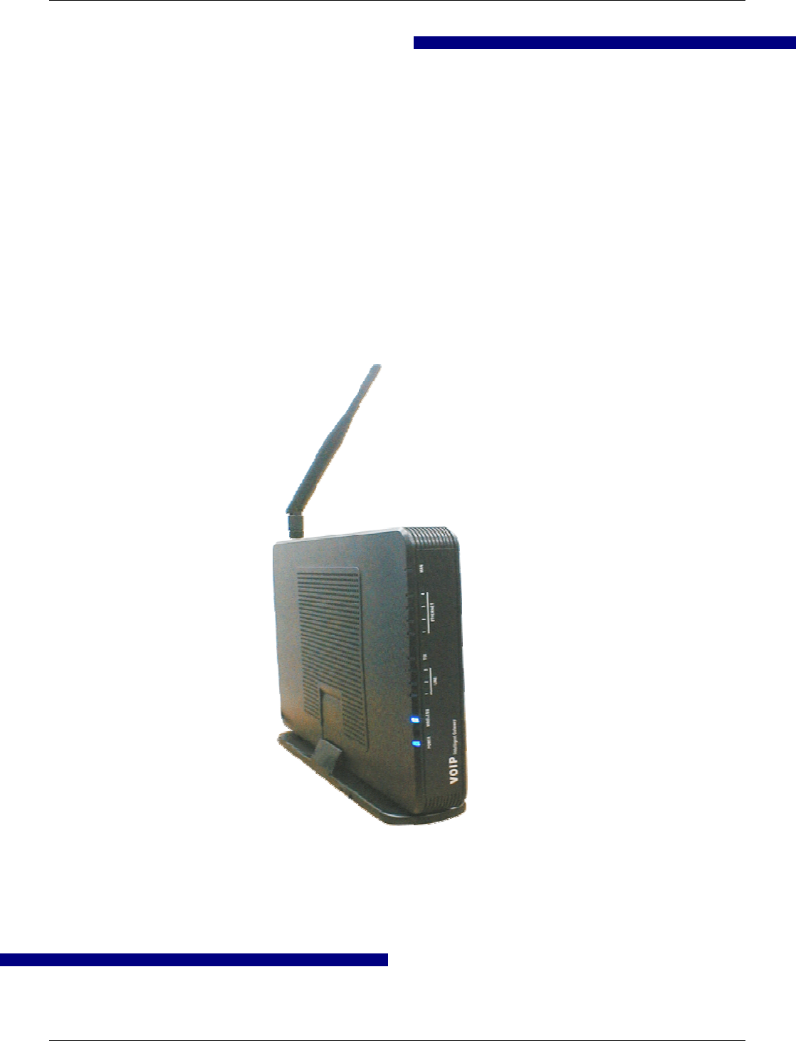
The Tecom IG6600 is an all-in-one solution which has rich feature set of IP PBX telephone
systems and IP networking systems. It has business essential PBX features such as an
auto-attendant, voice mail, multi-line appearances, three way call conferencing, intercom,
music on hold, call-forwarding and much more. The IG6600 system opens up access to
the benefits of VoIP, including low cost long distance service, and one network for both
voice and data.
The IG6600 is so easy to configure that a fully working system can be set up in minutes.
Plug and Play feature allows new telephones to be automatically detected and registered
when they are connected. The IG6600 is so easy to be managed and configured by its
integrated web server.
The IG6600 system can work with any SIP based IP Phone. However, it is the best to
work with Tecom’s IP Phones IP2032, IP2061 and IP2062 to take advantages of powerful
business features such as plug & play, all paging/group paging, multi line appearances,
etc….The IG6600 has a FXS port to support traditional analog devices such as telephone,
answering machine, FAX machine.
It must not be an ordinary Integrated Access Device (IAD) solution, nor a mere ATA
solution, but with elaborated and popular Voice-centric features, so as to be able to
penetrate conventional Voice-centric market
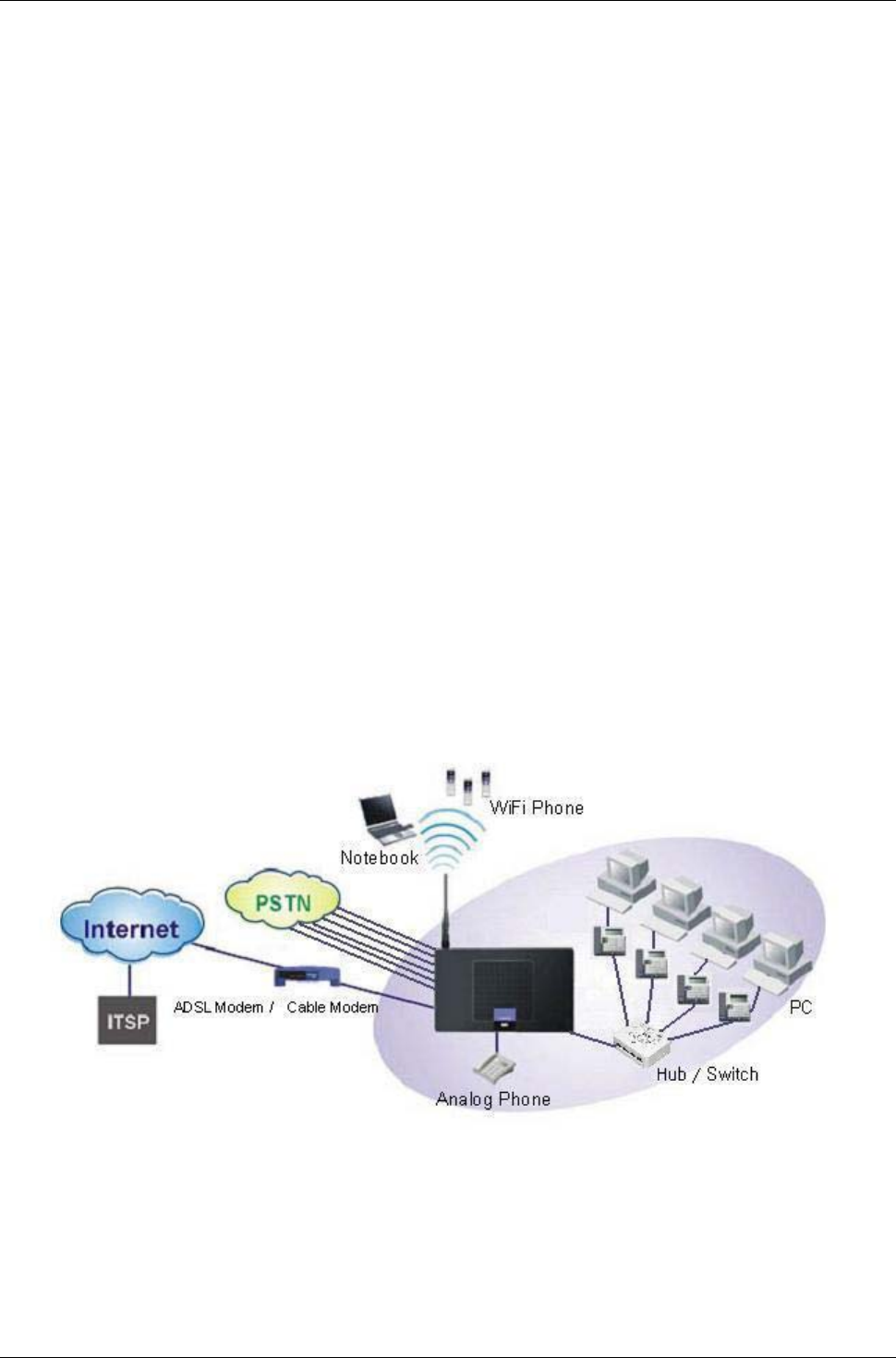
Interfaces
WAN Interface: 10BASE-T/100BASE-TX/1000BASE-T Gigabit Ethernet port
CO Interface: 6 FXO (Loop Start, for PSTN)
Analog Device Interface: 1 FXS (For Analog Telephone or FAX)
LAN Interface: 1 Ethernet (10BASE-T/100BASE-TX)
Built-in 802.11b/g/n WiFi access point

IG6600 Administration Manual
Page 8 of 139
USB Interface : Connects to your USB storage devices, USB printer or 3G
dongle.
Terminals
1 Analog Terminal (Analog Telephone or FAX)
24 IP Stations (Wired or WiFi IP-Phone)
Basically, the Administration is required to do the following things:
(1) To understand the architecture, resources, and devices of whole environment
which will be involved with the VoIP communications.
(2) To build a common setting file for most users.
(3) To configure each phone and install them into the network.
(4) To configure each interfaces and install them into IG6600.
(5) And to solve the problems that users encounter during operation.
IG6600 Administration Manual
Page 9 of 139
2. Getting to Know the IG6600
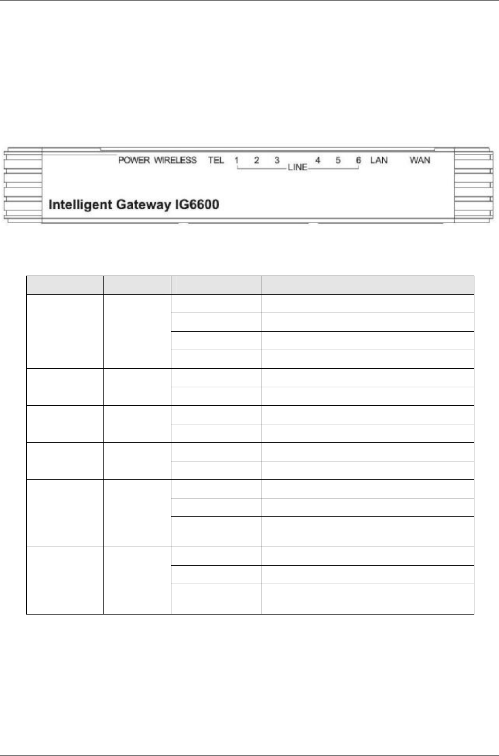
2.1 Front Panel
The front panel contains several LEDs that indicate the status of the IG6600.
Figure 2-1. Front Panel of IG6600
LED Name Color Status Description
Red On Firmware updating
Blue Flashing System booting up
Blue On System initialized and running
POWER Red/Blue
Off Power off
On Wireless LAN is activeWIRELESS Blue
Off Wireless LAN is idle
Off PSTN Line is idleLINE (1-6) Blue
On PSTN Line is active
Off Phone is idleTEL Blue
On Phone is active
On LAN is connected
Off LAN is not connected
LAN Blue
Flashing LAN activity present (traffic in either
direction)
Blue On WAN is connected and IP is obtained
Red On WAN is not conneced or no IP assigned
WAN Red/Blue
Flashing WAN activity present (traffic in either
direction)

IG6600 Administration Manual
Page 10 of 139
2.2 Rear Panel
The rear panel contains the ports for the IG6600's data and power connections.
Figure 2-2. Rear Panel of IG6600
Label Function
WAN RJ-45 connector: Connects the device to your cable modem, or to your
ADSL Modem. It’s to connect to the remote network.
LAN RJ-45 connector: Connects the device to your PC's Ethernet port, or to the
uplink port on your LAN's hub.
Line (1-6) RJ-11 connector: Connects the device to your PSTN lines.
TEL RJ-11 connector: Connects the device to your analog phone.
USB Connects to your USB storage devices, USB printer or 3G dongle
Power Connects to the supplied power converter cable.

IG6600 Administration Manual
Page 11 of 139
3. IG6600 Voice General Features
3.1. Access Control for Web Page
The Access Control settings allow the System Administrator to configure the Web Port,
Service Control List, IP Address Access Control mode and password for Administrator,
Supporter and User.
IG6600 also provide an external user access to the internal IP phone’s Web page. The
Registered Phone page will list all registered phones with their IP links. Clicking a
specific link will open that specific IP phone’s Web page.
IG6600 provides three Access mode for Web Page
- Administrator mode: unrestricted access and program
- Support Mode: allow an ISP technician to maintain and run diagnostics
- User Mode: view some configuration settings and statistics.
3.2. Answering Position
For incoming calls from the Public Switched Telephone Network (PSTN) (via analog CO
or FXO ports), the IG6600 provides the flexibility to ring specific destinations. The
IG6600 provides the ability to ring Auto Attendant. The IG6600 also provides the ability
to simultaneously ring up to 24 extensions when programmed in a ICD Hunt Group, or
the Operator in accordance with the system service mode (day or night). The user can
also assign a line to ring directly to an extension. Incoming VoIP calls from a registered
ITSP can be programmed and routed in the same manner as the analog CO (FXO)
ports.
3.3. Auto Attendant & Voice Mail
The IG6600 Auto Attendant can greatly enhance business productivity by providing
either a full-time automated attendant to handle all incoming system calls or part-time
automated attendant to handle overflow traffic. The Voice Mail Module provides up to 16
hours recording time that are shared by all extensions. The system can handle four
simultaneous calls with following functions.
•Auto Attendant Functions
The Auto Attendant provides an incoming caller with a customized welcome greeting
and specific prompts that will describe the options available to the caller.
Play the welcome greeting messages depending on the system service
mode: Day, Night, Noon, and Holiday.
Route the call to the appropriate destination (extension or UCD group) with
the dialing digits.
Leave a message to a particular mailbox.
Make an outside call via another trunkline (PSTN or SIP-Trunk).
•Voice Mail Functions

IG6600 Administration Manual
Page 12 of 139
Delete, save, or skip messages.
Forward messages to other mailboxes.
Envelop information indicating the time and date of the message received;
sender information will also be included in the email notification.
Change personal greeting and password.
Expert mode support (playback controls when reviewing messages).
Send a notification via email when a new message is left.
Send voice message as the attachment of the email in WAV format.
The maximum recording length for each call is 1800 seconds.
When 90% of the VM size is used, it shows “Message Full”on the all
IP20xx’s LCD.
For each extension, the maximum number of Voice Mail is 200.
For each leaving message, it's saved 1 - 7 days or infinite
•Voice Messages
Provide two languages service for the all voice files.
Provide G711-ulaw voice files.
Administrators can record the all voice messages by themselves.
Administrators can update, backup or delete the all voice messages from/to
the PC.
3.4. Auto Provisioning
WAN Management Protocol (TR-069) allows an Auto-Configuration Server (ACS) to
perform auto-configuration, provision, collection, and diagnostics to this device.
Firmware upgrade or vendor configuration file backup can be done remotely on ACS
server. Select the desired values and click "Save Settings" to configure the TR-069 client
options.
IG6600 also provides an Auto Provision Server (APS) to update IG6600 FW, Update /
Retrieve IG6600 Configuration and the registered IP20xx FW
3.5. Basic Call
To make an intercom call, dial a Station number (IP Terminal, POTS) or a Voice Mail
number.
To make an outside call, dial a phone number. IG6600 chooses a line (PSTN line, IP
trunk, another IG6600) via Call Routing Table to dial out. If it includes “p”in the phone
number, and the call is dialed through PSTN Trunk, it will pause for a pre-configured
time.
To make an outside call, dial a PSTN, an IP Trunk or a Trunk Group number first. After
hearing dial tone, dial the phone number.
3.6. Call Abandon
For every PSTN call, IG6600 provides the facility to monitor the call status. If the remote
party hangs up, the ongoing call must be terminated.

IG6600 Administration Manual
Page 13 of 139
The PSTN line monitor is accomplished through monitoring the loop-break signal,
polarity reversal or busy tone. The value range of loop-break signal is:
0/100/200/…/1000 ms.
3.7. Call Operator (Call Attendant)
IG6600 supports one operator. Any extension can be designated as the operator
through system configuration.
One primary operator may be assigned in the system. The standard IP phone will serve
as the operator telephone. When assigned as operator, this extension supports general
system functions.
While the internal extension dials Operator Directory Number ("0" at default), or the
outside party dials "0" when Auto Attendant plays the welcome message, these calls will
be stored into Operator Queue. The Operator is First-In-First-Out to service these calls.
At the waiting time, the calling party will be on Music-On-Hold state.
A second (alternate) operator position may be designated for common sharing of
incoming operator calls during peak traffic period.
3.8. Call Pickup –Group
You may answer trunk calls at another extension using the function. The feature allows
you to easily access calls ringing via the single digit “*”.
3.9. Call Restriction
IG6600 provides sophisticated monitoring of digits dialed on PSTN/IP Trunks. If a digit or
range of digits dialed on a Trunk line is inconsistent with the dialing extension’s COS, the
call is denied. This calling COS criteria can be applied to local calls, long distance calls,
and specific numbers that are considered allowed in areas where other numbers may be
restricted.
In the call restriction table, it provides the following programming items:
•
From/To
The allowed intervals are made up of a From and To entry which establish a
numeric range. For example, an entry of “From 1700” , “To 1800”would include
the following range of numbers as the leading: 1700, 1701, 1702, …1799, 1800.
Each From/To entry can be from 1 to 13 digits long and may contain any digit 0-9.
The “From”entry must be less than or equal to the “To”entry.Each From/To entry
can be from 1 to 13 digits long and may contain any digit 0-9, or X (X representing
any digit). The :From”entry must be less than or equal to the “To”entry.
•
Trunk Access
IG6600 checks the field only when a call matches the associated allowed
interval. If the field is set to “Y”, the entry is valid when the trunk is accessed
previously. If the field is set to “N”, the trunk isn’t accessed previously. The trunk
will be accessed through Call Routing Table. If he option is set to “YN”, the entry
is valid no matter the trunk is accessed or not previously.
•
COS
The COS setting is defined by the allowed intervals. “Y”allows an extension with
the COS or higher priority to dial the number(s) specified in that range.

IG6600 Administration Manual
Page 14 of 139
3.10. Call Routing
The Call Routing feature automatically routes outgoing calls using the most appropriate
route. The appropriate route is determined based on the number dialed. If necessary,
IG6600 can automatically modify the dialed number by deleting and inserting digits.
The call routing destination is a PSTN line, an IP line, a line group or another IG6600. It
allows you to configure each entry in the Call Routing Table which contains a routing
rule for outgoing calls:
- From/To setting defines the number range
- Min/Max defines the match length
- Del/Insert can change the target number
- Destination defines the outbound call interface trunk
3.11. Caller ID Detection/Generation
IG6600 provides the ability to detect the calling party identification provided by CO via
PSTN lines or by Uplink Server via IP trunks. This data when received by the telephone
carrier will be displayed on all ringing IP phones.
IG6600 also provide Caller ID Generation to the Caller ID equipped Single Line
Telephone.
3.12. Class Of Service (COS)
IG6600 provides 8 Classes of Service (COS) for assignment of outside line
dialing-privileges. Each extension may be assigned one Day-COS and one Night-COS.
The Extension COS is primarily used for restriction and control of long distance dialing.
COS 0 is the highest priority. COS 7 is the lowest one.
3.13. Daylight Saving Time
Daylight Saving Time (DST) feature supports auto adjustment for daylight saving time. It
allows you to configure the Daylight Saving Time (DST) which includes support for auto
adjustment of daylight saving time.
- Internet Time: it obeys the international standard rule.
- Manual DST Rule: it allows you to define your own Daylight Savings Time Rule.
3.14. Default Set
Clear all settings and return the IG6600 set to the factory condition.
When rebooting the IG6600 to the default, some settings for the registered Tecom IP
Phones (IP2032, IP2061 and IP2062) are reset to the default also.
-LineKeys
- Call Forward
- DND
- Page Deny
- Auto Answer
- Phone Lock
- Call Waiting

IG6600 Administration Manual
Page 15 of 139
3.15. Direct In Dialing (DID)
IG6600 provides a Direct In Dialing Table for IP Trunks. It will be able to offer its
individual phone number for each extension.
IG6600 provides 50 entries in the Direct In Dialing Table. Each entry includes
- DID Number
- Outgoing Call ID
- Extension Number
-DisplayName
3.16. Direct Inward System Access (DISA)
The feature allows you to remotely access IG6600 lines to make the outside calls. The
current PSTN/IP lines are all DISA lines. While ringing to Auto Attendant, the outside
callers have direct access to extensions, PSTN/IP lines, Call Routing and Trunk Groups.
The out-calling is secured by means of verified passwords against the assigned
extension number. The use is accomplished only when a valid extension number has
been entered and when the password entered matches that stored for the extension
number entered.
3.17. Emergency Call
IG6600 allows you configure five Emergency Call numbers and lines with which
Emergency Calls are sent out. Any user can make an Emergency Call regardless of its
Call Routing table, Call Restriction, and Phone Lock, when they dial a pre-configured
Emergency Call number. The numbers of Emergency Call must not collide with the
numbers in Numbering Plan.
It allows to program 5 emergency numbers. “911”is in it by default.
3.18. Extension Password
All extensions of the IG6600 system have an associated User Password. The Password
is applied to Voice Mail service, and some system feature settings (Phone Lock, COS
Following, DISA).
3.19. Fax/Modem
IG6600 supports FAX/modem tone detection and auto-fallback to G.711.
3.20. Flash –Analog Port (SLT) Flash Recognition
Flash is the momentary operation of the hook-switch at the analog device, which can be
deciphered by the IG6600 system in such a way that the previous call in progress is held,
or placed in a status of transfer awaiting further instructions from the user.
3.21. Gateway to Gateway (IGW Group)
A call may be placed from one IG6600 to another IG6600 via the Call Routing Table.
The call Routing Table allows the user to make a direct call to an extension in another

IG6600 Administration Manual
Page 16 of 139
IG6600 It also allows the user to share the PSTN or IP Trunks in another IG6600 to
make an outside call.
In an IGW Group, one Master IG6600 and at most 9 Slave IG6600s are available. Master
IG6600 must have a public/static IP address. Master and all Slave IG6600 share one
password for authentication. If the IP address of Master is set in a Slave IG6600, Slave
IG6600 sends its IP address, name, and password to the Master. Master IG6600 verifies
the received password and name. If the password is valid and the name is not duplicated,
Master IG6600 sends the IGW list to all Slave IG6600s.
3.22. ICD Group (Hunt Group)
IG6600 supports 4 ICD Groups. Each ICD Group can have up to 25 members. There are
three kinds of ICD Group mode –All Ring, Linear, and Distributed. For All Ring mode,
incoming Trunk calls ring all member extensions simultaneously. For Linear mode,
incoming call is put into a queue and then distributed from the first extension. For
Distributed mode, it is the same as Linear but selection of an extension is uniformed.
If more than one call rings at the same time, the first agent to go off hook will be
connected to the call that has been ringing the longest.
For unanswered Trunk call, it will be forwarded to a Reroute destination. The Reroute
destination can be Auto Attendant or the first member’sVoiceMailbox.
The missed ICD Group calls are recorded in ICD Call Log. It records the last 100 missed
ICD Group calls.
3.23. IP Trunk
IG6600 can register up to 8 SIP Uplink Servers. The extensions may make a call to the
users of the Uplink Servers, or any user in the world through the Uplink Servers.
•SIP messages, including INVITE, re-INVITE, ACK, CANCEL, OPTIONS, BYE,
REGISTER, INFO, REFER, SUSCRIBE/NOTIFY and REPLACE messages
•SIP Proxy, SIP Outbound Proxy, Registrar, and Outbound Registrar
•Auto Registration when Power-on or period
•Session Timer support
•Support IP address, domain name, user name, display name for SIP URL.
3.24. Message Waiting Indication (MWI)
It’s a Voice Mail feature. When somebody leaves messages, the router will inform the
phones, and phones’LCD will display new voice mails information, and its lamp will flash
accordingly.
3.25. Music on Hold
Any PSTN/IP line calls placed on hold will give music to the other external party.

IG6600 Administration Manual
Page 17 of 139
3.26. Numbering Plan
The Numbering Plan refers to the structure of dialed access to the various resources
that are part of the system. IG6600 also allows for a very flexible configuration
numbering for the various system resources.
IG6600 provides the following resources to be programmed in Numbering Plan.
•Extension Number
•Operator Number
•Voice Mail Service Number
•PSTN Line Number
•IP Trunk Numbers
•All Paging Number
•Paging Group Number
•ICD Group Number
•System Speed Dial Number
•Call Park Number
•Pick Up Number
3.27. Pause Insertion
Pause Insertion is used to generate an intentional delay in dialing on Outgoing FXO line
calls. A pause can or a combination of pauses may be stored in the dialed number, Call
Routing Table or a Speed Dial number. It uses “P”or “p”as the Pause digit.
3.28. PSTN Backup
In case of power failure, IG6600 automatically switches the first PSTN line to the
Single-line analog phone. The other PSTN lines are not supported
3.29. Registration Server
The IG6600 combines Proxy and Registrar servers in its application. For a Registrar
server, it acts as the front end to the location service for a domain, reading and writing
mappings based on the contents of REGISTER requests. The location service is then
typically consulted by a Proxy server.
3.30. Service Mode
IG6600 provide Day and night settings for each weekday in service mode page. And
during different time, Trunk incoming call will be forwarded to different extensions
according to the settings.

IG6600 Administration Manual
Page 18 of 139
3.31. Station Message Detailed Recording (SMDR)
The feature allows the administration to track all incoming and outgoing outside call
traffic, chronologically by extension number. SMDR is output from the standard Syslog
(None/LAN/WAN/Both)
SMDR information includes Trunk Line used, extension number, time and date the call
was placed, number dialed, duration of the call. IG6600 will also provide Outgoing Call
Duration Start Time to the PSTN call.
3.32. System Speed Dial
IG6600 stores frequently dialed numbers. These Speed Dial Numbers are accessed for
dialing by the associated Speed Dial Directory Numbers. The Speed Dial Directory
Numbers are assigned in Numbering Table. The Speed Dial is only for outgoing calls.
IG6600 stores up to 100 Speed Dial Numbers. In the Speed Dial Number, it’s allowed to
store Phone number up to 20 digits in length. Call Restriction and Call Routing are
applied and extensions may utilize only those numbers allowed based on their extension
COS. The actual dial sent to trunk is not displayed on IP phone’s LCD.
3.33. System Time & Date
The IG6600 system provides a built-in time clock to track System Time for reference in
certain features such as day/night service mode. This clock has the ability to
automatically adjust with network NTP server through internet.
System Time & Date can be applied to Tecom IP20xx Phone if it’s on IG6600’s LAN side,
or on WAN side with the same Router as IG6600’s..
3.34. Trunk Group
The Trunk Group feature is used to assign each PSTN Trunk and IP Trunk to a specific
Trunk Group. Each Trunk can be assigned to only one Trunk Group. The Trunk group
assignment is used for Trunk pool access. If setting some PSTN trunks and some IP
trunks into the same Trunk Group, the trunk access sequence will depend on the access
priority. The GW6000 provides up to 4 Trunk Groups. All PSTN Trunks are assigned to
default Trunk Group 1 and all IP Trunks are assigned to default Trunk Group 2. For the
four groups you can choose IP first or PSTN first if programming PSTN and IP Trunk in
the same group. This will take effect if call routing entry’s destination has been set as
Group choice
3.35. Wizard Setup
The IG6600 has a setup Wizard that provides the system administrator with a series of
step-by-step operations. The setup Wizard starts automatically when the IG6600 is
powered up for the first time, or if the system is reset to default configuration via the
reset switch on the IG6600 unit. The following programming/operation areas are
supported through the setup Wizard:

IG6600 Administration Manual
Page 19 of 139
•WAN Setting
•LAN Setting
•Wireless Basic
•Wireless Security
•Internet Time
•Numbering Plan
•IP Trunk
•Call Routing Table

IG6600 Administration Manual
Page 20 of 139
4. IG6600 Voice Extension Features
IG6600 follows SIP standard to serve SIP phones. Basically, telephone features that
meets SIP standard can be applied in IG6600.
Tecom IP20xx phone (IP2032/IP2061/IP2062) supports many phone features. But for
adding some traditional KTS features that are not defined definitely in SIP protocol,
some specified information are transmitted between IG6600 and IP2xxx Phones. This
section introduces these special phone features. Some features are only for IP20xx
phones and/or FXS phone.
The following features depend on whether the phone provides.
Feature Tecom
IP20xx
FXS Other
SIP Phone
Agent Log On/Off –ICD Group Yes Yes No
Alphanumeric Display Yes Depends Depends
Automatic Callback Busy Yes Yes No
Auto Hold Yes No Depends
Call Fork Yes Yes No
Call Forward –Direct Yes Yes Depends
Call Forward –Busy Yes Yes Depends
Call Forward –No Answer Yes Yes Depends
Call Forward –DND Yes Yes Depends
Call Forward –Follow Me Yes Yes No
Call Hold Yes Yes Depends
Call Log Yes No Depends
Call Park Yes No No
Call Park Answer Yes Yes Yes
Call Waiting Yes Yes Depends
Caller Blocking Yes No Depends
CO Flash Yes No No
Conference 3 Way Yes No Depends
COS Following Yes Yes No
Default Setting Yes Yes Depends
Distinctive Ringing Yes No Depends
Do Not Disturb Yes Yes Depends
DSS/EDM IP2061 Only No No
Feature Key Programming Yes No No
Flash –CO/PBX Lines Yes Yes No
Hold Reminder Yes Yes Depends
LCD & Interactive Buttons Yes No Depends
Multi-Line Appearance Yes No Depends
Mute Yes No Depends
On Hook Dialing Yes Depends Depends
Page (All/Group) - Paging Yes Yes Yes
Page (All/Group) - Paged Yes No No
Page Answer Yes No No
Page Allow / Deny Yes No No
Phone Book Yes No Depends

IG6600 Administration Manual
Page 21 of 139
Phone Lock/Unlock Yes Yes No
Plug and Play Yes Yes No
Reminder Tone Yes Yes Depends
Service Mode Switching Yes Yes No
Transfer Yes Yes Depends
Trunk Ring Type Yes Yes Depends
Web Management Yes No Depends
Volume Control Yes Depends Depends
NOTE: the word “Depends”means that the features depend on whether the phone
provides.
4.1. Agent Log On/Off –ICD Group
Extensions can log on or log off from ICD group.
Enable Agent Log On feature, dial *91.
Disable Agent Log On feature, dial **91.
If an extension disables the Agent Log On feature, the extension should log off from all
ICD groups it belongs to.
4.2. Alphanumeric Display
The IP Phone extension provides a graphic LCD that supports 64 alphanumeric
characters. The LCD enhances many system features.
4.3. Automatic Callback Busy
IP20xx supports Automatic Callback Busy. When the callee has no session resource,
the caller will hear busy tone.
The caller can dial “6”to get the Automatic Callback Busy feature.
The confirmation tone will be heard and come back to idle status. When the callee is no
longer in busy status, the caller will hear call back ring.
Disable the Automatic Callback Busy feature, dial *66.
4.4. Auto Hold
You may enable the feature to simplify call handling and avoid accidental “lost”calls.
Hold will automatically place any call that is currently connected at your phone on hold
whenever a Trunk line button is pressed.
4.5. Call Fork
IG6600 supports to ring another extension or an outside destination via IP Trunk
simultaneously when the extension gets an incoming call. When the call is answered by
one of the both parties, the call at the other party will stop ringing automatically.
To Activate (Type: 0 – ICM; 1 –Outside; 2 –Both)
*26 + Type + Ext No
*26 + Type + * + (PSWD) + * + Outside Number
To Cancel
**26
Call Fork is executed if Caller is IP20xx, FXS or Trunk. Call Fork is not applied to
Operator call, Paging call and ICD call

IG6600 Administration Manual
Page 22 of 139
4.6. Call Forward
Call Forwarding reroutes incoming calls from one extension to another destination. The
destination of a call forward can be another extension, voicemail box or an outside
phone number (External Call Forward; ECF).
IG6600 support the following feature access codes to program Call Forwards for IP20xx
and FXS. It includes a “Type”setting for each Call Forward. It can be programmed to
“ICM”,“Outside”or “Both”(Type: 0 –ICM, 1 –Outside, 2 –Both).
Direct Call Forward:
Forward all of the calls without regard to the extension status.
To enable, dial *21 + Type + Ext/VAA/ICD No.
*21 + Type + * + (PSWD) + * + Outside Number
To disable, dial **21.
Busy Call Forward:
Forward the calls if the extension is busy.
To enable, dial *22 + Type + Ext/VAA/ICD No.
*22 + Type + * + (PSWD) + * + Outside Number
To disable, dial **22.
No Answer Call Forward:
Forward the calls if the extension doesn’t answer the call within No Answer
Time.
To enable, dial *23 + Type + Ext/VAA/ICD No + * + Time.
*23+Type+*+(PSWD)+*+OutsideNumber+*+Time
To disable, dial **23.
DND Call Forward:
Forward the calls if the extension enabled DND.
To enable, dial *24 + Type + Ext/VAA/ICD No
*24 + Type + * + (PSWD) + * + Outside Number
To disable, dial **24.
Follow Me Call Forward:
Forwards calls at your extension to the extension where tou are currently
working.
To enable, dial *25 + Type + * + Ext No + * + Password
To disable, dial **25 + Ext No + * + Password
These Call Forward features can also be set/cancelled in web page of IP20xx.
4.7. Call Hold
Trunk and Intercom calls can be placed on hold at any extension. Any PSTN/IP line
caller placed on hold will hear the Music On Hold. The held trunk can be resumed by
other extensions by pushing Feature Key.
For the Single Line phone, it’s to put a call on hold, press flash then hang up (optional).
It’s to return to the original call, press flash or pick up the phone.
4.8. Call Log
The IP20xx phone can store a call log for your reference. To access your call log, use
the LCD menus. There are three types of Call Logs - Missed Calls, Received Calls, or
Dialed Calls. To dial from a listing, press the soft keys corresponding to the LCD menus

IG6600 Administration Manual
Page 23 of 139
display.
4.9. Call Park / Call Park Answer
The feature allows you to “park”a call at IP20xx extension. It also allows any extensions
to retrieve a parked call. Calls are parked by pressing the Park feature key. The call
parked can be retrieved by dialing the Call Park code or pressing the Parked feature key.
4.10. Call Pickup – Individual
You may answer the calls at another specified extension. The feature allows you to easily
access calls ringing via the feature access code.
*53 + Extension Number
4.11. Call Waiting
If Call Waiting is enabled for a specific IP20xx station, an alert (muted ring) will be played
on the called party IP20xx when a second call is received and the IP20xx is in use.
To enable Call Waiting, dial *98
If Call Waiting is disabled for a specific IP20xx station, the IP20xx will return a busy tone
to any calling party while the IP20xx is in use.
To disable Call Waiting, dial **98
4.12. Caller Blocking
IP20xx can block up to 10 phone numbers from reaching you at your phone when a
caller attempts to call you from one of these numbers.
4.13. CO Flash
FXO Line is programmed setting that will determine what flash timing will be presented to
the CO/PBX when the extension issues a Hook-Flash command while connected to a
FXO Line.
4.14. Conference –3Way
The Conference feature allows the user to connect two calls into a single conversation.
4.15. COS Following
You can temporarily change the individual Class of Service of each extension on a per
call basis. You may want to do this when the user goes to the office of low-priority COS
extension and try to make an outgoing call, the user can use the function to use their
own COS.
When using the COS Following feature, the station COS change will revert to the
station’s original COS after a one minute idle time-out.
To set COS Following, dial *55 + (phone number) + (password)
4.16. Default Setting
When the feature is activated, the extension will return to default settings. It will affect
the following options:
Call Waiting enabled

IG6600 Administration Manual
Page 24 of 139
Paging Accept
Default Feature Key Setting
Phone Lock
Call Forward
DND
To activate the Default Setting feature, dial *69.
4.17. Distinctive Ringing
Distinctive ring cadences can be selected allowing adjacent users to discern which
extension is ringing. It also provides different ring tones for intercom and trunk calls.
4.18. Do Not Disturb (DND)
Extension users can enable DND to stop incoming PSTN or IP Trunk calls from ringing
at their phone. The DND on an extension can be allowed or denied through the feature
access code.
To enable the Do Not Disturb feature, dial *4.
To disable the Do Not Disturb feature, dial **4.
DND and FWD can be set independently. If multiple features are set at the same time, it
is applied in the order of Direct FWD > DND > Busy/NoAnswer FWD.
The DND feature can also be set/cancelled in LCD menu or web page of IP20xx.
4.19. DSS/EDM
IG6600 supports to provide the status of the extensions and trunk lines. The status can
be shown on the LED of IP20xx’s flexible keys. For IP2061, it supports EDM module that
canhave24morekeys.
4.20. Feature Key Programming
Feature Keys can be programmed by phone users. A feature key can be programmed
for line appearance.
To program a Feature Key, dial *70 + (Feature Key number: 01 –04/28(*)) + (PSTN,
IP Trunk, Trunk Group number, Call-Park number or Extension number)
Note: IP2061 supports EDM module, it provides 24 more keys for feature access.
4.21. Feature Button Reset
The feature is used to reset all feature buttons to the default setting.
To reset the Feature Buttons, dial *68 + (Password)
4.22. Hold Reminder
IP20xx provides a programmable timer to remind you that a call has been left on Hold.
When enabled, you will hear one ring tone repeated each time the selected hold time
expires.
4.23. LCD & Interactive Buttons
The IP20xx phone is equipped with a Liquid Crystal Display to enhance features

IG6600 Administration Manual
Page 25 of 139
operation. The IP20xx also incorporates four-screen-prompt and interactive soft keys
that simplify feature operation.
4.24. Multi-Line Appearance
IG6600 provides PSTN line and IP line status to IP20xx.
Trunk LED:
Dark –thelineisNullorIdle
Fast Flash –thelineisringing
Slow Flash –thelineisheld
Lit –thelineisin talk
4.25. Mute
The Mute feature allows the user to disable the handset transmitter or the speakerphone
microphone.
4.26. On Hook Dialing
IP20xx phone extensions may make outgoing calls without lifting the handset and
monitor the dialing status through the built-in speaker. The button lamp is lit when
dialing.
4.27. Paging (All/Group)
Paging function can be initiated from any extension in the IG6600. Dialing a Paging
Group Directory number allows an extension to broadcast a page to all assigned
members of the selected paging group.
IG6600 provides a Paging Range to define the paged extensions.
- LAN: the all assigned extensions on LAN side are paged.
- WAN: the all assigned extensions on WAN side and the extensions are connected
to the same router with IG6600 are paged.
- Both: the all extensions on LAN and WAN are paged.
When receiving a Paging call, the paged IP20xx extension can answer the call by
pressing the “Answer”soft button.
IG6600 provides 3 Paging Group. Each Group can have 24 extensions.
4.28. Paging Allow/Deny
You can block one-way pages (internal, group, and all page) over the IP phone speaker
by dialing the Page Deny code.
To enable Paging Deny, dial *99
To disable Paging Deny, dial **99
4.29. Phone Book
The IP20xx provides users with a Phone Book, with each entry containing a user
programmed Phone Number and User Name. The phone number can be an extension
number, phone number, or IP address.

IG6600 Administration Manual
Page 26 of 139
4.30. Phone Lock/Unlock
You can use the Lock feature to prevent unauthorized trunk calls from being made from
extension. A locked extension continues to receive incoming calls, and a user can
continue to place and receive intercom calls. Outgoing Trunk calls are blocked.
To lock the phone, dial *97 + (Password)
To unlock the phone, dial **97 + (Password)
4.31. Plug & Play
While connecting IP20xx to IG6600’s LAN port, it will register to IG6600 automatically.
IG6600 will also assign a valid extension number to the phone directly.
When IP20xx and IG6600 connect to the same Router, iG6600 will assign a valid
extension number to the IP20xx also.
4.32. Reminder Tone
Play stutter dial tone to remind the user that DND or DCFW is enabled at your extension.
If having MWI, it also plays the stutter dial tone
4.33. Service Mode Switching
The feature can be used by Operator phone only. Operator uses a programmed key or
by feature access code to change GW6000 Service Mode.
*79 + (Service Mode; 1/2/3) + (Password)
//Service Mode: (1/2/3) Æ(Day/Night/Time) mode
4.34. Transfer
Transfer is used to deliver calls at your extension to another extension. It means that
calls can be routed to IG6600’s system destinations: an extension or an outside phone
number.
IP20xx Phone supports Blind Transfer, Unscreened Transfer, and Screened Transfer.
FXS phone supports Unscreened Transfer, and Screened Transfer.
4.35. Trunk Ring Type
The IP20xx phones provide 10 types of ringing for indication of specific Trunk Line
ringing. Every Trunk Line may be allocated one of the available Ring Types. When the
feature is used, the specific ring type assigned to the Trunk Line is the ring type heard
when the Trunk Line rings. The feature helps to identify the Trunk Line and the Trunk
Group to which it belongs to.
The priority of the Trunk Ring Type for IP20xx is
¾The Ring Type if the Caller ID exists in the Phonebook
¾The Ring Type assigned by IG6600
¾Phone’s Ring Type
It also has the fixed, specified Ring for intercom call (IP20xx, FXS)

IG6600 Administration Manual
Page 27 of 139
4.36. Volume Control
The IP20xx is equipped with a volume control that is used to adjust the various volume
settings of the telephone. The following functions can be adjusted:
•Ringing
•Handset
•Speaker
•Headset
4.37. Web Management
The IP20xx is supported two-level web management. The Administrator has several
pages to configure the IP phone. User is able to configure personal information by
himself. User level is not including these two pages –software update, SIP
configuration.

IG6600 Administration Manual
Page 28 of 139
5. Quick Installation
This Quick Installation help to you install the product quickly and easily. For detailed
instructions on installation, and further setup option, please refer to the configuration
chapter.
5.1 Connecting the IG6600
(1) Place IG6600 in an optimum location.
(2) Connect the included Category 5 Ethernet network cable to the IG6600’s LAN port or
WAN port. Then connect the other end of the network cable to a switch or hub or directly
your PC’s Ethernet port. The IG6600 will then be connected to your 10/100/1000
network.
(3) Connect the AC power adapter to the IG6600’s Power port. Only use the power
adapter supplied with the IG6600. Use of a different adapter may result in product
damage.
(4) Now that you have connected the IG6600 to your network, you are ready to begin
setting it up. The Setup Wizard will take you through all necessary steps to help you to
configure the IG6600 easily.
5.2 Wizard Setup
This system administrator can configure the IG6600 remotely or locally via a Web
Browser. When IG6600 return to default factory settings, its LAN address is
“192.168.1.1”, and username is “admin1234”, password is “123456”.
Wizard Setup allows system administrator to select the appropriate operation mode and
configure the corresponding setting step by step. The following eight items are
supported.
zWAN Settings
zLAN Settings
zWireless Basic
zInternet Time
zNumbering Plan
zIP Trunk
zCall Routing Table
In the configuration, the administrator presses “Next”or “Back”button to choose the
setting item. If pressing “Save & Reboot”, the settings will be saved and the IG6600 will
be rebooted automatically. From now on, if entering the IG6600 Web configuration, it
goes to home page “IG6600 Configuration”directly.
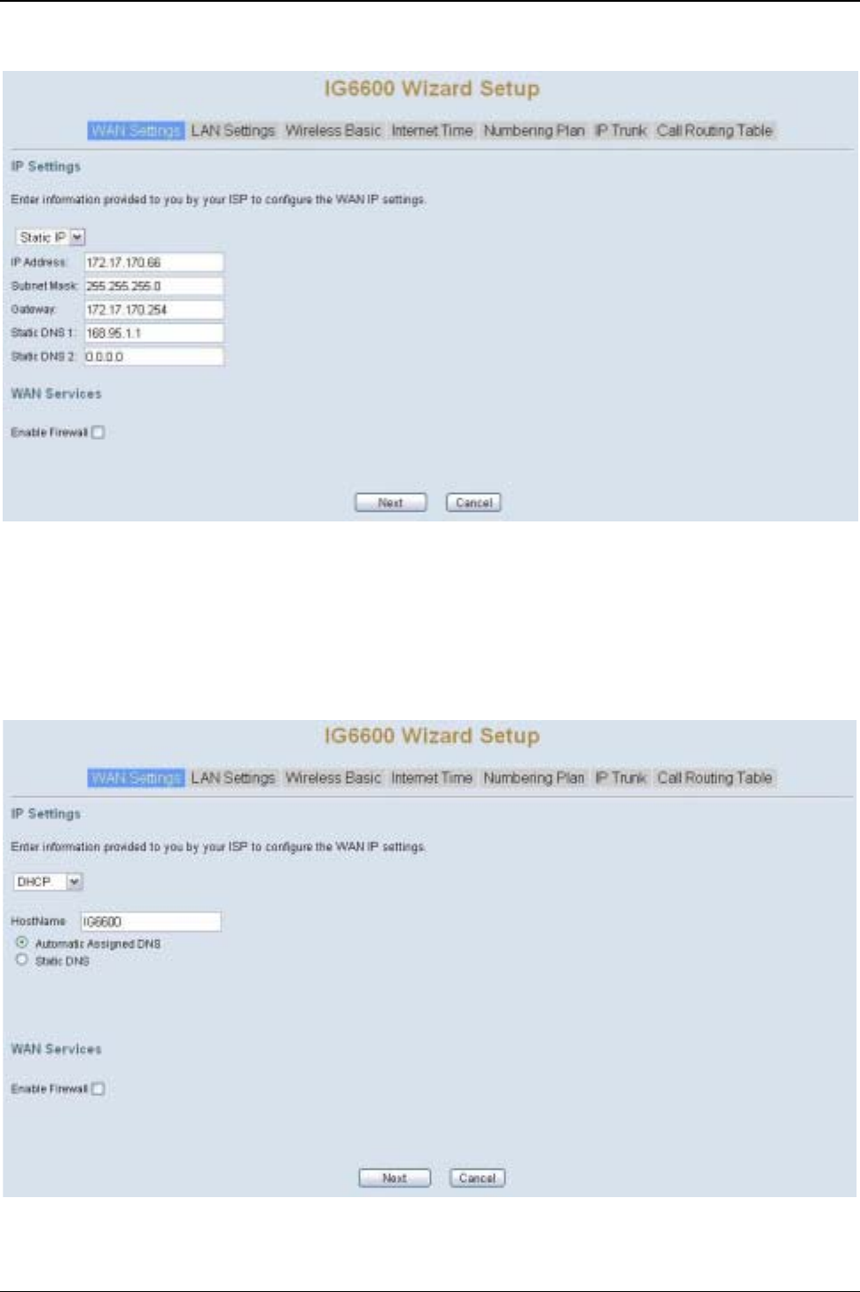
5.2.1 WAN Setting
There are three modes that you can configure WAN IP address: Static IP mode, DHCP
mode, and PPPoE mode. You can also select to enable or disable Firewall and IGMP.
Note that Network Address Translation (NAT) function is default enabled and is not
showing on the page to prevent it from being disabled.
IG6600 Administration Manual
Page 29 of 139
This page shows that the current existing WAN interface in this system is Static IP mode.
(Figure 5-1)
Figure 5-1. Wan Settings (Static IP mode)
The Dynamic Host Configuration Protocol (DHCP) is an Internet protocol for automating
the configuration of computers that use TCP/IP. DHCP can be used to automatically
assign IP addresses, to deliver TCP/IP stack configuration parameters such as the
subnet mask and default router, and to provide other configuration information.
This page shows the current existing WAN interface in this system is DHCP mode
(Figure 5-2).
Figure 5-2. Wan Settings (DHCP mode)
IG6600 Administration Manual
Page 30 of 139
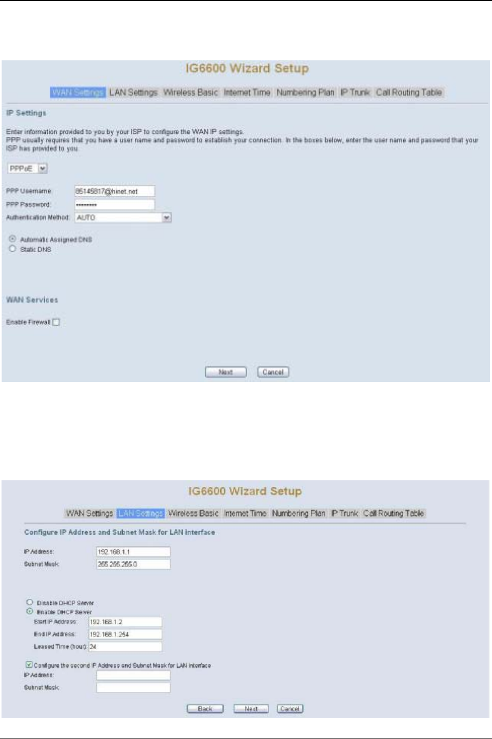
The Point-to-Point Protocol over Ethernet (PPPoE) requires a user name and password
that your ISP has provided to you to establish your connection. This page shows that the
current existing WAN interface in this system is PPPoE mode (Figure 5-3).
Figure 5-3. Wan Settings (PPPoE mode)
5.2.2 LAN Setting
This page (Figure 5-4) allows you giving LAN IP and Subnet Mask for LAN interface.
You can also select to enable or disable DHCP Server and configure related settings for
that mode.
IG6600 Administration Manual
Page 31 of 139
Figure 5-4. LAN Settings
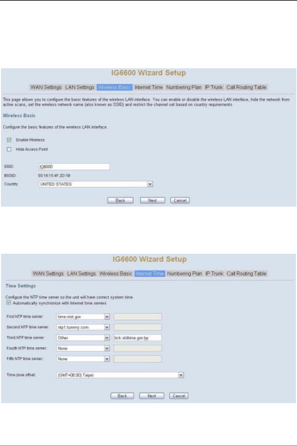
5.2.3 Wireless Basic
The page (Figure 5-5) allows you to configure basic feature of the wireless LAN
interface. You can enable or disable the wireless LAN interface, hide the network from
active scanning, set the wireless network name (also known as SSID), and restrict the
channel set based on country requirement.
Figure 5-5. Wireless Basic
5.2.4 Internet Time
The page allows you to configure the NTP time server, so the IG6600 can have correct
system time. It is useful such as reviewing the System Log. (Figure 5-6)
Figure 5-6. Internet Time

IG6600 Administration Manual
Page 32 of 139
5.2.5 Numbering Plan
IG6600 has a flexible numbering plan so that phone or trunk numbers can be
customized to meet a wild range of applications. It will check the numbers what you
enter to prevent from conflicting among the all system resources. (Figure 5-7,Figure 5-8)
Figure 5-7. Numbering Plan –1
Figure 5-8. Numbering Plan –2
IG6600 Administration Manual
Page 33 of 139
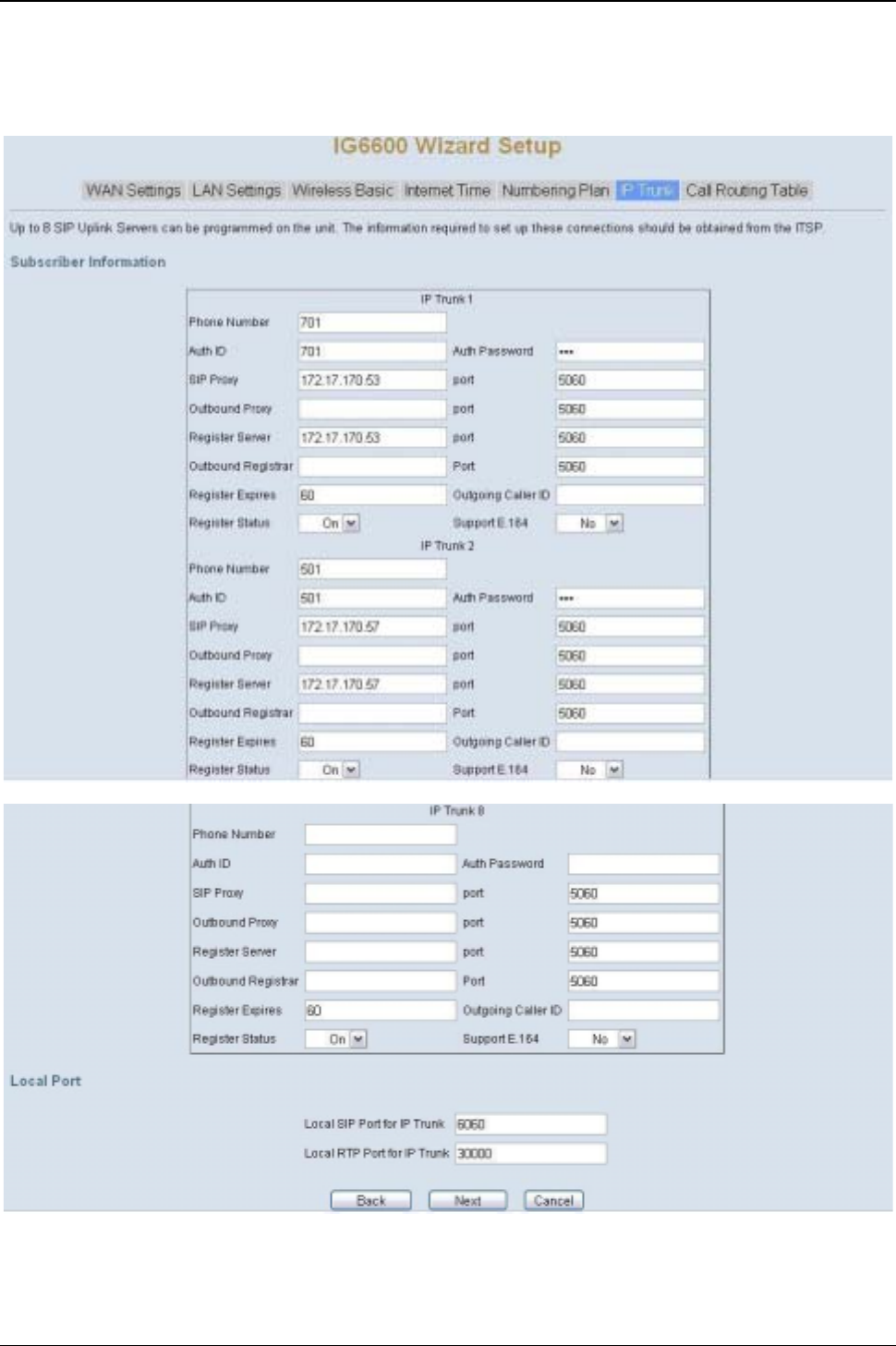
5.2.6 IP Trunk
IG6600 can register up to 8 SIP Uplink Servers. The extensions may make a call to the
users of the Uplink Servers, or any user in the world through the Uplink Servers. (Figure
5-9,Figure 5-10)
Figure 5-9. IP Trunk –1
Figure 5-10. IP Trunk –2
IG6600 Administration Manual
Page 34 of 139
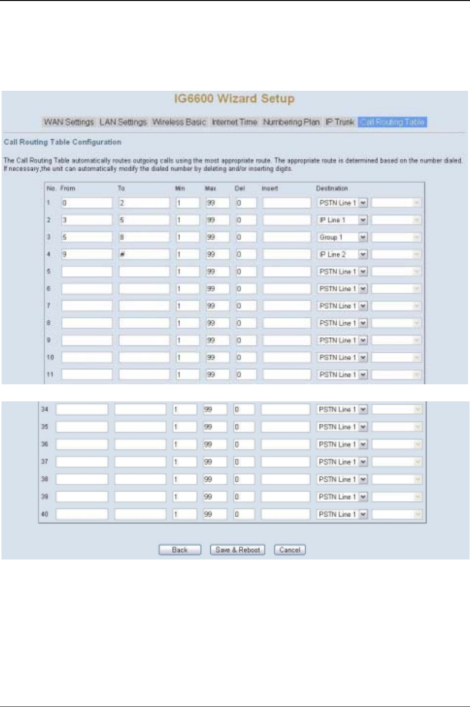
5.2.7 Call Routing Table
The Call Routing Table automatically routes outgoing calls using the most appropriate
route. The appropriate route is determined based on the number dialed. If necessary,
IG6600 can automatically modify the dialed number by deleting and/or inserting digits.
(Figure 5-11,Figure 5-12)
Figure 5-11. Call Routing Table –1
Figure 5-12. Call Routing Table –2
5.2.8 Wizard Setup Finished
When you click “Save & Reboot”Button at above page, the wizard setup will save your
setting and the wizard setup will be finished. Then the system will reboot as shown
below.

IG6600 Administration Manual
Page 35 of 139
Figure 5-13. Wizard Setup finished
Congratulations! The wizard setup of the IG6600 is complete.
For additional details, advanced configuration, or any other questions, refers to the next
chapter.
IG6600 Administration Manual
Page 36 of 139
6. Configuration
6.1 Setup
zConnect the IG6600 to PC.
zThe default LAN IP of the IG6600 is 192.168.1.1.
zThe default WAN IP of the IG6600 depends on upper router’s DHCP server.
zFor web login, the default user name is “admin1234”, the default password is
“123456”.
zFor telnet login, the name/password is the same as web login.
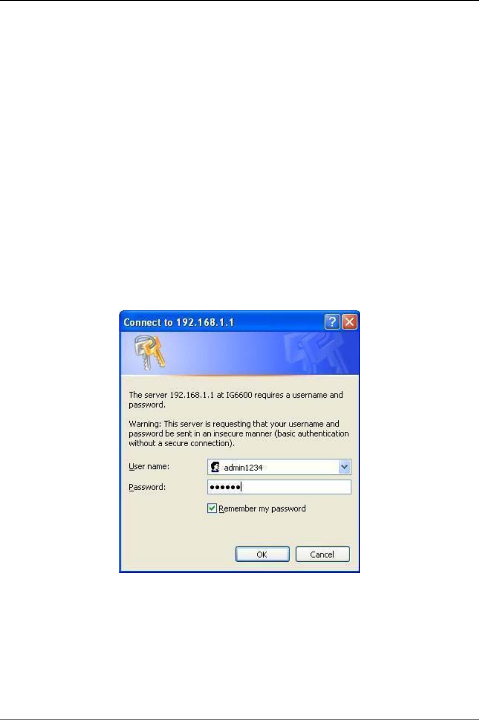
6.2 Establish The Connection
Enter the IP address of IG6600 from the Web Browser.
A Dialogue Box will pop up to request the user to enter username and password. (Figure
6-1)
Figure 6-1. Authentication
Please enter the management username/password into the fields then click the OK
button (default username/password is admin1234/123456).
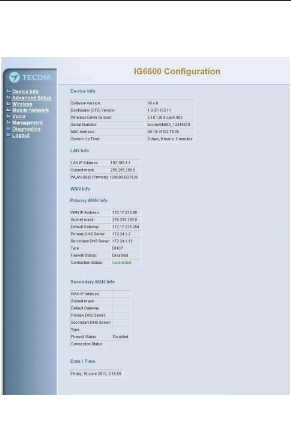
When the authentication is OK, the home page “Device Info –Summary”will be
displayed. In the Web Configuration, it is divided into seven categories (Figure 6-2):
zDevice Info
zAdvanced Setup
zWireless
IG6600 Administration Manual
Page 37 of 139
zMobile Network
zVoice
zManagement
zDiagnostics
zLogout
Figure 6-2. Device Info - Summery
IG6600 Administration Manual
Page 38 of 139
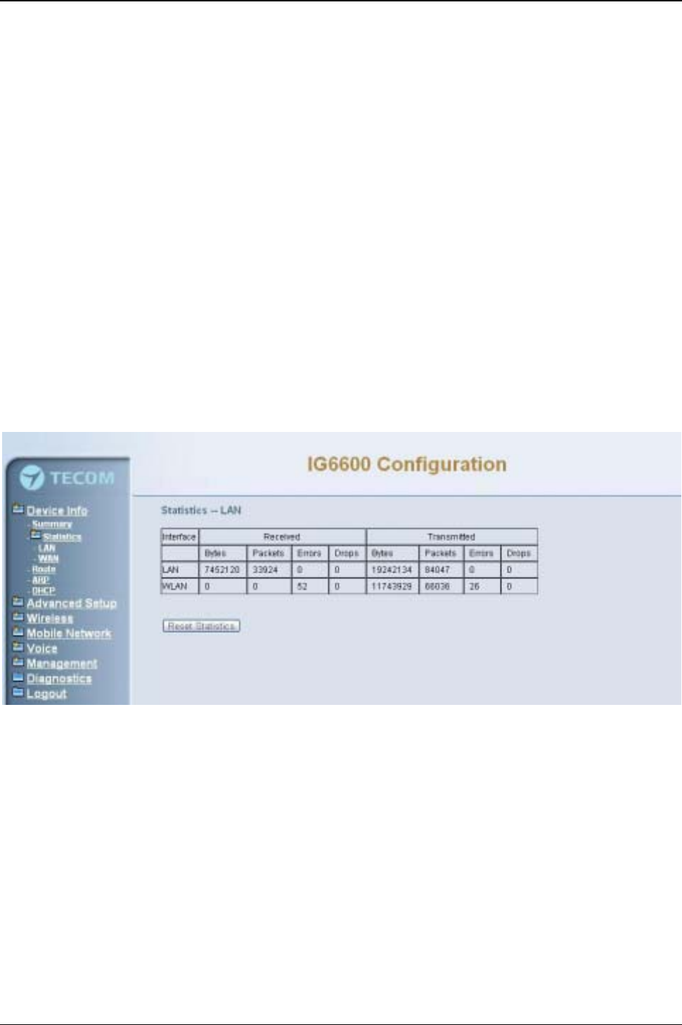
6.3 Device Info
This information reflects the current Status of IG6600 connection. It includes the
following topics:
zSummary
zStatistics
zRoute
zARP
zDHCP
6.3.1 Summary
In the page (Figure 6-2) you can get the information reflects the current software version
and connection status. It includes Device Info, Network Info and Date/Time.
6.3.2 Statistics
It’s separated into two parts: LAN and WAN.
6.3.2.1 LAN
In this page (Figure 6-3) you can get the network statistics of the LAN and Wireless LAN
interface. Click “Reset Statistics” to clean up all network statistics.
Figure 6-3. Device Info –Statistics –LAN
6.3.2.1 WAN
In this page (Figure 6-4) you can get the network statistics of the WAN interface. Click
“Reset Statistics”to clean up all network statistics.
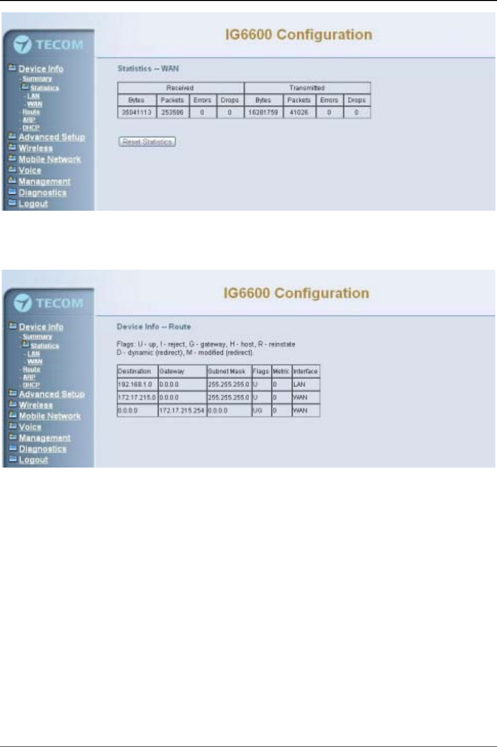
IG6600 Administration Manual
Page 39 of 139
Figure 6-4. Device Info –Statistics –WAN
6.3.3 Route
In this page you can get the IP route information of the device. (Figure 6-5)
Figure 6-5. Device Info –Route
6.3.4 ARP
This page shows an ARP table which maps IP network addresses to hardware
addresses used by data link level protocol. (Figure 6-6)
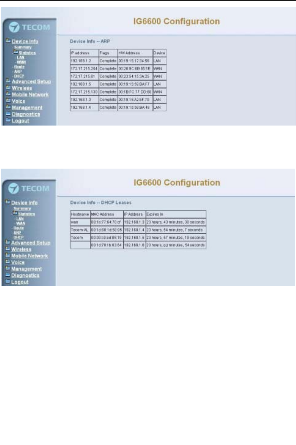
IG6600 Administration Manual
Page 40 of 139
Figure 6-6. Device Info –ARP
6.3.5 DHCP
This page shows a DHCP Leases table which shows the all used IP address under
IG6600’s DHCP Server. (Figure 6-7)
Figure 6-7. Device Info –DHCP

IG6600 Administration Manual
Page 41 of 139
6.4 Advanced
Advanced Setup allows system administrator to configure the following topics:
zWAN
zLAN
zNAT
-Virtual Servers
-Port Triggering
-DMZ Host
zSecurity
-IP Filtering
¾Outgoing
¾Incoming
zParental Control
-Time Restriction
-URL Filter
zQuality of Service
-DSCP Marking
-Bandwidth Control
zRouting
-Static Route
zDynamic DNS
zUpnp
zFile Server
zPrint Server
6.4.1 WAN
There are three modes that you can give WAN IP address to IG6600: Static IP mode,
DHCP mode and PPPoE mode. You can also enable or disable Firewall.
Network Address Translation (NAT) allows you to share one public WAN IP address for
multiple computers on your LAN side. In IG6600, NAT is default enabled and is not
shown on the page to prevent it from being disabled.
This page shows the setting of WAN interface which is Static IP mode (Figure 6-8).
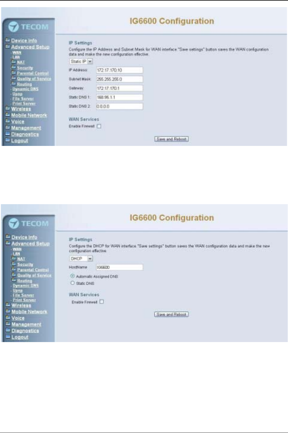
IG6600 Administration Manual
Page 42 of 139
Figure 6-8. Advanced –WAN (Static IP Mode)
The Dynamic Host Configuration Protocol (DHCP) is an Internet protocol for automating
the configuration of computers that use TCP/IP. DHCP can be used to automatically
assign IP addresses, to deliver TCP/IP stack configuration parameters such as the
subnet mask and default router, and to provide other configuration information.
This page shows the setting of WAN interface which is DHCP mode (Figure 6-9).
Figure 6-9. Advanced –WAN (DHCP Mode)
The Point-to-Point Protocol over Ethernet (PPPoE) requires a user name and password
that your ISP has provided to you to establish your connection. This page shows the
setting of WAN interface which is PPPoE mode (Figure 6-10).
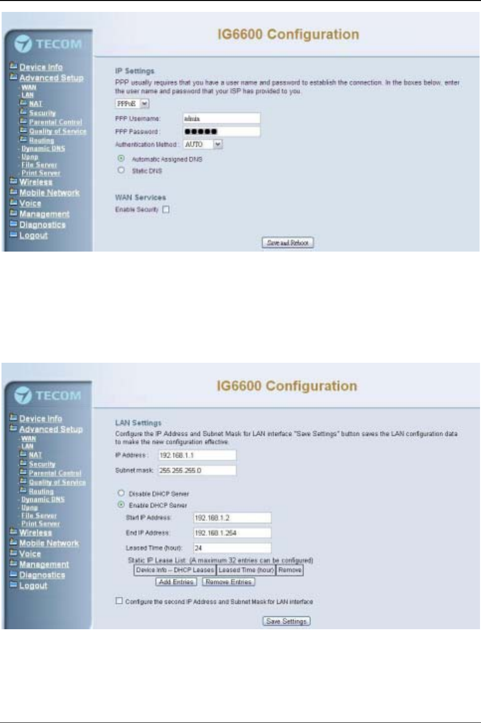
IG6600 Administration Manual
Page 43 of 139
Figure 6-10. Advanced –WAN (PPPoE Mode)
6.4.2 LAN
It allows you to set LAN IP and Subnet Mask for LAN interface. You can also enable or
disable DHCP Server and configure related settings. The “Static IP Lease List”allows to
program 32 entries to have the fixed IP address for the specified devices. If needed, it
can also configure the second IP address and Subnet Mask for the LAN interface
(Figure 6-11).
Figure 6-11. Advanced –LAN
6.4.3 NAT
It’s separated into three parts: Virtual Servers, Port Triggering, and DMZ Host.
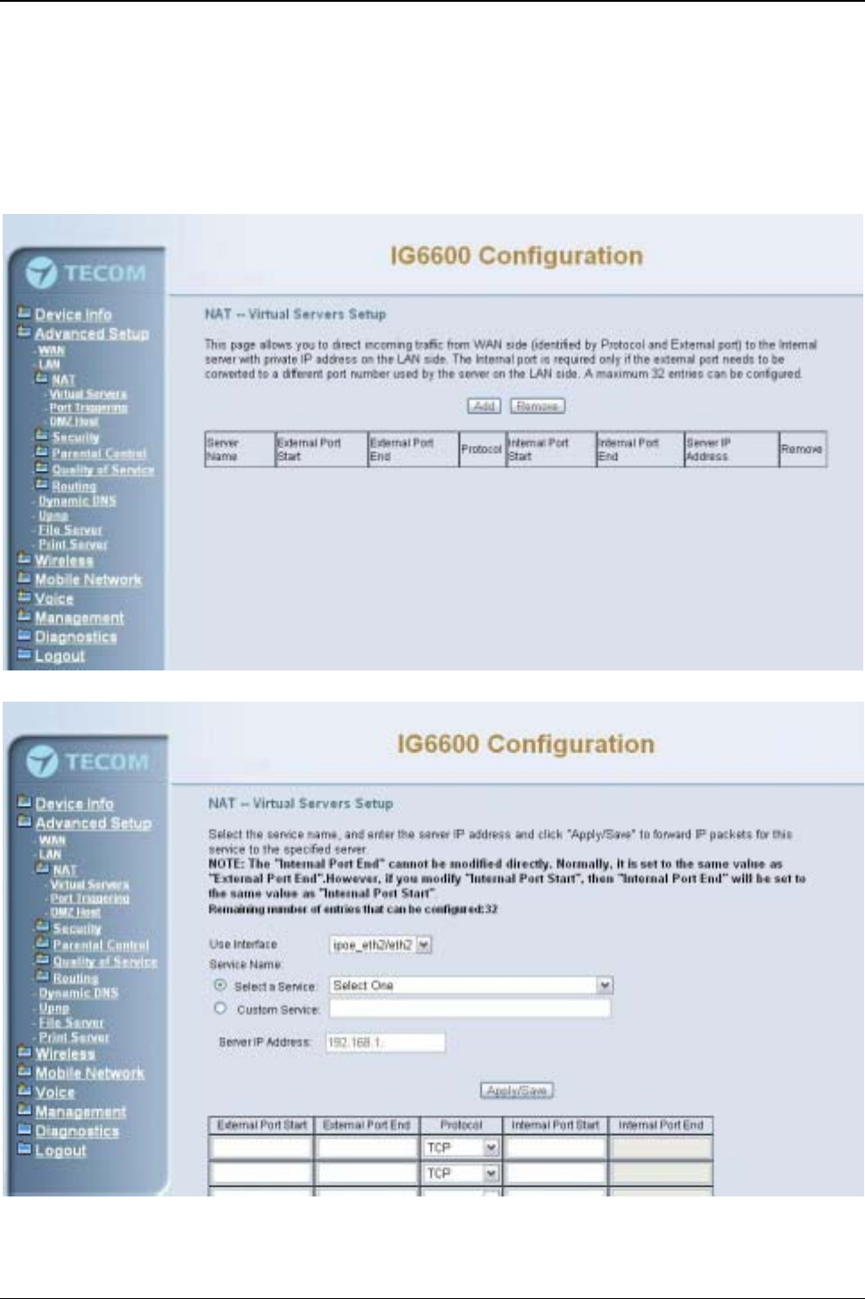
IG6600 Administration Manual
Page 44 of 139
6.4.3.1 Virtual Servers
Virtual Server allows you to direct incoming traffic from WAN side identified by Protocol
and External port to the internal server with private IP address on the LAN side. The
“Internal Port”can be modified if the “External Port”needs to be converted to a different
port number used by the server on the LAN side. The remote IP should be specified in
the table to allow the access. A maximum 32 entries can be configured. (Figure 6-12,
Figure 6-13)
Figure 6-12. Advanced –NAT –Virtual Servers
Figure 6-13. Advanced –NAT –Virtual Servers –Add
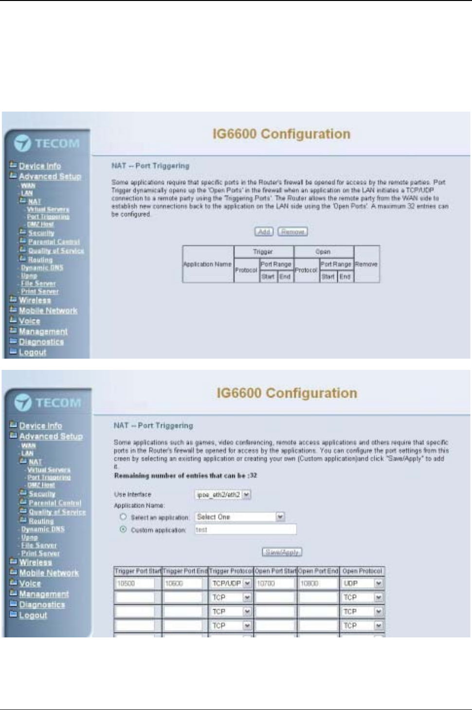
IG6600 Administration Manual
Page 45 of 139
6.4.3.2 Port Triggering
Some applications require that specific ports in the IG6600's firewall opened for access
by the remote parties. Port Triggering dynamically opens up the "Open Ports" in the
firewall when an application on the LAN initiates a TCP/UDP connection to a remote
party using the "Trigger Ports". IG6600 allows the remote party from the WAN side to
establish new connections back to the application on the LAN side using the "Open
Ports". A maximum 32 entries can be configured. (Figure 6-14,Figure 6-15)
Figure 6-14. Advanced –NAT –Port Triggering
Figure 6-15. Advanced –NAT –Port Triggering –Add
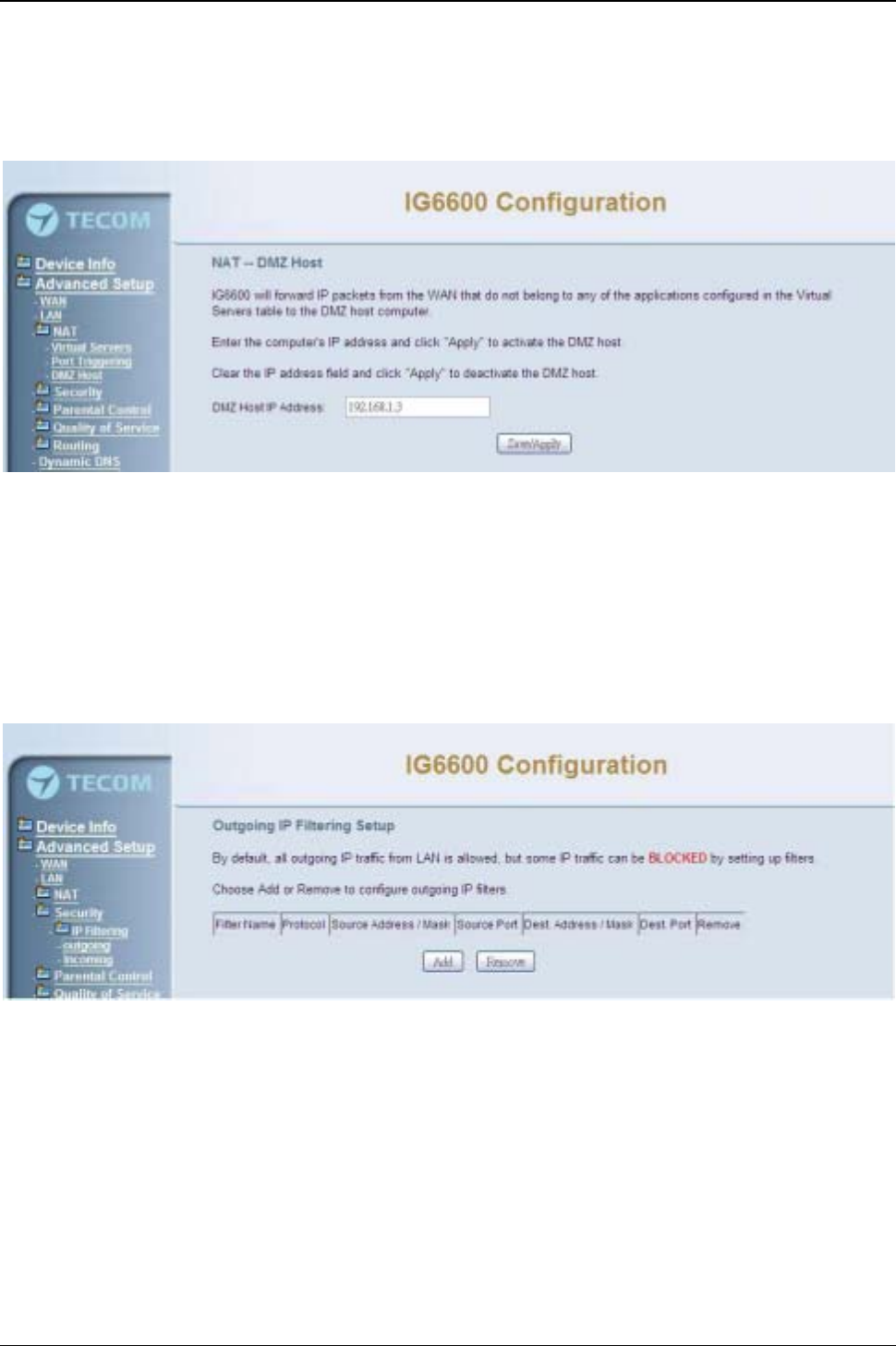
IG6600 Administration Manual
Page 46 of 139
6.4.3.3 DMZ Host
IG6600 will forward IP packets that do not belong to any of the applications configured in
the Virtual Servers table to the DMZ host computer. Enter the computer's IP address
and click "Save Settings" to activate the DMZ host. Clear the IP address field and click
"Save Settings" to deactivate the DMZ host. (Figure 6-16)
Figure 6-16. Advanced –NAT –DMZ
6.4.4 Security
It supports IP Filtering Setup. It’s separated into two parts: Outgoing and Incoming.
6.4.4.1 IP Filtering - Outgoing
It allows the administrator to create a filter rule to identify outgoing IP traffic by specifying
a new filter name. At least one condition is needed. All of the specified conditions in this
filter rule must be satisfied for the rule to take effect. (Figure 6-17,Figure 6-18)
Figure 6-17. Advanced –Security –IP Filtering – Outgoing
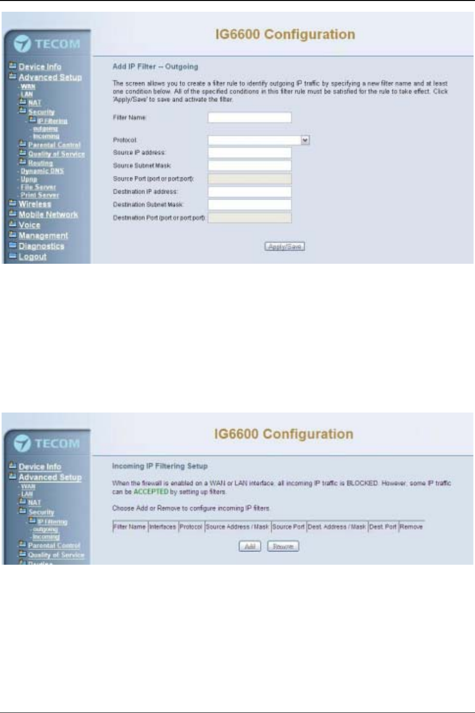
IG6600 Administration Manual
Page 47 of 139
Figure 6-18. Advanced –Security –IP Filtering – Outgoing –Add
6.4.4.2 IP Filtering - Incoming
It allows the administrator to create a filter rule to identify incoming IP traffic by
specifying a new filter name. At least one condition is needed. All of the specified
conditions in this filter rule must be satisfied for the rule to take effect. (Figure 6-19,
Figure 6-20)
By default, all incoming IP traffic from the WAN will be blocked if it is not consistent with
the incoming filter rules. In fact, IG6600 has opened some necessary ports such as web
port, sip port, and rtp port, to make sure that voice application can communicate well.
Figure 6-19. Advanced –Security –IP Filtering –Incoming
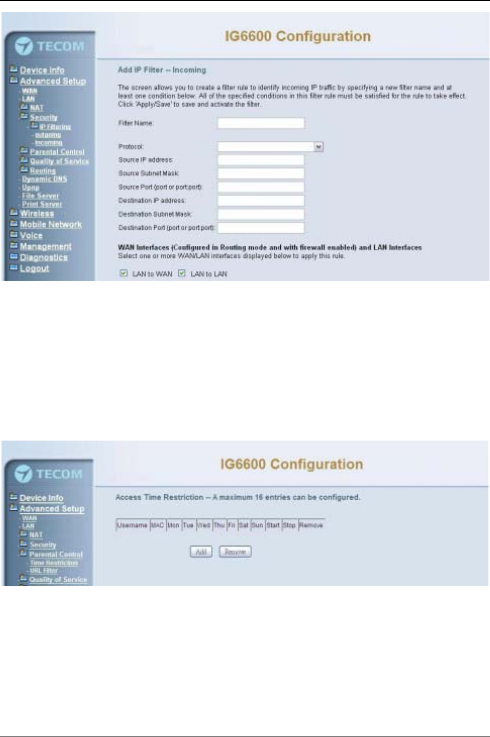
IG6600 Administration Manual
Page 48 of 139
Figure 6-20. Advanced –Security –IP Filtering –Incoming –Add
6.4.5 Parental Control
It’s separated into two parts: Time Restriction, and URL Filter.
6.4.5.1 Time Restriction
The administrator can add time restriction to a special LAN device connected to IG6600.
The “Browser's MAC Address”automatically displays the MAC address of the LAN
device where the browser is running. To restrict other LAN device, click the "Other MAC
Address" button and enter the MAC address of the other LAN device. (Figure 6-21,
Figure 6-22)
Figure 6-21. Advanced –Parental Control –Time Restriction
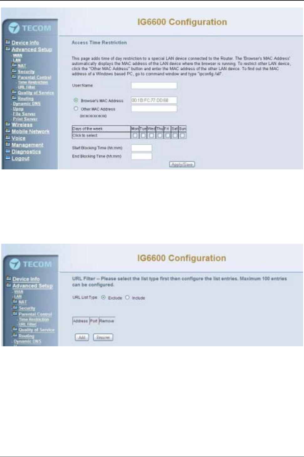
IG6600 Administration Manual
Page 49 of 139
Figure 6-22. Advanced –Parental Control –Time Restriction –Add
6.4.5.1 URL Filter
The administrator can add 100 entries maximum to include/exclude the URL address
and Port number. Choose “Include”means the user can only connect to the URL that
you add. Choose “Exclude”means the user can not connect to the URL that you add.
“Include”and “Exclude”are exclusive. The all entries are for the selected type. (Figure
6-23,Figure 6-24).
Figure 6-23. Advanced –Parental Control –URL Filter
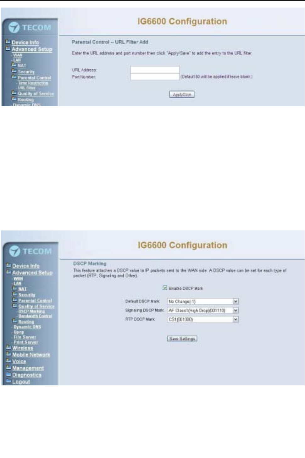
IG6600 Administration Manual
Page 50 of 139
Figure 6-24. Advanced –Parental Control –URL Filter –Add
6.4.6 Quality of Service
It’s separated into two parts: DSCP Marking, and Bandwidth Control
6.4.6.1 DSCP Marking
IP QoS is applied to the traffic from LAN to WAN; the traffic from WAN to LAN will not be
applied.(Figure 6-25)
If "Enable DSCP Mark”checkbox is selected, choose a default DSCP mark to
automatically mark incoming traffic without reference to a particular classifier. Click
"Save Settings" button to save it. Note: If "Enable DSCP Mark”checkbox is not selected,
all QoS will be disabled for all interfaces. The default DSCP mark is used to mark all
egress packets.
Figure 6-25. Advanced – Quality of Service –DSCP Marking
6.4.6.2 Bandwidth Control
Bandwidth Control allows you to control WAN port's upstream bandwidth according to
your settings, and it can ensure the highest priority IP packet traffic throughput. By
default, all voice packets have been queued in the highest IP packets, and the others
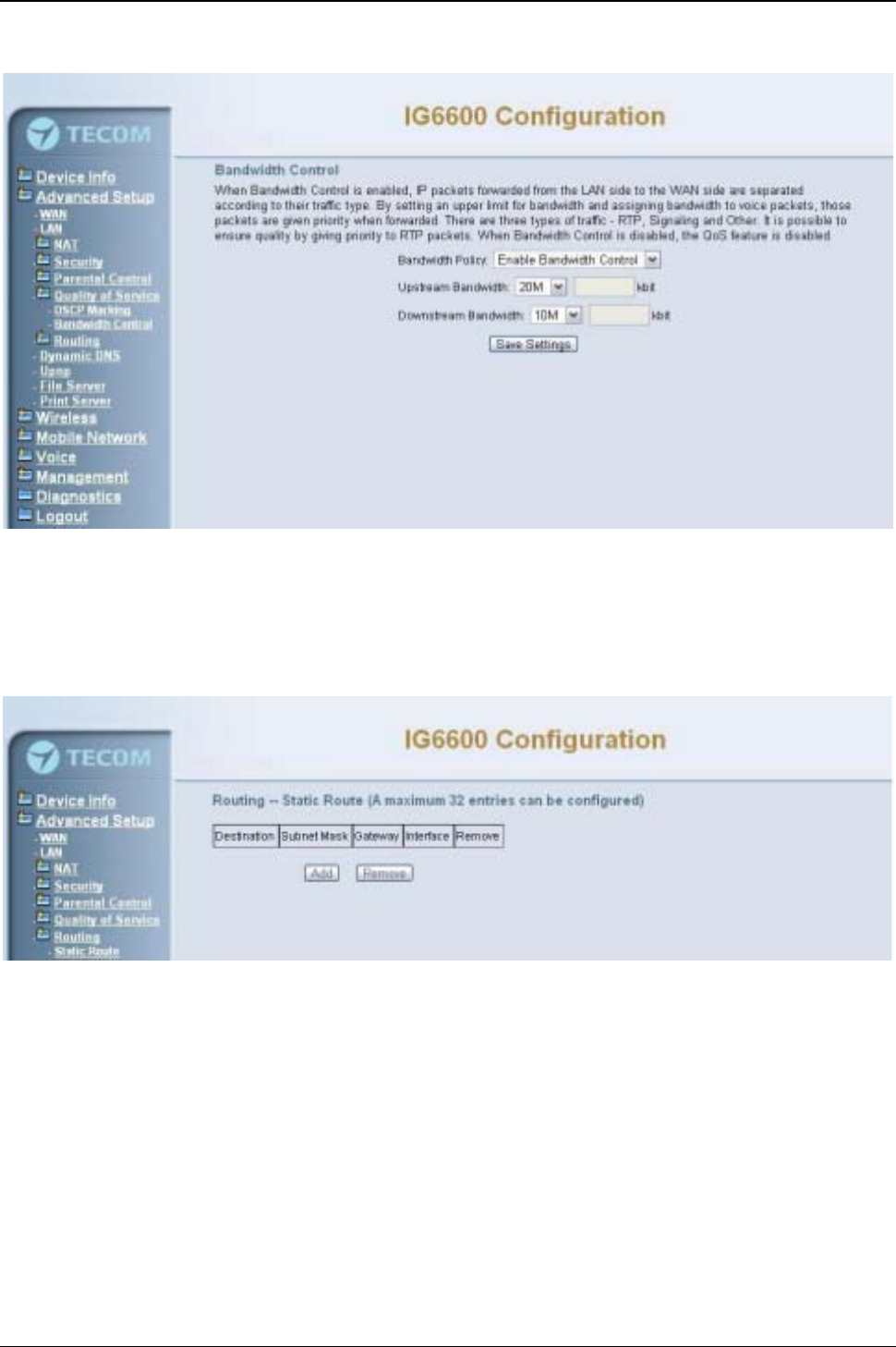
IG6600 Administration Manual
Page 51 of 139
have been queued in the normal IP packets if they have not been set in the traffic class
rule.
Figure 6-26. Advanced – Quality of Service –Bandwidth Control
6.4.7 Routing
6.4.7.1 Static Route
The Static Route allows you to add special routing rules into routing table.
Figure 6-27. Advanced –Route –Static Route
Click “Add” to create a new Static Route. Enter the destination network address, subnet
mask, gateway AND/OR available WAN interface then click "Save Settings" to add the
entry to the routing table. (Figure 6-27,Figure 6-28)
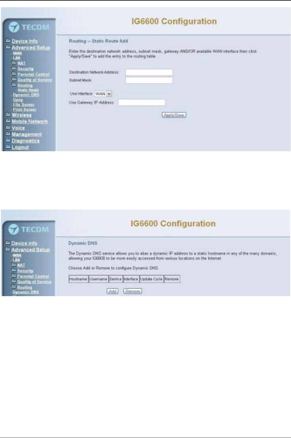
IG6600 Administration Manual
Page 52 of 139
Figure 6-28. Advanced –Route –Static Route –Add
6.4.8 Dynamic DNS
The Dynamic DNS service allows you to alias a register domain name to a dynamic IP
address. It allows IG6600 to be more easily accessed from various locations on the
Internet. Click “Add”or “Remove” to configure Dynamic DNS. (Figure 6-29)
Figure 6-29. Advanced –Dynamic DNS
Now IG6600 support for two DDNS provider, DynDNS.org and TZO. Specify the register
hostname and choose the related interface. Fill in the username/password or email/key
and click “Apply/Save”. IG6600 will update the current IP with DDNS provider when click
“Apply/Save”or system reboot successfully. IG6600 will also update the current IP
automatically with DDNS provider in the programmed Update Cycle. (Figure 6-30,Figure
6-31)
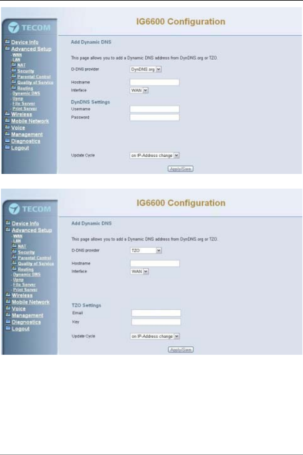
IG6600 Administration Manual
Page 53 of 139
Figure 6-30. Advanced –Dynamic DNS –DynDNS.org
Figure 6-31. Advanced –Dynamic DNS –TZO
6.4.9 Upnp
It’s used to enable or disable the universal plug and play function. (Figure 6-32)
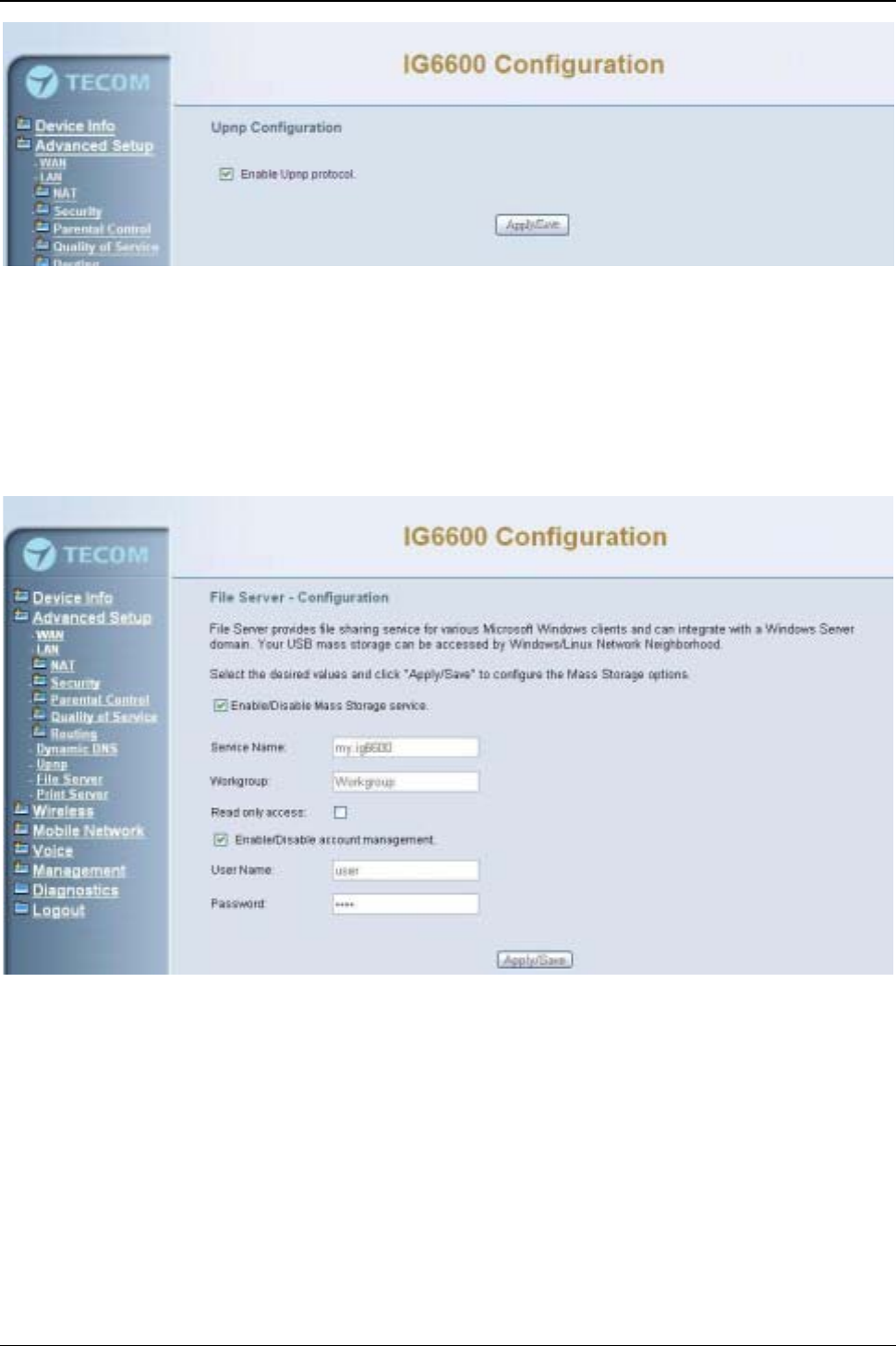
IG6600 Administration Manual
Page 54 of 139
Figure 6-32. Advanced –Upnp
6.4.10 File Server
IG6600 provides file sharing service for various Microsoft Windows clients. Your USB
mass storage can plug into the IG6600 USB port and can be accessed by
Windows/Linux Network Neighborhood (Figure 6-33).
Note: Currently IG6600 only supports the USB Storage device with one partition, the
device with multiple partitions may have problem to be recognized and used.
Figure 6-33. Advanced –File Server
Enter the service name and Workgroup. The “Workgroup”is the name of the group that
shares the same resources on the local network. The workgroup name of windows
system user must the same with the IG6600 workgroup. You can check your workgroup
by the following step:
1. Open the Control Panel from the Start menu and click on the “System”icon.
2. Open the “System Properties”window.
3. Click the “Computer Name” tab. It will show details of the computer's description,
name and workgroup.(Figure 6-34)
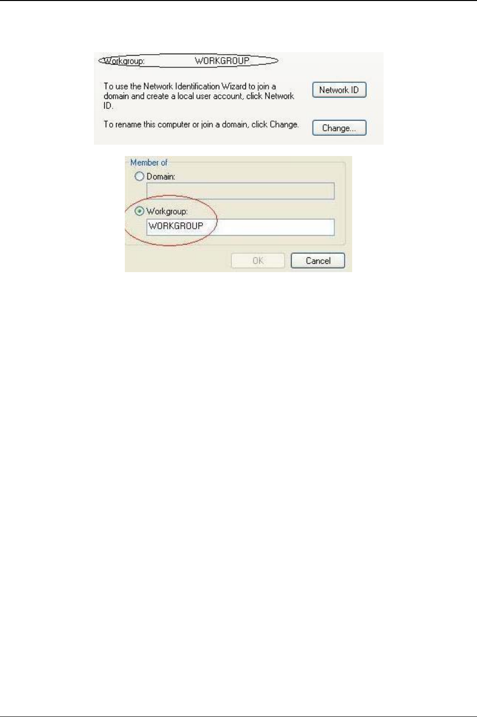
IG6600 Administration Manual
Page 55 of 139
4. If workgroup name is different from IG6600 workgroup name, you can click “Change”
to revise workgroup name of your computer or just change IG6600 workgroup
name.(Figure 6-35)
Figure 6-34. Windows workgroup
Figure 6-35. Change windows system workgroup
User can use search function in windows to connect to IG6600 file server:
1. Click “Search”in the windows “Start menu”.
2. Click “Computers and People”and input IG6600 Service Name. Click “Search”.
(Figure 6-36)
3. The window will show IG6600 file server icon. Click the icon. (Figure 6-36)
4. Enter the user name and password that you register in the IG6600 file server. Then
you will see the sharing files of your account. (Figure 6-37)(Figure 6-38)
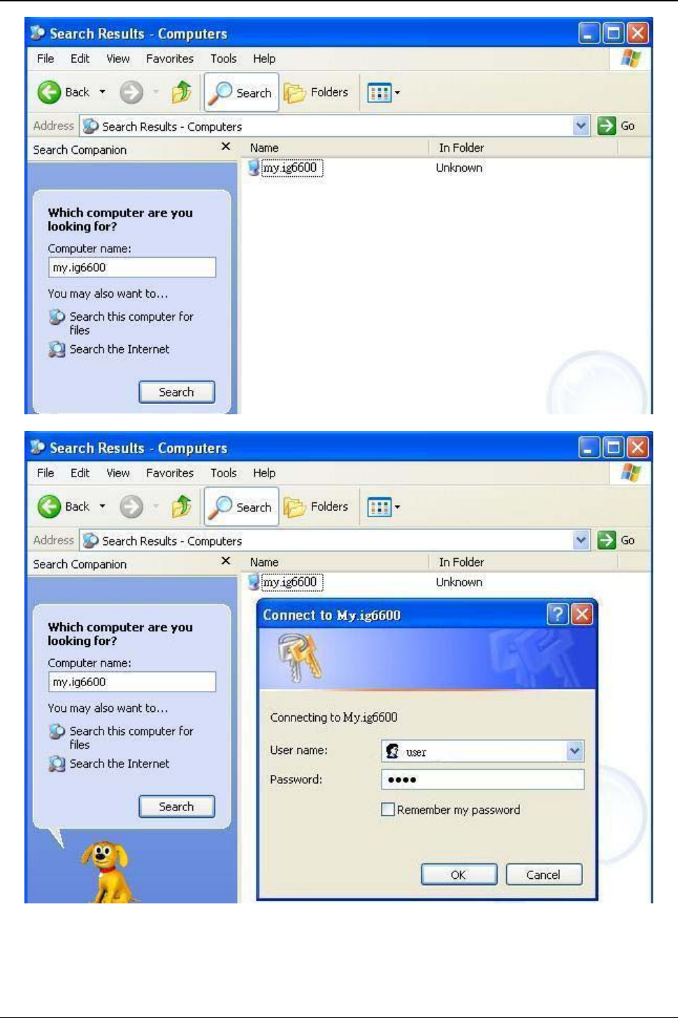
IG6600 Administration Manual
Page 56 of 139
Figure 6-36. Search ig6600 file server
Figure 6-37. Input file server username and password
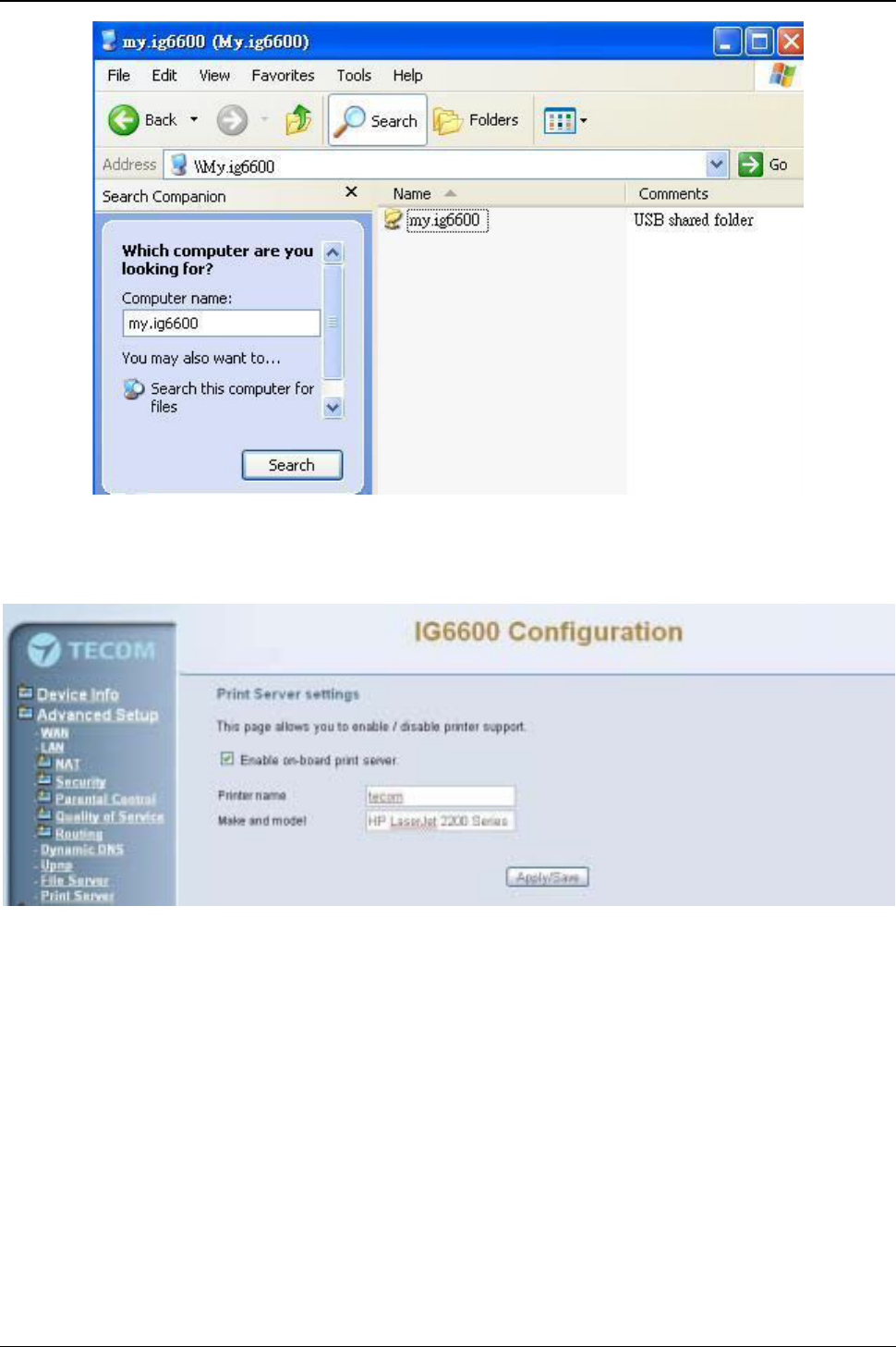
IG6600 Administration Manual
Page 57 of 139
Figure 6-38. USB Sharing files
6.4.11 Print Server
IG6600 has a USB Interface. It allows connecting a USB printer. The page is to program
the Printer setting. (Figure 6-39)
Figure 6-39. Advanced –Print Server
Enter the Printer name. The printer name will be used by user to access the printer. “Make
and model”is the model name of the printer. User can access the USB printer by the
following step:
1. Open the Printers and Faxes Window in windows system control panel.
2. Select the Add New Printer link. The add printer wizard window will be
displayed.(Figure 6-40)
3. Select Next on the Add New Printer Wizard Screen. Select “A network printer, or a
printer attached to another computer.”Then press the Next button.(Figure 6-41)
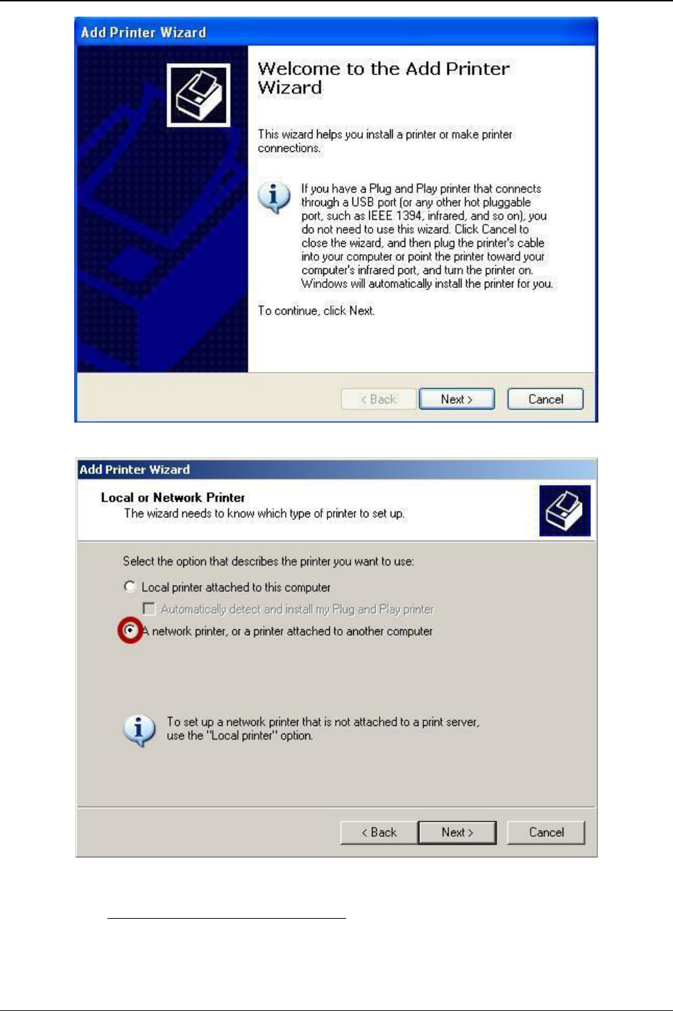
IG6600 Administration Manual
Page 58 of 139
Figure 6-40. Add Printer Wizard
Figure 6-41. Local or Network Printer
4. Select “Connect to a printer on the Internet or on a home or office network”and Input
the URL:”http://192.168.1.1/printers/tecom”. The 192.168.1.1 in the URL is your
IG6600 LAN IP address. The “tecom”in the URL is the Printer name.(Figure 6-42)
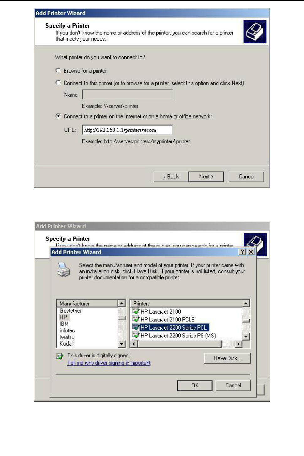
IG6600 Administration Manual
Page 59 of 139
Figure 6-42. Specify a Printer
5. Select the Manufacturer and model of your printer. Press OK.(Figure 6-43)
Figure 6-43. Select Printer Manufacturer and Model
6. The setup is completed.(Figure 6-44)
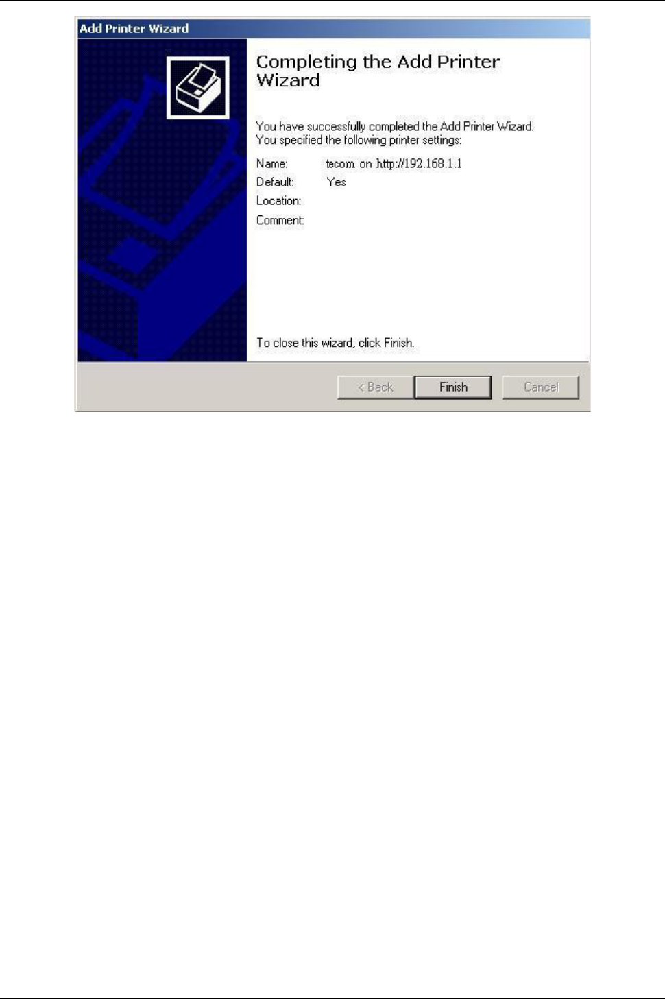
IG6600 Administration Manual
Page 60 of 139
Figure 6-44. Completing the Add Printer Wizard
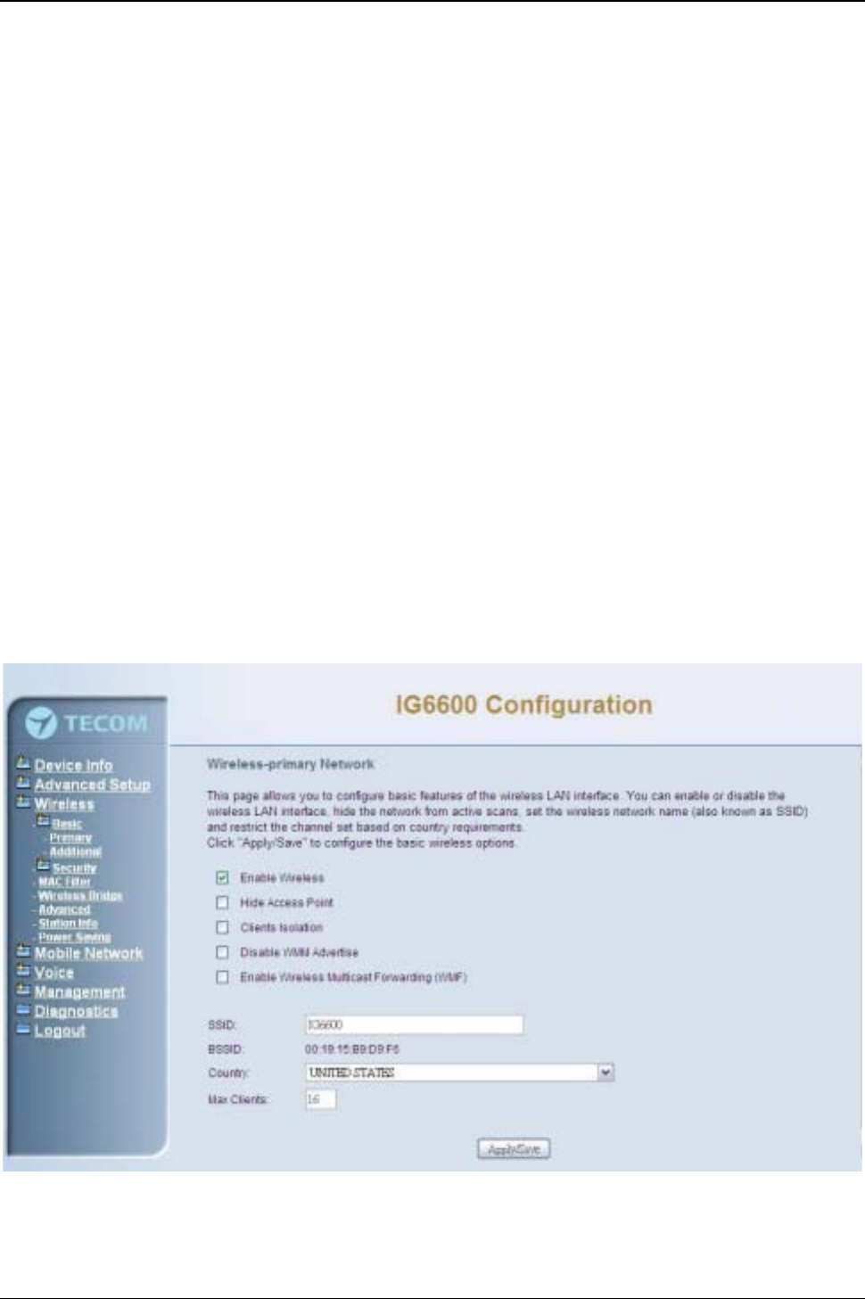
IG6600 Administration Manual
Page 61 of 139
6.5 Wireless
Use the Wireless screen to configure the IG6600 for wireless access. It is separated into
7 parts:
zBasic
-Primary
- Additional
zSecurity
zMAC Filter
zWireless Bridge
zAdvanced
zStation Info
zPower Saving
The configurable items for each part would be described in the following.
6.5.1 Basic
It’s separated into two parts: Primary, and Additional.
6.5.1.1 Primary
This page allows you to configure the basic features of the wireless LAN interface. You
can enable or disable the wireless LAN interface, hide the network from active scans,
active the client isolation, disable WMM advertise and enable wireless multicast
forwarding.
User can set the wireless network name (also known as SSID) and restrict the channel
set based on country requirements. The max clients are 16. (Figure 6-45)
Figure 6-45. Wireless –Basic –Primary
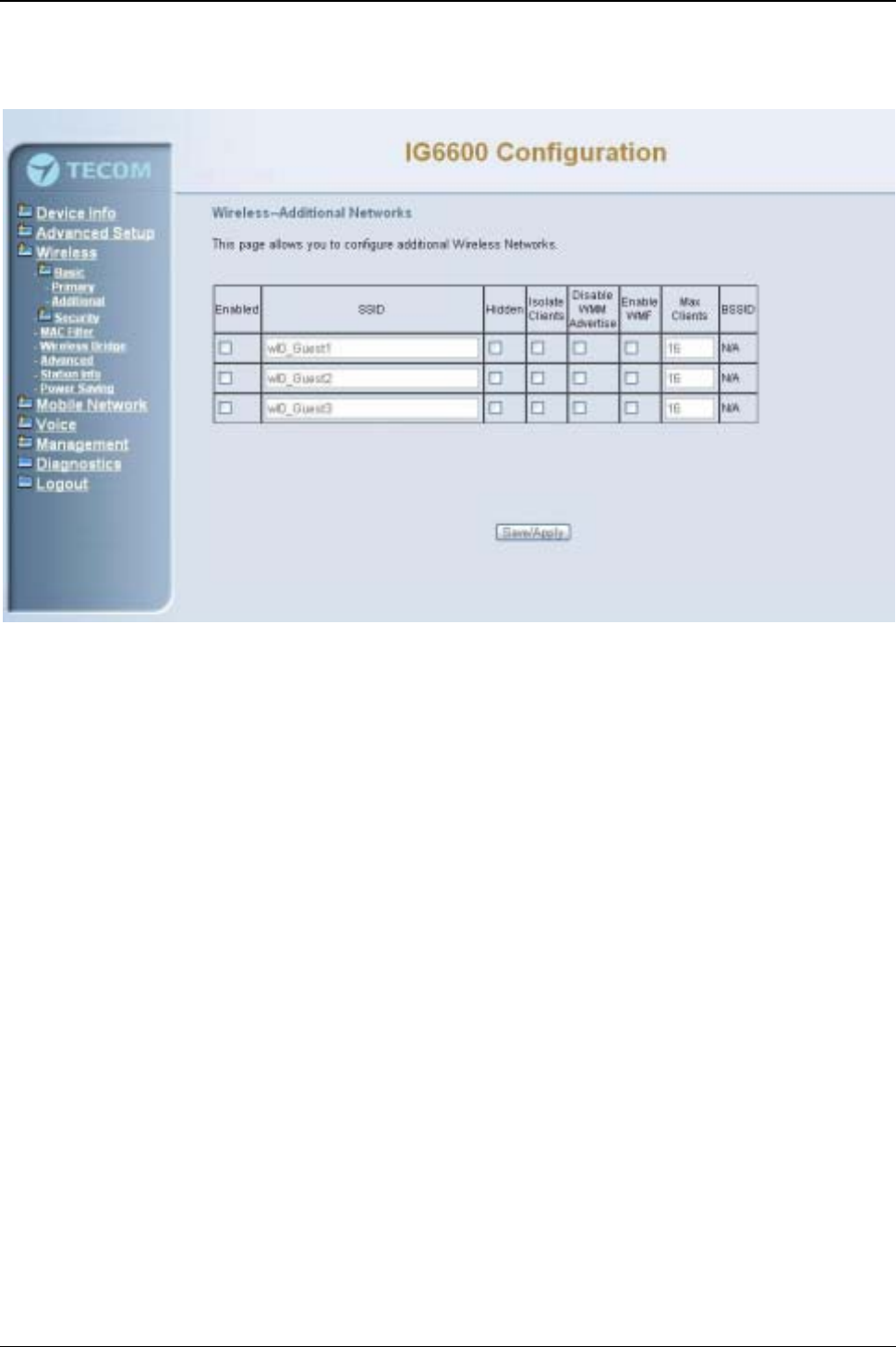
IG6600 Administration Manual
Page 62 of 139
6.5.1.1 Additional
IG6600 supports to configure 3 additional Wireless networks. Each SSID can have
different name and configurations. (Figure 6-46)
Figure 6-46. Wireless –Basic –Additional
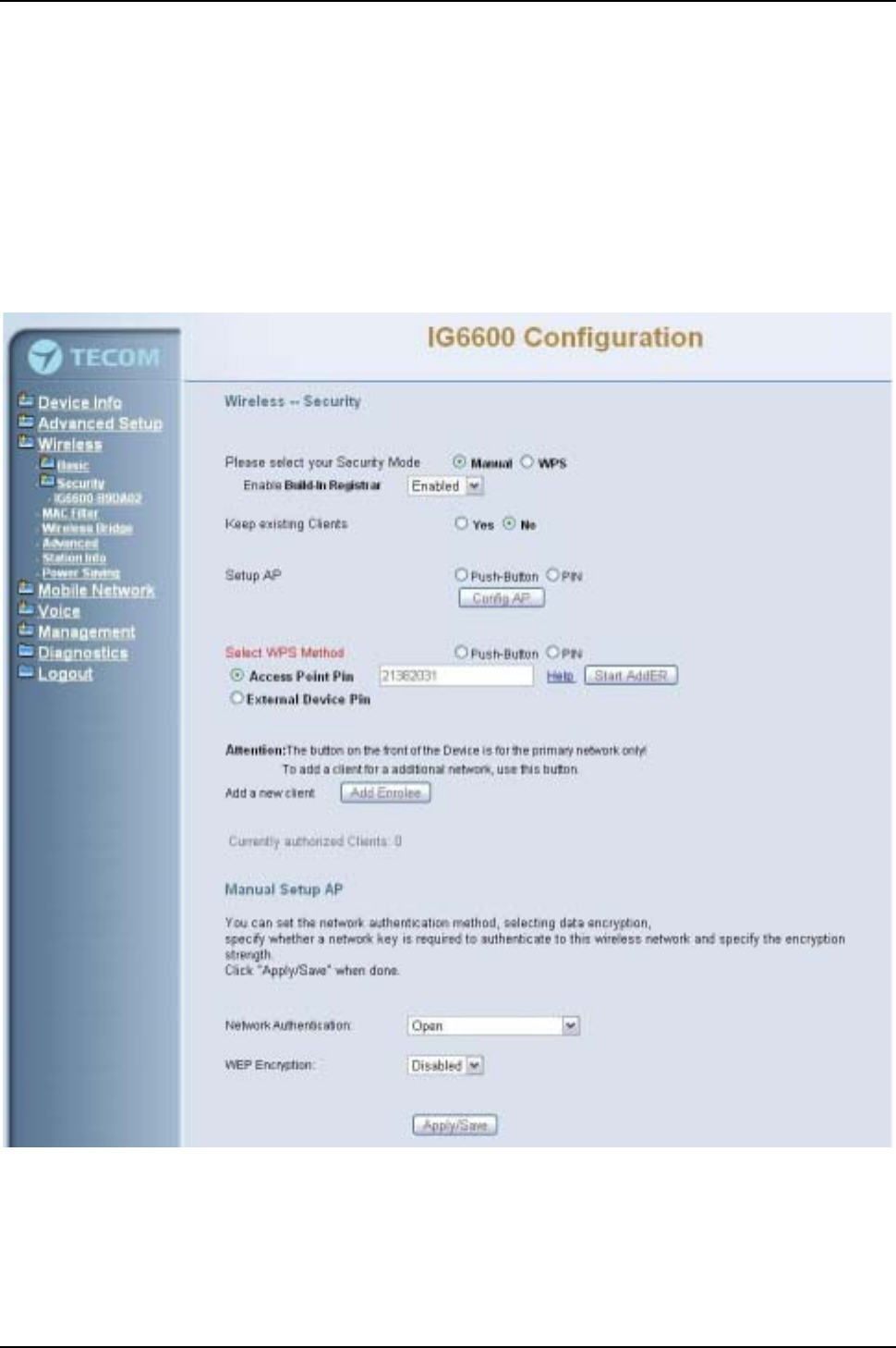
IG6600 Administration Manual
Page 63 of 139
6.5.2 Security
This page allows you to configure security features of the wireless LAN interface. It
allows you to select your Security Mode: Manual and WPS.
In WPS mode, it follows the Wi-Fi Protected Setup standard for easy and secure
wireless network set up and connection. User can use Push-Button or PIN to configure
the connection with IG6600. In Push-Button method, IG6600 and client must press the
WPS button to establish connection. In PIN mode, when the Access Point Pin is used,
client can input the PIN to establish the connection. When the External Device PIN is
used, client device PIN can be entered in the field to establish connection (Figure 6-47).
Figure 6-47. Wireless –Basic –Additional
In Manual mode, you can set the network authentication method, selecting data
encryption, specify whether a network key is required to authenticate to this wireless
network and specify the encryption strength. Click "Apply/Save" to configure the wireless
security options. (Figure 6-48,Figure 6-49)
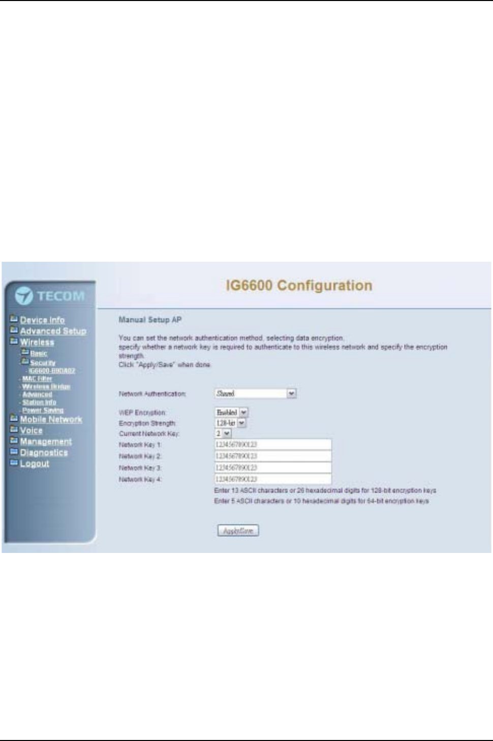
IG6600 Administration Manual
Page 64 of 139
The following items will be configured in the page:
Network Authentication: Set the network Authentication method. Open and Shared
can use the WEP Encryption. 802.1X and WPA require setting valid RADIUS
parameters. WPA-PSK requires a valid WPA Pre-Shared Key to be set.
802.1X: As the IEEE standard for access control for wireless and wired LANs, 802.1x
provides a means of authentication and authorizing devices to attach to a LAN port.
This standard defines the Extensible Authentication Protocol (EAP), which uses a
central authentication server to authenticate each user on the network.
WPA/WPA2: The Wi-Fi Alliance put together WPA/WPA2 as a data encryption
method for 802.11 wireless LANs. WPA is an industry-supported, pre-standard
version of 802.11i utilizing the Tempoal Key Integrity Protocol (TKIP), which fixes the
problems of WEP, including using dynamic keys.
WPA/WPA2 Pre-Shared Key: Set the WPA/WPA2 Pre-Shared Key (PSK).
WPA/WPA2 Group Rekey Interval: Set the WPA/WPA2 Group Rekey Interval in
seconds. Leave blank or set to zero to disable periodic re-keying.
Figure 6-48. Wireless –Security –1
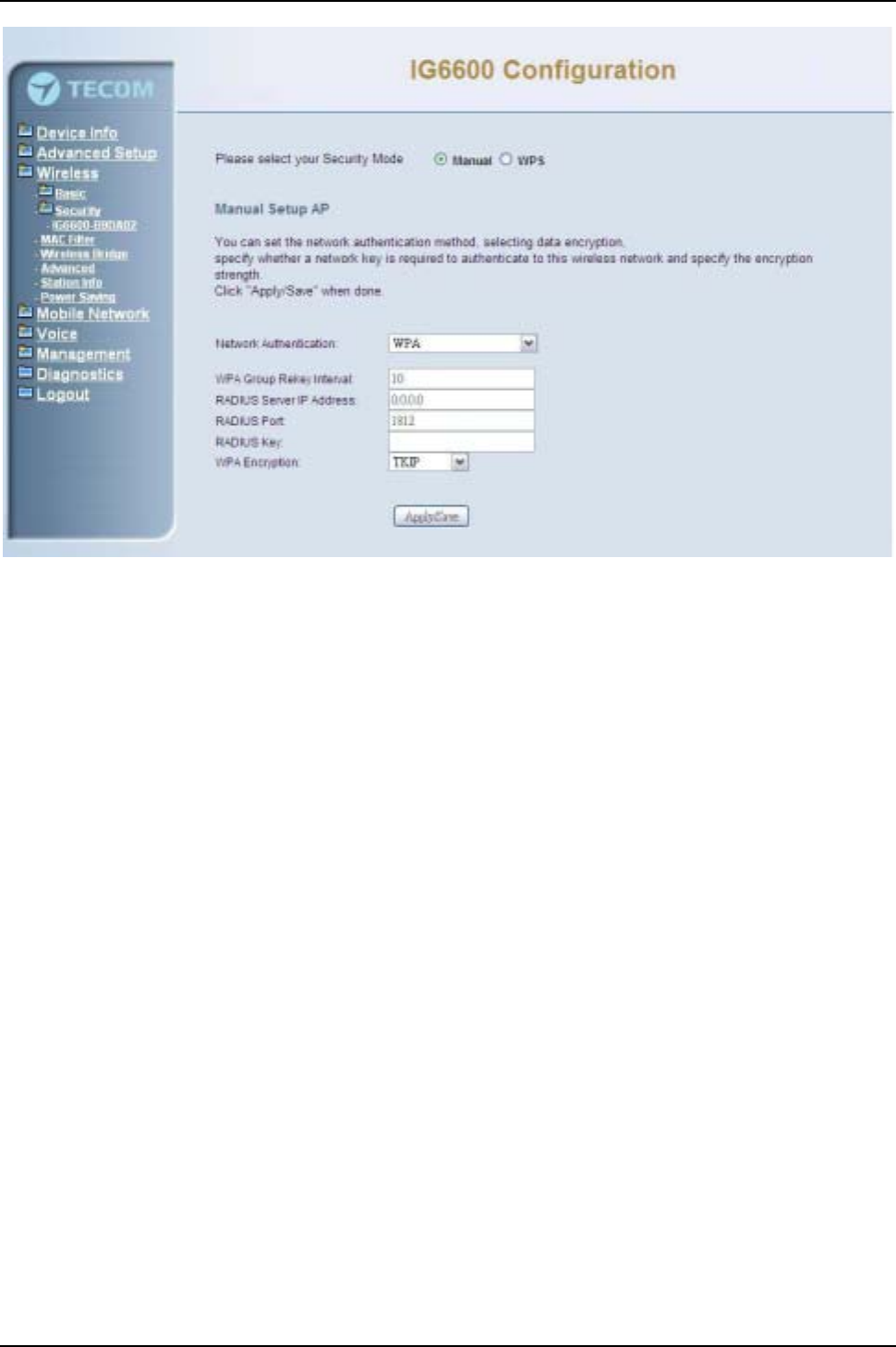
IG6600 Administration Manual
Page 65 of 139
Figure 6-49. Wireless –Security –2
Radius Server: Set the IP address of the RADIUS server to use for authentication
and dynamic key derivation.
RADIUS Server is responsible for receiving user connection requests, authenticating
the user, and then returning all of the configuration information necessary for the
client to deliver the server to the user.
Radius Port: Sets the UDP port number of the RADIUS server. The port number is
usually 1812 or 1645 and depends on the server.
Radius Key: Set the shared secret for the RADIUS connection.
WEP Encryption: Selecting Disabled disables WEP data encryption. Selecting
Enabled enables WEP data encryption and requires that a valid network key be set
and selected unless 802.1X is enabled.
WEP, short for Wired Equivalent Privacy, is a protocol for wireless LANs or local area
networks. This WEP is defined in the 802.11 Standard. WEP is designed so security
levels are maintained at the same level as the wired LAN. WEP’s aim is to provide
security by encrypting data over radio waves. WEP protects data as it’s transmitted
from one end point to another. WEP is used at two lowest layers, the data link and
physical layer. WEP is designed to make up for the inherent security in wireless
transmission as compared to wired transmission.
Network Key: Set whether shared key authentication is required to associate. A valid
network key must be set and selected if required.
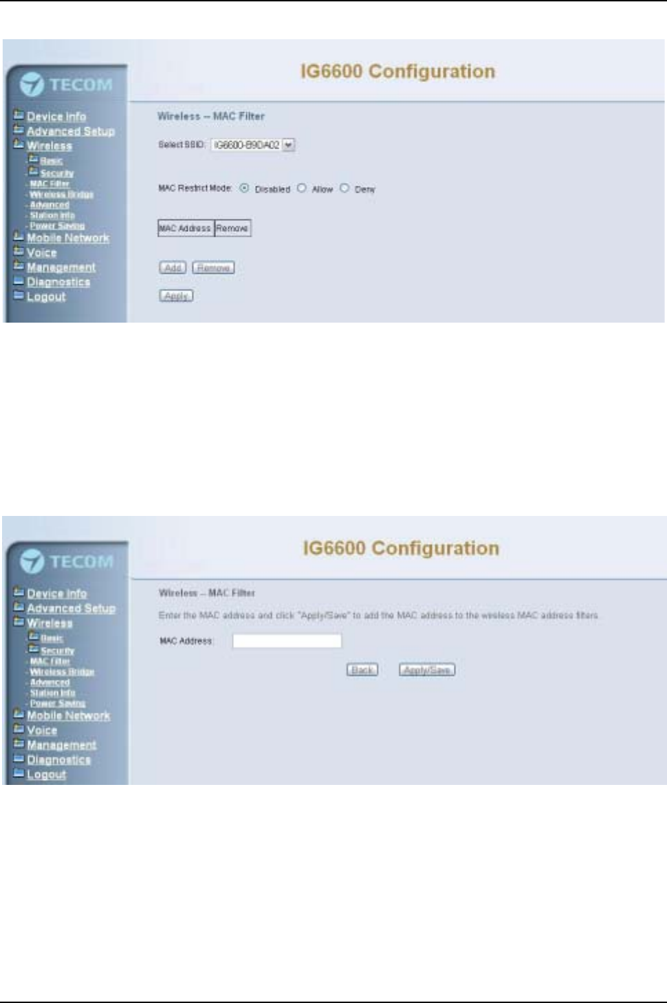
IG6600 Administration Manual
Page 66 of 139
6.5.3 MAC Filter
Figure 6-50. Wireless –MAC Filter
This page allows users to Add/Remove hosts with the specified MAC addresses that are
able or unable to access the wireless network. When users decide to use Allow, only the
MAC addressed in the user-defined list can access the wireless network. When users
use Deny, only the user specified MAC addresses are unable to access to wireless
network. And if the Disable option is selected, all users will be able to access to wireless
network.
Note: The MAC addresses in the list would immediately take effect when Allow or Deny
is checked. (Figure 6-50,Figure 6-51)
Figure 6-51. Wireless –MAC Filter –Allow/Deny
6.5.4 Wireless Bridge
This page allows you to configure wireless bridge features of the wireless LAN interface.
You can select Wireless Bridge (also known as Wireless Distribution System) to connect
to other wireless bridge device, but the access point functionality will be disabled.
Selecting Access Point enables access point functionality. Wireless bridge functionality
will still be available and wireless stations will be able to associate to the AP. Select
Disabled in Bridge Restrict which disables wireless bridge restriction. Any wireless
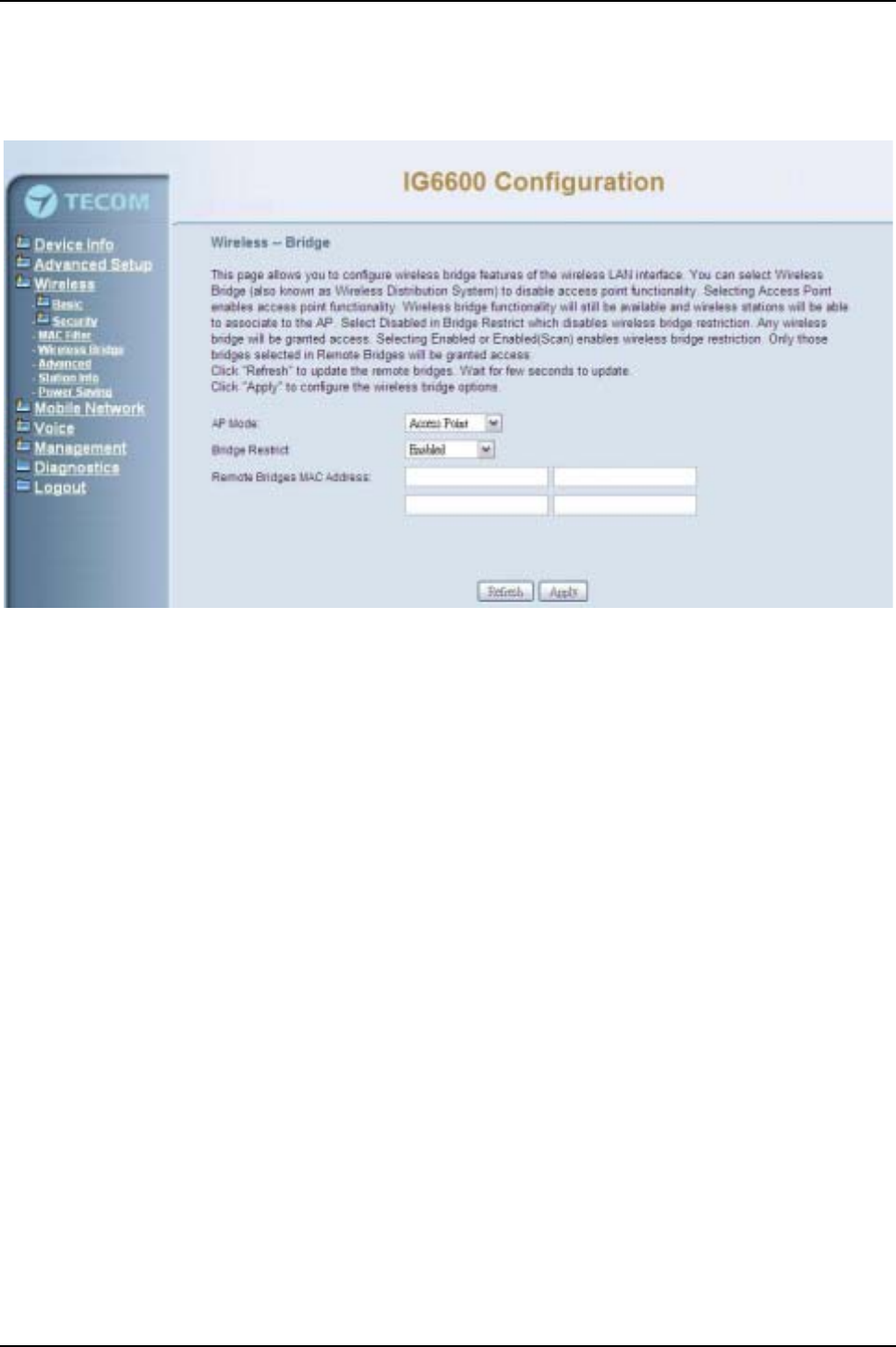
IG6600 Administration Manual
Page 67 of 139
bridge will be granted access. Selecting Enabled or Enabled (Scan) enables wireless
bridge restriction. Only those bridges selected in Remote Bridges will be granted access.
Click "Refresh" to update the remote bridges. Wait for few seconds to update. Click
"Save Settings" to configure the wireless bridge options. (Figure 6-52)
Figure 6-52. Wireless –Wireless Bridge
6.5.5 Advanced
It allows you to configure advanced features of the wireless LAN interface. You can
select a particular channel on which to operate, force the transmission rate to a
particular speed, set the fragmentation threshold, set the RTS threshold, set the wakeup
interval for clients in power-save mode, set the beacon interval for the access point, set
XPress mode and set whether short or long preambles are used. Click "Save Settings"
to configure the advanced wireless options. (Figure 6-53,Figure 6-54)
Band: Default setting is 2.4GHz.
Channel: Select the appropriate channel from the list provided to correspond with
your network settings. All devices in your wireless network must use the same
channel in order to function correctly.
Auto Channel Timer: The IG6600 should search for the best wireless channel in this
period (minute).
802.11n/EWC: Automatic or disable 802.11n support.
Bandwidth: 20MHz/40MHz in 2.4G band.
Control Sideband: Specify if the extension channel should be in the “Upper”or
“Lower”sideband.
802.11n Rate: Set the Physical Layer rate. These rates are only applicable when
the”802.11n/EWC”is configured as “Auto”.
802.11n Protection:In“Auto”mode, the wireless devices use RTS/CTS to improve
802.11n performance in mixed 802.11g/802.11b networks. Turn protection off to
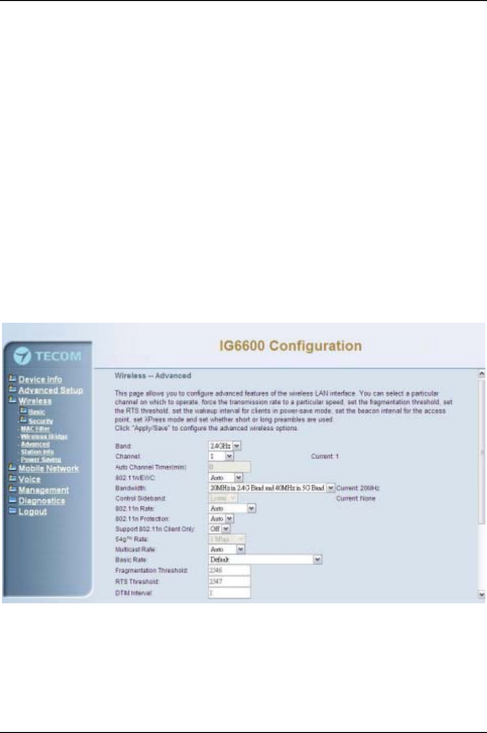
IG6600 Administration Manual
Page 68 of 139
maximize 802.11n throughput under most conditions. Do not disable 802.11n
protection if there is a possibility that 802.11b or 802.11g devices will use your
wireless network.
Support 802.11n Client Only:“On”enables support for 802.11n clients only. Off will
enable support for clients that are not 802.11n.
54g®Rate: The default setting is Auto. The range is from 1 to 54Mbps. The rate of
data transmission should be set depending on the speed of your wireless network.
You can select from one transmission speed, or keep the default setting, Auto, to
have the IAD automatically use the fastest possible data rate.
Multicast Rate: The default setting is 54Mbps. The range is from 1 to 54Mbps. The
rate of data transmission should be set depending on the speed of your wireless
network. You can select from one transmission speed, or keep the default setting, to
have the IAD automatically use the fastest data rate for multicast packets.
Basic Rate: Select the basic rate that wireless clients must support.
Fragmentation Threshold: This value should remain at its default setting of 2346.
The range is 256~2346 bytes. It specifies the maximum size for a packet before data
is fragmented into multiple packets. If you experience a high packet error rate, you
may slightly increase the Fragmentation Threshold. Setting this value too low may
result in poor network performance. Only minor modifications of this value are
recommended.
Figure 6-53. Wireless –Advanced –1
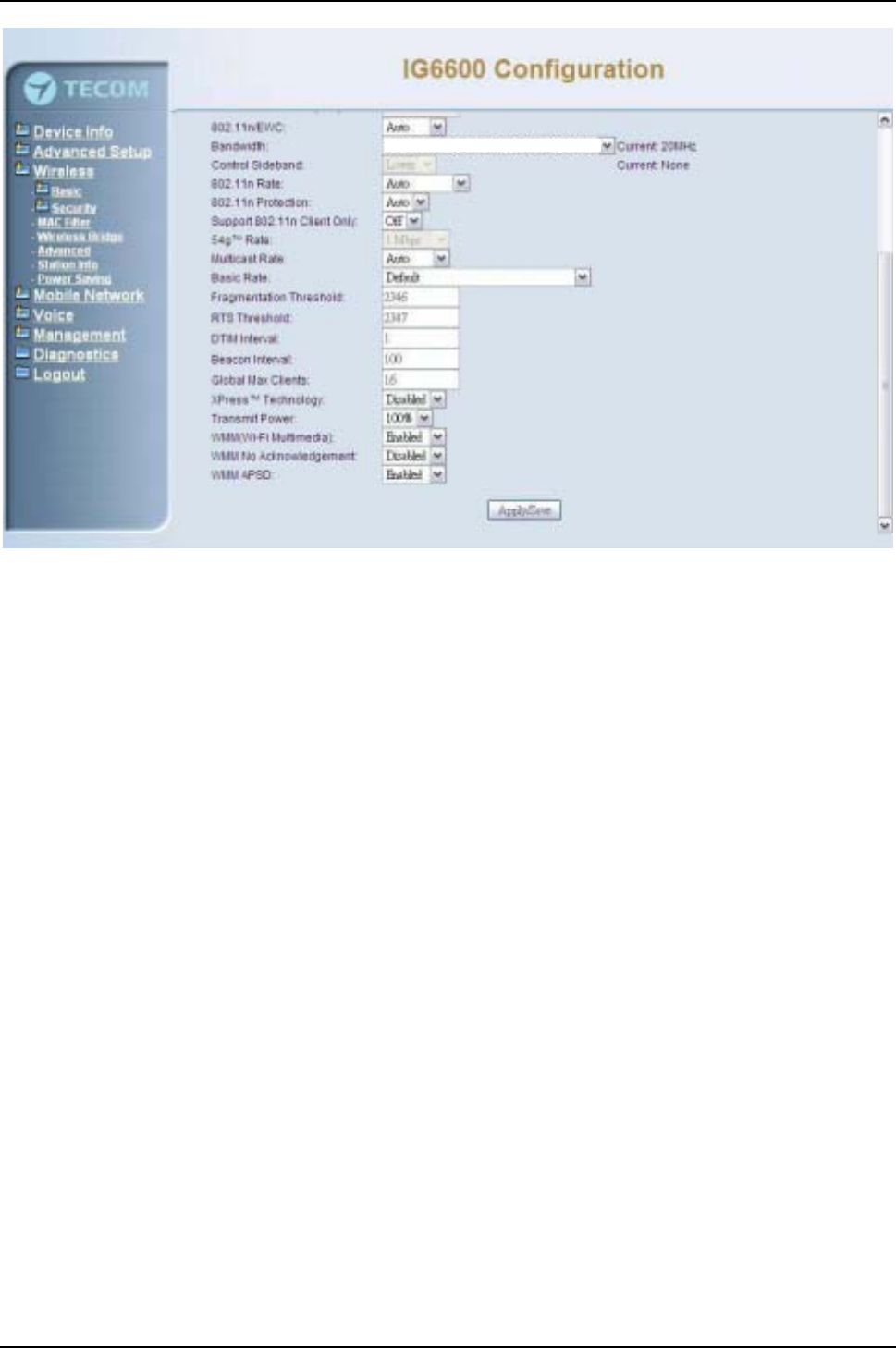
IG6600 Administration Manual
Page 69 of 139
Figure 6-54. Wireless –Advanced –2
RTS Threshold: This value should remain at its default setting of 2347. The range is
0~2347 bytes. Should you encounter inconsistent data flow, only minor modifications
are recommended. If a network packet is smaller than the packet RTS threshold size,
the RTS/CTS mechanism will not be enabled. The IAD sends Request of Send (RTS)
frames to a particular receiving station and negotiates the sending of a data frame.
After receiving an RTS, the wireless station responds with a Clear to Send (CTS)
frame to acknowledge the right to begin transmission.
DTIM Interval: The default value is 3. This value, between 1 and 255 milliseconds,
indicates the interval of the Delivery Traffic Indication Message (DTIM). A DTIM field
is a countdown field informing clients of the next window for listening to broadcast
and multicast messages. When the router has buffered broadcast or multicast for
associated clients, it sends the next DTIM with a DTIM Interval value. Its clients hear
the beacons and awaken to receive the broadcast and multicast message.
Beacon Interval: The default value is 100. Enter a value between 1 and 65535
milliseconds. The Beacon Interval value indicates the frequency interval of the
beacon. A beacon is a packet broadcast by the router to synchronize the wireless
network.
Global Max Clients: Maximum number of wireless clients.
XPress™Technology: Select “Enable” to improve the wireless performance. It is a
technology that utilizes standards based on framebursting to achieve higher
throughput.
Transmit Power: User can set the transmit power as 20%, 40%, 60%, 80% and
100%
WMM (Wi-Fi Multimedia): Feature that improves the experience for audio, video and
voice applications over a Wi-Fi network.
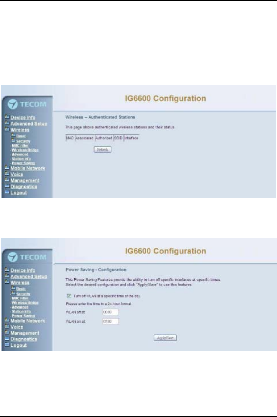
IG6600 Administration Manual
Page 70 of 139
WMM No Acknowledgement: When the “WMM No Acknowledgement" is enabled,
the receiver will not acknowledge received packets during wireless packet transmit. It
is suitable in the environment where communication quality is good and interference
is weak. It can improve transmission efficiency.
WMM APSD: WMM Automatic Power Save Delivery. APSD is useful for VoIP phone
to achieve low power consumption.
6.5.6 Station Info
Authenticated wireless stations and their status will be shown here. (Figure 6-55)
Figure 6-55. Wireless –Station Info
6.5.7 Power Saving
The Power Saving Features provide the ability to turn off specific interfaces at specific
times. (Figure 6-56)
Figure 6-56. Wireless –Power Saving
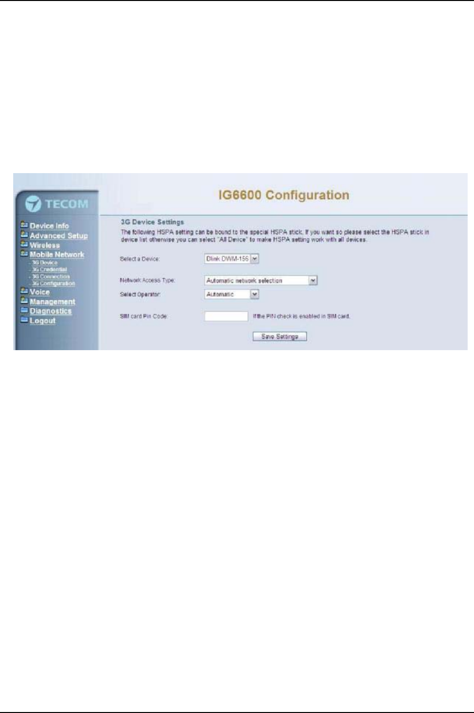
IG6600 Administration Manual
Page 71 of 139
6.6MobileNetwork
The IG6600 provides the WAN failover feature which allows gateway to reroute the
traffic to the 3G WAN interface when main Ethernet WAN interface is down. Once the
main Ethernet WAN is back, the traffic will fall back to Ethernet WAN.
6.6.1 3G Device
The following HSPA setting can be bound to the special HSPA stick, If you want so
please select the HSPA stick in device list. User can select prefer Network Access Type
and service operator. If your SIM Card has PIN lock, the PIN Code form allows user to
enter the PIN code. (Figure 6.57)
Figure 6-57. Mobile –3G Device
6.6.2 3G Credential Settings
Before establish the 3G backup, user need to configure the mobile network connection
settings which provide by your service provider.
zDial Number: The dial number is provided by your service subscriber. Please check
with your subscriber.
zAccess Point Name: The APN (Access Point Name) is the name used to identify
packet service in the 3G/2G mobile network. The APN defines the type of service
that is provided in the packet data connection.
zUsername/Password: User can enter the username/password here.
zAuthentication: The network connection authentication.
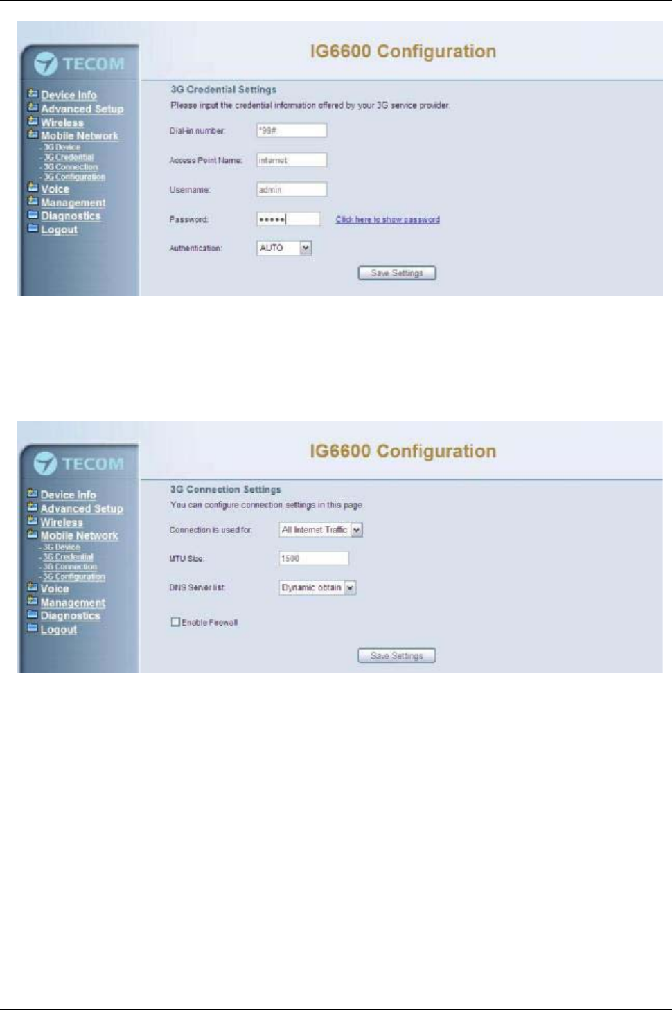
IG6600 Administration Manual
Page 72 of 139
Figure 6-58. Mobile –3G Credential
6.6.3 3G Connection Setting
User can configure the connection preference that Include connection usage, MTU Size,
DNS Server.
Figure 6-59. Mobile –3G Connction
6.6.4 3G configuration
Here allows user to setup the 3G WAN interface back up configuration. The instant
activation will switch back to main WAN interface when it is available. The WAN
interface fail test mode can be WAN interface status or PING responses of DGW and
DNS.

IG6600 Administration Manual
Page 73 of 139
Figure 6-60. Mobile –3G Configuration

IG6600 Administration Manual
Page 74 of 139
6.7 Voice
Use the Voice screen to configure the IG6600’s voice related parameters. It allows
system administrator to configure the following topics:
zPhone
-Phone Extension
-Extension Linekey
zTrunk
-IP Trunk
-Trunk Group
-Answering Position
-Call Routing
-Call Restriction
-Emergency Numbers
zSystem
-Numbering Plan
-Service Mode
-Transmission
-IGW Group
-SMDR
-ICD Call Log
zVoicemail
-General
-Extension
-Holiday
-Advanced
zRegistered Phone
The configurable items for each part would be described in the following.
6.7.1 Phone
Use the Phone screen to configure IG6600’s phone extension authentication and
configure the default linekey setting.
6.7.1.1 Phone Extension
The IG6600 combines Proxy and Register servers in its application. All phones
registered to the internal Register server are set here. (Figure 6-61,Figure 6-62)
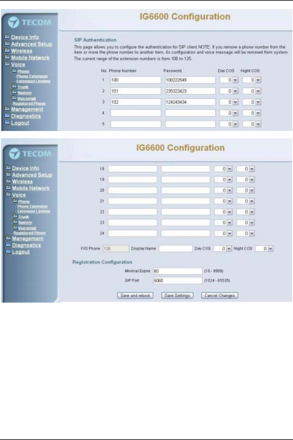
IG6600 Administration Manual
Page 75 of 139
Figure 6-61. Voice –Phone –Phone Extension –1
Figure 6-62. Voice –Phone –Phone Extension –2
SIP Authentication: It provides 24 IP phones to register.
Phone Number: The phone number is a station number. If it conflicts with the setting
in Numbering Plan, it fails to add or make the change. Its value range is limited by
Start Extension Number and End Extension Number settings in Numbering Plan
page.
Password: The user password of this phone. The length is up to 24 digits or
characters. It’s used for Digest Authentication.
Day COS: The field assigns Class of Service for day mode operation. Acceptable
values are 0-7. At default, all extensions are unrestricted.
Night COS: The field assigns Class of Service for night mode operation. Acceptable
values are 0-7. At default, all extensions are unrestricted.
FXS Phone: It shows the FXS phone number. It’s programmed in Numbering Plan.
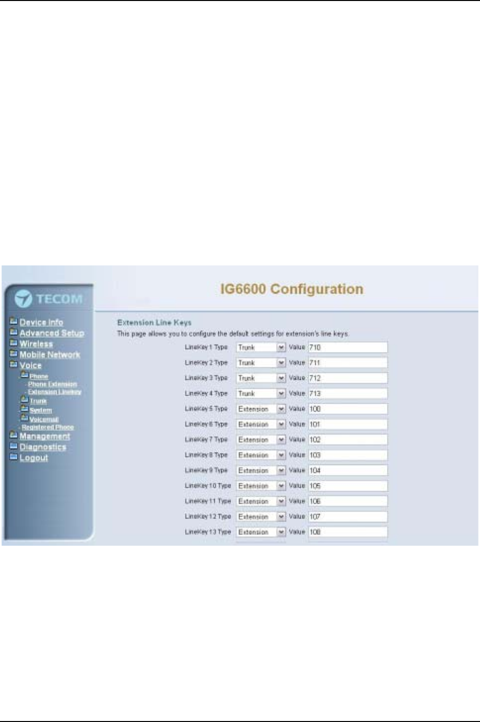
IG6600 Administration Manual
Page 76 of 139
Display Name: The FXS user’sCallingName.
Registration Configuration:
Minimal Expire: Minimal registered period of IP phone.
SIP Port: The IG6600 listens for requests on the SIP port. This port is used for UDP
application and 5060 is its recommended value.
6.7.1.2 Extension Linekey
This page allows you to configure the default settings for IP phone’s linekeys. While a
new-allocated IP phone is registering to IG6600, IG6600 will send these settings to the
phone. You can select Extension, Trunk, Call Park, Feature key and Others to these
linekey. (Figure 6-63) (Figure 6-64)
It has 28 Line Keys to be configured. The Line Keys 5-28 can be applied to IP2061’s
EDM.
Auto Hold: When you are using a line and press the other linekey, IG6600 can hold
the original line. Select “Enable”to open this function.
Figure 6-63. Voice –Phone –Extension Linekey-1
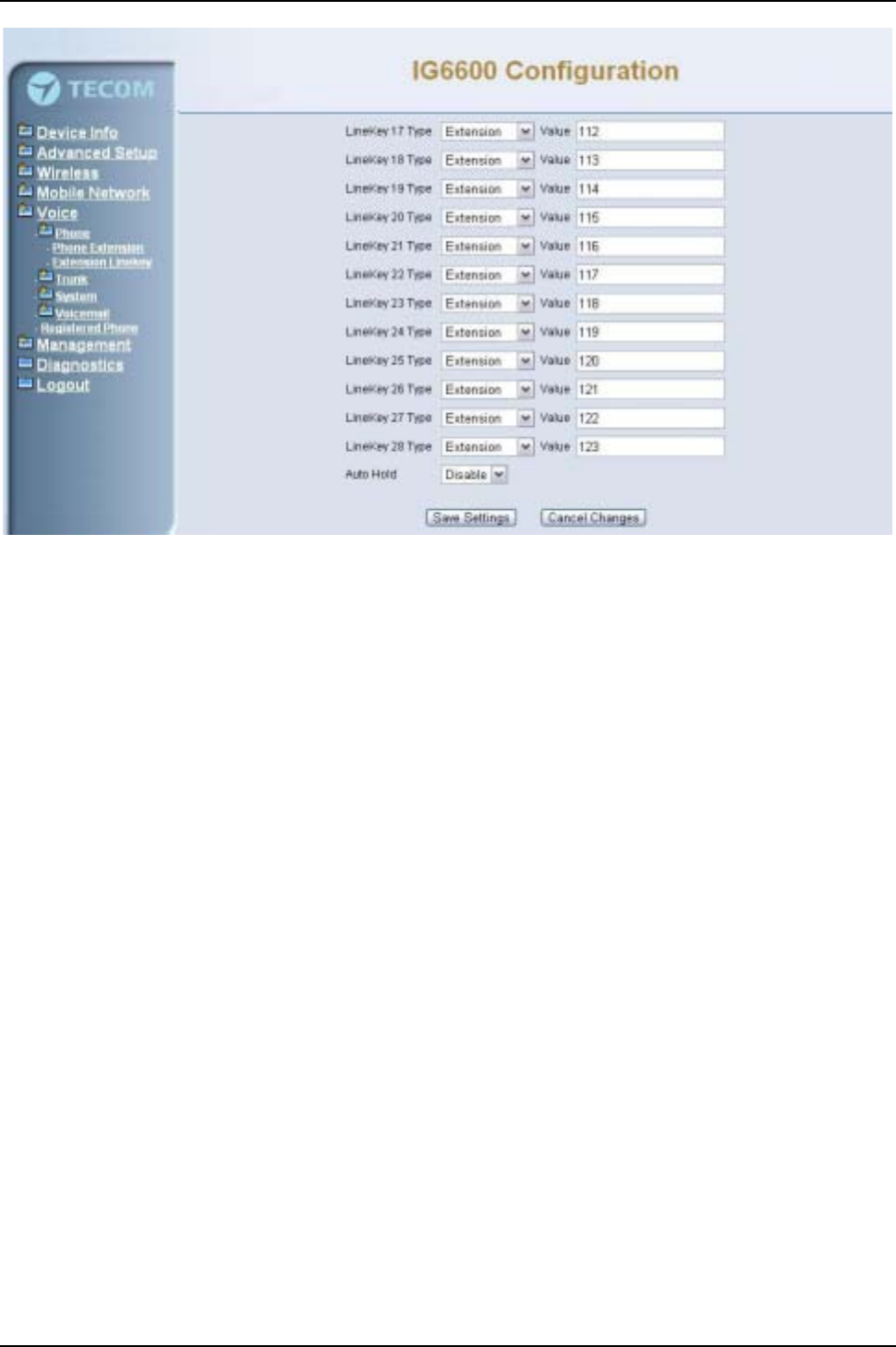
IG6600 Administration Manual
Page 77 of 139
Figure 6-64. Voice –Phone –Extension Linekey-2
6.7.2 Trunk
Use the Trunk screen to configure the PSTN/IP Trunk function related parameters. It is
separated into 6 parts:
zIP Trunk
zTrunk Group
zAnswering Position
zCall Routing
zCall Restriction
zEmergency Numbers
6.7.2.1 IP Trunk
This page allows you to configure the Proxy and Register server of IP Trunk, up to 8
lines of IP Trunk are supported. (Figure 6-65,Figure 6-66,Figure 6-67)
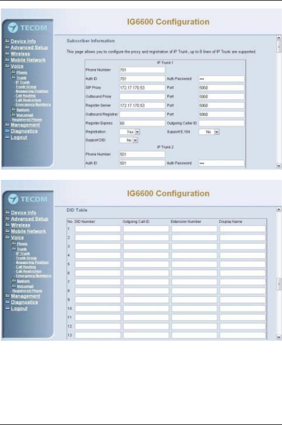
IG6600 Administration Manual
Page 78 of 139
Figure 6-65. Voice –Trunk –IP Trunk –1
Figure 6-66. Voice –Trunk –IP Trunk –2
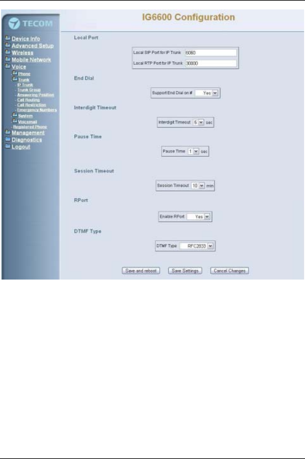
IG6600 Administration Manual
Page 79 of 139
Figure 6-67. Voice –Trunk –IP Trunk –3
Subscriber Information:
Phone Number: It’s the assigned phone number from uplink server.
Auth ID: The Account ID of registration to uplink server. It’s used for Digest
Authentication.
Auth Password: The Password of registration to uplink server. It’s used for Digest
Authentication.
SIP Proxy: The position of uplink SIP proxy server. IP address and domain name are
all supported.
SIP Proxy Port: The SIP signal port of uplink registrar server.
Outbound Proxy: The address of uplink outbound proxy server. All sip request
packet will be sent to this server that will determine their next hops.
Outbound Proxy Port: The SIP signal port of uplink outbound proxy server.
Register Proxy: The position of uplink register server. IP address and domain name
are all supported.

IG6600 Administration Manual
Page 80 of 139
Register Proxy Port: The SIP signal port of uplink registrar server.
Outbound Registrar: The address of uplink outbound Registrar server. All
REGISTER packets will be sent to this server that will determine their next hops.
Outbound Proxy Port: The SIP signal port of uplink outbound registrar server.
Register Expires: It’s the time for IG6600 sends REGISTER to uplink register server.
It counts based on second.
Outgoing Caller ID: It’s used as the Caller ID for the outgoing calls.
Registration: If “Registration”is No, the IP Trunk will not send REGISTER to the
Register Proxy.
Support E.164: If “Support E.164”is Yes, the IP Trunk follows E.164 format to send
to outgoing phone number.
Support DID: If “Support DID”is Yes, the IP Trunk is used in DID operation.
DID Table:
The table offers its individual phone number for each extension
DID Number: It’s the assigned phone number from uplink server.
Outgoing Call ID: It’s the assigned Caller ID number from uplink server.
Extension Number: the specified extension for the individual phone number.
Display Name: the specified extension user name for the individual number.
Local Port:
Local SIP Port for IP Trunk: SIP control signal packet Port of IP Trunk Client.
Local RTP Port for IP Trunk: Real-Time Protocol packet Port of IP Trunk Client. It’s
the start RTP port address for these IP Trunks.
End Dial:
If “Support End Dial on #”is Yes, outgoing number from IP trunk will be sent out
immediately after pressing pound key (#).
Interdigit Timeout:
If there is no any dialed number after the setting time, the number will be sent out
immediately. Its range is form 2 to 9 seconds.
Pause Time:
Session Timeout:
It means the longest communication time for IP trunks, zero means no restriction.
RPort:
When client is behind a NAT, the rport and received filed can allow SIP proxy to
append the public IP address and port of NAT and transfer SIP message correctly.
Choose “Enable” to use this function.
DTMF Type:
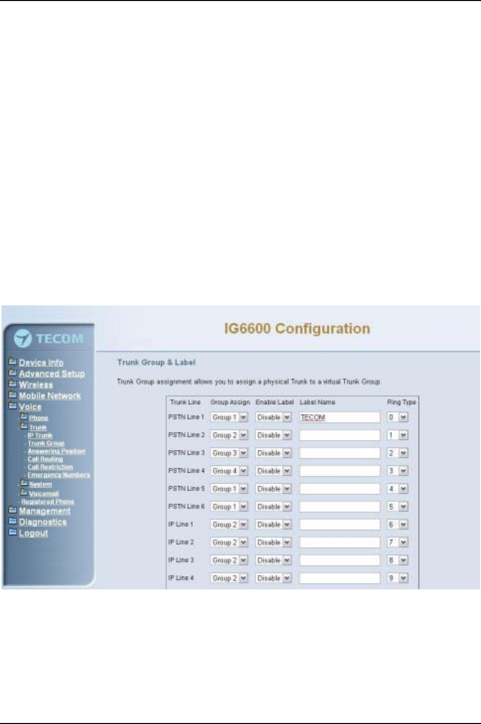
IG6600 Administration Manual
Page 81 of 139
In IG6600, there are two methods for transmitting DTMF tone. Select RFC2833
Method, the DTMF tone will be transmitted by event packet. Select SIP-INFO Method,
the DTMF tone will be represent in SIP INFO Message.
6.7.2.2 Trunk Group
This page allows you to configure the virtual Trunk Group, up to 4 Trunk Groups are
supported. (Figure 6-68,Figure 6-69)
Trunk Group & Label:
This item allows you to assign physical Trunk to virtual Trunk Group. And you can
configure your personal string as incoming Caller ID number. For six PSTN lines and
eight IP lines you can choose from Group1 to Group 4.
Ring Type:
It can identify the trunk line and the trunk group to which it belongs to.
Trunk Group Priority:
This Item allows you to define 4 Trunk Group's interior priority. For four groups you
can choose IP first or PSTN first. This will take effect if call routing entry’s destination
has been set as Group choice.
Figure 6-68. Voice –Trunk –Trunk Group –1
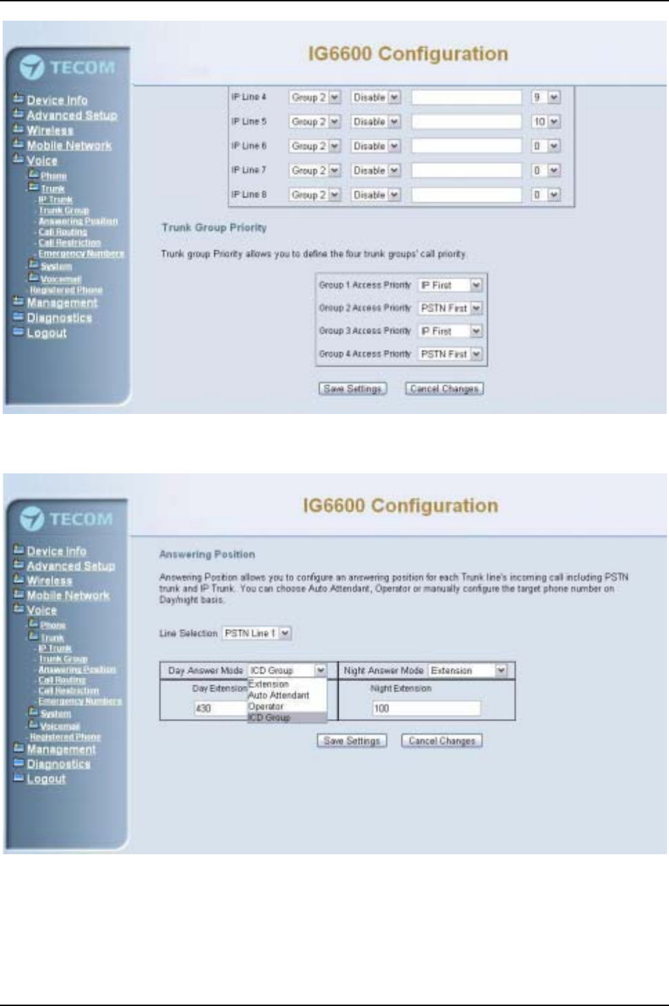
IG6600 Administration Manual
Page 82 of 139
Figure 6-69. Voice –Trunk –Trunk Group –2
6.7.2.3 Answering Position
Figure 6-70. Voice –Trunk –Answering Positions
This page allows you to configure an answering position for each Trunk line's incoming
call including PSTN trunk and IP Trunk. You can choose Auto Attendant, Operator, ICD
Group or manually configure the target extension phone number on Day/night basis.
(Figure 6-70)
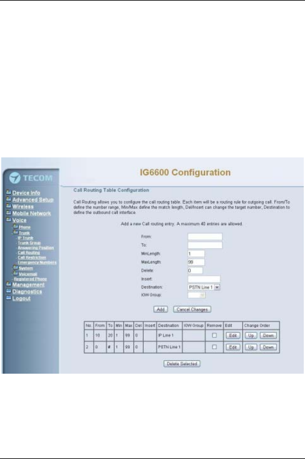
IG6600 Administration Manual
Page 83 of 139
Choose Auto Attendant, an idle VAA will auto-answer this incoming trunk call.
Choose Extension, you must configure the target phone number on Day/Night basis.
Choose ICD Group, you can configure an ICD group. The maximum phones for one ICD
group are 25.
Choose Operator, the incoming trunk call will be redirected to Operator.
6.7.2.4 Call Routing
This page allows you to configure the call routing table. Each item is a routing rule for
outgoing call. From/To define the number range, Min/Max define the match length,
Del/Insert can change the target number, Destination to define the outbound call
interface.
In the Destination field, the drop list includes a particular option: “IGW Group”. When
selecting “IGW Group”, the next field “I”contains the founded IG6600’s name which is
maintained by the IGW group, and you can select a suitable IG6600 to route your calls.
(Figure 6-71)
Figure 6-71. Voice –Trunk –Call Routing Table
6.7.2.5 Call Restriction
This page allows you to configure the call restriction table. If the caller's COS priority is
higher than the entry's COS value, the call is allowed. (Figure 6-72)
The allowed intervals are made up of “From”and “To”entry which establish a numeric
range. For example, an entry of “From 1700”,“To 1800”would include the following
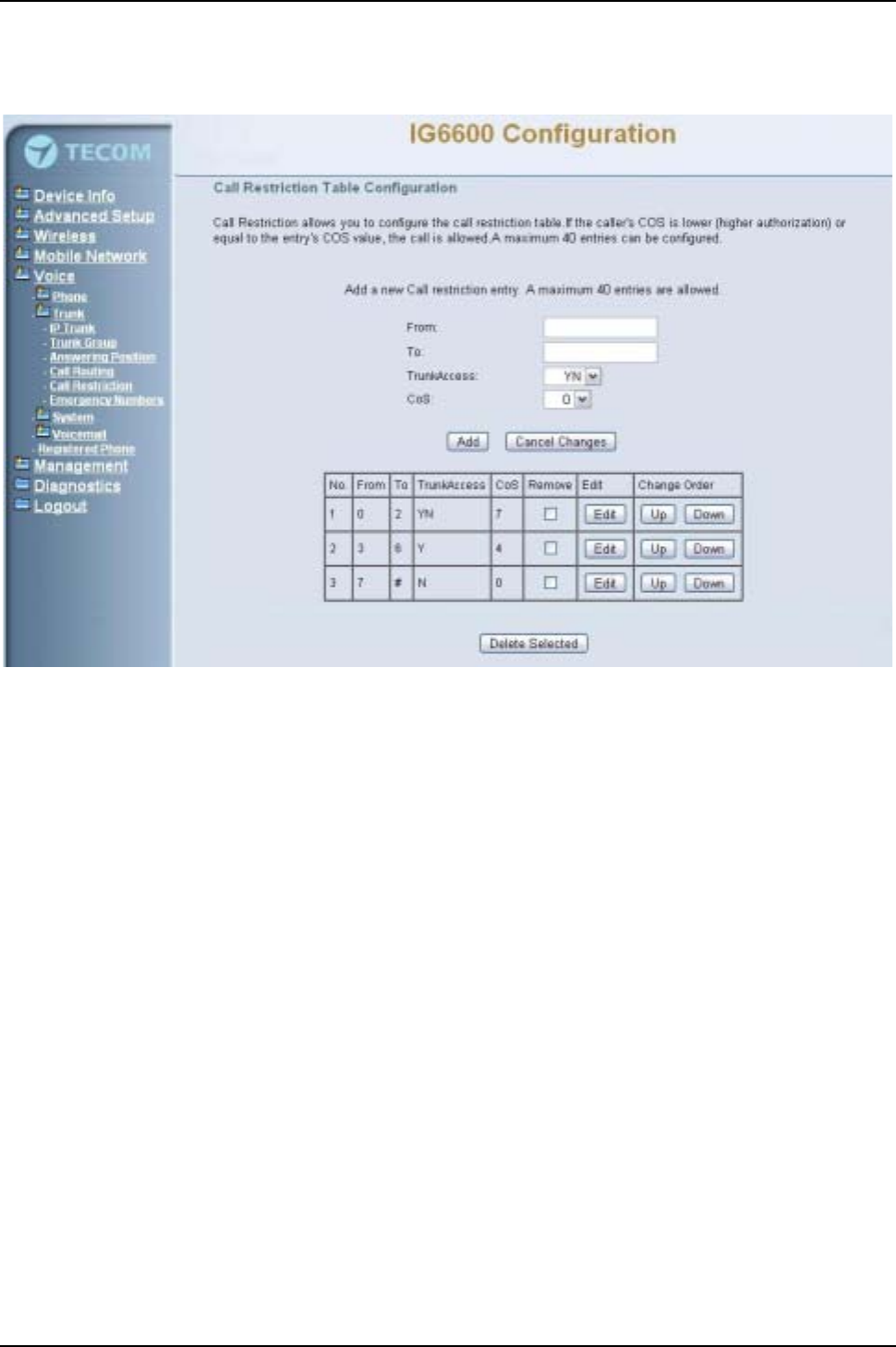
IG6600 Administration Manual
Page 84 of 139
range of numbers as the leading: 1700, 1701, 1702, …, 1799, 1800. Each From/To
entry can be from 1 to 13 digits long and may contain any digit 0-9. The “From”entry
must be less than or equal to the “To”entry.
Figure 6-72. Voice –Trunk –Call Restriction
If the TrunkAccess value is set to Y, the call will follow the restriction setting only when
seizing line and make a call. If the TrunkAccess value is set to N, the call will follow the
restriction only when dialing a number directly. If the TrunkAccess value is set to YN, it’s
suitable for both operations.
6.7.2.6 Emergency Numbers
When they dial a pre-configured emergency number, any user can make an emergency
call regardless of call routing table, call restriction, and station lock. Notice: The numbers
of emergency dial must not collide with the numbers in Numbering Plan.
This page allows you configure five emergency call numbers and lines with which
emergency calls are sent out. (Figure 6-73)
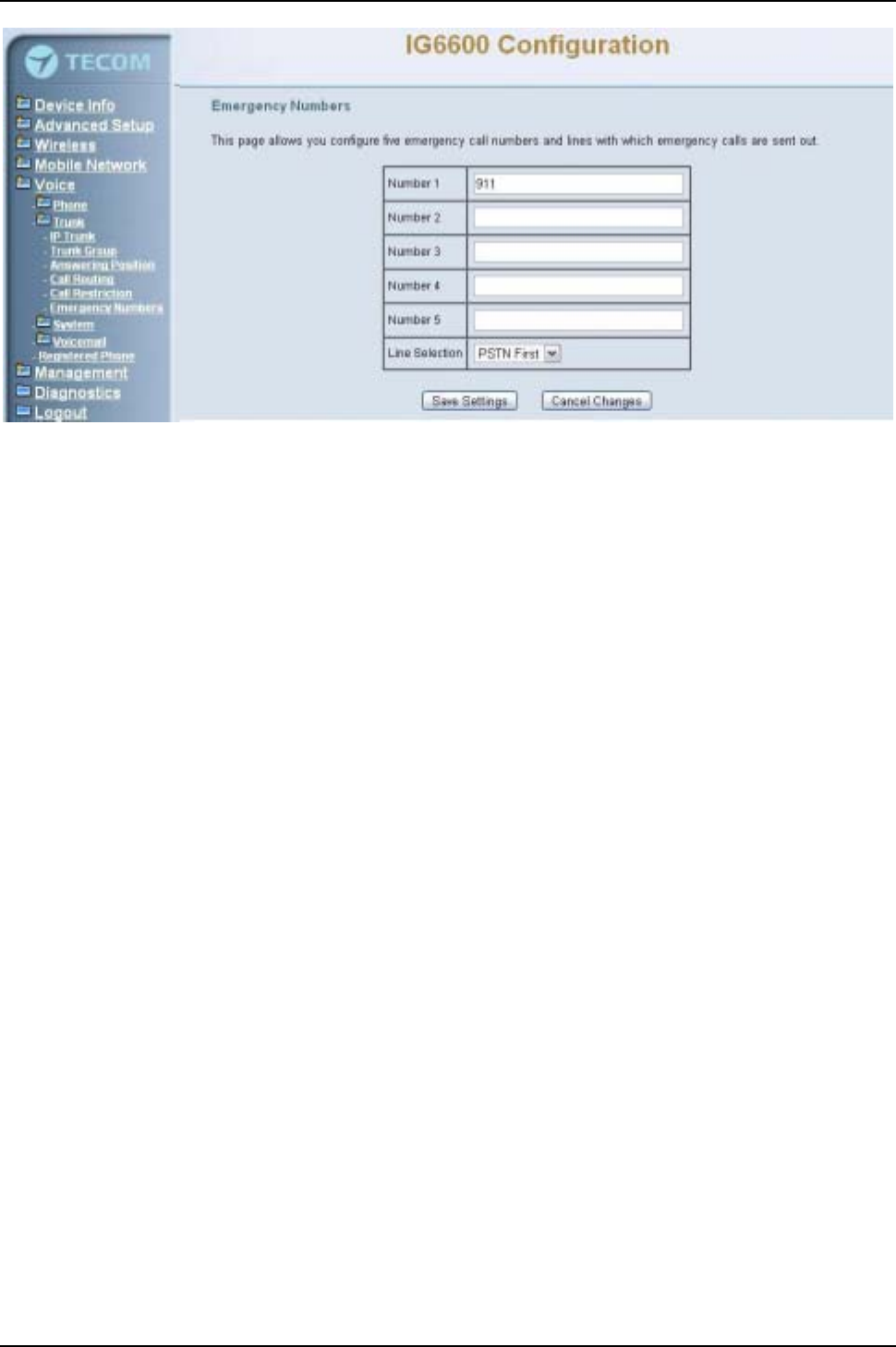
IG6600 Administration Manual
Page 85 of 139
Figure 6-73. Voice –Trunk –Emergency Dial
6.7.3 System
Use the System screen to configure the System function related parameters. It is
separated into 6 parts:
zNumbering Plan
zService Mode
zTransmission
zIGW Group
zSMDR
zICD Call Log
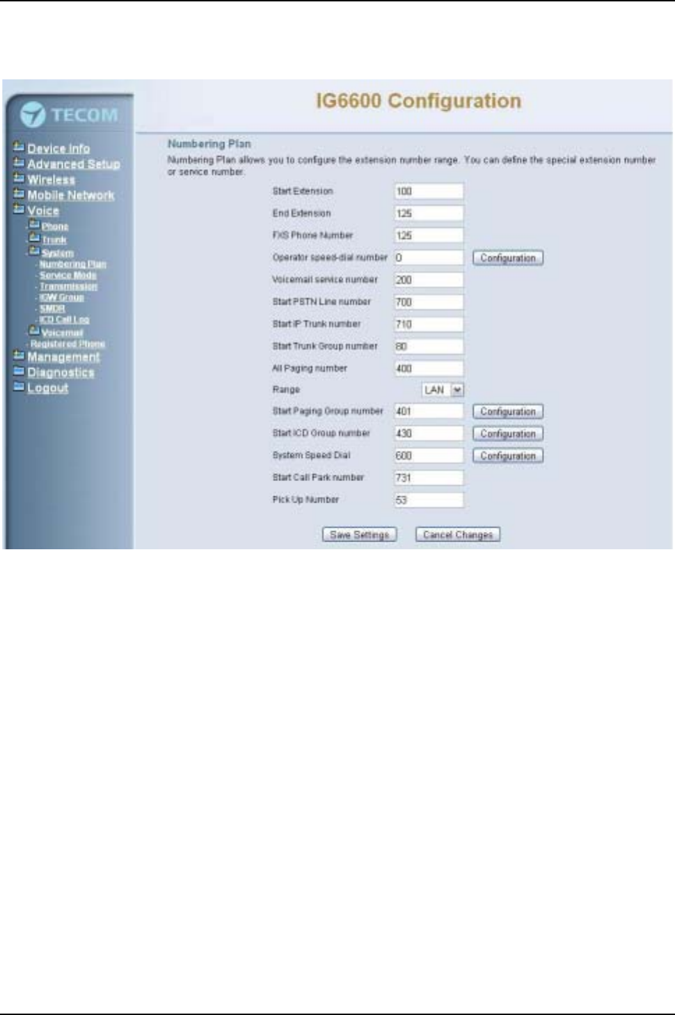
IG6600 Administration Manual
Page 86 of 139
6.7.3.1 Numbering Plan
Figure 6-74. Voice –System –Numbering Plan
This page allows you to configure extension number range. You can also define some
special service numbers in the table. (Figure 6-74)
Start extension: It’s the start phone number of system internal extension. All valid
extension number can’t be smaller than it.
End extension: It’s the end phone number of system internal extension. All valid
extension number can’t be greater than it. If receiving an IP20xx’sPlug&Play
request, IG6600 will allocate the first unused number from this limited region.
FXS Phone Number: It determines the FXS phone number.
Operator speed-dial number: If dial this number, the operator extension will be
called. The length is limited on 1 character.
When you press the “Configuration”button, the operator-related settings can be
configured: (Figure 6-75)
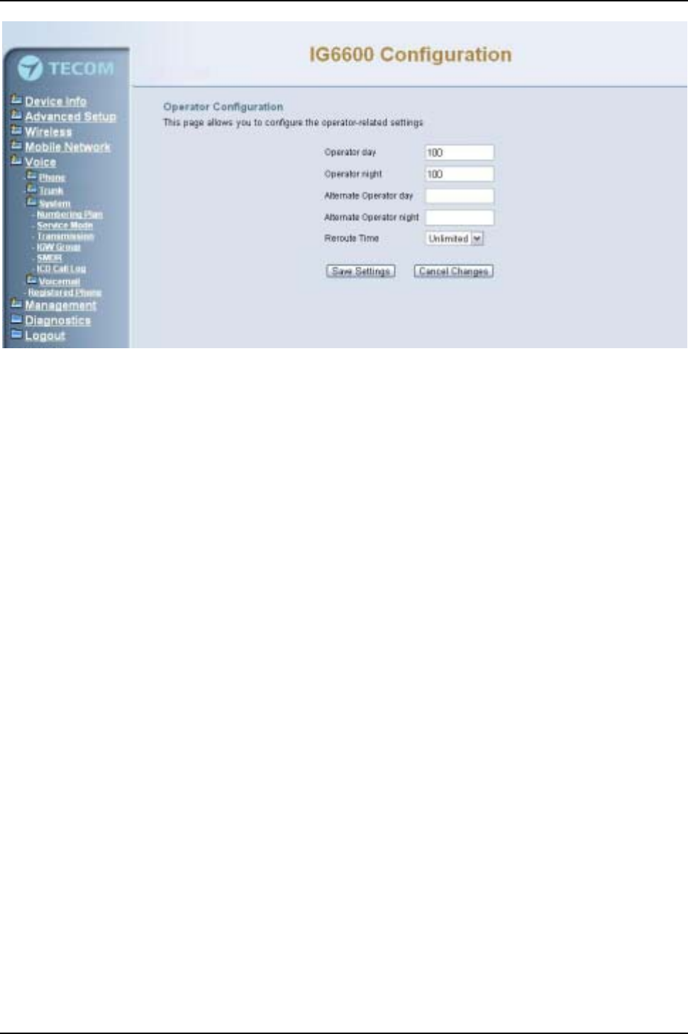
IG6600 Administration Manual
Page 87 of 139
Figure 6-75. Voice –System –Numbering Plan – Operator Configuration
Operator day: It’s the system operator number during day. If dial Operator
speed-dial number, this extension will be called during day.
Operator Night: It’s the system operator number during night. If dial Operator
speed-dial number, this extension will be called during night.
Alternate Operator day: When the Operator during day does not answer a call,
the call will be rerouted to alternate operator during day.
Alternate Operator night: When the Operator during night does not answer a call,
the call will be rerouted to alternate operator during night.
Reroute Time: Set the length of operator no answer time to reroute to alternate
operator. The time is applied to the call for alternate operator also. If alternate
operator doesn’t answer the call in the Reroute time, the call is reroute to
Operator’s Voice Mail box. “Unlimited”means it keeps ringing to the operator.
Voice mail service number: If dial this number, internal user can enter IG6600’s
voicemail system and do some operations such as listening personal message.
Start PSTN Line number: IG6600 provides 6 PSTN lines at most. Every line has its
own internal alias number. You can dial these numbers directly to access PSTN
trunks.
Start IP Trunk number: IG6600 provides 8 IP Trunk lines at most. Every line has its
own internal alias number. You can dial these numbers directly to access IP Trunks.
Start Trunk Group number: IG6600 provides 4 trunk groups at most. If dialing trunk
group number, IG6600 will choose the first idle line for caller automatically.
All Paging number: If dialing this number, all internal IP20xx will be paged. It can
select the range of the paged extensions. If it’s LAN, it pages the IP20xx on IG6600’s
LAN side. If it’s WAN, it pages the IP200xx on IG6600 WAN side, but under the same
Router with IG6600. If it’s Both, it pages the all IP20xx on LAN and WAN.
Start Paging Group number: 3 paging groups are defined in IG6600. If dialing a
Paging Group number, the call will page to predefined internal IP phones. It can also
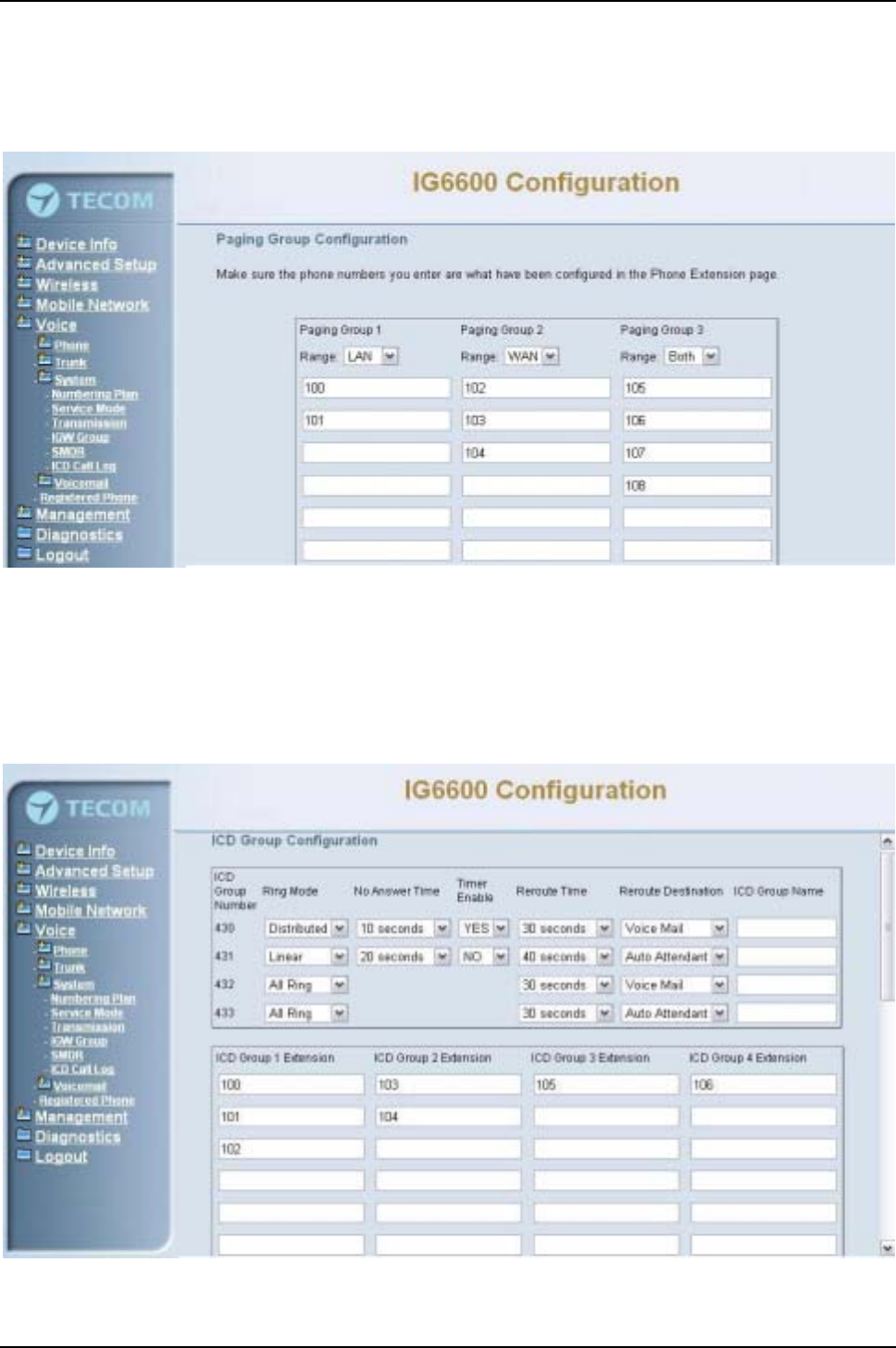
IG6600 Administration Manual
Page 88 of 139
select the Range like All Paging Number. The maximum phones for each paging
group are 24.
While pressing “Configuration”in “Start Paging Group number”, it shows Paging
Group Configuration screen. (Figure 6-76)
Figure 6-76. Voice –System –Numbering Plan –Paging Group
Start ICD Group number: 4 ICD groups are defined in IG6600. The maximum
phones for each ICD group are 25. If one ICD Group is assigned to Answer Position
of certain line, when there is an incoming trunk call, extensions of the ICD group will
be called and ringing
While pressing “Configuration”in “Start ICD Group number”, it shows ICD Group
Configuration screen. (Figure 6-77)
Figure 6-77. Voice –System –Numbering Plan –ICD Group
There are six items to be decided.
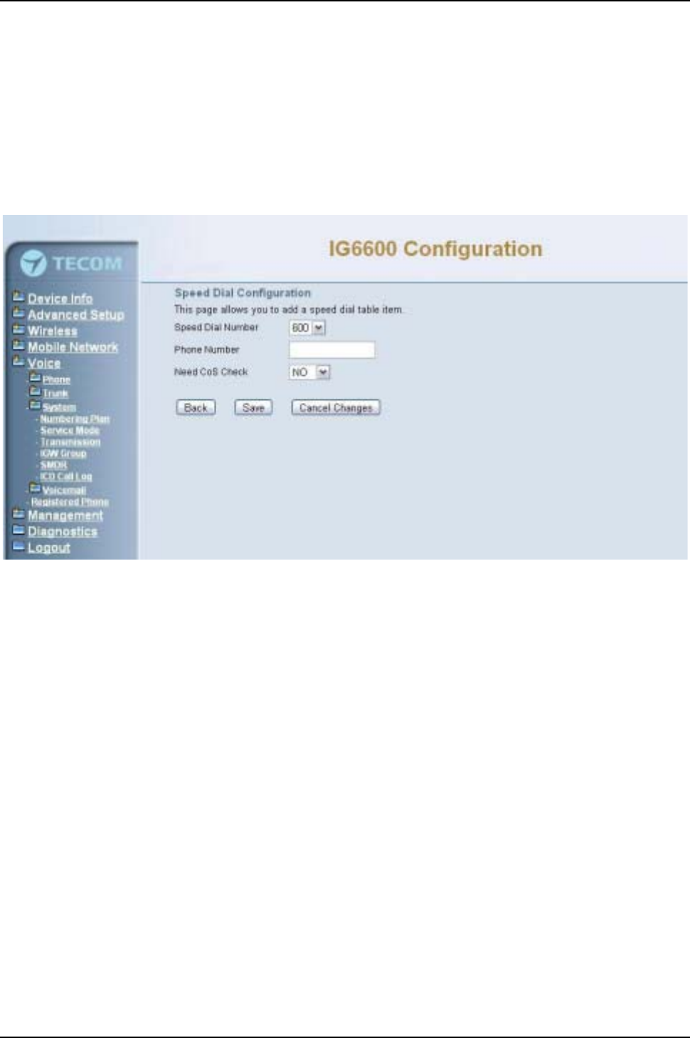
IG6600 Administration Manual
Page 89 of 139
For Ring Mode: The “All Ring”mode is no needed to use “No Answer Time”and
“Timer Enable”.
For other items: If “Timer Enable”is YES, the incoming call will be transferred to
another ICD Group’s member every “No Answer Time”. If NO, the call will ignore “No
Answer Time”and finally reroute to “Reroute Destination”after “Reroute Time”.“ICD
Group Name”is shown on the phone when receiving the ICD Group call.
System Speed Dial: Speed Dialing allows you to store frequently outgoing numbers.
There are 100 sets to configure (600~699). Extension’s Class of service (COS) can
also be checked or not. (Figure 6-78)
Figure 6-78. Voice –System –Speed Dial
Start Call Park Number: IG6600 supports to park 4 trunk calls maximum. The Call
Park number can be programmed on the line keys.
6.7.3.2 Service Mode
This page allows you to configure the day/night/time service mode. You can also
customize the working time manually for each weekday.
If you choose Time Mode, it’s for the specified day of week. The time is entered in
24-hour format. Valid entries are 00:00 to 23:59 in 1-minute increments. (Figure 6-79)
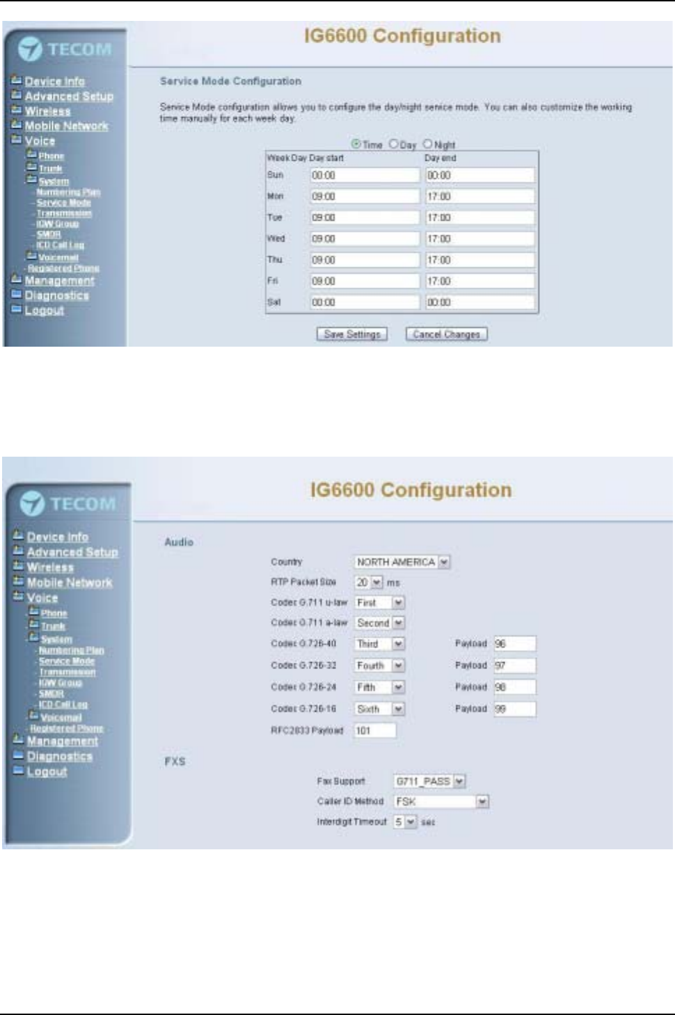
IG6600 Administration Manual
Page 90 of 139
Figure 6-79. Voice –System –Service Mode
6.7.3.3 Transmission
This page allows you to configure the Audio, FXS, and FXO settings. Click “Save
Settings”button to save the new configuration. (Figure 6-80,Figure 6-81)
Figure 6-80. Voice –System –Transmission –1
Audio: It is used to set many Audio-related options. It will be applied to the all FXS and
PSTN lines.
Country: It may be used to determine not only the Caller ID detection/transmission
method but also ring/tone cadence/frequency.
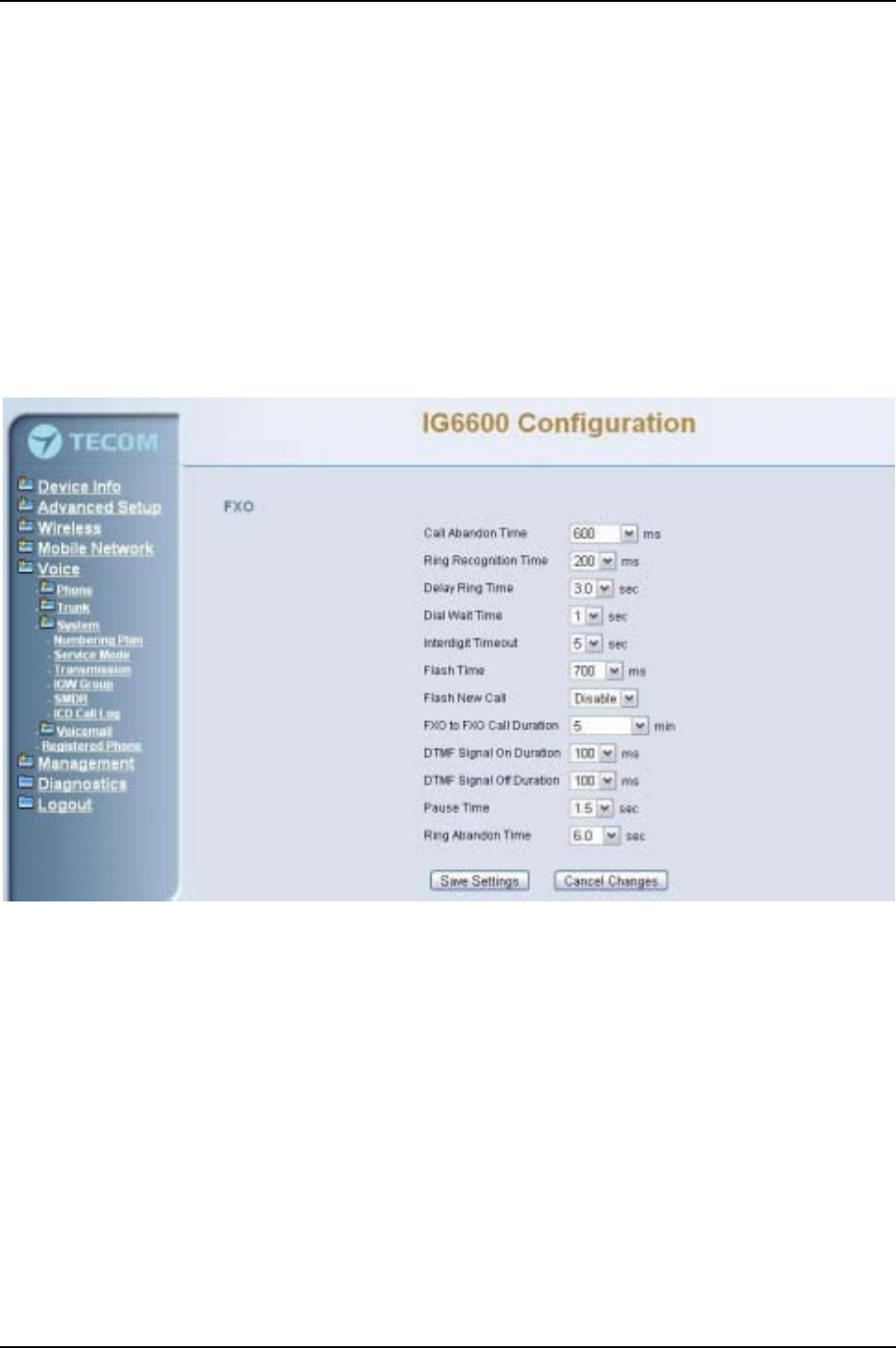
IG6600 Administration Manual
Page 91 of 139
RTP Packet Size: 10/20/30/40/50/60 ms.
Codec G.711 u-law, G.711 a-law, G.726-16, G.726-24, G.726-32, G.726-40: IG6600
supports different audio priority. You can choose “None”,“First”,“Second”,“Third”,
“Fourth”,“Fifth”and “Sixth”.
FXS: It is used to set many FXS-related options.
Fax Support: The system supports FAX/modem tone detection with G.711 and T38
mode.
Call ID Method: The system provides the ability to detect the calling party
identification provided by PSTN lines. It also transmits the calling party identification
to POTS ports. There are four choices: NONE, DTMF_BR, DTMF_AR, FSK.
Inter-digit Timeout: Its range is from 2 to 9 seconds.
Figure 6-81. Voice –System –Transmission –2
FXO: It is used to set many central office line options.
Call Abandon Time: For every PSTN/FXO call, system provides the facility to
monitor the call status. If the remote party hangs up, the ongoing call must be
terminated. The PSTN line monitor is done by the loop-break signal or busy tone.
The value range is: Disable/100/200/…/1000 ms.
Ring Recognition Time: The timer determines the minimum ring duration
recognized as a valid incoming ring on a FXO port. Shorter ring signals are ignored.
The timer range is 200ms to 600ms in 40ms increments.
Delay Ring Time: The timer is to allow the Central Office to send ICLID before the
call is answered. Once the timer expires, the programmed extensions will ring and
the ICLID number will be sent to the ringing extensions. The timer range is 3 to 6
seconds on 0.5 second increments.
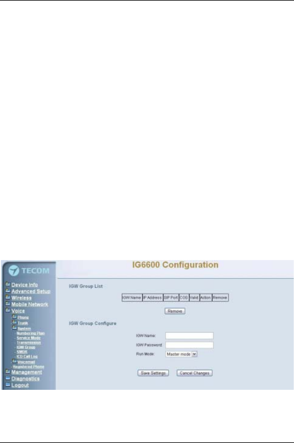
IG6600 Administration Manual
Page 92 of 139
Dial Wait Time: When the user seizes a PSTN/FXO line, the Stable Time delay is
needed to wait the dial tone from Central Office. Its range is from 350 to 950 ms.
Inter-digit Timeout: Its range is from 2 to 9 seconds.
Flash Time: The on-off duration for sending the FLASH signal. Its range is from 90 to
700 ms.
Flash New Call: If this item is set “Enable”, a call will be taken account of a new call
when the CO FLASH feature is used.
FXO to FXO Call Duration: The maximum calling time between two FXO lines.
DTMF Signal On/Off Duration: The on/off time duration of DTMF signal. Their
ranges are from 50 to 200 ms.
Pause Time: The pause time of alphabet “p”in the process of call dialing. The four
values are 1.5, 2.5, 3.5, and 4.5.
Ring Abandon Time: It specifies the maximum time between valid ring signals from
the CO/PBX. If the duration between rings exceed the Ring Abandon time, IG6600
stops ringing the destination(s) and the port returns to idle.
6.7.3.4 IGW Group
Several IG6600s can be set into an IGW Group. IGW Group’s members can share the
whole trunks.
In an IGW Group, one master IG6600 and at most 9 slave IG6600s are available.
Master IG6600 must have a public/static IP address. Master and all slave IG6600s
share one password for authentication. If the IP address of master is set in a slave
IG6600, slave IG6600 sends its IP address, name, and password to the master. Master
IG6600 verifies the received password and name. If the password is valid and the name
is not duplicated, master IG6600 sends the IGW list to all slave IG6600s. (Figure 6-82)
Figure 6-82. Voice –System –IG6600 Group
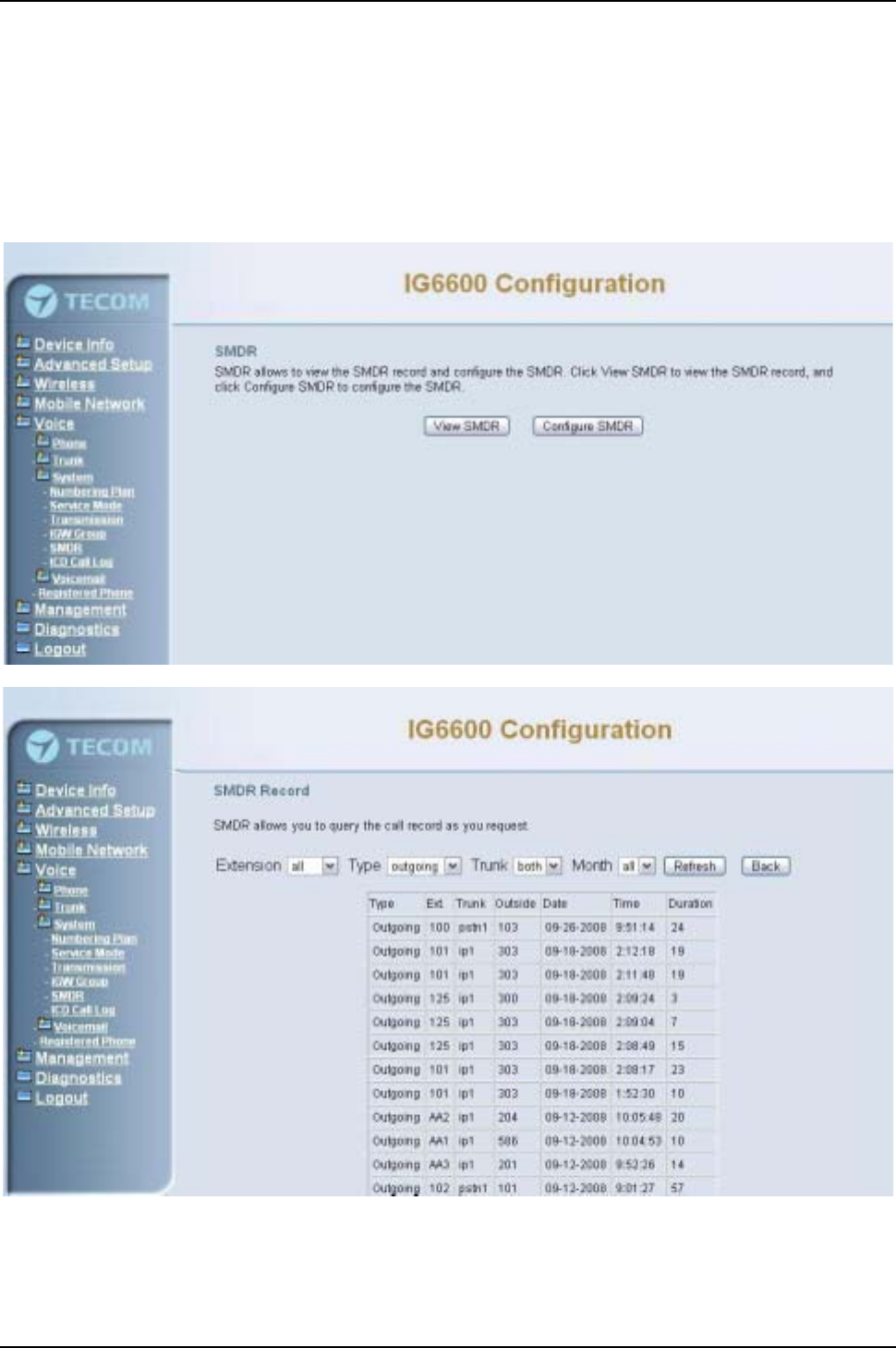
IG6600 Administration Manual
Page 93 of 139
6.7.3.5 SMDR
SMDR (Station Message Detail Recording) will take down user’s dialing record. It
contains every calling period. From the log of SMDR, the administrator can charge some
fees from the user.
This page allows you to view the SMDR record and configure the SMDR. Click “View
SMDR”button to view the SMDR record, and click “Configure SMDR”button to
configure the SMDR. (Figure 6-83,Figure 6-84,Figure 6-85)
Figure 6-83. Voice –System –SMDR
Figure 6-84. Voice –System –SMDR Record
The “PSTN Outgoing Call Duration Start Time”is used to estimate whether the PSTN
outgoing call to be recorded. If the duration is less than it, the call won't be recorded. If
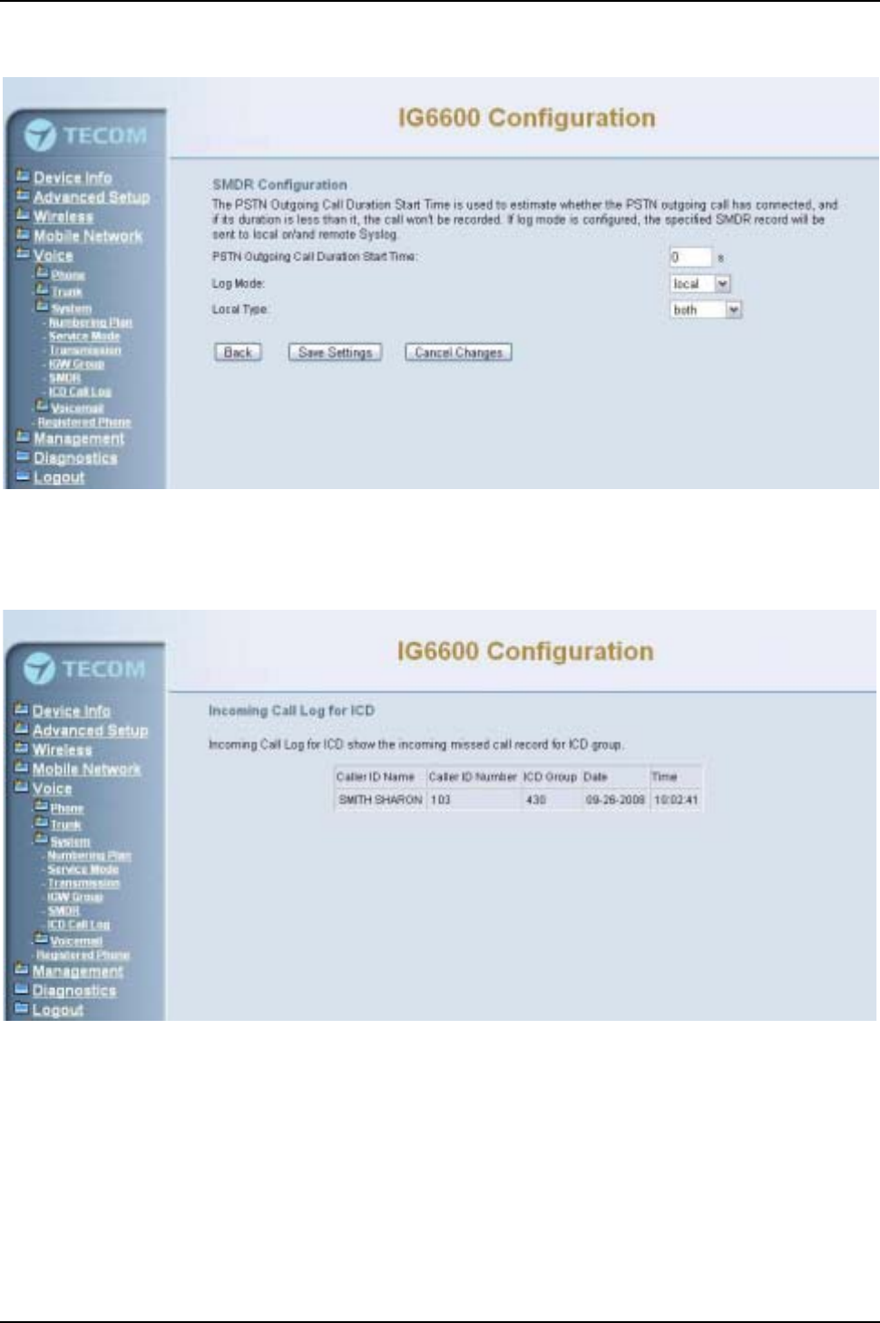
IG6600 Administration Manual
Page 94 of 139
log mode is configured, the specified SMDR record will be sent to local or/and remote
log server.
Figure 6-85. Voice –System –SMDR Configuration
6.7.3.6 ICD Call Log
This page shows the Call Log for incoming call to ICD group. (Figure 6-86)
Figure 6-86. Voice –System –ICD Call Log
6.7.4 Voice Mail
IG6600 provides a built-in Auto Attendant and Voice Mail System. It is separated into 4
parts:
zGeneral
zExtension
zHoliday
zAdvanced
The configurable items for each part would be described in the following.

IG6600 Administration Manual
Page 95 of 139
6.7.4.1 General
This page allows you to configure the general settings of the auto attendant and voice
mail. (Figure 6-87,Figure 6-88)
Auto Attendant:
Working Time: Weekday’s working time.
Saturday Working Time: 00000000 means Saturday Holiday.
Sunday Working Time: 00000000 means Sunday Holiday.
Lunch Break Time: The time for lunch break.
Admin Password: The password of administrator.
Max Try Time: Maximum error times for extension’s key input.
Action When Max Error Reached:You can set the system “Forward to operator”or
“Disconnect”when reaching the “Max Try Time”errors for key input.
Prompt Language: Automated Attendant language type. It provides one or two
languages to be chosen.
Voice Mail:
Email Notify with Voice Files: Add attached WAV file in notifying email for leaved
message.
Days for Keeping Voice Mail: Keep days for leaving messages. 0 means that the
messages are kept until the users delete them.
SMTP Support SSL: Choose “Yes” to support SSL.
SMTP Server: SMTP Mail Server.
SMTP Server Port: SMTP Mail Server port. The default value is 25.
Sender Email Address: Email Address of Sender.
Sender User Name: User Name of Sender’s Email.
Sender Password: Password of Sender’sEmail.
Max recording time:The range of recording time is form 1 to 30 minutes.
Silence detection for VM recording:Set “Enable”of this item will do the silence
detection in VM recording. If “silence”is detected, IG6600 will terminate the recording
and release the line.
Voicemail Tag: Voicemail tag
Email header: Email header
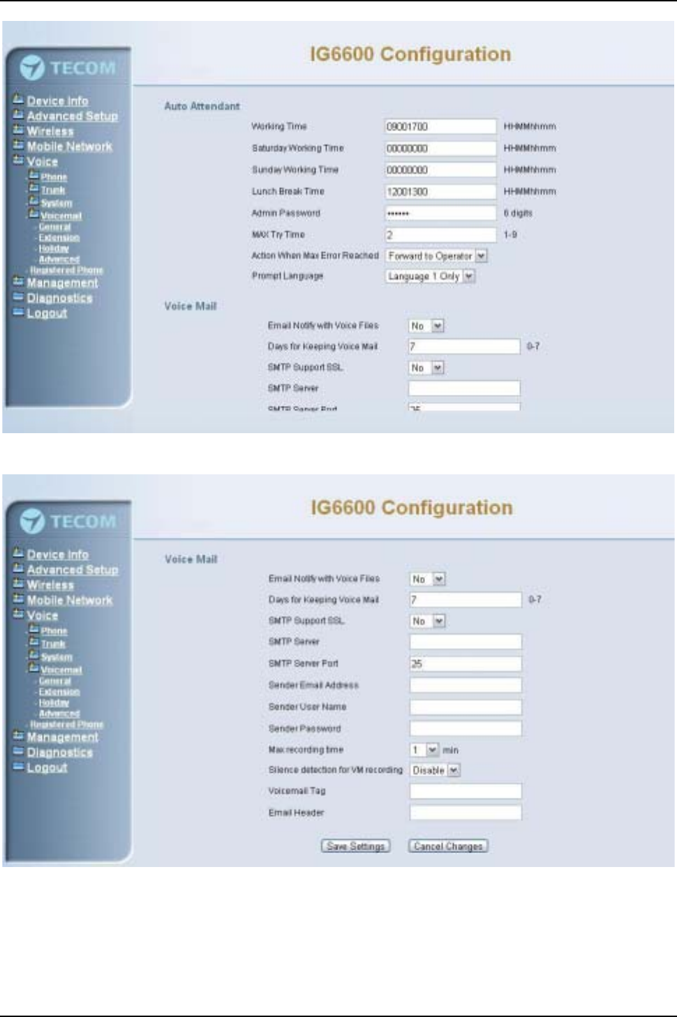
IG6600 Administration Manual
Page 96 of 139
Figure 6-87. Voice –Voice Mail – General –1
Figure 6-88. Voice –Voice Mail – General –2
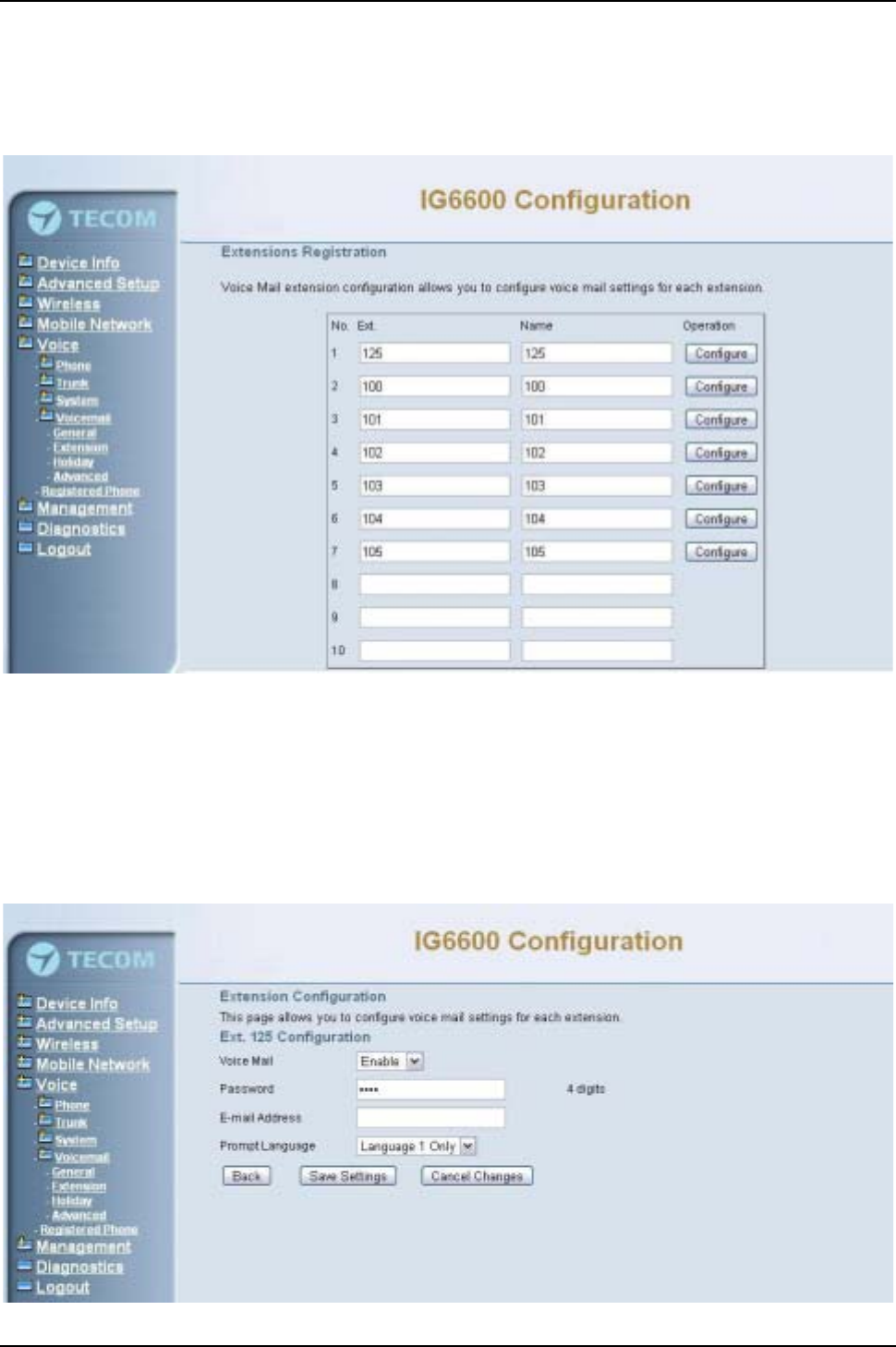
IG6600 Administration Manual
Page 97 of 139
6.7.4.2 Extension
Voice Mail extension configuration allows you to configure voice mail settings for each
extension. While pressing “Configure”, it shows Extension Voice Mail Configuration
screen. (Figure 6-89)
Figure 6-89. Voice –Voice Mail –Extension Registration
The following items will be configured in the Extension Configuration (Figure 6-90):
Voice Mail: Enable/Disable. To disable this item, there is not allowed to listen to the
message from outside party. (See Appendix 3.2.3)
Password: Password of voice mailbox of the extension.
E-mail Address: Phone user’s E-mail Address.
Prompt Language: Provides one or two language to be chosen.
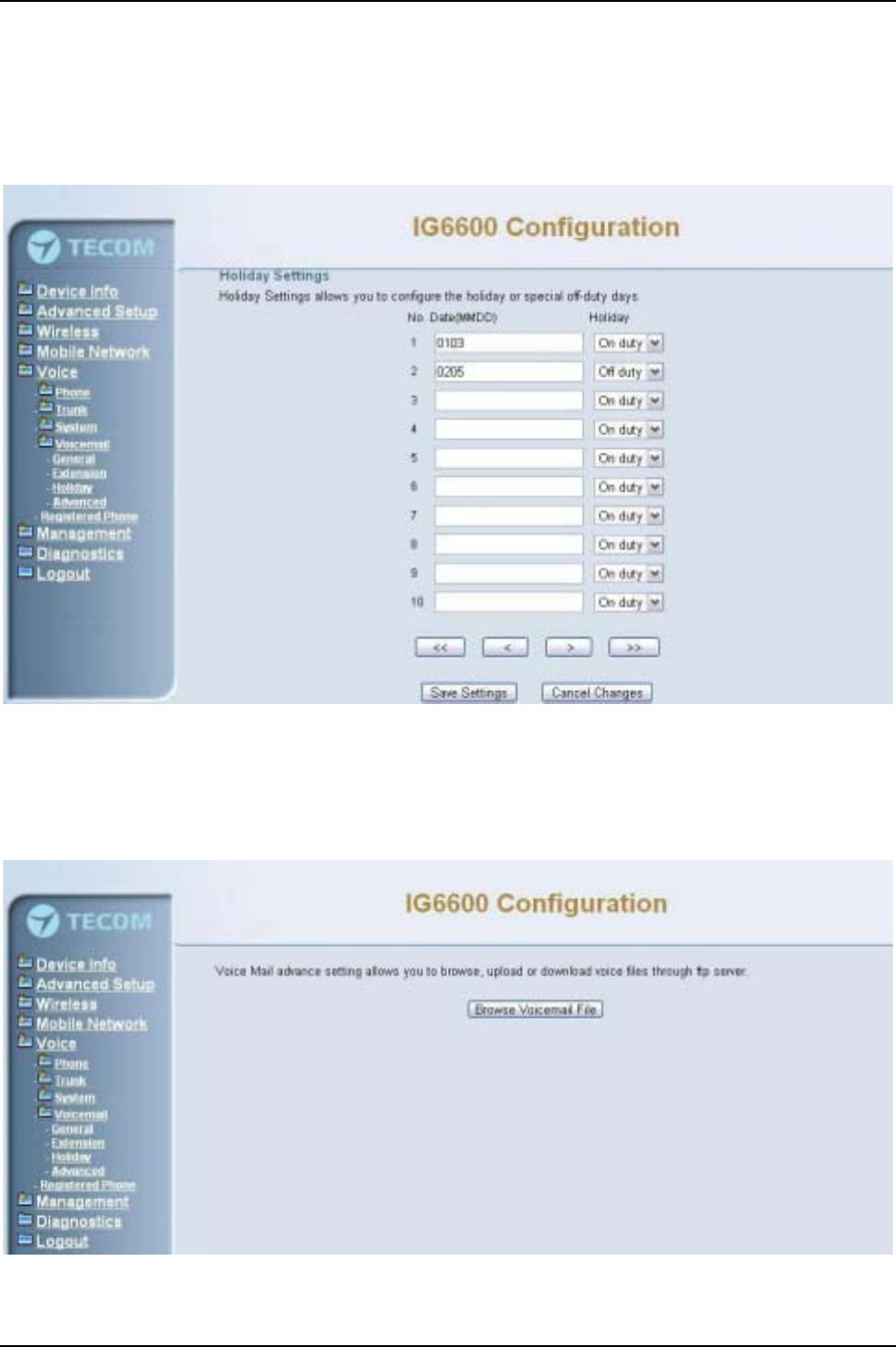
IG6600 Administration Manual
Page 98 of 139
Figure 6-90. Voice –Voice Mail –Extension –Extension Configuration
6.7.4.3 Holiday
This page allows you to configure the holiday or special off-duty days. You can click the
buttons under the table to choose pages. (Figure 6-91)
Figure 6-91. Voice –Voice Mail –Holiday
6.7.4.4 Advanced
This page allows you to browse, upload or download voice files through IG6600’s ftp
server. (Figure 6-92)
Figure 6-92. Voice –Voice Mail –Advanced
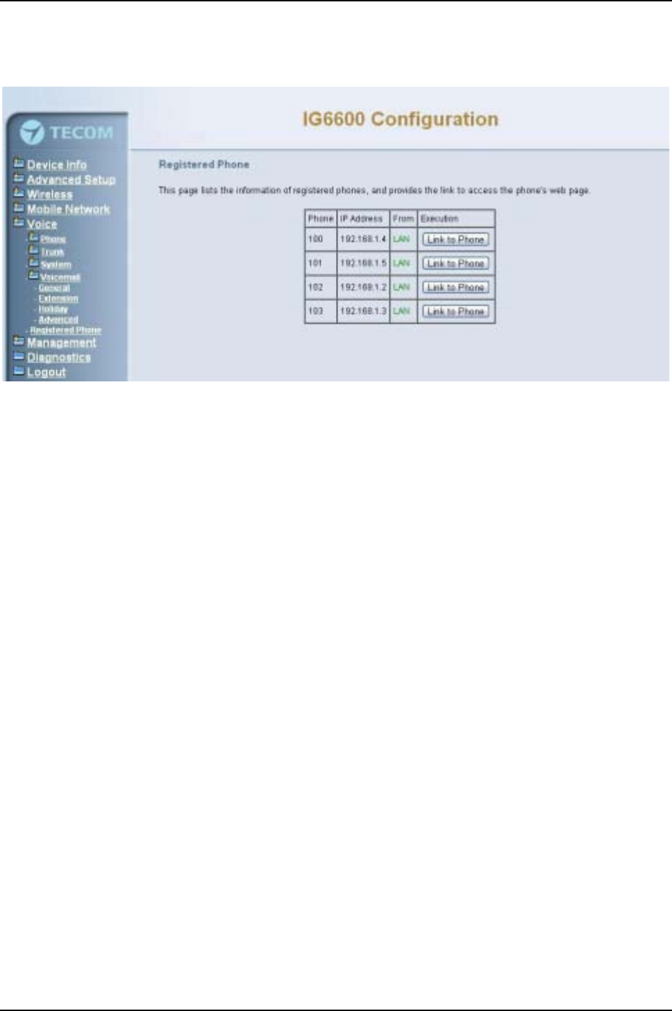
IG6600 Administration Manual
Page 99 of 139
6.7.5 Registered Phone
This page lists the information of registered phones, and provides the link to access the
phone's web page. (Figure 6-93)
Figure 6-93. Voice –Registered Phone
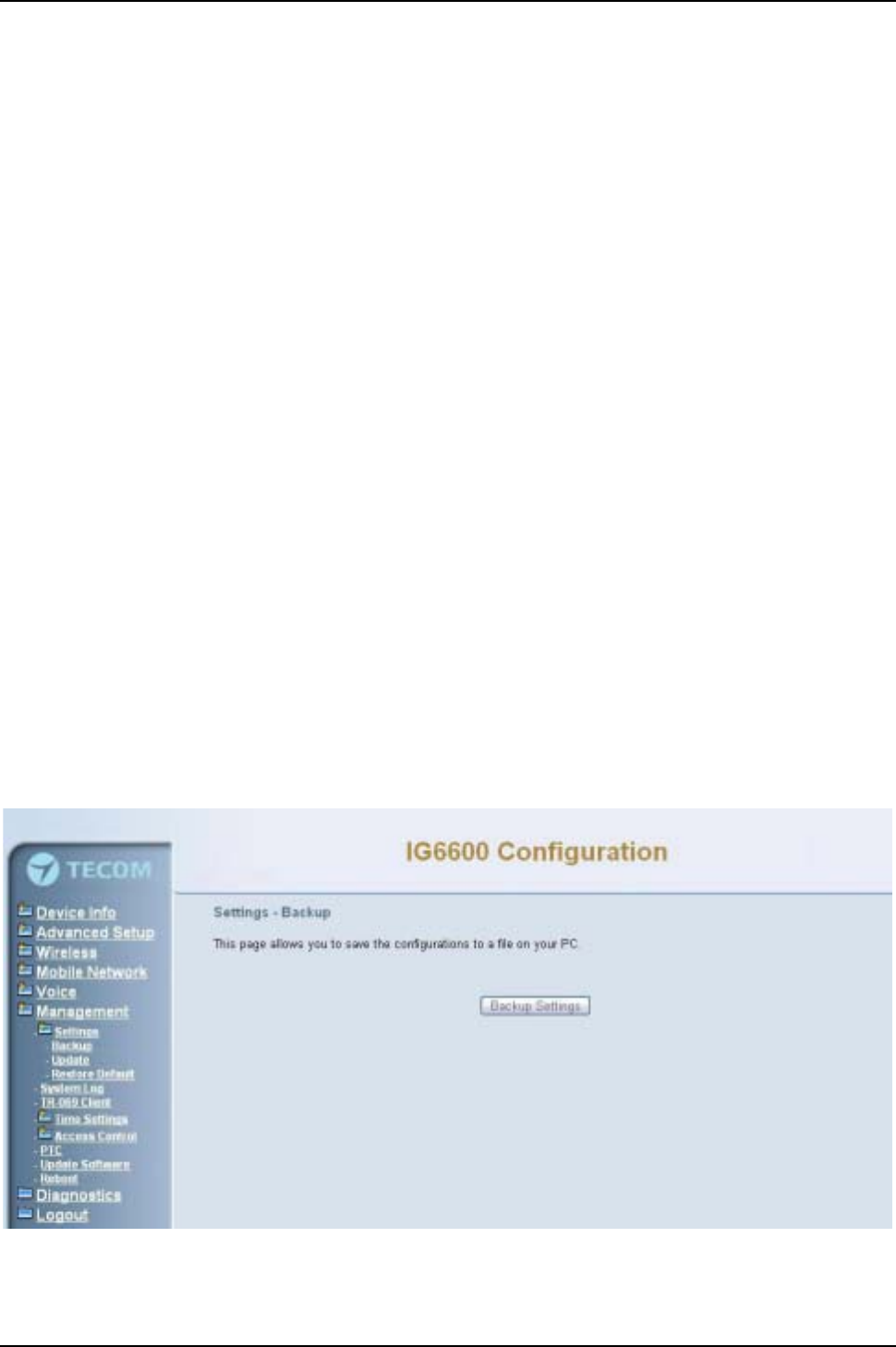
IG6600 Administration Manual
Page 100 of 139
6.8 Management
The system administrator can do the following functions to manage the configurations,
events, and software update of the IG6600.
zSettings
-Backup
-Update
-Restore Default
zSystem Log
zTR-069 Client
zTime Settings
-Internet Time
-Daylight Saving Time
zAccess Control
-Web Port
-Password
zUpdate Software
zReboot
6.8.1 Settings
System Administrator can Backup and Update the IG6600’s settings. The settings can
be saved from IG6600 to PC. The saved setting file can also be loaded from PC to
IG6600. These functions can help the system administrator to manage large amount of
IG6600s efficiently. Restore Default would set the IG6600 with the factory default
configuration.
6.8.1.1 Backup
Click “Backup Settings”, you may save your IG6600’s configurations to a file on your PC.
(Figure 6-94)
Figure 6-94. Management –Settings –Backup
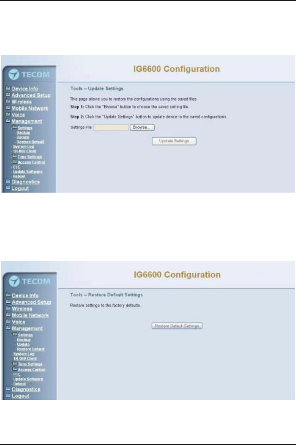
IG6600 Administration Manual
Page 101 of 139
6.8.1.2 Update
Click “Browse” to locate the setting file saved on the Local PC. Then, click “Update
Settings”would apply the settings to the IG6600 according to the configuration file.
(Figure 6-95)
Figure 6-95. Management –Settings –Update
6.8.1.3 Restore Default
Click “Restore Default Settings” to restore the factory default settings. This would be
helpful when the settings mass up. After IG6600 returns to factory default settings, the
wizard setup is invoked automatically when the administrator accesses to IG6600’sweb
server. (Figure 6-96)
Figure 6-96. Management –Settings –Restore Default
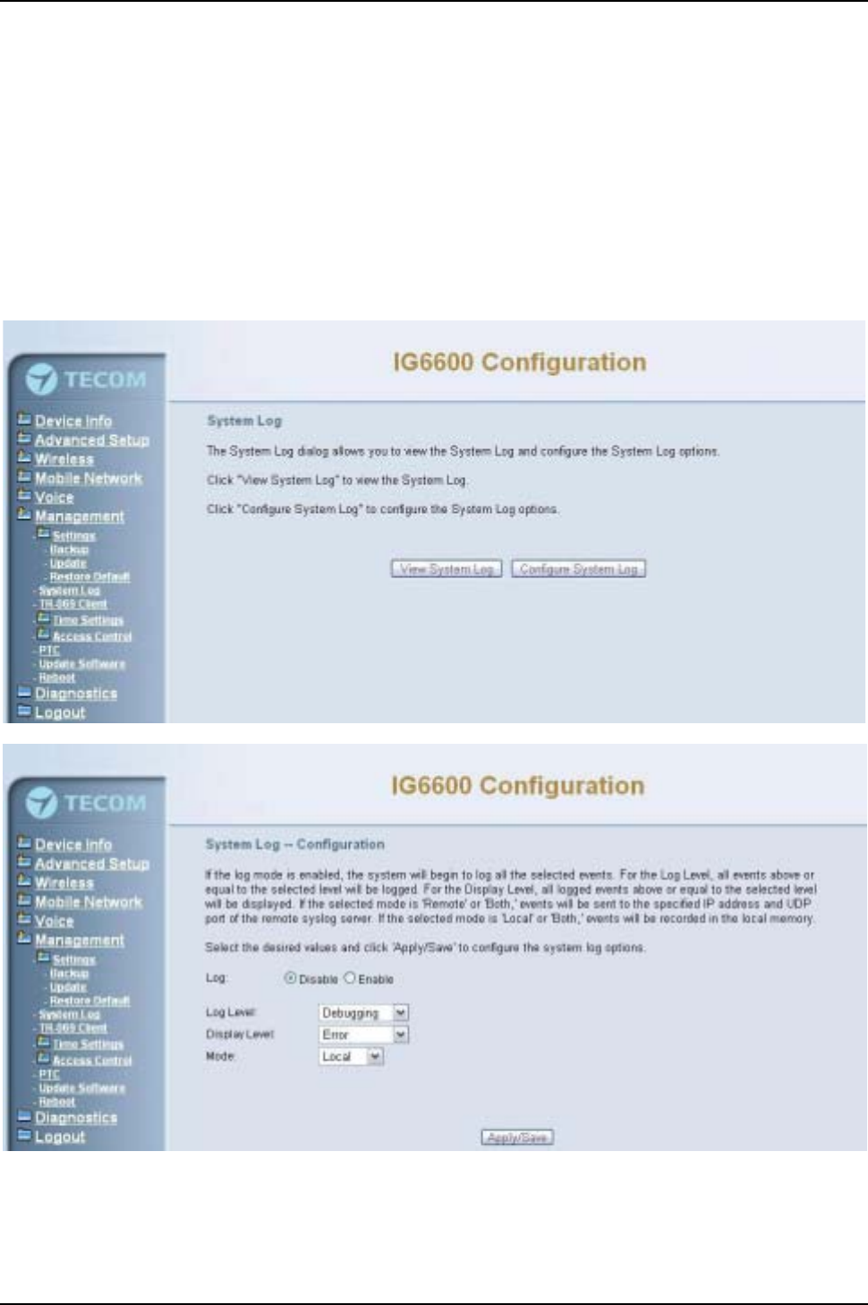
IG6600 Administration Manual
Page 102 of 139
6.8.2 System Log
This allows system administrator to view the system log and configure the system log
options. Click "View System Log" to view the system log. Click "Configure System Log"
to configure the system log options. (Figure 6-97,Figure 6-98)
When you configure the system log options, you can see Log Levels and Display Levels:
Emergency, Alert, Critical, Error, Warning, Notice, Informational, and Debugging. The
Log Level implies that what log level is applied to IG6600 to record the log. The Display
Level would just show the users the log message that they want to know. As a result,
Display Level was just a subset of total log messages. If “Mode”is set to “Remote”or
“Both”, the log messages would be sent to the specified UDP port of the specified log
server. Click “Apply/Save”button that you can save the new configuration.
Figure 6-97. Management –System Log
Figure 6-98. Management –System Log –System Log Configuration
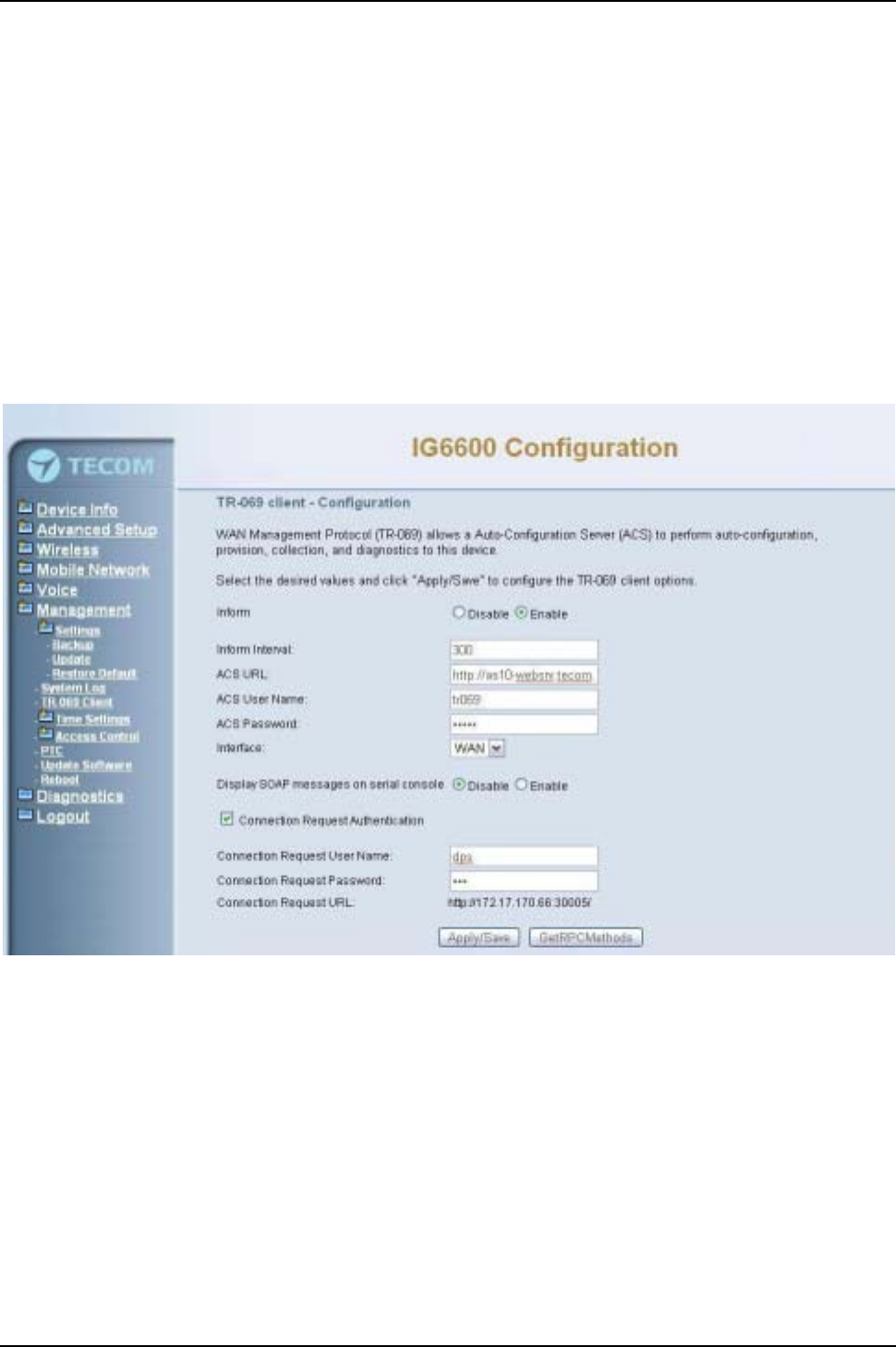
IG6600 Administration Manual
Page 103 of 139
6.8.3 TR-069 Client
WAN Management Protocol (TR-069) allows an Auto-Configuration Server (ACS) to
perform auto-configuration, provision, collection, and diagnostics to this device.
Firmware upgrade or vendor configuration file backup can be done remotely on ACS
server. Select the desired values and click "Save Settings" to configure the TR-069
client options. (Figure 6-99)
Inform: It can be set to Disable or Enable for periodically inform every Inform Interval.
Fill the correct ACS URL, ACS username/password and select Interface, the TR-069
client is able to connect to ACS server.
Display SOAP message on serial console: Disable/Enable.
Connection Request Authentication:The“Connection Request User Name”and
“Connection Request User Password”are used for the server to initiate an ACS
initiation connection.
Figure 6-99. Management –TR-069 Client
6.8.4 Time Setting
This item allows you to configure system’s time and the Daylight Saving Time.
6.8.4.1 Internet Time
This page allows you to configure the NTP time server so the IG6600 can synchronize
its system time with NTP time server automatically (Figure 6-100).
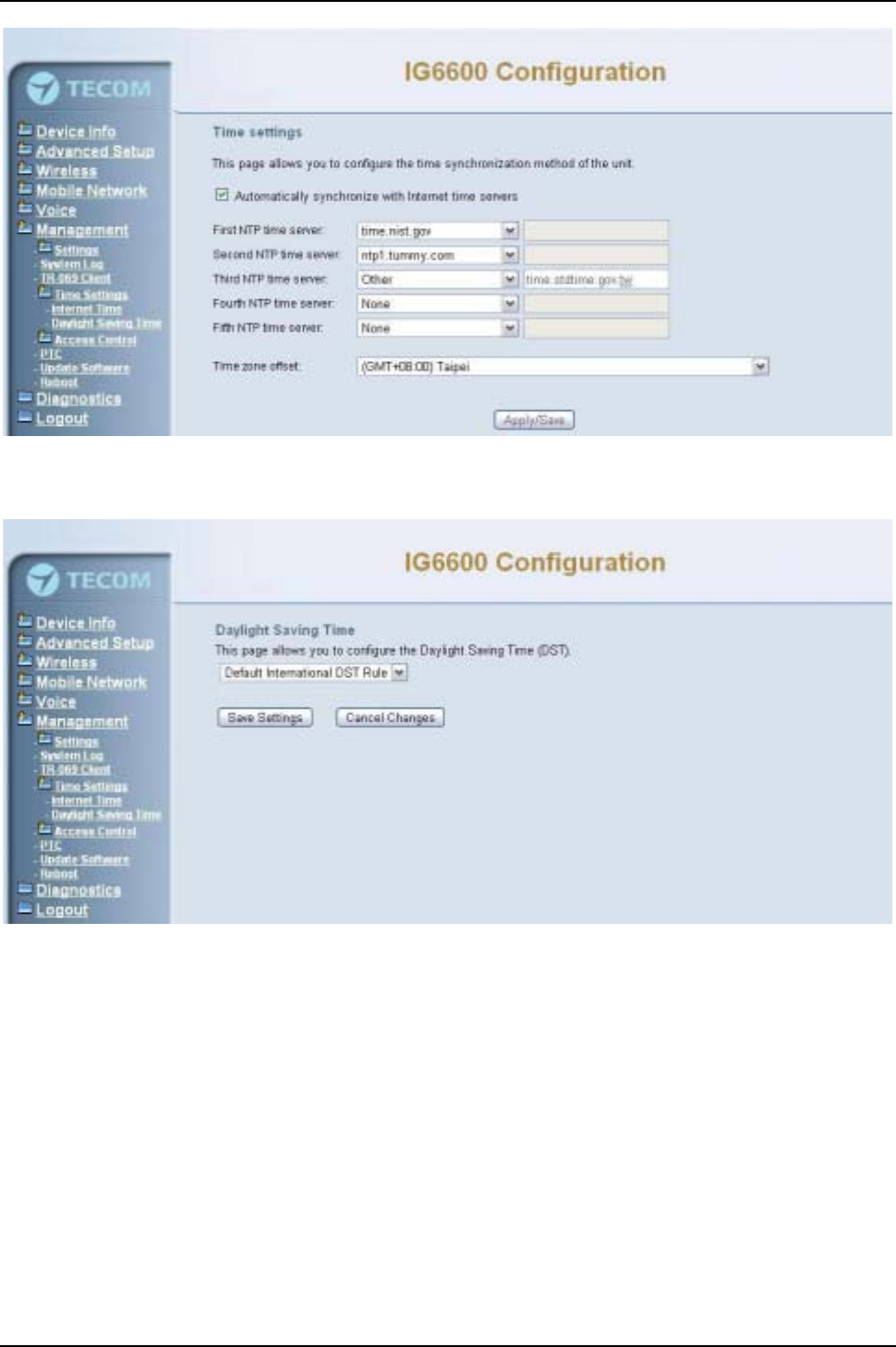
IG6600 Administration Manual
Page 104 of 139
Figure 6-100. Management –Time Setting –Internet Time –NTP setting
6.8.4.2 Daylight Saving Time
Figure 6-101. Management –Time Settings –Daylight Saving Time
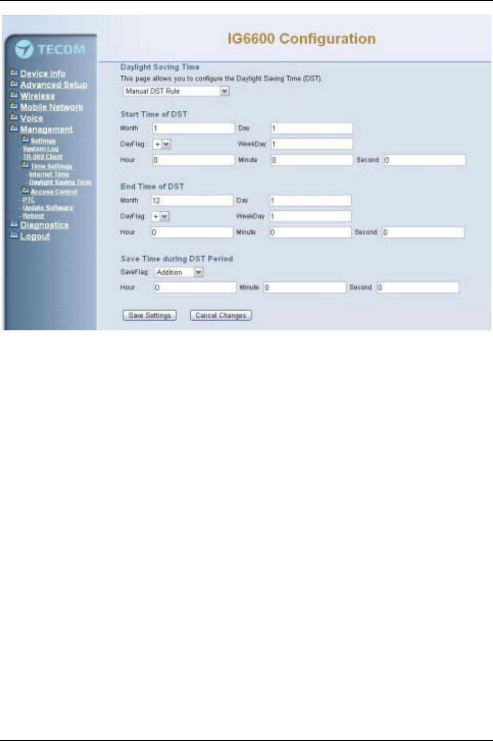
IG6600 Administration Manual
Page 105 of 139
Figure 6-102. Management –Time Settings –Day Light Saving Time –Manual DST Rule
This page allows you to configure the Daylight Saving Time (DST) which supports auto
adjustment for daylight saving time. Click “Save Settings”button that you can save the
new configuration. Click “Cancel Changes”button that you can cancel the changes.
(Figure 6-101,Figure 6-102)
Default International DST Rule:Default DST Rule obey international standard rule.
Manual DST Rule:Define your own DST Rule.
Start Time of DST: The date and time to start daylight saving.
If “Weekday”is 0, it means the date to start daylight saving is at exactly the given
date. If “Weekday”is not 0, the DST starts on the “Weekday”on or after the given
date.
End Time of DST: The date and time to end daylight saving.
If “Weekday”is 0, it means the date to end daylight saving is at exactly the given
date. If “Weekday”is not 0, the DST ends on the “Weekday”on or before the given
date.
Save Time during DST Period: The amount of hour/min/sec to add to the current
time during daylight saving period.
6.8.5 Access Control
This item allows you to configure Web Port and password for user, support, and
administrator.
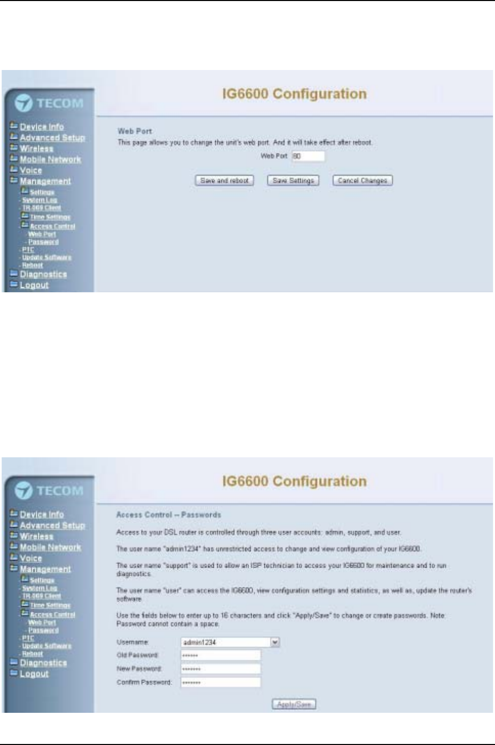
IG6600 Administration Manual
Page 106 of 139
6.8.5.1 Web Port
This page allows you to change the IG6600's web port. And it will take effect after reboot.
(Figure 6-103)
Figure 6-103. Management –Access Control –Web Port
6.8.5.2 Password
In this page you can define the passwords for administrator, support, and user. The
Administrator has unrestricted access to change and view configuration of your IG6600.
The Support is used to allow an ISP technician to access your IG6600 for maintenance
and to run diagnostics. The User can access the IG6600, view configuration settings and
statistics, as well as, update the router’s software.
Use the password field to enter up to 16 characters. Note: Password cannot contain a
space. (Figure 6-104)
Figure 6-104. Management –Access Control –Password
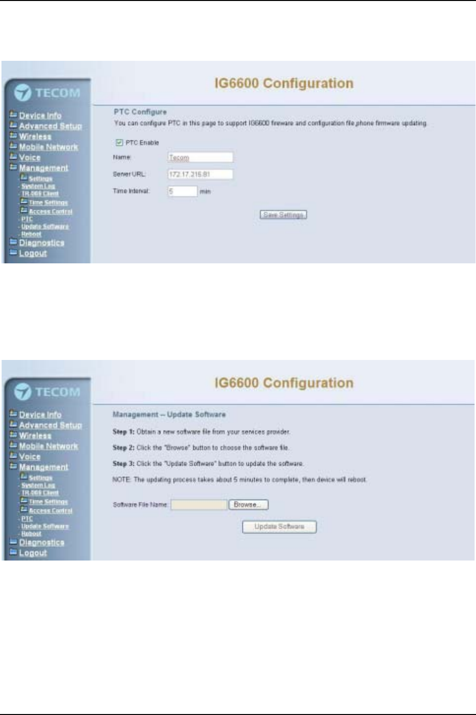
IG6600 Administration Manual
Page 107 of 139
6.8.6 PTC
IG6600 can connect to a PTS for upgrade firmware. You can configure IG6600 name,
PTS server URL and Time interval for check new firmware version. (Figure 6-105)
Figure 6-105. Management-PTC
6.8.7UpdateSoftware
The new released software could be upgraded from the Local PC side or remotely. Click
the “Browse”to locate the new software image file in the PC. Then, click “Update
Software”to process the software update. NOTE: The upgrade process takes about 5
minutes to complete, and your IG6600 will reboot. (Figure 6-106)
Figure 6-106. Management –Update Software
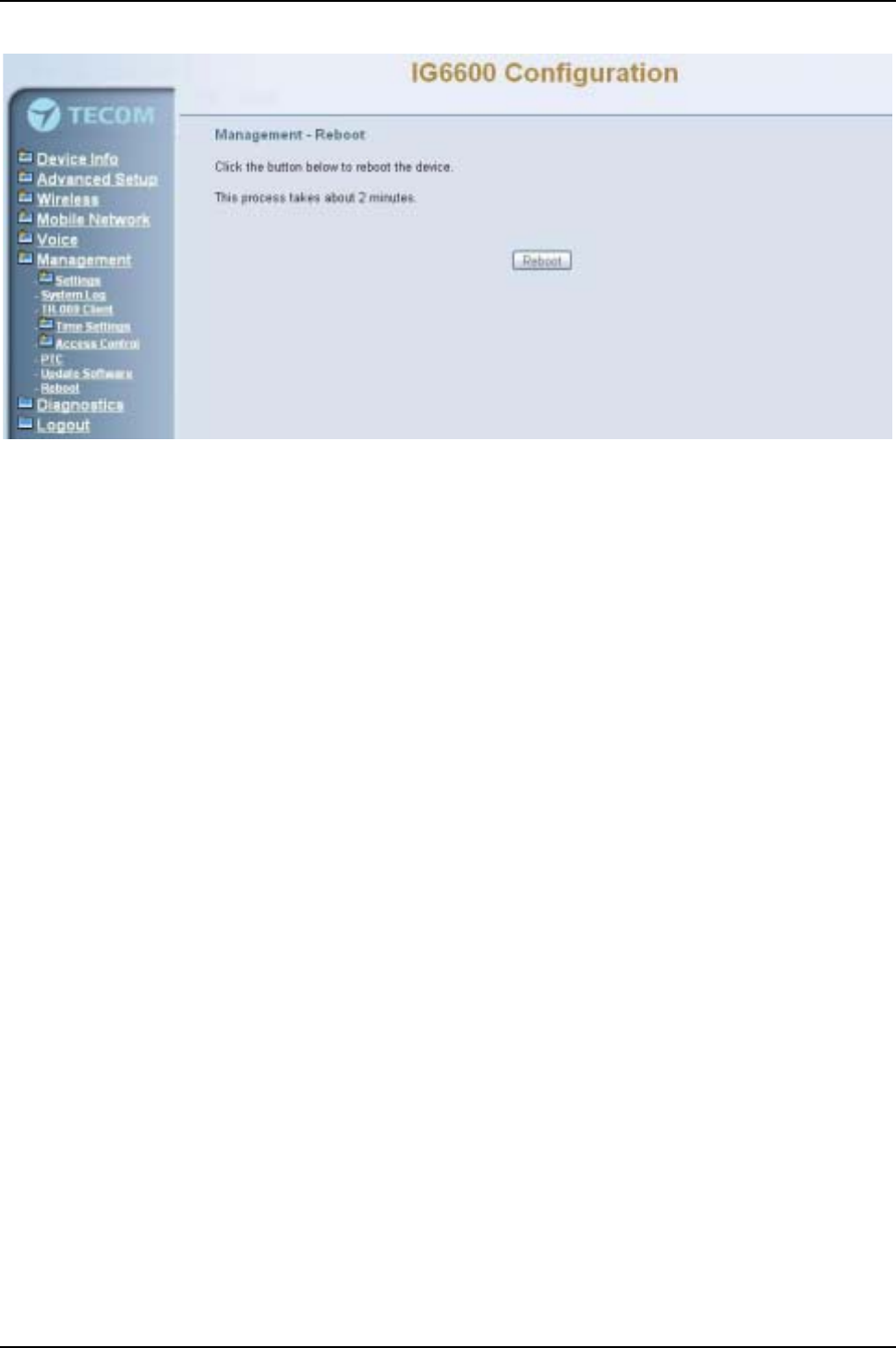
IG6600 Administration Manual
Page 108 of 139
6.8.8 Reboot
Figure 6-107. Management –Save/Reboot
Click “Reboot”to reboot the IG6600. The IG6600 would automatically save the
configuration before reboot, so that modified settings would take effect after reboot.
(Figure 6-107)
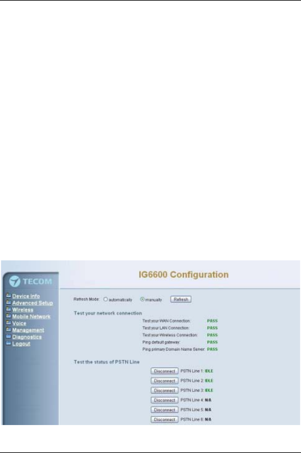
IG6600 Administration Manual
Page 109 of 139
6.9 Diagnostics
This page provides the following information to users: (Figure 6-108,Figure 6-109)
zThe network connection information on the net.
zThe status of IG6600's PSTN Line.
zThe status of IG6600’s IP Trunk Line.
zThe status of IG6600’s AA Line.
zThe status of IG6600’s FXS.
1) Network Connection
PASS: Normally connected
FAIL: Connecting fail
DOWN: No connection
2) PSTN Line / IP Trunk Line / AA / FXS
FAILED: Connecting fail or registering failure
IDLE: The line is idle
N/A: The line is not available
Busy: The line is in use
For Refresh Mode, if user select automatically refresh, the web page will automatically
refresh for every 20 seconds.
Click “Disconnect”button will allow you release the selected trunk line or rescue the
blocked one.
Figure 6-108. Diagnostics –1
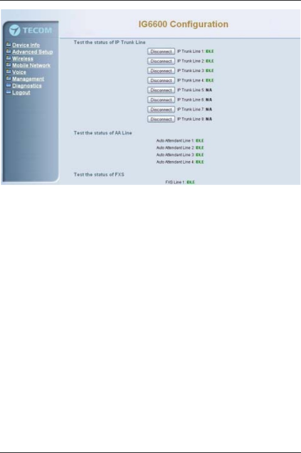
IG6600 Administration Manual
Page 110 of 139
Figure 6-109. Diagnostics –2
6.9 Logout
Press “Logout”, you can logout the IG6600 web configuration page.

IG6600 Administration Manual
Page 111 of 139
Appendix 1: Product Summary
TCP/IP Protocols
IP Protocol (791)
ARP (RFC 826) / RARP (RFC 903)
ICMP (RFC792)
TCP (RFC 793)
UDP (RFC 768)
SNTP
DNS
HTTP
Telnet
TFTP
RTP
Static Routing
NAT with ALGs
IP Address Assignment
Static
Dynamic
Subnet Mask
PPPoE Client (RFC 2516)
Primary and Secondary DNS
DHCP Server (RFC 2131-2132)
DHCP Client (RFC 2132)
Routing
RIP v1/v2
Static routing
DHCP Server/Relay/Client
DNS Relay
NAT/NAPT
Virtual Server
Virtual Server
Port Trigger
DMZ
QoS
IP ToS function (RFC 1349)
Priority queues for upstream traffic based on ToS field.
IP Precedence
Bandwidth Control
3G
3G HSDPA dongles for WAN backup and 3G interface
VoIP Protocols
SIP (RFC 3261)
SDP(RFC2327, RFC3264)
Real Time Protocol (RTP ; RFC 1889)
MD5 (RFC3261 HTTP) digest authentication
G.168 Echo Cancellation
Voice Codec: G.711u, G.711a, G726-16, G726-24, G726-32 and G.726-40 (G.729a optional)
Support FAX/modem tone detection and auto-fallback to G.711
T. 3 8

IG6600 Administration Manual
Page 112 of 139
IP Trunk
Support up to 8 IP Trunks
SIP message, including INVITE, re-INVITE, ACK, CANCEL, OPTIONS, BYE, REGISTER, INFO,
REFER, SUSCRIBE/NOTIFY and REPLACE messages.
SIP Outbound Proxy, SIP Proxy and Registrar
Auto-Registration when power-on or period
Session Timer support
Support IP address, domain name, user name, display name for SIP URL
Digital Audio
Codec: G.711 a-law/µ-law 64Kbps, G.726-16/24/32/40
SIP Call Offer /Answer: Codec auto capacity exchange
Echo Cancellation: G.168 for each voice line
Silence Detection/Suppression
Comfort Noise Generation
Adaptive jitter buffer
Different frame size support (10,20,30,40, 50, and 60ms)
Packet loss concealment
Out-band (RFC2833) and In-band DTMF
Security
Password protected system management
User authentication for PPP (PAP/CHAP/MSCHAP)
Firewall
Packet Filtering
Access Control List
Wireless Security:
Support WEP (64, 128-bit) encryption
802.1x and WPA/WAP2 authentication
MAC Address-based access control
WDS support
Configuration Management
LAN/WAN management via Telnet interface or Web-based browser interface
Firmware upgrade available by TFTP/ HTTP
Status display and event report from Web-based management
Configuration Save and Restore
Reset to factory default
Radio - WLAN
Standard : IEEE 802.11b/g/n
Media Access Control : CSMA/CA with ACK
Modulation : OFDM/CCK
Frequency Range (Range depends on different country)
Remote Diagnostic
Syslog
Device Diagnostic, Enable remote test following:
Test the connection to your local network,
The connection to your Internet service provider,
The status of PSTN Line,
The status of IP Trunk Line,
The status of VAA Line,
The status of FXS
Physical Interfaces
One 10/100/1000BaseT Ethernet port (RJ-45) for WAN interface
One 10/100BaseT Ethernet port (RJ-45) for LAN interface

IG6600 Administration Manual
Page 113 of 139
One Telephone interface (RJ-11)
Six PSTN Line interface (RJ-11)
One USB Host interface
LED Status
LED Name Color Status Description
Red On Firmware updating
Blue Flashing System booting up
Blue On System initialized and running
POWER Red/Blue
Off Power off
On Wireless LAN is activeWIRELESS Blue
Off Wireless LAN is idle
Off PSTN Line is idleLINE (1-6) Blue
On PSTN Line is active
Off Phone is idleTEL Blue
On Phone is active
On LAN is connected
Off LAN is not connected
LAN Blue
Flashing LAN activity present (traffic in either
direction)
Blue On WAN is connected and IP is obtained
Red On WAN is not conneced or no IP assigned
WAN Red/Blue
Flashing WAN activity present (traffic in either
direction)
Power Requirement
Input : Voltage Range 90~230 VAC
Output : 12V DC / 1.5A
Operating Environment
Temperature : 0~40
Humidity : 10 to 90%, non-condensing
Physical Specification
Dimension : 190(W) x 280(L) x 34(D) (mm)

IG6600 Administration Manual
Page 114 of 139
Appendix 2: Feature Access Codes
The Feature Access Codes are applied in Tecom IP2032/2061/2062 Phones and FXS
phone only. It’s to activate/cancel some IG6600 user-specified functions.
These Feature Access Codes are used when the phone is at idle state.
Direct Call Forward
Forward all of the calls without regard to the extension status.
(Type: 0 – ICM, 1 – Outside, 2 –Both)
To Activate
*21 + Type + Ext/VAA/ICD No.
*21 + Type + * + (PSWD) + * + Outside Number
To Cancel
**21
Busy Call Forward
Forward the calls if the extension is busy.
(Type: 0 – ICM, 1 – Outside, 2 –Both)
To Activate
*22 + Type + Ext/VAA/ICD No.
*22 + Type + * + (PSWD) + * + Outside Number
To Cancel
**22
No Answer Call Forward
Forward the calls if the extension doesn't answer the call within No Answer Time.
(Type: 0 – ICM, 1 – Outside, 2 –Both)
To Activate
*23 + Type + Ext/VAA/ICD No + * + Time.
*23 + Type + * + (PSWD) + * + Outside Number + * + Time.
To Cancel
**23
DND Call Forward
Forward the calls if the extension enables DND.
(Type: 0 – ICM, 1 – Outside, 2 –Both)
To Activate
*24 + Type + Ext/VAA/ICD No
*24 + Type + * + (PSWD) + * + Outside Number
To Cancel
**24
Follow Me Call Forward:
Forwards calls at your extension to the extension where you are currently working.
(Type: 0 – ICM, 1 – Outside, 2 –Both)

IG6600 Administration Manual
Page 115 of 139
To Activate
*25+Type+ExtNo+*+Password
To Cancel
To disable, dial **25 + Ext No + * + Password
Call Fork
When extension gets an incoming call, the extension gets ringing. It rings another
extension or rings an outside destination simultaneously.
(Type: 0 – ICM; 1 – Outside; 2 –Both)
To Activate
*26 + Type + Ext No
*26 + Type + * + (PSWD) + * + Outside Number
To Cancel
**26
Do Not Disturb
Extension users can enable DND to stop incoming calls from ringing at their phone.
To Activate
*4
To Cancel
**4
Call Pickup
Users can answer the calls at another extension. The feature allows you to easily
access calls ringing via the feature access code.
*53 + Ext No.
COS Following
It changes the individual COS of the extension temporarily.
*55 + (phone number) + (password)
Call Back Busy (for IP20xx only)
When remote party is busy, press 6 to wait call back. Press **66 to delete the record.
To Activate
6
To Cancel
*66
Reset Feature Buttons
Reset all feature buttons to IG6600’s setting.
*68 + (Password)
Reset To Default
Selected IG6600 extension features can be returned to default setting.
*69+(password)

IG6600 Administration Manual
Page 116 of 139
Feature Key Programming
To program the line keys as a PSTN, IP Trunk, Trunk Group number, Call-Park number
or Extension number.
*70 + (Feature Key number: 01 –28(*)) + (PSTN, IP Trunk, Trunk Group number,
Call-Park number or Extension number)
Note: IP2032 provides 2 keys for feature access.
IP2062 provides 4 keys for feature access.
IP2061 supports EDM module, it provides 24 more (total 28) keys for feature
access.
Service Mode Selection
Change Service Mode from Operator
*79 + (Service Mode, 1 –3) + (password)
(Service Mode:
1: Day Mode
2: Night Mode
3: Time Mode)
Agent Log On/Off
It can control the status in an ICD group.
To Activate (Log On)
*91
To Cancel (Log Off)
**91
Phone Lock/Unlock
You can use the Lock feature to prevent unauthorized trunk calls from being made from
extension.
To Activate Phone Lock
*97 + (password)
To Cancel Phone Lock
**97 + (password)
Call Waiting
If disabled, it returns busy response while getting second call at non-idle state
To Activate
*98
To Cancel
**98
Page Allow/Deny
Block one-way paging (group and all page) over the IP phone speaker
To Activate Page Deny

IG6600 Administration Manual
Page 117 of 139
*99
To Cancel Page Deny
**99

IG6600 Administration Manual
Page 118 of 139
Appendix 3: Auto Attendant and Voicemail System
Appendix 3.1 System Voice Prompts
Appendix 3.1.1 Preset Voice Prompts
IG6600 provides two languages service for the all voice files. The all files are saved in vox folder in
PCM u-law format. The only difference of the file name in the both languages is the leading digit of
the file name. It’s“1”for the first language, “2”for the second language.
File# Contents Application
10001 Hello, please dial the extension number directly or
press zero for the operator
It’s a Welcome Message. It’s played while getting an
incoming FXO/IP line call in working hours.
10002 Hello, it is out of the office hours, please dial the
extension number directly or press zero for the
operator
It’s a Welcome Message. It’s played while getting an
incoming FXO/IP line call in off hours.
10003 Hello, it is lunch time, please dial the extension
number directly or press zero for the operator
It’s a Welcome Message. It’s played while getting an
incoming FXO/IP line call in lunch hours.
10004 Hello, today is holiday, please dial the extension
number directly or press zero for the operator
It’s a Welcome Message. It’s played while getting an
incoming FXO/IP line call in holidays.
10051 Please dial the phone number, at the end, press
pound key (#)
It requests to dial a phone number.
10097 This mailbox's capacity is used. There is no room
for more messages.
IttalkstotheCallerithasnoroomtostoretheleaving
messages.
10102 The number is incorrect, your call will be
transferred to the operator
AA gets non-existed extension number input many
times. AA will transfer the call to Operator.
10103 The number is incorrect It’s played while the user makes an incorrect input
10104 Please check your number and dial again It’s played before AA hangs up the call.
10106 The number is incorrect, please dial again AA gets non-existed extension number input and
allows the caller to redial.
10107 The number is incorrect, Please check your
number and dial again, bye bye!
AA gets non-existed extension number input many
times. AA will drop the call.
10201 Your call is in transferring, please wait It’s played before AA transfers the call to the
transferred party.
10205 The extension line is busy, to wait for a retry,
please press the star key (*)
The transferred destination is busy. AA provides some
choices for the user.
10206 The number you dialed is not available, to wait for
aretry,pleasepress thestarkey(*)
The transferred destination doesn’t answer the call in
30 seconds. AA provides some choices for the user.
10207 To leave a message, press the pound key (#) Same as 10205 or 10206, another choice.
10210 To dial another number, press zero for the operator Same as 10205 or 10206, another choice
10212 The number you dial is not answered, to wait or a
retry, please press the star key (*)
10221 Sorry, the number you dialed is not available,
please dial another number, or press zero for the
operator
It’s played while transferring a call to an extension set
“Reject”of dial in.
10301 Please leave your message after the beep, when
finish, press the pound (#)
It reminds the user how to leave messages.
10302 Your message has been recoded Finish leaving message.
10303 To confirm recording, press one
To listening to your record, press two
To record your message again, press three
To cancel your recording, press four
When finishing, press the pound (#)
It’s played after finishing leaving message.
10304 Your message has been saved The leaving message is recorded.
10305 End of messages Notity that all leaving messages are played
10306 Thanks for your using, goodbye It’s played while finishing Voicemail System service.
10501 Please input mailbox number It’s played first while the user gets into Voice Mail Box
through the FXO/IP trunks.
10502 Sorry, no such a mailbox number, please try again It’s played if the user dials an invalid mailbox ID..

IG6600 Administration Manual
Page 119 of 139
10503 The mailbox has not enabled, please dial another
number
It’s played if the user dials a valid, but disabled mailbox
ID.
10504 Please input your password It requests the user to enter the password of the
mailbox.
10505 The password is incorrect, please try again The user dials an incorrect password. It allows the user
to try again.
10506 The password is incorrect, please check it and try
later
The user dials incorrect password over 3 times. It
disallows the user to try again.
10507 To listen to the message, press one
To delete all messages, press two
To record your personal greeting, press three
To change the password, press four
It’s played after entering Voice Mail Box.
10510 You have no messages No leaving message in the mailbox.
10511 You have It will report how many leaving messages in the
mailbox.
10512 messages It reports how many leaving messages in the mailbox.
"xx messages"
10513 message "x message"
10515 new
10516 To listen to this message again, press one
To listen to next message, press two
To delete this message, press three
To transfer this message to another mailbox, press
four
To listen to the previous message, press five
When finish, press the pound key (#)
This message is played when user dial a digit other
than 1~5 and # during message listening.
10517 This is the last message It’s played if it has played the all messages.
10518 To confirm the deletion, press star (*)
10519 This is the first message It’s played if user order playback previous message
when it has played the first message.
10521 You message has been transferred successfully Transfer the leaving message to another mailbox well.
10522 Transferring failed Fail to transfer the leaving message to another
mailbox.
10523 Deleting, please wait Voicemail system is deleting the all leaving messages.
10524 All messages are deleted All leaving message are deleted.
10526 Please input new four digits number password It reminds the user how to input the new mailbox
password.
10527 The new password you entered is It plays what the new input password is.
10528 To confirm the new input, press one
To re-enter, press two
To cancel and return to the previous menu, press
the pound (#)
It’s to ask whether the new input password is correct.
10529 Your password has been changed It’s to report the password is changed successfully.
10531 To listen to your greeting, press one
To record new greeting, press two
To delete the current greeting, press three
When finish, press the pound (#)
It’s for recording a user’s temporally greeting.
10532 You have no greeting recorded It’s played if having no greeting message.
10533 Please record greeting after the beep. When finish,
press the pound (#)
It reminds the user how to record the greeting
message.
10534 Your recording is finished It’s played after finishing recording.
10547 The setting is completed Finish setup.
10549 Deletion completed It reports the leaving message is deleted successfully.
10550 Deletion failed It fails to delete the leaving message.
10580 Sorry, the mailbox is in use The mailbox is in use.
10601 Please begin to record after the beep, when finish,
press the pound (#)
It reminds the administrator how to record the voice
files.
10731 AM ante meridiem
10732 PM post meridiem
10733 Oh Zero. Ex. February 3rd two oh two a.m. (Feb 03 2:02
a.m. = 2:02 )
19001 Please input the administrator password It requests administrator to enter the mailbox

IG6600 Administration Manual
Page 120 of 139
password.
19011 To record the first language greeting, press one
To record the second language greeting, press two
When finish, press the pound (#)
It’s for recording system greeting message.
19012 To record the greeting for regular office hours,
press one
To record the greeting for out of office hours, press
two
To record the greeting for lunch time break, press
three
To record the greeting for holidays, press four
When finish, press the pound (#)
It’s to choose what kind of greeting message will be
recorded.
19013 To listen to current voice file, press one
To record the voice file, press two
When finished, press the pound (#)
It’s for recording voice files.
19015 There are no recording The voice message is not yet recorded.
19073 The extension number that you entered is not
installed in this system
It plays if entering a wrong extension number.
19200 Please input five digits number voice code.
To cancel the input, please press the pound (#)
It’s for entering voice file name.
19201 The voice file code you entered is It’stoplaywhatvoicefilenameisentered.
91000 For Language one, press one. For Language two,
press two
If setting “Two Languages”,it’s played before Welcome
message.
91100 Beep It’s played before recording any message.
pcmudial Dial Tone - PCMU
pcmadial Dial Tone - PCMA
g729dial Dial Tone - G729
g726dial Dial Tone - G726
pcmurb Ringback Tone - PCMU
pcmarb Ringback Tone - PCMA
g729rb Ringback Tone - G729
g726rb Ringback Tone - G726
mohpcmu Music On Hold - PCMU
mohpcma Music On Hold - PCMA
mohg729 Music On Hold - G729
mohg726 Music On Hold - G726
10870 0 zero 10871 1 one 10872 2 two 10873 3 three
10874 4 four 10875 5 five 10876 6 six 10877 7 seven
10878 8 eight 10879 9 nine 10880 10 ten 10881 11 eleven
10882 12 twelve 10883 13 thirteen 10884 14 fourteen 10885 15 fifteen
10886 16 sixteen 10887 17 seventeen 10888 18 eighteen 10889 19 nineteen
10890 20 twenty 10891 30 thirty 10892 40 forty 10893 50 fifty
10894 60 sixty 10895 70 seventy 10896 80 eighty 10897 90 ninety
10700 first 10701 second 10702 third 10703 fourth
10704 fifth 10705 sixth 10706 seventh 10707 eighth
10708 ninth 10709 tenth 10710 eleventh 10711 twelfth
10712 thirteenth 10713 fourteenth 10714 fifteenth 10715 sixteenth
10716 seventeenth 10717 eighteenth 10718 nineteenth 10719 twentieth

IG6600 Administration Manual
Page 121 of 139
10720 21th 10721 22th 10722 23th 10723 24th
10724 25th 10725 26th 10726 27th 10727 28th
10728 29th 10729 30th 10730 31th
10760 January 10761 February 10762 March 10763 April
10764 May 10765 June 10766 July 10767 August
10768 September 10769 October 10770 November 10771 December
Appendix 3.1.2 Voice Prompts Recording
You can change Voice Prompts by two ways:
Appendix 3.1.2.1 Through IP Phone Client
a. Use IP phone which is an extension of IG6600, dial Voicemail Directory Number (“100”at
default).
b. Type in password of the extension. (“0000”at default).
c. Press "*" key right here, to enter the Administrator mode.
d. Type in Voicemail Administrator password (“000000”at default).
e. Listen to the prompt, press "1" to record the first language greeting (File 10001 –10004).
Press "2" to record the second language greeting (File 20001 –20004).
f. Or press "3" directly, then type 5 digits file number to directly record prompt/greeting into
the respective file name. (see Appendix 2.2.4.2)
Appendix 3.1.2.2 Through FTP Server directly
a. All prompt/greeting files are saved in vox folder in PCM u-law format. You can record your
prompt in wav format first and then convert to PCM u-law. There are many free audio
convert software on the internet.
b. Login IG6600 embedded FTP serve: ftp://IG6600 IP address. (Or in IG6600-Web, select
“Voice”–“Voicemail”–“Advanced”, then press “Browser Voicemail file”button.). The voice
files are in /vm/Vox.
c. Save the new prompt to vox folder with the same file number to replace the old prompt.
(Suggest you to save all old prompts before updating the new files.)
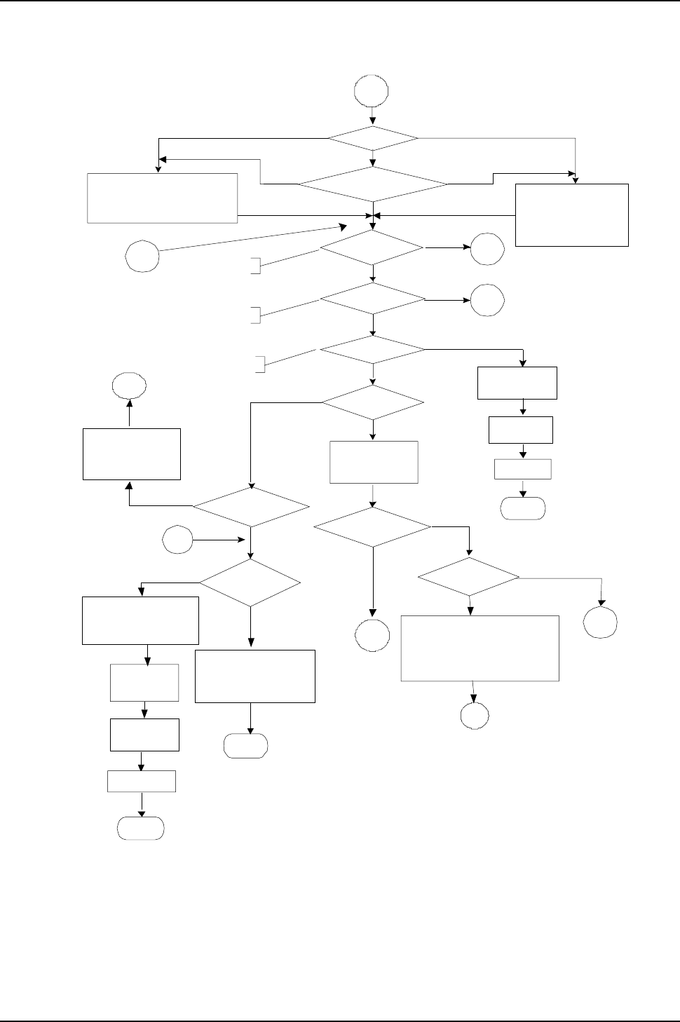
IG6600 Administration Manual
Page 122 of 139
Appendix 3.2 Flowchart
Appendix 3.2.1 Automated Attendant
Operators code?Yes
No
Press 0
Extension number
Length?
End
10306
Thanks for your using,
good bye. ,
No
Yes
1
Find out operator
number
10201
Your call is in
transferring,
Please wait
Yes
10102 ,
The number is incorrect,
your call will be transfer to
the operator
Transfer to
operator
Find out
operator
number
1A
No
Yes
10106
The number is
incorrect, please
dial again.
Make an outside call? 11
Yes
No
Press #
Listenin
g
message ? 3
Yes
No
Press *
Transfer to
operator
Extension exists?
Yes
No
No
1A
Hang up
End
Hang up
End
2
10001
Hello, please dial the
extension number directly or
presszero for the operator
19073+10210
The extension number that you
entered is not installed in this
system. To dial another number,
press zero for the operator
Error Times=Max
Try Time
Error Times=Max
Try Time
Action When Max
Error Reached
Forward to
Operator
Disconnect
1A
2
120001
Hello, please dial the
extension number
directly or press zero
for the operator
Prompt Language
Both
91000
For Language one, press one
For Language two, press two
Language 1 only Language 2 only
1B
1B
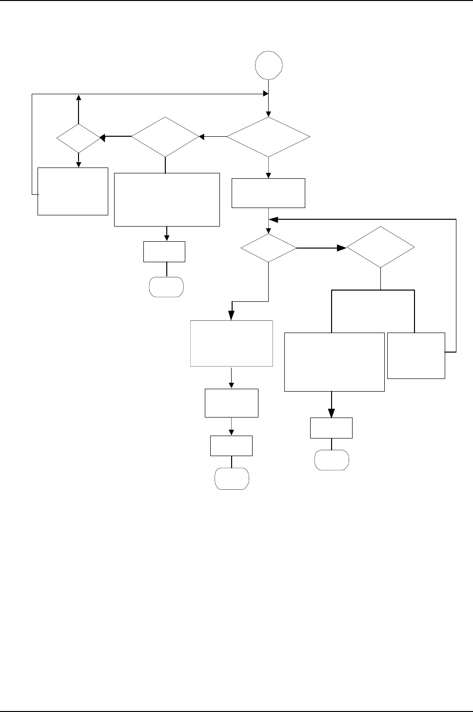
IG6600 Administration Manual
Page 123 of 139
Appendix 3.2.1.1 Make an Outside Call
10504
Please input your
password
Is password
correct?
10501
Please input mailbox
number
10502
Sorry, no such a
mailbox number,
please try again
Yes
No
Hang up
End
Yes
No
11
Yes No
10505
The password
is incorrect,
please try
again
Transfer to
destination
End
Hang up
End
Hang up
Error Times=3
Error Times=Max
Try Time
10104+10306
Please check your number
and dial again. Thanks for
your using, good bye.
10506+10306
The password is
incorrect, please check it
and try later. Thanks for
your using, good bye.
Input
number?
No
Yes
10051
Please dial the phone
number, at the end,
press pound key (#)
Exist
Not exist
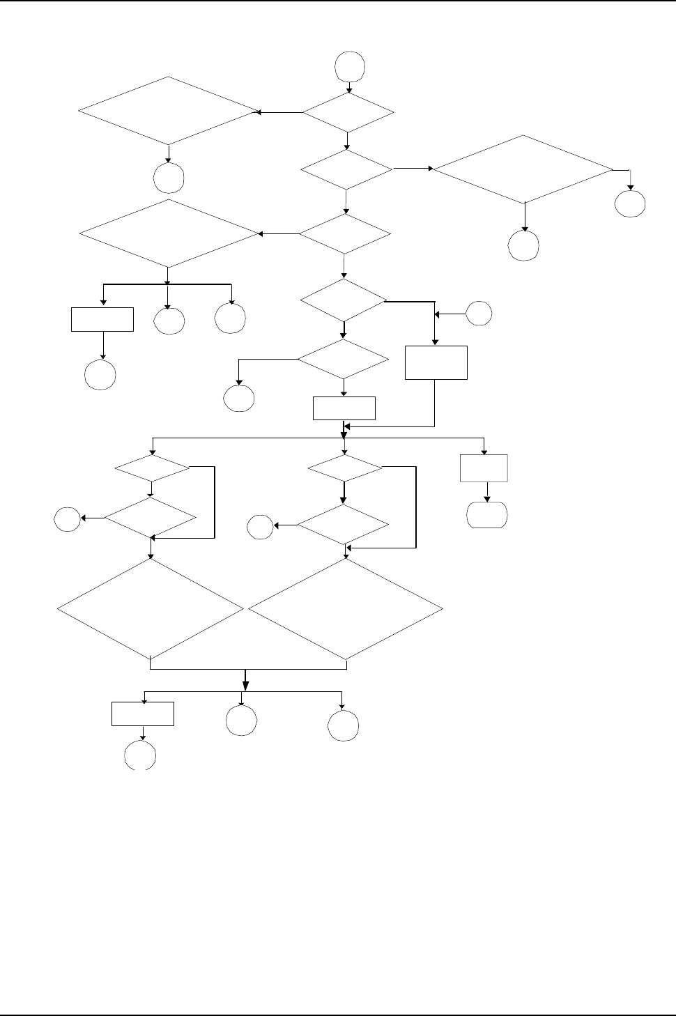
IG6600 Administration Manual
Page 124 of 139
Appendix 3.2.2 Subscriber Voicemail Flowchart
2
No
Busy
Setting reject of
dial in
No
Yes
2A
Answer
Or
Setting direct call
forward
Setting leaving
message directly
Transfer to
extension
Transfer to
destination
extension
Yes
No Answer
Hang up
End
#Zero or another
number
2B
No
Yes
Original Ext?
Setting Busy
Call
Forward
No
2B
Yes
No
Yes
Original Ext?
Setting no answer
call forward
No
2B
Yes
*
2A 1A
Transfer to
original ext.
2
Dial Times=Max Try
Time
10221+10207
Sorry, the number you dialed is not
available, please dial another number,
or press zero for the operator
To leave a message, press the pound
key (#)
Yes
10205+10207+10210
The extension line is busy, to wait for a
retry, please press the star key (*). To
leave a message, press the pound key
(#). To dial another number, press zero
for the operator.
10206+10207+10210
The number you dialed is not available,
to wait for a retry, please press the star
key (*). To leave a message, press the
pound key (#). To dial another number,
press zero for the operator.
#
2A
Zero or another
number
1A
Extension is
non-existed
No
No
Extension busy
19073+10210
The extension number that you entered is
not installed in this system.
To dial another number, press zero for the
operator.
Zero
1A
10205+10207+10210
The extension line is busy, to wait for a
retry, please press the star key (*)
To leave a message, press the pound
key (#)
To dial another number, press zero for
the operator
Zero
1A
#
2A
Transfer to
original ext.
2
*
Yes
Yes
No
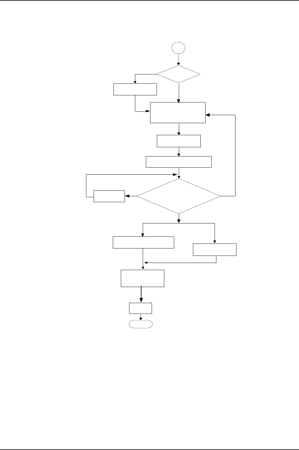
IG6600 Administration Manual
Page 125 of 139
Appendix 3.2.2.1 Leaving messages
2A
Has the personal
greeting been
recorded?
Yes
No
10301
Playing personal
greeting
Save message with
data and extension
10302
Your message has been recorded
10303
Playing the
recording
1
2
10304
Your message has been saved
3
4or #
Delete voice file of
temporary area
End
10306
Thanks for your using
good bye
Hang up Message will be recorded of caller drops the
call immediately after leaving message
Please leave your message
after the beep, when finish,
press the pound (#)
To confirm recording, press one
To listening to your record, press two
To record your message again, press three
To cancel your recording, press four
When finishing, press four
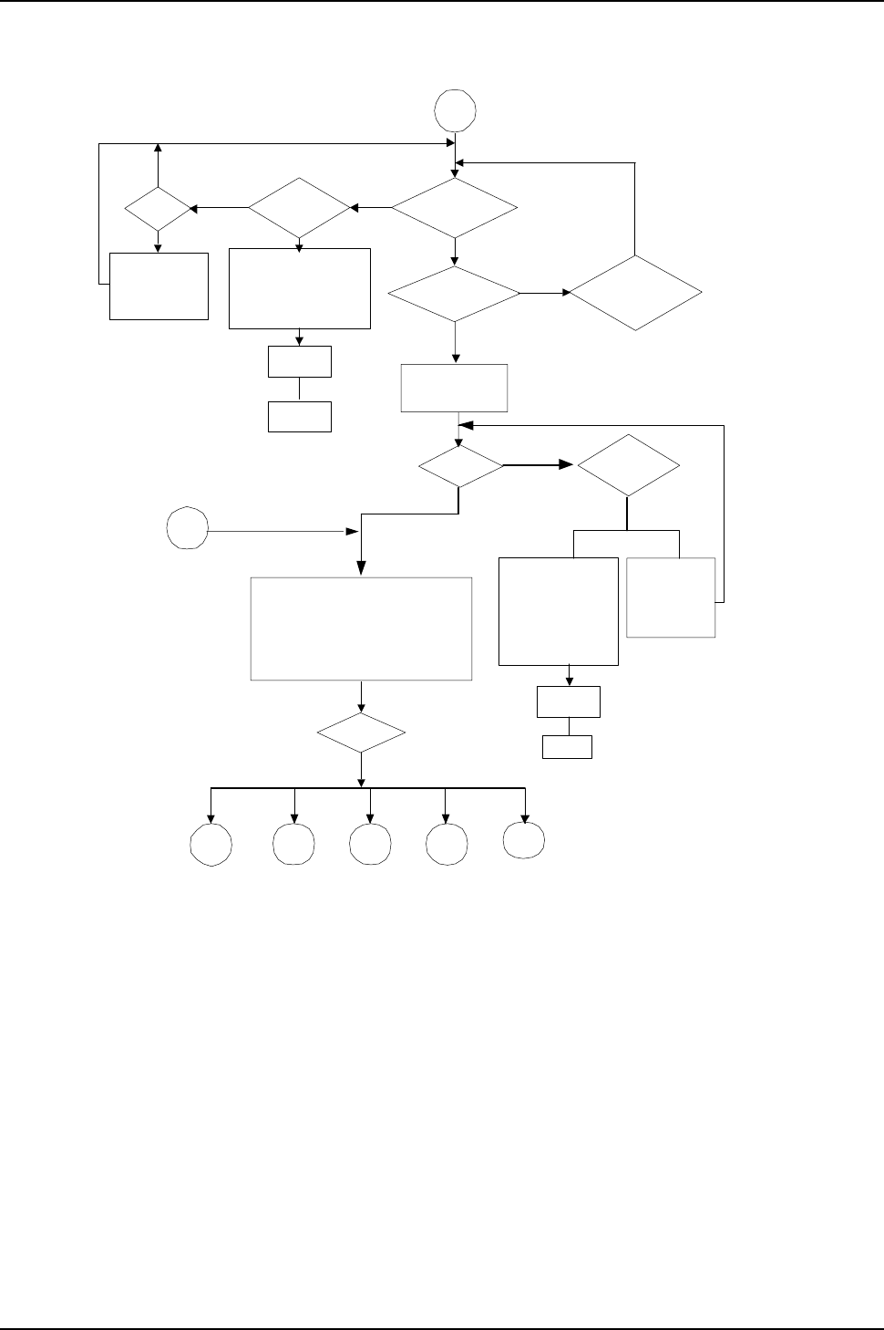
IG6600 Administration Manual
Page 126 of 139
Appendix 3.2.3 Mailbox Administer Flowchart
User input
10501
please input
mailbox
number
Yes
No
1
31
Hang up
End
Yes
No
Hang up
3
Yes No
2
32
3
33
4
34
*
4
End
10507
To listen to the message, press one.
To delete all messages, press two.
To record your personal greeting,
press three.
To change the password, press four.
10104+10306
Please check your
number and dial again.
Thanks for your using,
good bye.
Error Times=3
Sorry, no such a
mailbox number,
please try again
10502
Input
number?
No
Yes
Error Times=3
10506+10306
The password is
incorrect, please
check it and try
later. Thanks for
your using, good
bye.
Delete all messages
Record personal greeting
Change password
Administrator’sVoicemail
Listening message
3B
10505
The password
is incorrect,
please try
again.
Is password
correct?
10504
Please Input your
password
Exist
Not exist
Enable
Disable
Extension voice
mail enable or
disable?
10503
The mailbox has not
enabled, please dial
another number
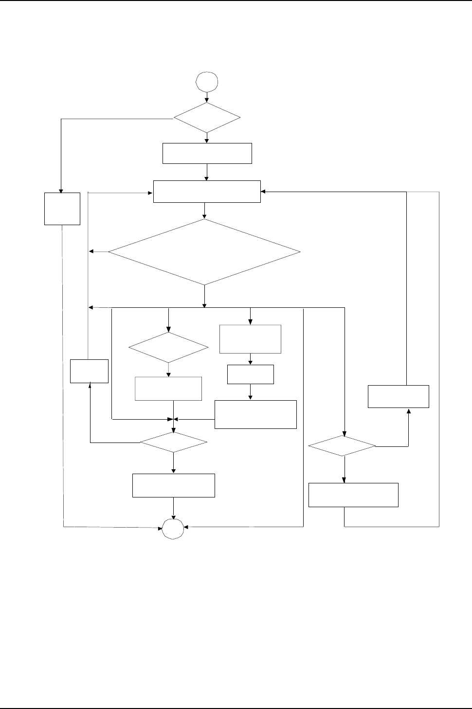
IG6600 Administration Manual
Page 127 of 139
Appendix 3.2.3.1 Listening message
31
Leaving
messages?
10510
You have
no
messages
10511 + 10512
3
10517
Point to
next
message
2
10501
4#
Yes
No
No
Yes
10549
You have ? messages
3B
Playing all voice messages and
the recording time in turns.
Press one to listen the playing message again
Press two to listen the next message
Press three to delete this message
Press four to transfer this message to other mailbox
Press five to listen the previous message
Press pound (#) to return to the previous menu
1
This is the last message
Deletion completed
Please input
mailbox number
More messages ?
10521
You message has been
transferred successfully
Transfer this
message
10518
To confirm the deletion,
press star (*)
Have previous
message?
5
1
No
Point to
previous
message
Yes
10519
This is the first message
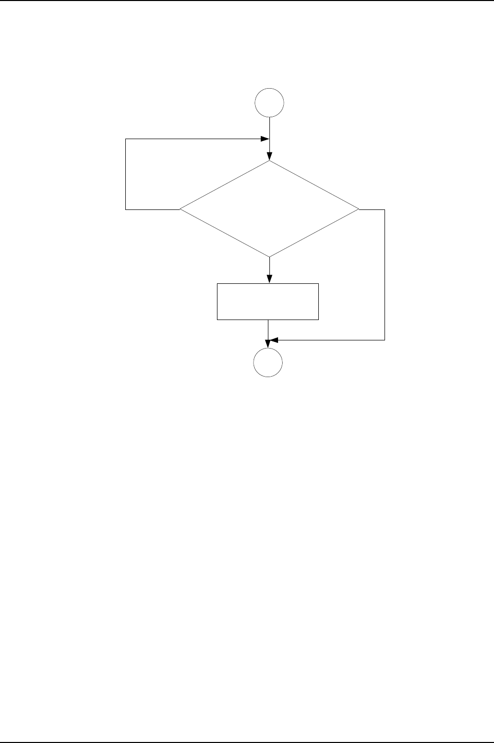
IG6600 Administration Manual
Page 128 of 139
Appendix 3.2.3.2 Deleting all Messages
32
3B
10528
To confirm the new input, press one
To reenter, press two
To cancel and return to the previous
menu, press the pound (#)
10523 + 10524
Deleting, please wait
All messages are deleted
1
2#
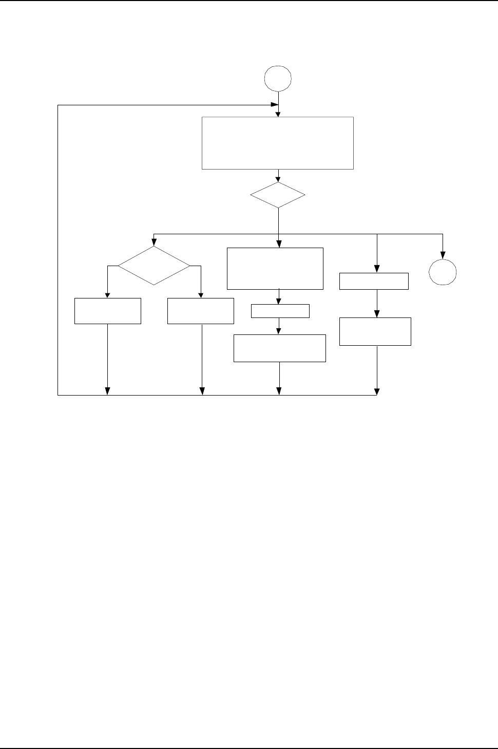
IG6600 Administration Manual
Page 129 of 139
Appendix 3.2.3.3 Recording Personal Greeting
33
10531
User input
12 #
10532
10549
3
YesNo
Playing Greeting
10533
Recordin
g
10534
To listen to your greeting, press one
To record new greeting, press two
To delete the current greeting, press three
When finish, press the pound (#)
Youhaveno
greeting recorded
Please record greeting
after the beep. When
finish, press the pound (#)
Your recording is finished
Is personal
greeting
recorded? 3B
Deletion completed
Delete message
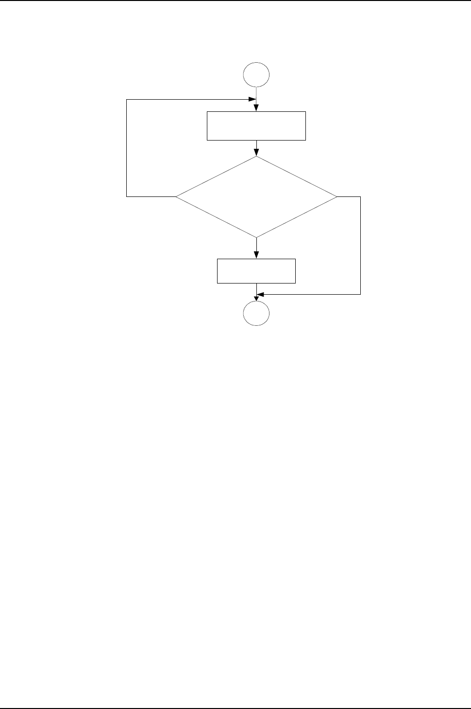
IG6600 Administration Manual
Page 130 of 139
Appendix 3.2.3.4 Changing Mailbox Password
34
3B
10526
Please input new four digits
number password
10527+10528
The new password you entered is xxxx
To confirm the new input, press one
To reenter, press two
To cancel and return to the previous
menu, press the pound (#)
10529
Your password has
been changed
1
2#
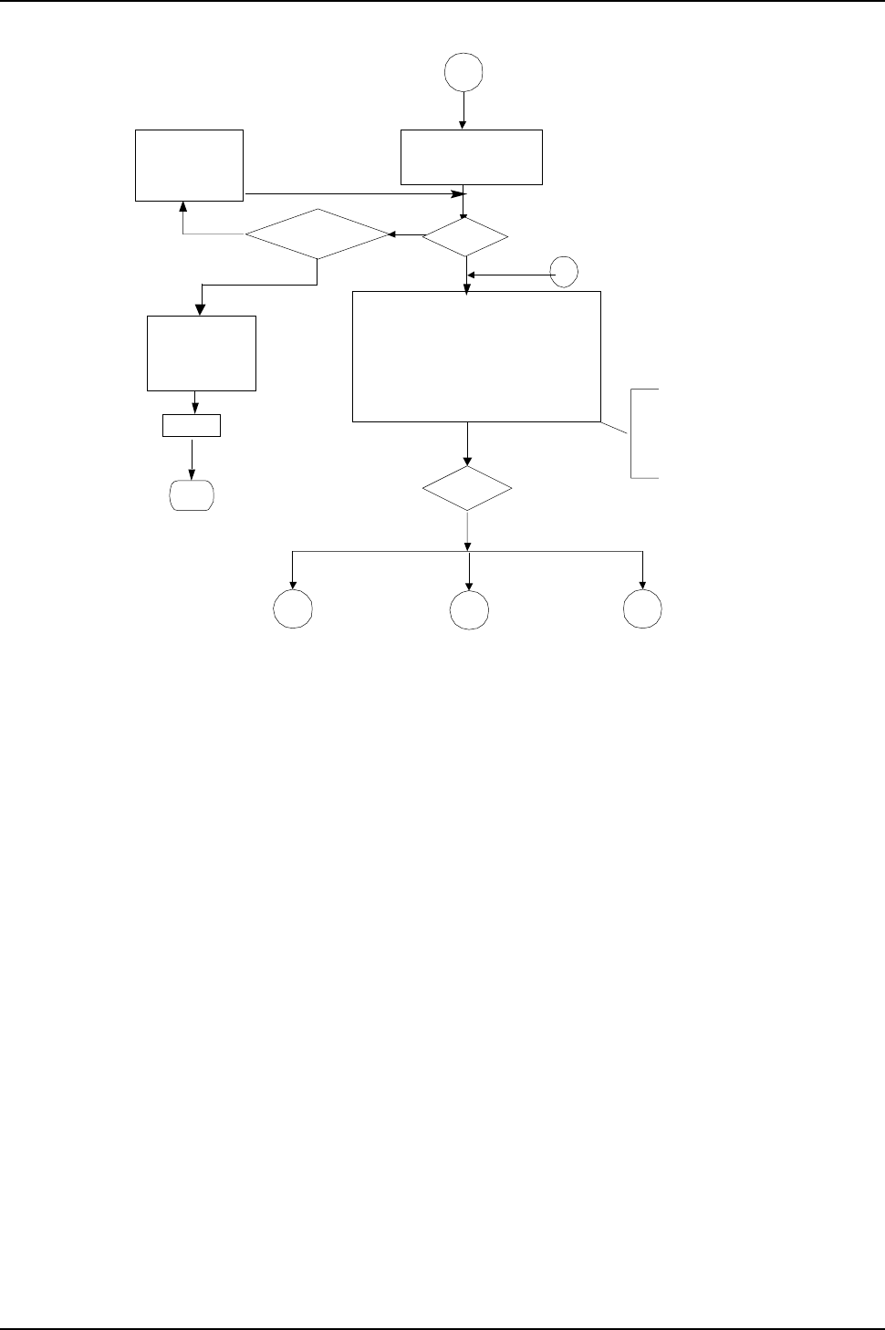
IG6600 Administration Manual
Page 131 of 139
Appendix 3.2.4 System Administrator’s Voicemail Flowchart
4
Yes Is password
correct?
Yes
Hang up
End
No
19011
Option 3 is for internal
use only.Hence, it will
not be playback to user
to avoid any change to
recording
User input
4A
No
#1,2
41 4A
Recording greeting for various languages
3
42
Recording process voice files
19001
Please input the
administrator password
10505
The password is
incorrect, please
try again
Error Times=3
10506
Thepasswordis
incorrect, please
check it and try
later
To record the first language
greeting, press one
To record the second language
greeting, press two
When finish, press the pound (#)
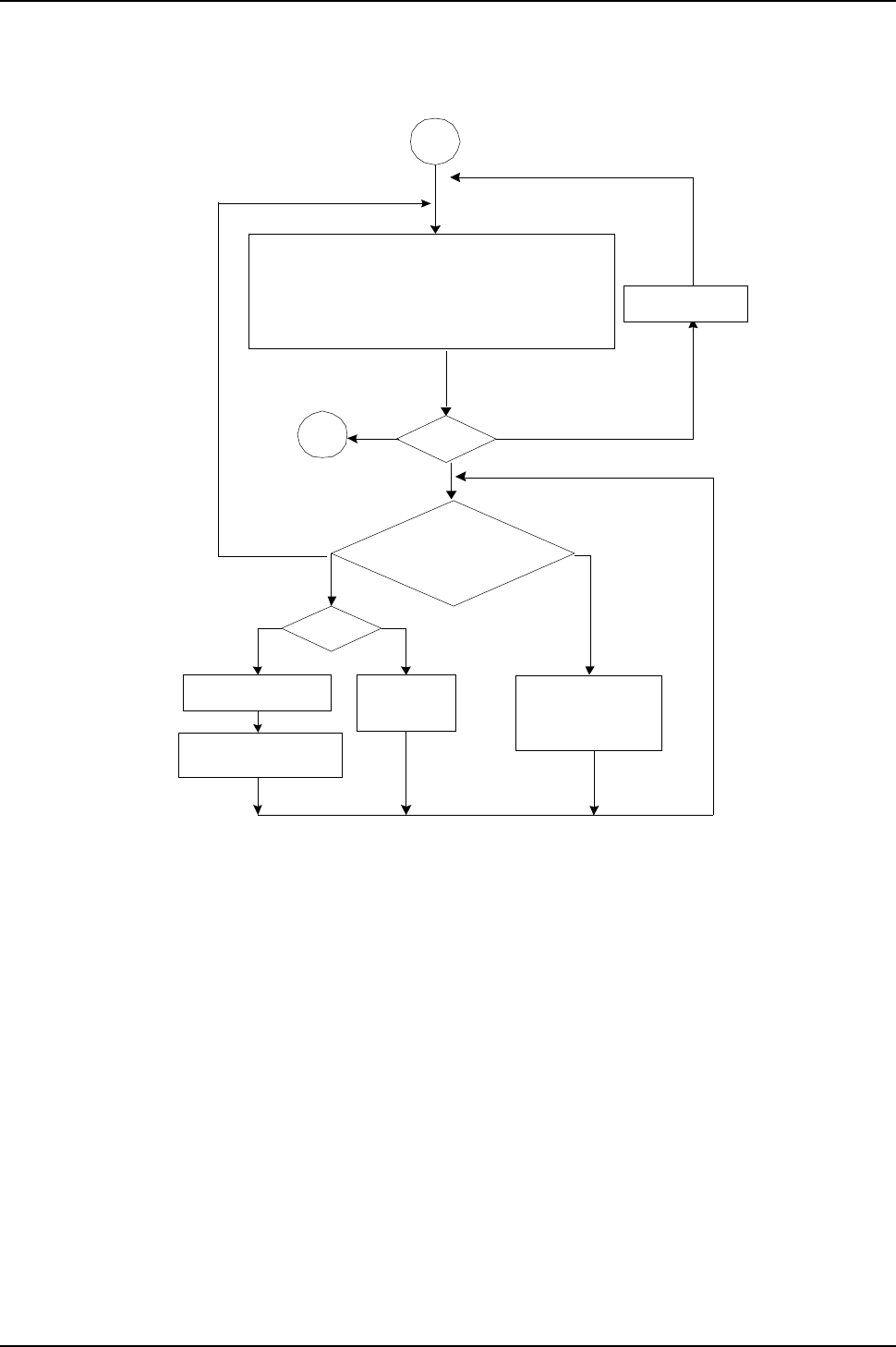
IG6600 Administration Manual
Page 132 of 139
Appendix 3.2.4.1 Recording Various Greeting
19012
others
41
User input4A
19013
Isthere
voice file?
10305
Yes No
10601
12
1,2,3,4
19015
#
#
Playback voice
file
Input incorrect
End of messages
There are no
recordings
Please begin to record
after the beep, when
finish, press the pound
To listen to current greeting press one
To record the greeting, press two
When finished, press the pound (#)
To record the greeting for regular office hours, press one
To record the greeting for out of office hours, press two
To record the greeting for lunch time break, press three
To record the greeting for holidays, press four
When finish, press the pound (#)
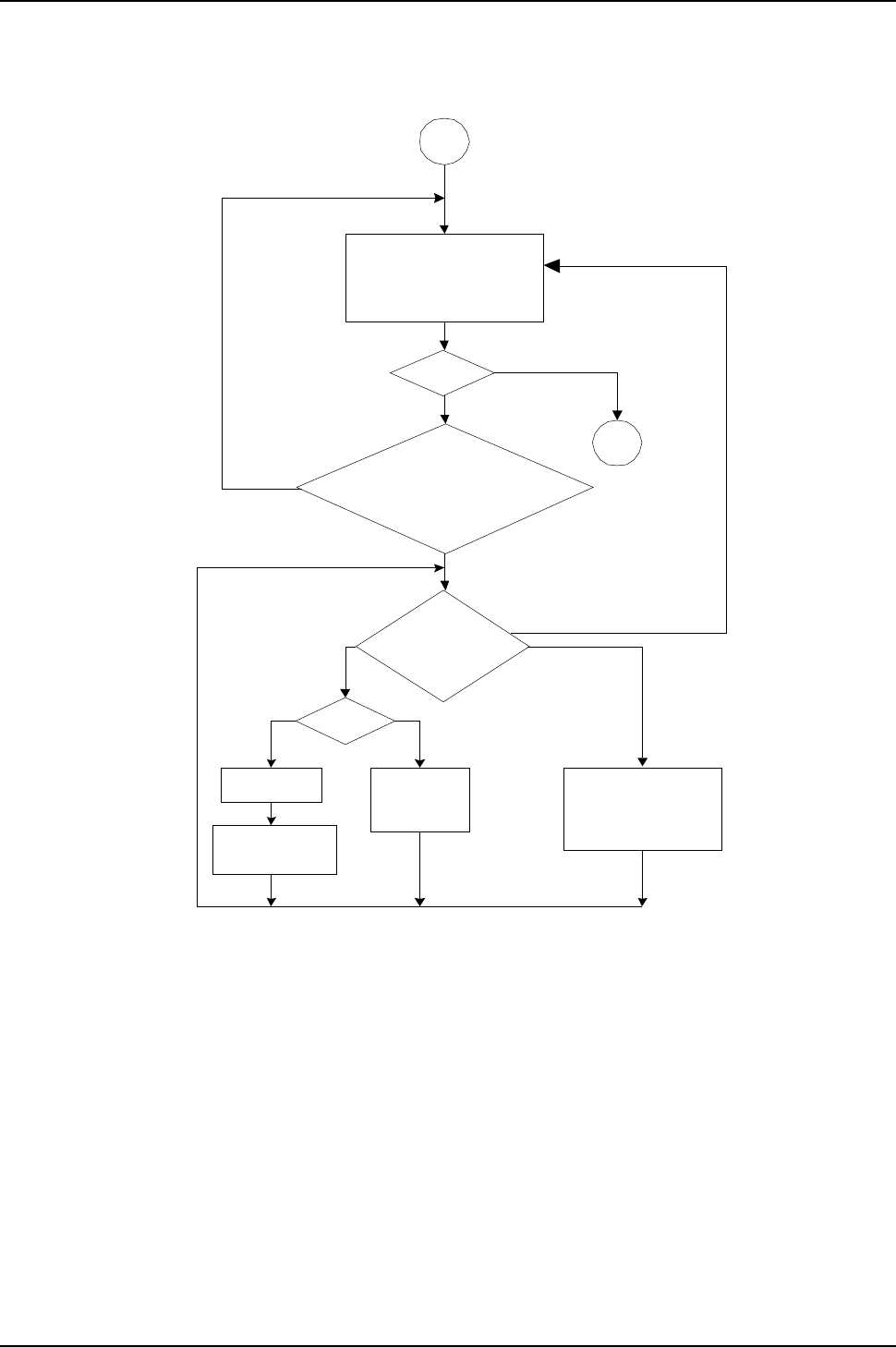
IG6600 Administration Manual
Page 133 of 139
Appendix 3.2.4.2 Recording Process Voice Files
42
19200
Is ‘#’?
4A
19013
Is there
voice file?
Playing
voice
fil
e
Yes No
12
10305
1
Yes
No
19201+10528
2or #
19015 10601
#
Please input five digits
number voice code.
To cancel the input, please
press the pound(#)
The voice code that you entered is xxxxx
To confirm the new input, press one.
To reenter, press two.
To cancel and return to the previous menu,
press the pound (#)
To listen to current
greeting press one
To record the greeting,
press two
When finished, press
the pound (#)
There are no
recordings
End of messages
Please begin to record
after the beep, when
finish, press the pound
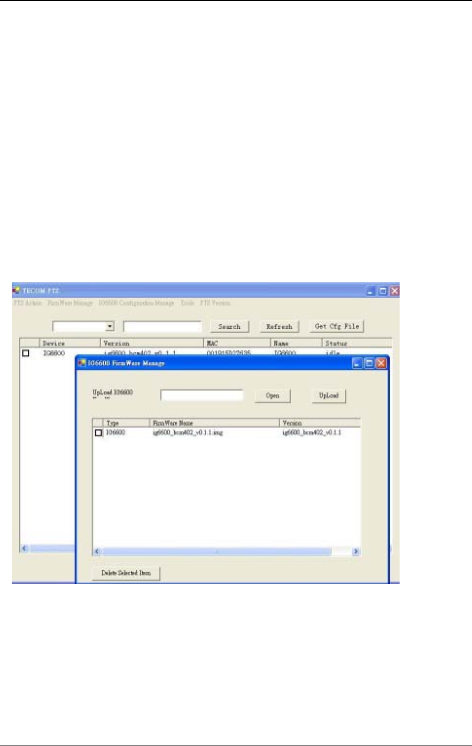
IG6600 Administration Manual
P
134
of
139
Appendix 4: PTS/PTC
PTS and PTC is the remoter Management for IG6600.
PTS is the centralized management server run in the MS windows OS.
PTC is the terminal client run on IG6600.
PTS/PTC can update IG6600 firmware, update IG6600 configure file, update IP2032,
IP2061 and IP2062 firmware.
Install PTS
Run the Setup.Exe in PTS Release folder. First it will install the MS .NET framework 1.1
first and then install the PTS application.
Update IG6600 Firmware
1. Press “FirmWare manage”-> “IG6600 FW manage”, then upload firmware.
2. Press refresh button to show registered device in main form.
3. Selected device and press “PTS action”-> “IG6600 FirmWare Update”.
4. In “IG6600 FirmWare Update”, choose the firmware and press update button.
5. The PTS will inform IG6600 to download firmware when IG6600 register again.
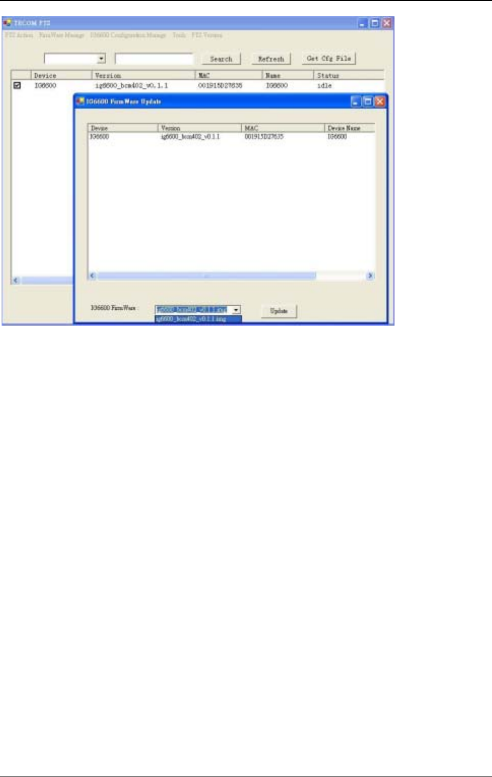
IG6600 Administration Manual
P
135
of
139
Update IG6600 Configuration File
1. Press refresh button to show registered device in main form.
2. Selected device and press “PTS action”-> “IG6600 Configure File Update”
3. In “IG6600 Configure File Update”, choose the configure file and press update button.
4. The PTS will inform IG6600 to download configure file when IG6600 register again.
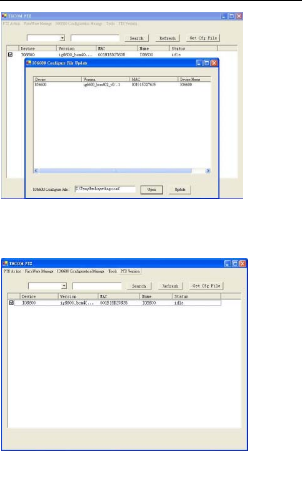
IG6600 Administration Manual
P
136
of
139
Receive IG6600 Configuration File
1. Select device at Main Form
2. Press “Get Cfg File”button.
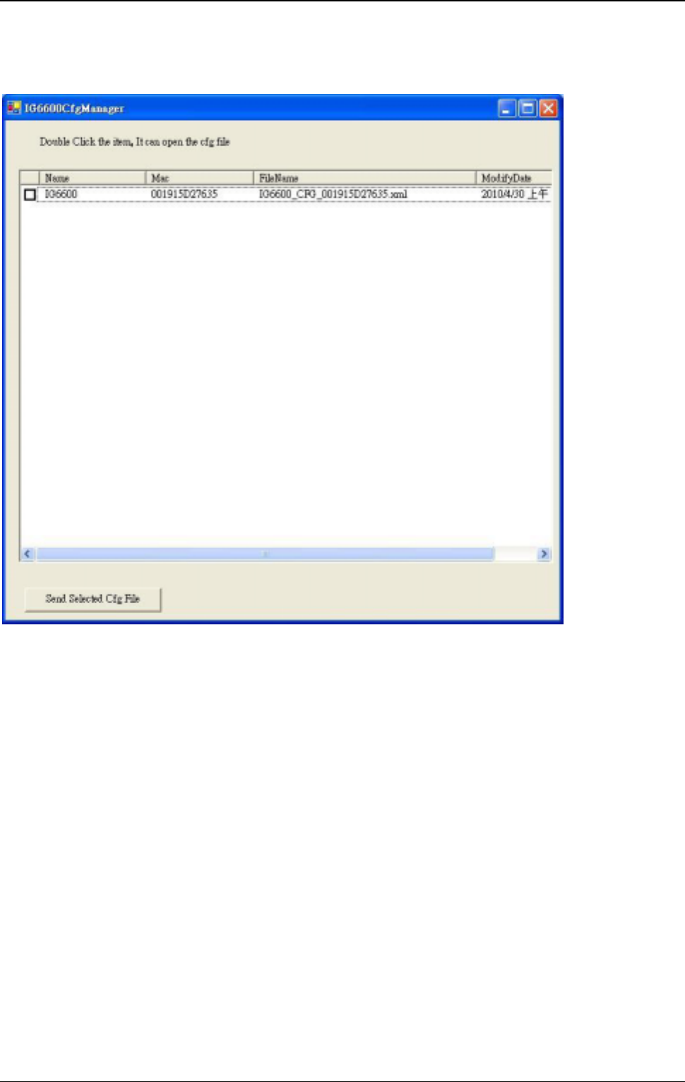
IG6600 Administration Manual
P
137
of
139
3. The status will change from idle to waiting and then loading. After status back to idle ,
press “IG6600 Configuration Manage”at the top menu
4. Double click the item, it will open the configure file as xml format. And you can edit the
configure file (the tool which open the cfg file is the default xml edit tool on your PC)
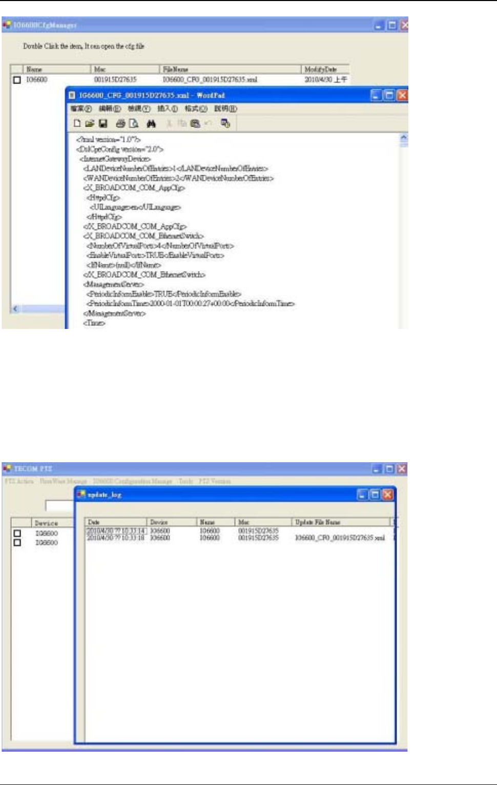
IG6600 Administration Manual
P
138
of
139
5. After editing file, the configuration file can send back to IG6600 by pressing “Send
Selected Cfg File”button
Show Update Log
Press”To ol s ”-> “log”, it will show the log of update
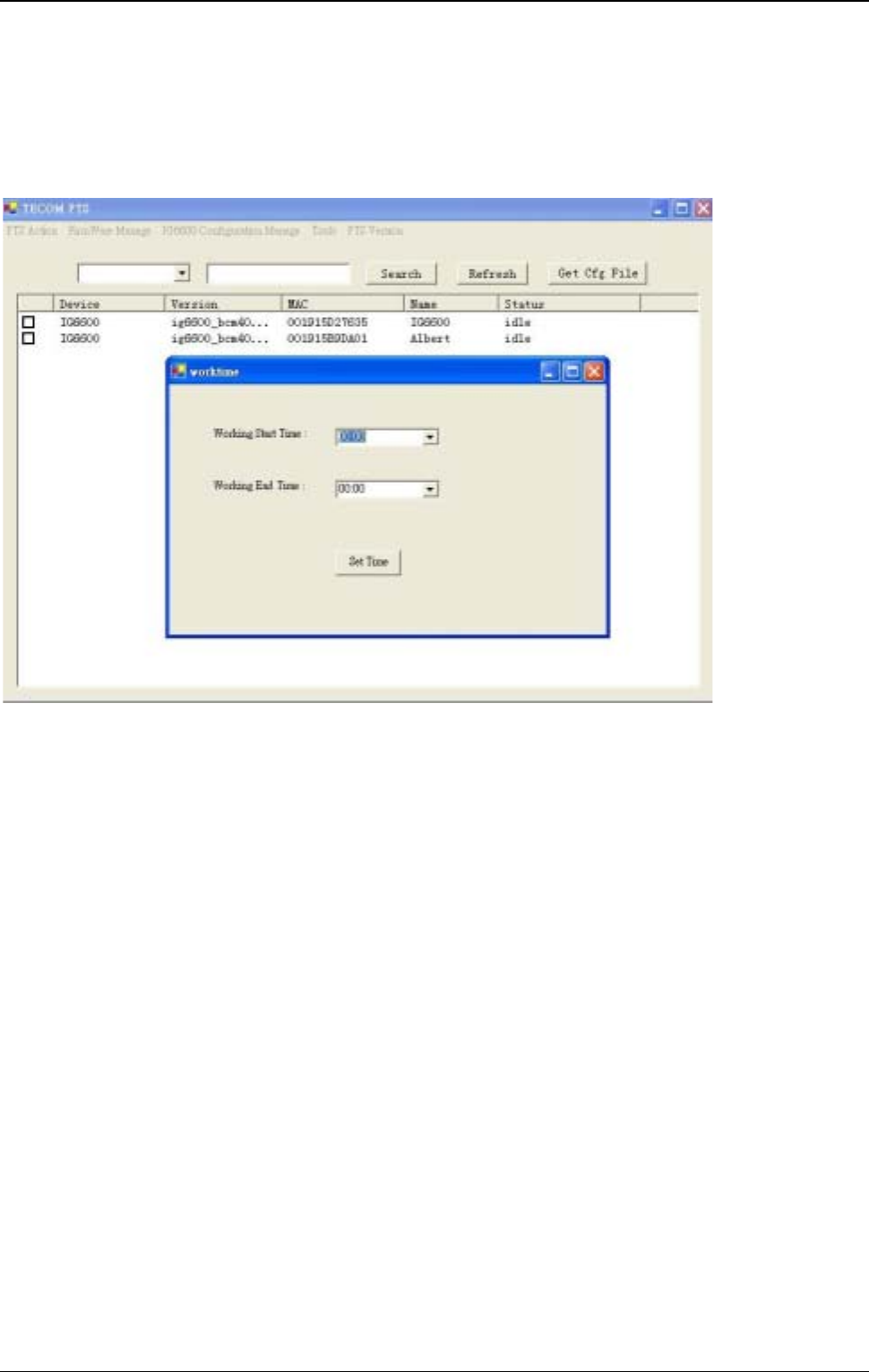
IG6600 Administration Manual
P
139
of
139
Set Working Time
Working Time configure is for update IG6600, IP Phone pending task.
Press “Tools”-> “Working Time”.