Tekk BCH-220 Scanning Receiver User Manual Scanning receiver English Manual
Tekk International Inc. Scanning Receiver Scanning receiver English Manual
UserManual.wiki
>
Tekk
>
BCH 220 User Manual
User Manual
Navigation menu
Upload a User Manual
Namespaces
Wiki Guide
HTML
PDF
Info
Views
User Manual
Discussion / Help
Navigation
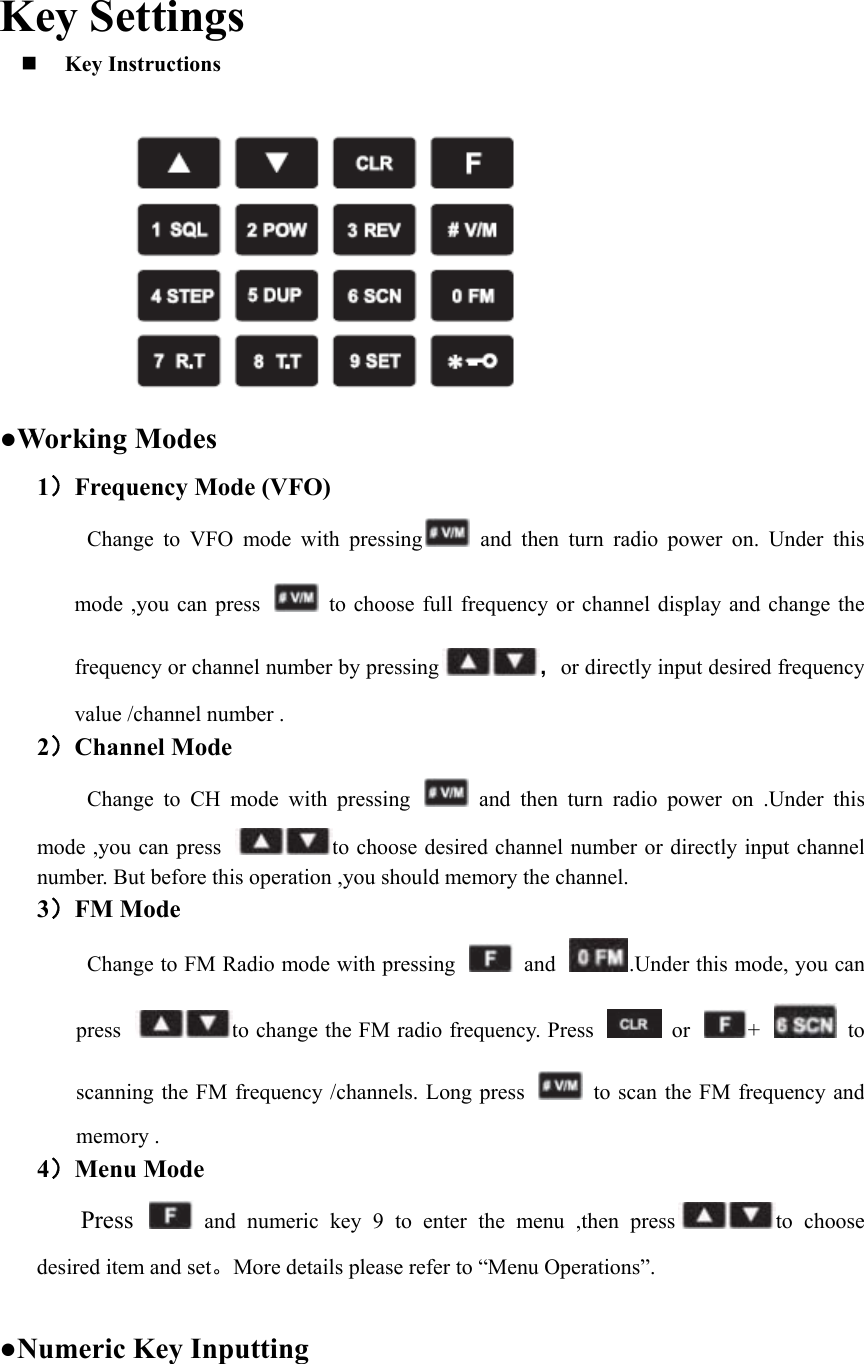
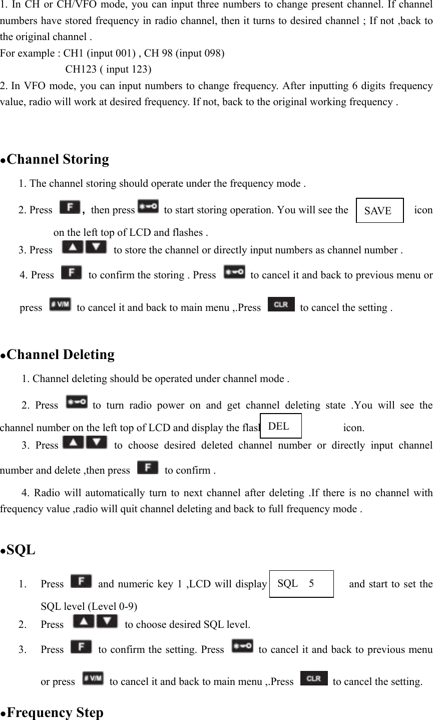
![5 Directly input numeric key 0-9 to get desired CTCSS/DCS. See followings : Input 102.5Hz for CTCSS. a) Press to exchange CTCSS and DCS. b) Input numbers : 1,0,2,5。 c) Same operation for DCS input. 6 Press to confirm the setting. Press to cancel it and back to previous menu or press to cancel it and back to main menu ,.Press to cancel the setting.(Note :You cannot set the RX signaling when radio in channel mode .) Side-Keys Programming Function See following side-key functions: English Details OFF No function available SCAN Scanning frequency/memorial channel ,press any key except [▲] / [▼] to quit scanning . VOX Turn on/off VOX MONITOR Stop/Start monitor the CTCSS or DCS ,meanwhile radio automatically turn on SQL when receives carrier signal. FM RADIO Turn on/off FM radio FIR CH exchange to the first channel SEC CH exchange to quick channel SQL OFF Turn on SQL and while receive carrier signal ,radio speaker actives. SQL MOM Active this SQ , and keep at SQ state when radio receives carrier wave (Short press is invalid for this function) Operation Instructions BEEPER ON/OFF Press and ,choose BEEPER by and LCD displays ,then press and to choose ①ON ;②OFF. After that ,press to confirm and back to selected item . Press to cancel setting and back to previous item or press to cancel setting and back to main menu. BEEP](https://usermanual.wiki/Tekk/BCH-220/User-Guide-2804612-Page-15.png)