Tekk BCH-220 Scanning Receiver User Manual Scanning receiver English Manual
Tekk International Inc. Scanning Receiver Scanning receiver English Manual
Tekk >
User Manual

Content
Brief Introduction
Thank you for buying scanning receiver. The goal is to provide cost-effective communication
equipment for a variety of business sites and the amateur and supply all fast-paced walks of life
with perfect communication solutions.
This product uses amateur frequency ,you need to apply for use to radio management
institution of the provinces, cities or autonomous regions .
please read this manual carefully in order to know how to properly operate the radio before
use.
Unpacking and Checking Equipment
Welcome to use radios, before using we suggest you:
·Please check the packing box of this product and see if there are signs of damage.
·Please open the packing box carefully. We recommend that you identify the items listed in the
following packing list. if you find that our product and its accessories in handling are lost or
damaged during the shipment. Please immediately contact dealers.
Parts List
Item Quantity
Rubber Antenna 1
Li-ion Battery Pack 1
Desktop Charger 1
Power Adapter 1
Belt Clip 1
User’s Manual 1
Warranty Card 1
Hand Strap 1
Preparation
Charging the Battery
1. Using the battery
The battery is not completely charged at the factory, please charge it before using.
To extend the battery life time, please power off the battery when you don't use two way
radio, and save battery in a cool (temperature less than 25 )and dry place.℃
2 Precautions of Charging Equipment
1. Do not expose the charger to rain or snow.
2. Do not operate the charger if it has received a sharp blow, or has been dropped or damaged
in any way.
3. Do not disassemble the charger if it has received a sharp blow, or has been dropped or
damaged in any way.
4. Never alter the AC cord or plug provided with the unit. If the plug will not fit the outlet,
have the proper outlet installed by a qualified electrician. An improper condition can result
in a risk of electric shock.
5. To reduce the risk of damage to the cord or plug, pull the plug rather than the cord when
disconnecting the charger from the AC receptacle.
6. To reduce the risk of electric shock, unplug the charger from the outlet before attempting
any maintenance or cleaning.
7. Use of an attachment not recommended or sold by JUSTON may result in a risk of fire,
electric shock, or personal injury.
8. Make sure the cord is located so it will not be stepped on, tripped over, or subjected to
damage or stress.
9. An extension cord should not be used unless absolutely necessary. Use of an improper
extension cord could result in a risk of fire and/or electric shock. If an extension cord must
be used, make sure that:
•The pins on the plug of the extension cord are the same number, size, and shape as those
on the plug of the charger.
•The extension cord is properly wired and in good electrical condition.
•The cord size is 18 AWG for lengths up to 100 feet, and 16 AWG for lengths up to
150feet.
10. Do not replace charger's power cord. If the power cord damages, you must stop using
charger immediately.
3. Charging the Battery
Please use the battery charger designated by to charge battery. After purchase or extended
storage (more than two months), the first time to charge battery cannot make battery reach
its normal operating capacity. After repeating charge /discharge it two or three times, the
operating capacity will increase to its normal capacity.

4. Please Charge the Radio According to Operation Steps as Follows:
1. Insert power adapter into power supply socket.
2. Insert output terminal of power adapter into DC jack behind the charging kit, now the
charging orange indicator lights about 2 seconds then goes out.
3. Insert the battery or radio equipped with battery into the charging kit.
4. Confirm the battery and charging kit terminal contact reliably, when charging indicator
light turns into red and charging starts.
5. After completion of charge (charging time about 5 hours), light turns to be green.
5. Indicators Display As Following:
Status Indicator
Power Connected Orange light is on about 2 seconds then goes out
No battery(temperature end judges) All go out
Charge normally Red light is on
The battery is fully charged Green light is on
Fault (over temperature, battery short
circuit or over discharge state)
Red light flashes
Note: Before charging, please turn off radio power equipped with battery. When
charging, using radio will interfere with normal charge of battery and receiver effect.
Basic operations
Power On/Off
Turn the power switch knob clockwise to turn on radio power; to turn it off ,turn
the power switch knob counter-clockwise.
Volume Control
Turn the volume switch knob clockwise to increase volume; to decrease the
volume, rotate the volume switch knob counter-clockwise.
RX
When radio receiving information ,green LED lights .
1) Only same signaling and CTCSS setting can receive information .
2) May not receive any calling if radio is at lower signal and set high level SQL.
3) Local dealer maybe program your radio with CTCSS/DCS . Users can receive the same
signaling information if chosen channel with CTCSS/DCS . Or it can not get any calling .
R
a
s
p
p
r
L
1
2
3
4
5
6
7
8
9
1
0
1
1
1
2
a
dio with CT
p
ecial channe
l
r
ogrammed t
h
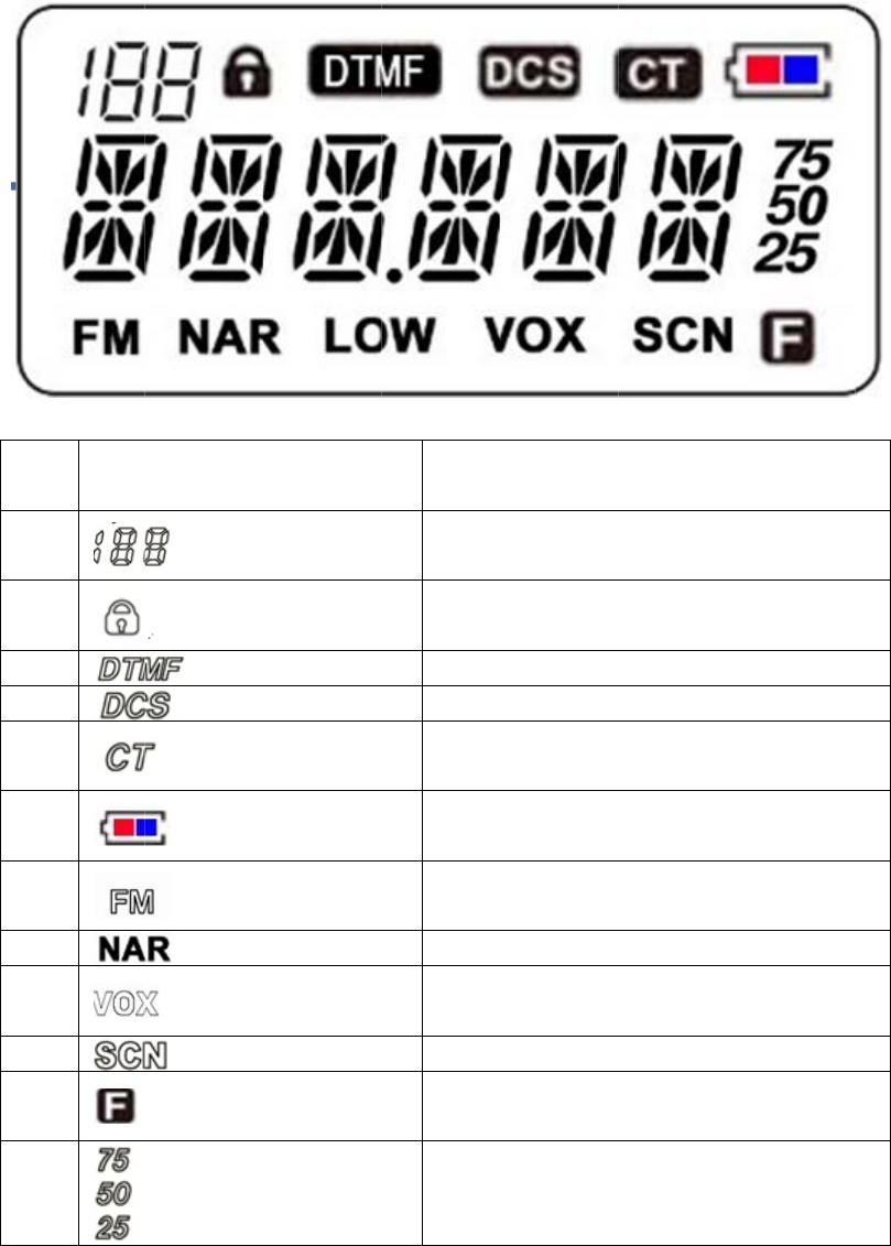
L
CD Ic
o
0
1
2
CSS/DCS w
i
l
for CTCSS
/
h
e same CTC
o
ns Ins
t
Ico
n
i
ll help you t
o
/
DCS ,radio
a
SS /DCS .
t
ructio
n
n
s
o
ignore inef
f
a
lso can com
m
n
f
ective callin
g
m
unicate wit
h
Ins
t
Ch
a
K
F
N
a
F
Last Di
g
g
. Although
t
h
other radio
t
ructions
a
nnel/Menu
K
ey Lock
DTMF
DCS
CTCSS
Battery
F
M Radio
a
rrow Band
VOX
Scan
F
unction
g
its at Freque
n
t
here seems
which
n
cy
Program Settings
Radio Basic Information
1) Frequency
Please type in desired frequency value.
2) Back to factory default settings
You can initialize factory default settings by program software.
3) Delete Channel Group
You can delete the chosen channel by program software .
4) Turn On SP
Turn on speaker, you can hear sound from radio when it receives correct signaling.
Optional Items
1)Alarm before TOT
You can set an alert tone sounds from the speaker before TOT is cut.
2)Voice Report
Your radio can choose different languages voice report : English ,Chinese ,Off .
1) Beeper of Radio Power On
Choose desired beeper to sound when turn on the radio .
2) SQL
The purpose of the squelch is to mute the speaker when no signals are present. With the squelch
level ( 0-9) correctly set , you will hear sound only while actually receiving signal. The higher
the selected squelch level, the stronger the signals must be when receive. The appropriate
squelch level depends on ambient RF noise conditions.
3) Key Lock
1.Long press this key with lock icon .
2.Auto-lock: Set time to active auto-lock .It will be invalid when turn on radio again .
3.Auto-lock + memory : Set time to active auto-lock .It will be valid when turn on radio
again.
4) Working Mode
Frequency: LCD display frequency value.
Channel: LCD display channel No.
Frequency +Channel: LCD display both modes .
5)Frequency Step
There are 2.5K ,6.25K .........100K for selectable.
7)Back Light
Choose to turn on/off backlight and set lighting duration.
9)Channel Name Display
Only available at channel mode .
Tick √: Display
Not tick √: No Display
10)Beeper
Turn beeper on/off . If turn off beeper ,key tone and power on tone will not be available .
11)Decode Tail Elimination by Frequency Without CTCSS/DCS Decode
Tail tone elimination by frequency at channel without CTCSS/DCS decode .
12)Encode Tail Elimination by Frequency Without CTCSS/DCS Encode
Tail tone elimination by frequency at channel without CTCSS/DCS encode .
13)Key Lock
Enable the key lock function.
14)UP/DOWN Lock
Enable UP/DOWN lock function.
15)Support Non-standard CTCSS and DCS
Your radio can set any desired non-standard CTCSS and DCS
Scan
Scan Mode
According to chosen scan mode ,radio stops or continues to scan.
1)Time Mode: Your radio stops scanning when detecting a signal for some while(approximately
5 seconds).and then continues to scan even if the signal is still present.
2)Carrier Mode: Your radio stops scanning when detecting a signal and remains on the same
channel until the signal drops out.
3)Search Mode : Radio stops at the scanned frequency or channel when detecting a signal.
Delay Time Between RX and Scanning
You can set the time of radio automatically back to scanning after RX .
Scanning Beeper On/Off
Your radio can turn on/off scanning beeper.
Scan Indicator
Turn on green light flashes when scanning.
Battery
Battery Save
The battery saver function decreases the amount of power used when a signal is not being
received and no operations are being performed ( no keys are being and no switches are being
turned ). But when your radio receives information first time ,the delay time will be longer .
Low Battery Beeper Type
You can choose the desired beeper for low battery alert.
Low Battery Alert Interval
Set the interval by every low battery alert .
APO
Radio will automatically turn off power if there is no operation within 5 minutes and alarm at
interval time before APO .Under APO mode, user can active radio by operating it again.
Off : Turn off APO function
APO Time : Turn on this function and set the time to auto power off as requested .
Low Battery Voice Report
Radio will report low battery state if active this function
APO at High Voltage
Radio automatically power off if the voltage higher than pre-set voltage value.
APO at Low Voltage
Radio automatically power off if the voltage lower than pre-set voltage value.
Emergency Call
1) Emergency Call Type
Local Emergency : Alert from radio .
Local Emergency + Remote Emergency: Alert from radio ,same as other radios with the same
frequency and same signaling .
2) Local Emergency Time
Continuous : Keep alerting
Limited time setting :Choose the desired time
3) Remote Emergency RX Time
Continuous : Keep alerting
Limited time setting :Choose the desired time
4) Emergency Call Circle Time
Choose desired circle time to make emergency call.
5) Channel Select
Assigned Channel : Suppose assigned at Channel 3 ,no matter what the present channel is ,alarm
always goes from Channel 3.
Present Channel: Suppose present channel is No.5 ,alarm from Channel 5.
Present channel is No.6 ,alarm goes from Channel 6.
6) Emergency Channel No.
Choose desired channel number from Group A and Group B as emergency channel.
First/Quick Channel
◆First Channel
Choose desired channel as first channel
◆Quick Channel
Choose desired channel as quick channel
Power On Settings
1) Display Information
Off: Display all functions’ icon.
Voltage :only display voltage value
Display Information :edited by user
2) Power On Message
Please edit the desired information by program for Group A and Group B.
3) Password to Power on
Radio default is to be no password .Users can freely set.
4) Password to Reset All Settings
Enable this function ,radio will back to pre-set state .
FM Radio
1) Monitor at FM Radio
Tick: RX available during FM radio working
No tick: No RX available during FM radio working
Note: Radio can monitor group A and group B at same time while listening to FM radio .
2) Working Mode
Full Frequency :makes FM radio work in Full frequency .
Channel: makes FM radio work in memorial channel .
3)FM SQL
Choose desired SQ level :1-32
4)FM VOL
Adjust desired FM Volume
5) FM Present Channel
Set the default channel when turn on FM radio
Input Information
This function allow radio input and store at most 16 letters or numbers , Chinese words. It also can
be used to store SN-code, identification for Program ID ,ID and so on .
DTMF Settings
Encode DTMF
■ Pre-carrier Frequency Duration : Set sending pre-carrier frequency duration before
sending DTMF ,so that you can get more accurate and stable information .Choose desired duration
from 0-5100 ms.
■ DTMF Code Interval : Set interval between ending sent DTMF and next DTMF , Choose
desired interval from 80-2450 ms.
■ Side Tone
This tone is for checking if the DTMF code sent by using radio.
■ DTMF Key Lock
You can lock the desired DTMF key

Decode DTMF
■ ID Code
The ID code is consisted of 1-10 digits .Radio decodes right DTMF when receiving matched radio
with programmed DTMF signaling .
■ Auto Reset Timer
If there is no communication after decoding DTMF code, DTMF code will be reset and make the
speaker quiet .Timer starts counting from stopping receiving carrier signal.
■ ID Group Calling
Define a universal group code by DTMF character A,B,C,D, *、#.
Radio can decode if receiving right ID code and one or all code will replaced by this universal
code .
For example :
Group C
Station 1 Station 2 Station 3 Station 4
Code 123 223 235 355
Calling C23 Station 1 and 2 called
Calling CC5 Station 3 and 4 called
Calling CCC All Station Called
■ Calling Alert
Indicator alert when receiving matched signaling.
■ Calling Alert Beeper
Beeper alter when receiving matched signaling.
■ ANI
Active this function to display the sender’s ID .
You can choose desired function :turn on/turn off.
■ Contact List
Edit and name sender’s ID on the log by programming software.
You can choose desired function :turn on/turn off.
Stun/Kill
1) Kill Code
Kill radio when it receives assigned code .Decode unless receive kill decode Stun+#.
2) Kill Group Code
Similar as ID Group Code .
For example :

Group C
Station 1 Station 2 Station 3 Station 4
Code 123 223 235 355
Base sending Kill Code C23 Station 1 and 2 killed.
Base sending Kill Code CC5 Station 3 and 4 killed
Base sending Kill Code CCC All Station killed
Note: Whatever radio power on again or not ,radio still memory the stun/kill function.
Automatically Dial List
Set DTMF code for every auto dial list .
Phone Book
Before dialing ,user input DTMF code which matched with desired person ,then quick to find out
desired person’s number.
Two Tone
Two Tone List
Set value for every two tone group.
Pre-carrier Frequency Duration
Set sending pre-carrier frequency duration before two tone code sending ,so that users can get
more accurate and
stable information .
Adjusting Volume for Two Tone ,End Tone and DTMF
You can choose desired volume level for two tone ,end tone and DTMF.
Auto Reset Timer
If there is no communication after decoding two tone code, The two tone code will be reset and
make the speaker quiet .Timer starts counting from stopping receiving carrier signal.
.
Side Tone
Enable radio reports when sending two tone.
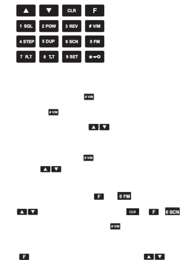
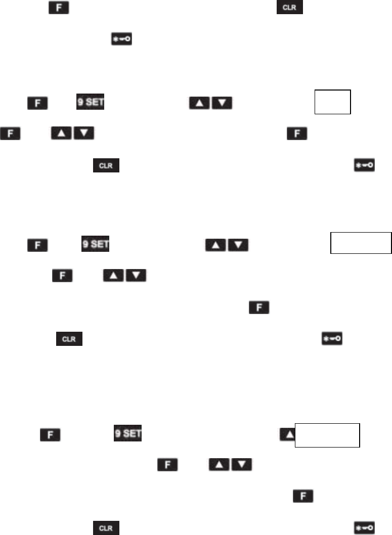
Key Settings
Key Instructions
●Working Modes
1)Frequency Mode (VFO)
Change to VFO mode with pressing and then turn radio power on. Under this
mode ,you can press to choose full frequency or channel display and change the
frequency or channel number by pressing ,or directly input desired frequency
value /channel number .
2)Channel Mode
Change to CH mode with pressing and then turn radio power on .Under this
mode ,you can press to choose desired channel number or directly input channel
number. But before this operation ,you should memory the channel.
3)FM Mode
Change to FM Radio mode with pressing and .Under this mode, you can
press to change the FM radio frequency. Press or + to
scanning the FM frequency /channels. Long press to scan the FM frequency and
memory .
4)Menu Mode
Press and numeric key 9 to enter the menu ,then press to choose
desired item and set。More details please refer to “Menu Operations”.
●Numeric Key Inputting
1. In CH or CH/VFO mode, you can input three numbers to change present channel. If channel
numbers have stored frequency in radio channel, then it turns to desired channel ; If not ,back to
the original channel .
For example : CH1 (input 001) , CH 98 (input 098)
CH123 ( input 123)
2. In VFO mode, you can input numbers to change frequency. After inputting 6 digits frequency
value, radio will work at desired frequency. If not, back to the original working frequency .
●Channel Storing
1. The channel storing should operate under the frequency mode .
2. Press ,then press to start storing operation. You will see the icon
on the left top of LCD and flashes .
3. Press to store the channel or directly input numbers as channel number .
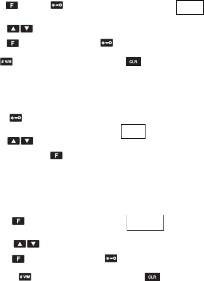
4. Press to confirm the storing . Press to cancel it and back to previous menu or
press to cancel it and back to main menu ,.Press to cancel the setting .
●Channel Deleting
1. Channel deleting should be operated under channel mode .
2. Press to turn radio power on and get channel deleting state .You will see the
channel number on the left top of LCD and display the flashing icon.
3. Press to choose desired deleted channel number or directly input channel
number and delete ,then press to confirm .
4. Radio will automatically turn to next channel after deleting .If there is no channel with
frequency value ,radio will quit channel deleting and back to full frequency mode .
●SQL
1. Press and numeric key 1 ,LCD will display and start to set the
SQL level (Level 0-9)
2. Press to choose desired SQL level.
3. Press to confirm the setting. Press to cancel it and back to previous menu
or press to cancel it and back to main menu ,.Press to cancel the setting.
●Frequency Step
SQL 5
SAVE
DEL
1. Press and numeric 4 ,LCD will display and start to set the
frequency step :2.5K、5K、6.25K、10K、12.5K、15K、20K、25K、30K、50K、
100K.
2. Press to choose desired step.
3. Press to confirm the setting. Press to cancel it and back to previous menu or
press to cancel it and back to main menu ,.Press to cancel the setting.
(Available in frequency mode )
●Frequency Reverse On/Off
Press and numeric 3 to exchange the frequency reverse function .You cannot
operate reverse frequency if there is no frequency on the channel .
●Offset Setting
Press and numeric key 5 to get the offset direction setting .(Available for frequency mode)
●Scanning
1 Press and numeric key 6 to start scanning .
2 Press to change scanning direction during scanning .
3 Under VFO mode ,radio will scan all the band at present frequency step
4 Under Channel mode ,radio will scan all 199 channels which program with frequency value .
5 Under FM mode , radio will scan all the frequency /channel.
Scanning will not be active if radio has less than 2 channels with frequency value and no more
adding channels.
●RX CTCSS/DCS
1 Press and numeric key 7 ,LCD will display and start to CTCSS/DCS
setting .
2 Press to exchange CTCSS and DCS. See followings:
OFF → CTCSS → DCS N → OFF
3 Press to exchange DCS direction. See followings:
DCS N → DCS I
4 Press to choose desired CTCSS/DCS.
67.0
6.25
K
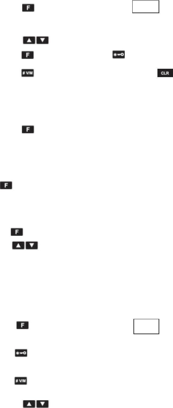
5 Directly input numeric key 0-9 to get desired CTCSS/DCS. See followings :
Input 102.5Hz for CTCSS.
a) Press to exchange CTCSS and DCS.
b) Input numbers : 1,0,2,5。
c) Same operation for DCS input.
6 Press to confirm the setting. Press to cancel it and back to previous menu or
press to cancel it and back to main menu ,.Press to cancel the setting.
(Note :You cannot set the RX signaling when radio in channel mode .)
Side-Keys Programming Function
See following side-key functions:
English Details
OFF No function available
SCAN Scanning frequency/memorial channel ,press any key except [▲] / [▼]
to quit scanning .
VOX Turn on/off VOX
MONITOR Stop/Start monitor the CTCSS or DCS ,meanwhile radio automatically
turn on SQL when receives carrier signal.
FM RADIO Turn on/off FM radio
FIR CH exchange to the first channel
SEC CH exchange to quick channel
SQL OFF Turn on SQL and while receive carrier signal ,radio speaker actives.
SQL MOM Active this SQ , and keep at SQ state when radio receives carrier wave
(Short press is invalid for this function)
Operation Instructions
BEEPER ON/OFF
Press and ,choose BEEPER by and LCD displays ,then
press and to choose ①ON ;②OFF. After that ,press to confirm and
back to selected item . Press to cancel setting and back to previous item or press to
cancel setting and back to main menu.
BEEP
BACK LIGHT
Press and and choose LIGHT by and LCD displays
Then press and to choose ①ON; ②OFF. ③Choose desired timing to keep
lighting. After that ,press to confirm and back to selected item . Press to cancel
setting and back to previous item or press to cancel setting and back to main menu.
KEY LOCK
Press and ,choose LOC.KEY by and LCD displays .
Then press and to choose ①MANU: Lock the key by manual ;②AT 5/.../30:
Lock the key within defined timing and radio do not memory the auto key lock status if turn on
again.; ③AS 5/…/30:Lock the key within defined timing and radio memory the auto key lock
status if turn on again. After that ,press to confirm and back to selected item . Press
to cancel setting and back to previous item or press to cancel setting and back to
main menu.
BATTERY SAVE
Press and ,choose SAVE by and LCD displays .Then
press and to choose ①OFF; ②1-1/1-2/.../1-10: Ratio for battery saving (1-1
highest battery consumption, 1-10 lowest battery consumption )After that ,press to confirm
and back to selected item . Press to cancel setting and back to previous item or press
to cancel setting and back to main menu.
VOX SWITCH
Press and ,choose VOX SWI by and LCD displays
Then press and to choose ①OFF; ②ON. After that ,press to confirm
and back to selected item . Press to cancel setting and back to previous item or press
to cancel setting and back to main menu.
VOX.SWI
SAVE
L
OC.
KEY
LIGHT
VOX
Press and ,choose VOX LEV by and LCD displays
Then press and to choose desired VOX level . After that ,press to
confirm and back to selected item . Press to cancel setting and back to previous item or
press to cancel setting and back to main menu.
POWER ON MESSAGE
Press and ,choose PON MSG by and LCD displays
.Then press and to choose ①OFF: Display all icons .②DC: Display only
voltage ;③MSG:Display only message .After that ,press to confirm and back to
selected item . Press to cancel setting and back to previous item or press to cancel
setting and back to main menu.
APO
Press and ,choose APO by and LCD displays .Then press
and to choose ①OFF; ②1H…24H: Timing for automatically power off . After
that ,press to confirm and back to selected item . Press to cancel setting and back
to previous item or press to cancel setting and back to main menu.
ROGER
Press and ,choose ROGER by and LCD displays .
Then press and to choose ①OFF; ②ON. After that ,press to confirm
and back to selected item . Press to cancel setting and back to previous item or press
to cancel setting and back to main menu.
OFFSET
Press and ,choose OFF SET by and LCD displays
OFF.SET
ROGER
APO
PON.MSG
VOX.LEV
.Then press and to choose desired frequency difference
receiving . After that ,press to confirm and back to selected item . Press to
cancel setting and back to previous item or press to cancel setting and back to main menu.
WIDE/NARROW BAND
Press and ,choose W/N by and LCD displays .Then
press and to choose ①WIDE ②NARR. After that ,press to confirm
and back to selected item . Press to cancel setting and back to previous item or press
to cancel setting and back to main menu.
SCANNING
Press and ,choose SC MOD by ,LCD displays
.Then press and to choose ①SE: Searching ②CO:
Carrier wave ;③TO:Tim. After that ,press to confirm and back to selected item . Press
to cancel setting and back to previous item or press to cancel setting and back to
main menu.
SCANNING ADD/DEL
Press and , choose SC ADD by and LCD displays .Then
press and to choose ①ADD:;②DEL: delete. After that ,press to
confirm and back to selected item . Press to cancel setting and back to previous item or
press to cancel setting and back to main menu.
VOICE
Press and , choose VOICE by and LCD displays . Then
press and to choose ①CHS: Chinese; ②ENG: English ;③OFF. After
VOICE
SC.ADD
SC.MOD
W/N
that ,press to confirm and back to selected item . Press to cancel setting and back
to previous item or press to cancel setting and back to main menu.
ANI
Press and ,choose ANI by and LCD displays . Then press
and to choose ①ON ;②OFF. After that ,press to confirm and back to
selected item . Press to cancel setting and back to previous item or press to cancel
setting and back to main menu.
TOP KEY
Press and , choose Top Key by and LCD displays
Then press and to choose desired program function, more details can refer to
the above keys programming definition. After that ,press to confirm and back to selected
item . Press to cancel setting and back to previous item or press to cancel setting
and back to main menu.
RESET
Press and ,choose reset by ,LCD displays
,then press and to choose ①VFO: reset all settings
except memorial channels ②FULL:All settings. After that ,press to confirm and back to
selected item . Press to cancel setting and back to previous item or press to cancel
setting and back to main menu.
RESET
TOP.KEY
ANI
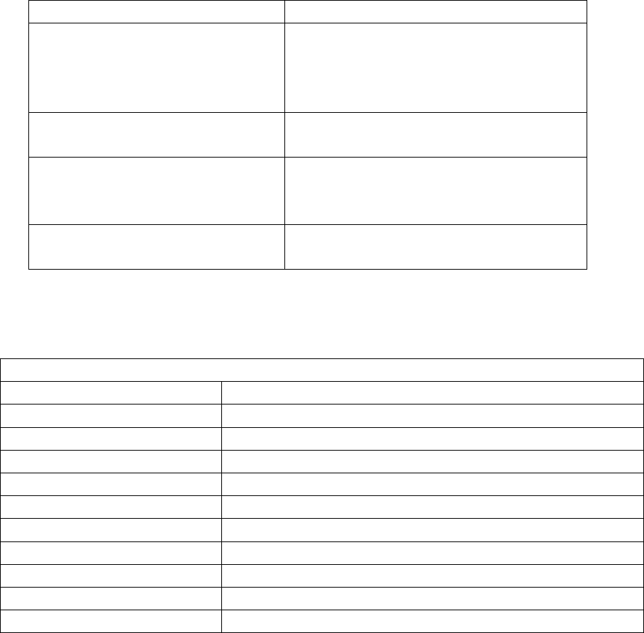
Troubleshooting
Symptom Try This
No power
Battery power may have run out, please
update battery or recharge it.
Battery may not be properly installed,
please take it off and re-install.
Battery lasts a short time after charge The battery life is over, please replace new
battery.
Can not talk to other members of your
group.
Verify channel, frequency and code
settings are correct.
Hearing other conversation on a
channel (not group members’)
Please change code settings, including all
two way radio settings of your group.
Specifications and Parameters
General Specification
Device Number(D/N) A31
Frequency Range 200-260 MHz
Channel 199 channels
Channel Spacing Narrowband:12.5KHz
CTCSS/DCS 50 CTCSS / 105 DCS
Antenna Impedance 50 Ohm
Working Temperature –20 to ℃+50℃
Working Voltage DC7.4v
Battery Type Li-ion battery
Dimension(antenna excluding) 110.5( H )×58.5( W ) ×35.6(D)mm
Weight (include antenna, battery) About 230 grams

Appendix I CTCSS (Hz)
1-67.0 14-103.5 27-159.8 40-199.5
2-69.3 15-107.5 28-162.2 41-203.5
3-71.9 16-110.9 29-165.5 42-206.5
4-74.4 17-114.8 30-167.9 43-210.7
5-77.0 18-118.8 31-171.3 44-218.1
6-79.7 19-123.0 32-173.8 45-225.7
7-82.5 20-127.3 33-177.3 46-229.1
8-85.4 21-131.8 34-179.9 47-233.6
9-88.5 22-136.5 35-183.5 48-241.8
10-91.5 23-141.3 36-186.2 49-250.3
11-94.8 24-146.2 37-189.9 50-254.1
12-97.4 25-151.4 38-192.8
13-100.0 26-156.7 39-196.6
Appendix II DCS
023 071 143 225 266 356 452 532 664
025 072 145 226 271 364 454 546 703
026 073 152 243 274 365 455 565 712
031 074 155 244 306 371 462 606 723
032 114 156 246 311 411 464 612 731
036 115 162 245 315 412 465 624 732
043 116 165 251 325 413 466 627 734
047 122 172 252 331 423 503 631 743
051 125 174 255 332 431 506 632 754
053 131 205 261 343 432 516 645
054 132 212 263 346 445 523 654
065 134 223 265 351 443 526 662
FCC Statement
This device complies with part 15 of the FCC Rules. Operation is subject to the following two
conditions: (1) This device may not cause harmful interference, and (2) this device must accept
any interference received, including interference that may cause undesired operation.
Any Changes or modifications not expressly approved by the party responsible for compliance
could void the user's authority to operate the equipment.
The scanner receiver equipment meets the requirements of the FCC Rules, 15.121 (a)
The scanner receiver in this equipment is incapable of tuning, or readily being altered, by the User
to operate within the frequency bands allocated to the Domestic Public Cellular
Telecommunications Service in Part 22. Blocking of the cellular frequencies is implemented in the
firmware of the unit’s main control central processing unit (CPU). Coverage of 824 - 849 MHz
and 869 - 894 MHz is completely blocked, since it is done in the microprocessor, and cannot be
re-enabled by any user-accessible procedure, including diode, resistor, or jumper changes, nor by
connection of any external device such as a personal computer, nor by installation of any “special”
enabling semiconductor device. The scanning receiver is designed so that the tuning, control and
filtering circuitry is inaccessible.