Teko Telecom Srl DFE Digital Front End User Manual
Teko Telecom Srl Digital Front End
Contents
- 1. Users Manual
- 2. User Manual
User Manual
www.tekotelecom.it
www.tekotelecom.it
Let us repeat !
SIRIUS: Teko Telecom Modular Coverage and Capacity System
TECHNICAL HANDBOOK
Doc ID Number 91 080 0781 - Rel. 04
english
www.tekotelecom.it
www.tekotelecom.it
Let us repeat !
english
Doc ID Number 91 080 0781 - Rel. 04
BOLOGNA, 11/10/2010
UPDATINGS:
Rel. 02 (11/04/2011)
Rel. 03 (15/03/2012)
Rel. 04 (11/06/2012)
Document Identication Number
91 080 0781 – Rel. 04
SIRIUS: Teko Telecom Modular Coverage and Capacity System

www.tekotelecom.it
www.tekotelecom.it
SIRIUS: Teko Telecom Modular Coverage and Capacity System
Let us repeat !
Doc ID Number 91 080 0781 - Rel. 04 page 3
english
Table of Contents
1. Teko Telecom Modular Coverage and Capacity System - General Description ............. 10
1.1 Components ..........................................................................................................................11
1.1.1 Modules providing the RF interface towards the signal source ...................................... 13
1.1.2 Equipment extending coverage / distributing capacity ..................................................... 20
1.1.3 Modules providing the optical interface towards Remote Units .................................... 23
1.1.4 Passive Modules providing distribution and ltering .........................................................30
1.1.5 Modules for the management of the System ......................................................................... 39
1.1.6 Power Supply Modules ................................................................................................................... 44
1.1.7 Subracks hosting the System modules ..................................................................................... 46
1.1.8 Forced-air cooling Subrack ............................................................................................................ 47
1.2 Coverage and Capacity Solutions ......................................................................................48
1.2.1 Modular O-air Repeaters - General description .................................................................. 48
1.2.2 Optical Systems - General Description ...................................................................................... 51
A – Master Unit ...........................................................................................................................................51
B – Remote Units .......................................................................................................................................57
1.2.3 Coverage Systems Management and Power Supply ........................................................... 65
1.2.4 Teko Telecom Coverage Systems Technical Specications ................................................ 69
2. System Installation ...................................................................................................................72
2.1 Mechanical Installation .......................................................................................................73
2.1.1 Positioning Master Unit Subracks ............................................................................................... 75
2.1.2 Positioning Remote Units .............................................................................................................. 76
2.2 Connections ...........................................................................................................................79
2.2.1 RF Connections .................................................................................................................................. 80
2.2.2 RS485 Connections ........................................................................................................................111
A – Connecting monitored subracks mounted within the same rack hosting the Master
subrack .......................................................................................................................................................112
B – Connecting remote monitored subracks ................................................................................113
2.2.3 Optical Connections ......................................................................................................................114
A – Connecting Master Unit to Remote Units ...............................................................................115

www.tekotelecom.it
www.tekotelecom.it
SIRIUS: Teko Telecom Modular Coverage and Capacity System
Let us repeat !
Doc ID Number 91 080 0781 - Rel. 04 page 4
english
B – Connecting Master point to point Modules to Slave point to point Modules ..........117
2.2.4 Power Supply and External Alarms connections .................................................................118
A – Active Subracks Power Supply Connection ...........................................................................119
B – Very High/High/Medium Power Remote Unit External Alarms Connection ..............122
C – Remote Units Power Supply Connection ................................................................................123
2.3 Power-Up ..............................................................................................................................126
3. System Commissioning ..........................................................................................................128
4. Preventive Maintenance ........................................................................................................130
4.1 Optical Fibres .......................................................................................................................130
4.2 Remote Units .......................................................................................................................130
4.2.1 Remote Units with passive cooling system (natural convection - fan unit not
equipped) ......................................................................................................................................................130
4.2.2 Remote Units with active cooling system (equipped with the fan unit) ....................130
5. Troubleshooting ......................................................................................................................133
5.1 Troubleshooting procedures ............................................................................................137
5.1.1 Active RF Interface Modules .......................................................................................................137
A – Digital Donor Front End module - MU-DFE ............................................................................137
B – Point of Interface module with remote controlled attenuators- TAPOI .......................141
5.1.2 Modules for the management of the System .......................................................................142
5.1.3 Power Supply Modules .................................................................................................................143
5.1.4 Modules providing the optical interface towards Remote Units ..................................144
A – Fiber Optic Transmitter/Receiver modules - MU-OTRX ......................................................144
B – Master and Slave Point to Point modules - MU-PTP ............................................................146
5.1.5 Equipment extending coverage/ distributing capacity ....................................................150
A – Service Front End Subrack ............................................................................................................150
B – Very High/High/Medium power Remote Unit .......................................................................151
C – SFE Subrack / Very High/High/Medium power Remote Unit ampliers ......................154
D – Very High/High/Medium power Remote Unit modules ...................................................156
E – Single/Dual/Triband Low power Remote Unit ......................................................................159
F – 5-band/6-band Low power Remote Unit ................................................................................163

www.tekotelecom.it
www.tekotelecom.it
SIRIUS: Teko Telecom Modular Coverage and Capacity System
Let us repeat !
Doc ID Number 91 080 0781 - Rel. 04 page 5
english
5.1.6 Forced-air cooling subrack ..........................................................................................................168
5.2 Flow charts ...........................................................................................................................169
5.2.1 Received Optical Power out of range - Uplink path ...........................................................170
5.2.2 Received Optical Power out of range - Downlink path .....................................................171
5.3 Replacement Instructions .................................................................................................172
5.3.1 Replacing the fan unit ...................................................................................................................172
5.3.2 Replacing plug-in modules .........................................................................................................173
5.3.3 Extracting guide rails for plug-in modules from active subracks ..................................173
5.3.4 Cleaning optical connectors ......................................................................................................174
Attached Documents
Safety Rules
Standards

www.tekotelecom.it
www.tekotelecom.it
SIRIUS: Teko Telecom Modular Coverage and Capacity System
Let us repeat !
Doc ID Number 91 080 0781 - Rel. 04 page 6
english
Initial Notes
Declaration of Conformity (*)
According to Directive 1999/5/EC (R&TTE)
We TEKO TELECOM hereby declare that the products described in this technical handbook are manufactured by TEKO TELECOM S.p.A. Via
Meucci, 24/a 40024 Castel S. Pietro Terme (Bologna) – ITALY. All the above cited products are compliant with the essential requirements of
article 3 and other relevant provisions of the Radio & Telecommunications Terminal Equipment Directive, n.1999/5/EC, when used for their
intended purpose: improving coverage of mobile communication networks.
Castel S. Pietro Terme (Bologna) – ITALY
Legal representative
Teko Telecom S.p.A.
a Socio Unico
(*) A signed copy of the conformity declaration is available upon request. Please get in touch with our after sale service, lling in the form on
line at the following Internet address: www.tekotelecom.it
Note relevant to product utilization within the European Union (EU)
It’s under user’s own responsibility to verify to be compliant to the National provisions or authorisations required.
For further information refer to: http://ec.europa.eu/enterprise/sectors/rtte/index_en.htm
EU directive 2002/96/EC – WEEE (Waste Electrical and Electronic Equipment)
This product complies with the EU directive 2002/96/EC – WEEE (Waste Electrical and Electronic Equipment)
The symbol of the crossed container marked on the equipment shows that the product, at the end of its
useful life, must be collected separately from other refuse. Therefore the user must deliver the equipment
that has reached the end of its life to the special dierentiated electronic and electrotechnical refuse
collection centres, far subsequent dispatch of the discarded equipment for recycling, treatment and
environmentally compatible disposal, thus contributing in preventing possible negative eects on the
environment and on health and favouring the recycling of the materials from which the equipment is
made.
Illicit disposal of the product by the user will lead to the application of the penalties provided far by the
national legislations of the various Member States on receipt of directive 2002/96/EC.
For further information, please contact our after sales department: www.tekotelecom.it
Packaging and Packaging Waste Directive 94/62/EC
The packaging of the product complies with the Directive 94/62/EC, concerning packaging and packaging waste. Environmentally harmful
materials are not used for packaging.
Packaging is made from materials that can easily be recycled after use. Depending on the means of transportation, the equipment is packed
in a cardboard or wooden box, protected with expanded polystyrene or barrier bags.
The packaging materials are marked according to ISO 11 469.
Please do not throw packaging materials into unsorted waste but separate them according to local regulations waste disposal options.
www.tekotelecom.it
www.tekotelecom.it
SIRIUS: Teko Telecom Modular Coverage and Capacity System
Let us repeat !
Doc ID Number 91 080 0781 - Rel. 04 page 7
english
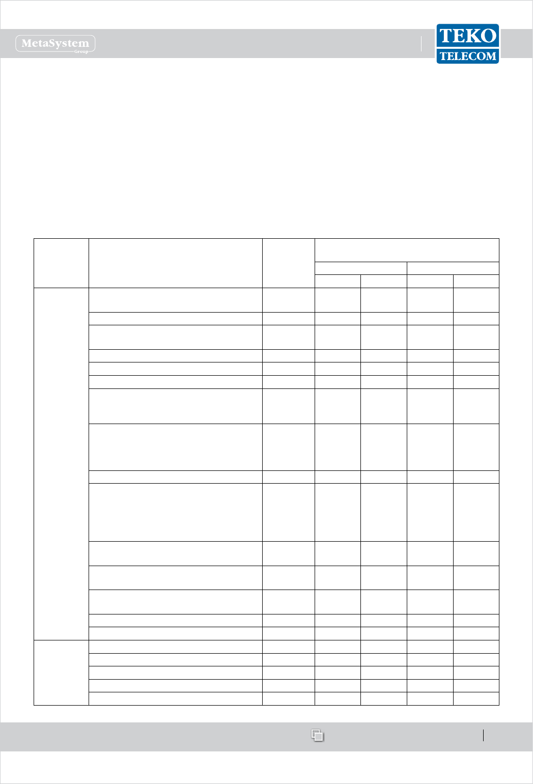
Compliance with the Maximum Permissible Exposure (MPE) limits - Examples of minimum separation
distance calculation, based on the EN 50385
The following table summarizes the results of the calculations carried out assuming:
zero losses between the output connector of Teko Telecom equipment and the input connector of the antenna•
maximum gain estimated for outdoor Antenna Gi = 19dBi (for each band)•
maximum gain estimated for indoor Antenna Gi = 7dBi (for each band)•
no co-location or operation• in conjunction with any other antenna or transmitter.
Please note
The following table is not meant to represent the actual compliance distance from a particular Teko Telecom Optical System or Modular
Repeater, being antennas, cables, and other RF components not provided with Teko Telecom equipment.
The actual compliance distance from a particular equipment can be calculated in the nal installation phase only - when antenna, cables and
other RF components specications are available.
Equipment Type Maximum
Output
Power
Minimum separation distance between a person and
the antenna in order to comply with MPE limits [m]
Indoor installation Outdoor installation
E=6 [V/m] E=20 [V/m] E=6 [V/m] E=20 [V/m]
Remote Unit
and
Service Front
End (TSFE)
Low Power Single band Remote Units•
Medium Power EGSM band Remote Unit•
29dBm 1.8 0.6 7.1 2.3
Medium Power DCS band Remote Unit 31dBm 2.2 0.7 8.9 2.8
Low Power Dual band Remote Units•
Medium Power UMTS band Remote Unit•
32dBm 2.5 0.8 10.1 3.2
Triband Low Power Remote Units 33.8dBm 3.1 1.0 12.3 3.9
Dual band Medium Power Remote Units 34.6dBm 3.4 1.1 13.4 4.2
Medium Power Triband Remote Units 35.6dBm 3.8 1.5 15.2 4.8
Low Power 5-band Remote Unit•
High Power TETRA Remote Unit•
High Power TETRA Service Front End•
36dBm 4.0 1.3 15.9 5.0
High Power Single band Remote Units (LTE800 •
or EGSM or DCS or UMTS)
High Power Service Front End (LTE800 or EGSM •
or DCS or UMTS or LTE2600)
40dBm 6.3 2.0 25.1 8.0
High Power Single band Remote Unit (LTE2600) 41dBm 7.1 2.2 28.1 8.9
High Power Dual band Remote Units (LTE800 •
and/or EGSM and/or DCS and/or UMTS)
Very High Power Single band Remote Units•
Very High Power Service Front End (LTE800 or •
EGSM or DCS or UMTS)
43dBm 8.9 2.8 35.6 11.2
High Power Dual Band Remote Units (LTE800 or
EGSM or DCS or UMTS with LTE2600)
43.5dBm 9.5 3.0 37.7 11.9
High Power Tri Band Remote Units (LTE800 and/or
EGSM and/or DCS and/or UMTS)
44.7dBm 10.9 3.5 43.6 13.8
High Power Tri Band Remote Units (LTE800 or
EGSM or DCS or UMTS with LTE2600)
45.1dBm 11.4 3.6 45.3 14.3
Very High Power Dual Band Remote Units 46dBm 12.6 4.0 50.3 15.9
Very High Power Tri Band Remote Units 47.8dBm 15.5 4.9 61.6 19.5
Donor Front
End
(TDFE)
Single Band TETRA Donor Front End 21dBm 0.7 0.2 2.8 0.9
Single Band EGSM Donor Front End 23dBm 0.9 0.3 3.6 1.1
Single Band DCS Donor Front End 25dBm 1.1 0.4 4.5 1.4
Single Band LTE 800 or LTE2600 Donor Front End 26dBm 1.3 0.4 5.0 1.6
Single Band UMTS Donor Front End 27dBm 1.4 0.5 5.6 1.8

www.tekotelecom.it
www.tekotelecom.it
SIRIUS: Teko Telecom Modular Coverage and Capacity System
Let us repeat !
Doc ID Number 91 080 0781 - Rel. 04 page 8
english
Operation is subject to the following conditions: (1) this device may not cause interference, and (2) this device must
accept any interference, including interference that may cause undesired operation of the device.
Changes or modications not expressly approved by the party responsible for compliance could void the user’s
authority to operate the equipment.
The antenna(s) used for this transmitter must be installed to provide a separation distance of:
at least 50cm for Low Power Remote Units family in Tri-Band system (with 8dB of maximum antenna gain for operating bands lower than •
1.5GHz and 11dB for operating bands higher than 1.5GHz),
at least 50cm for Low Power Remote Units family in Six-Band system (with 4.5dB of maximum antenna gain for operating bands lower •
than 1.5GHz and 6.5dB for operating bands higher than 1.5GHz),
at least 150cm for Very High Power Remote Units family in Tri-Band System (with 3.5dB of maximum antenna gain for operating bands •
lower than 1.5GHz and 6.5dB for operating bands higher than 1.5GHz)
at least 50cm for Donor Front End family (with 15.5dB of maximum antenna gain for operating bands lower than 1.5GHz and 19dB for •
operating bands higher than 1.5GHz),
at least 150cm for Very High Power Amplier radio module, equipped inside Service Front End family and Very High Power Remote •
Units family (with 8dB of maximum antenna gain for operating bands lower than 1.5GHz and 11.5dB for operating bands higher than
1.5GHz)
from all persons assuming no co-location or operating in conjuction with any other antenna or transmitter.
Specications of antennas, cables, RF components, etc will be provided only in the nal installation phase, being the external antenna not
provided with equipment.
Equipment will be accessible only to maintenance men, that must switch it o before any maintenance operation.
Teko Telecom Coverage and Capacity Systems Technical Handbook
© Copyright 2010-2012 Teko Telecom S.p.A. All rights reserved.
The content of this manual is for informational use only. Information and specications regarding the products described in this document
are subject to change without notice. The images shown in this document are for illustrative purposes only.
Teko Telecom shall not be liable for technical or editorial errors contained in this manual.
www.tekotelecom.it
www.tekotelecom.it
Let us repeat !
english
Doc ID Number 91 080 0781 - Rel. 04
1.General Description
1.General Description
1.General Description
1.General Description
1.General Description
1.General Description
1.General Description
1.General Description
1.General Description
1.General Description
1.General Description
1.General Description
1.General Description
1.General Description
1.General Description
1.General Description
1.General Description
1.General Description
1.General Description
1.General Description
1.General Description
1.General Description
1.General Description
1.General Description
1.General Description
1.General Description
1.General Description
SIRIUS: Teko Telecom Modular Coverage and Capacity System

www.tekotelecom.it
www.tekotelecom.it
SIRIUS: Teko Telecom Modular Coverage and Capacity System
Let us repeat !
Doc ID Number 91 080 0781 - Rel. 04 page 10
english
Teko Telecom Modular Coverage and Capacity System - General 1.
Description
Teko Telecom Coverage and Capacity Systems are exible multi-band multi-operator Systems
that provide a wide range of solutions to extend both indoor and outdoor cellular coverage
in shadow areas -where the RF signal is not available- and to increase capacity in indoor and
outdoor hot spots -where the operators need dedicated coverage.
Modular design is a key feature of Teko Telecom Systems: it oers exible conguration
options to build the most suitable solution for any coverage need.
SIRIUS
Stand-alone Modular Repeaters, Optical Systems as well as integrated solutions share a unique
common platform: SIRIUS.
SIRIUS includes a wide range of active and passive components that can be assembled in a
variety of ways in order to provide easy to set-up, maintain, and upgrade products operating
in the 380 to 2700MHz frequency range.
SIRIUS components can be used in dierent Systems with dierent functionalities to meet
present needs and to allow system adaptation to changing conditions, always assuring
optimized performances.
Teko Telecom Master Unit is the core of SIRIUS modular design: it is a versatile modular rack-
based platform that controls the whole Coverage System and, depending on its components
conguration, is able to provide:
the RF interface towards the signal source (BTS, Node B, Repeater),•
the RF interface towards Service Antennas/leaky cable,•
the optical interface towards up to 144 Remote Units.•
This technical handbook describes the components of SIRIUS and how these components can
be assembled to provide Optical Systems and Modular O-air Repeaters to improve coverage
in dierent environments.

www.tekotelecom.it
www.tekotelecom.it
SIRIUS: Teko Telecom Modular Coverage and Capacity System
Let us repeat !
Doc ID Number 91 080 0781 - Rel. 04 page 11
english
Components1.1
The components of SIRIUS can be grouped in the following categories:
Modules providing the RF interface towards the signal source1.
Point of Interface (POI) module:• is the single-band/single-operator interface towards
a BTS or NodeB. The Point of Interface module is connected to the signal source via
coaxial cable.
Digital Donor Front End Module: • is the single-band/single-operator interface towards
a Donor Antenna, providing a connection to a BTS or NodeB over an air link.
Equipment extending coverage / distributing capacity2.
Service Front End:• is the single-band/multi-operator interface towards a Service
Antenna. It provides wireless signal to the area to be covered (Modular Repeaters).
In Optical Systems the Service Front End can be used to extend coverage to the area
close to the Master Unit site.
Remote Unit:• is the multi-band/multi-operator equipment used in Optical Systems to
distribute wireless signal throughout the area to be covered (extensive areas coverage/
active DAS).
Modules providing the optical interface towards Remote Units3.
Fiber Optic Transmitter/Receiver Modules• are the optical interface between Master
Unit and Remote Units: they provide RF-to-Optical/Optical-to-RF conversion.
Master and Slave Point to Point Modules • perform the RF-to-Optical/Optical-to-RF
conversion required by the optical point to point link connecting RF Interface modules
to distant Fiber Optic Transmitter/Receiver Modules. The optical point to point link
allows a separation distance -up to 20km- between RF Interface modules and Fiber
Optic Transmitter/Receiver Modules.
Passive Modules providing distribution and ltering4.
Our passive components provide RF distribution and ltering.
The 4-way Combiner/Splitter can be used to manage up to 4 RF interface modules
operating in the same band; several models of Triplexers with built-in 1:4 Splitter/Combiner
are available to distribute signals operating over up to 3 dierent bands. The multiplexers
distribute signals operating over multiple dierent bands - up to 5 (pentaplexer); up to 6
(esaplexer).
Due to the exible conguration options of Teko Telecom Coverage and Capacity Systems,
the same passive components can be used for dierent purposes.
The • 4-way Combiner/Splitter can be used to manage either up to 4 RF interface

www.tekotelecom.it
www.tekotelecom.it
SIRIUS: Teko Telecom Modular Coverage and Capacity System
Let us repeat !
Doc ID Number 91 080 0781 - Rel. 04 page 12
english
modules, operating in the same band (Multi-Operator Systems) or up to 4 Fiber
Optic Modules (Fiber Optic Transmitter/Receiver Modules or Master Point to Point
Modules).
The • Band Splitter/Combiner (Triplexer) with built-in 1:4 Splitter/Combiner
can be used to manage up to 3 RF interface modules or Service Front End subracks,
operating in dierent bands, and up to 4 Fiber Optic Modules. It can also manage
up to 3 four-way splitter/combiner modules each connected to multiple RF interface
modules, operating in the same band, and up to 4 Fiber Optic Modules.
Modules for the management of the System5.
The • Supervision Module allows the management of the whole Coverage System.
The • Alarm Module is an optional module that can be equipped to increase the number
of supported external alarms.
Power Supply Modules6.
The Coverage and Capacity Systems can be equipped with either AC (Universal mains,
85÷264Vac, 50-60Hz) or DC (-72÷-36Vdc) Power Supply modules.
Subracks hosting the System modules7.
Both active and passive subracks are available.
Active subracks• are provided with a backplane that allows the management and
power supply of active modules.
Passive subracks• are used to host passive modules that do not require power nor
management to function. Passive Subracks allow a reduction in the cost of the whole
system.
Forced-air cooling Subrack8.
A forced-air cooling subrack is available to ensure the air ow required for proper cabinet
installed equipment operation.
Rack cabinets for hosting the System Subracks (indoor installation) and cabinets for Outdoor
installation are also available.
A detailed description of each Component of Teko Telecom Modular Coverage and Capacity
System is provided in the following paragraphs.
www.tekotelecom.it
www.tekotelecom.it
SIRIUS: Teko Telecom Modular Coverage and Capacity System
Let us repeat !
Doc ID Number 91 080 0781 - Rel. 04 page 13
english
Modules providing the RF interface towards the signal source1.1.1
Point Of Interface Modules•
Point of Interface modules are used in Optical Systems to interface any kind of operator signal
source -pico/micro/macro BTS or NodeB: each Point of Interface module is connected to a
single mobile operator/ mobile band signal source via coaxial cable.
Optical Systems can be equipped with one Point of Interface or more Point of Interface
modules to make multiple congurations available: single operator (single band / multi-band)
and multi-operator (single-band / multi-band).
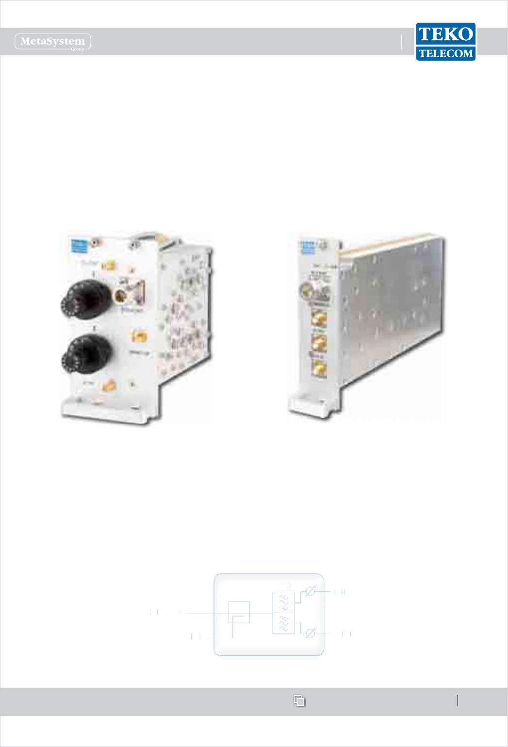
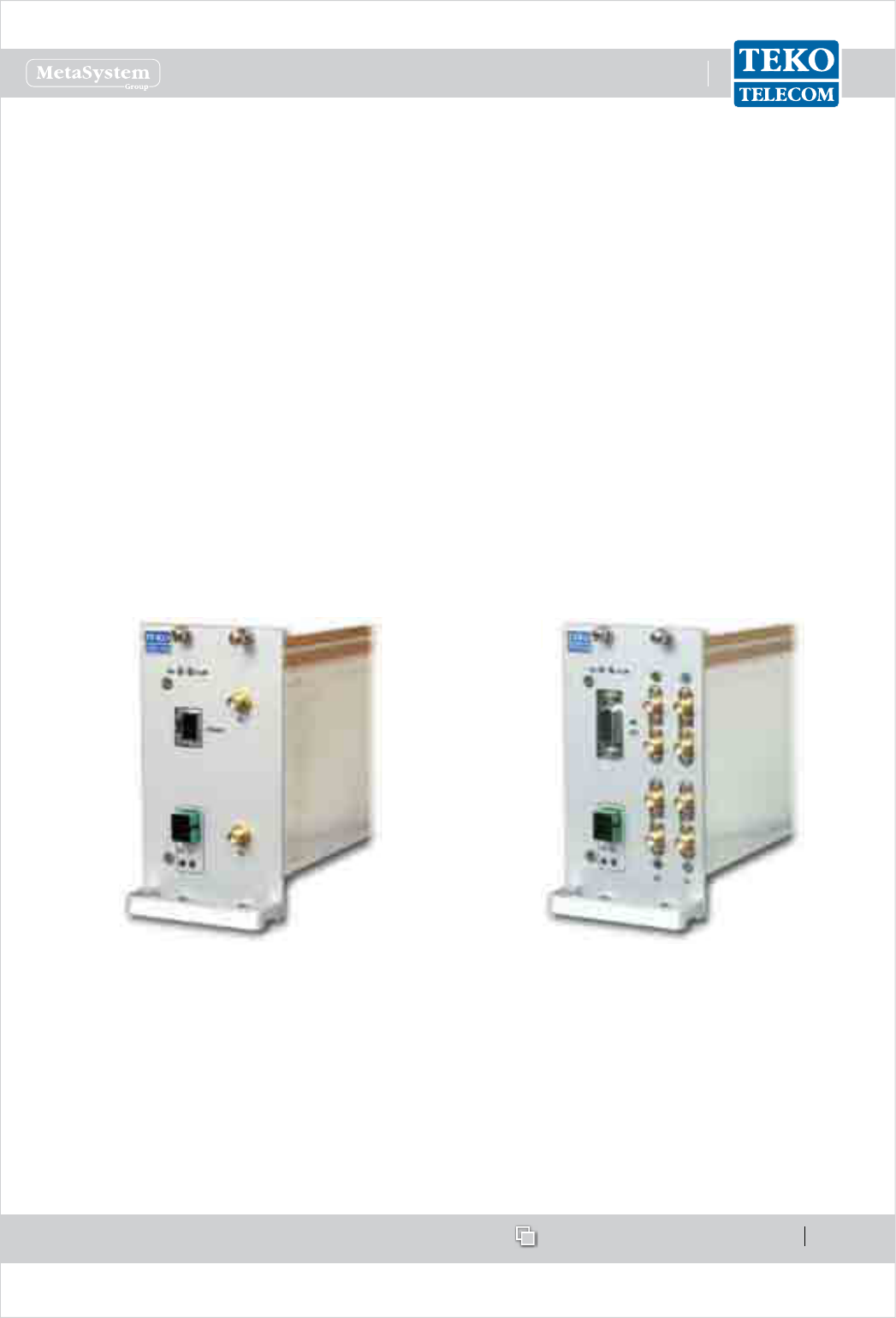
Passive Point Of Interface module (POI)
with rotary adjustable attenuators
Point Of Interface module (TAPOI) with
remote-controlled variable attenuators
Each Point of Interface module includes the duplexer, to separate/combine Downlink and
Uplink paths and two variable attenuators to make both Downlink and Uplink RF levels
separately adjustable.
A monitor port is available either for measurements or for external wireless modem
coupling.
Point Of Interface module block diagram
UL
DLDLDLDLDL
ULULULULUL
DLDLDLDLDL
-----
OUTOUTOUTOUTOUT
-IN-IN-IN-IN-IN
BTBTBTBTBT
S PORTS PORTS PORTS PORTS PORT
MONITMONITMONITMONITMONIT
OROROROROR

www.tekotelecom.it
www.tekotelecom.it
SIRIUS: Teko Telecom Modular Coverage and Capacity System
Let us repeat !
Doc ID Number 91 080 0781 - Rel. 04 page 14
english
Point of Interface modules with separate Downlink and Uplink ports (without built-in duplexer)
are available as option.
Teko Telecom Point of Interface modules can be equipped either with manually adjustable
attenuators (POI-x models) or with remote-controlled attenuators (TAPOI-x models).
POI modules
POI modules include two rotary adjustable attenuators to make Downlink and Uplink RF
levels manually adjustable within a range of either 30dB, with 1dB step, or 10dB, with 1dB
step (POI-A10 models).
TAPOI modules
TAPOI modules include two automated variable attenuators to adjust Downlink and Uplink
RF levels via the Coverage System Supervision Module (TSPV) and Management Tools (OMT
webpages, OMC software).
www.tekotelecom.it
www.tekotelecom.it
SIRIUS: Teko Telecom Modular Coverage and Capacity System
Let us repeat !
Doc ID Number 91 080 0781 - Rel. 04 page 15
english
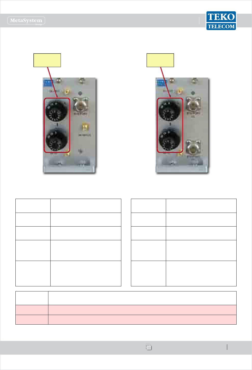
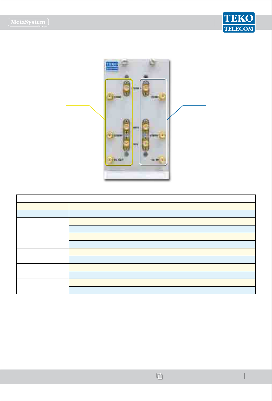
POI Modules Access Points•
Passive POI with built-in duplexer Passive POI without built-in duplexer
Adjustable
attenuators
Adjustable
attenuators
Label
(Connectors)
Description
DL-OUT Downlink path RF output
(SMA connector)
UL-IN Uplink path RF input (SMA
connector)
BTS PORT
RF connector (N type )
towards the signal source
(BTS, Node B or repeater)
MONITOR
Monitor port for
measurements or for external
wireless modem coupling
Label
(Connectors)
Description
DL-OUT Downlink path RF output
SMA connector
UL-IN Uplink path RF input SMA
connector
BTS PORT DL
Input RF connector from the
signal source - BTS, Node B
or repeater (N type)
BTS PORT UL
Output RF connector to the
signal source - BTS, Node B
or repeater (N type)
Adjustable
attenuators
Description
DL OUT Downlink path RF level adjustable attenuator (0÷30dB or 0÷10dB - 1 dB step)
UL IN Uplink path RF level adjustable attenuator (0÷30dB or 0÷10dB - 1 dB step)
www.tekotelecom.it
www.tekotelecom.it
SIRIUS: Teko Telecom Modular Coverage and Capacity System
Let us repeat !
Doc ID Number 91 080 0781 - Rel. 04 page 16
english
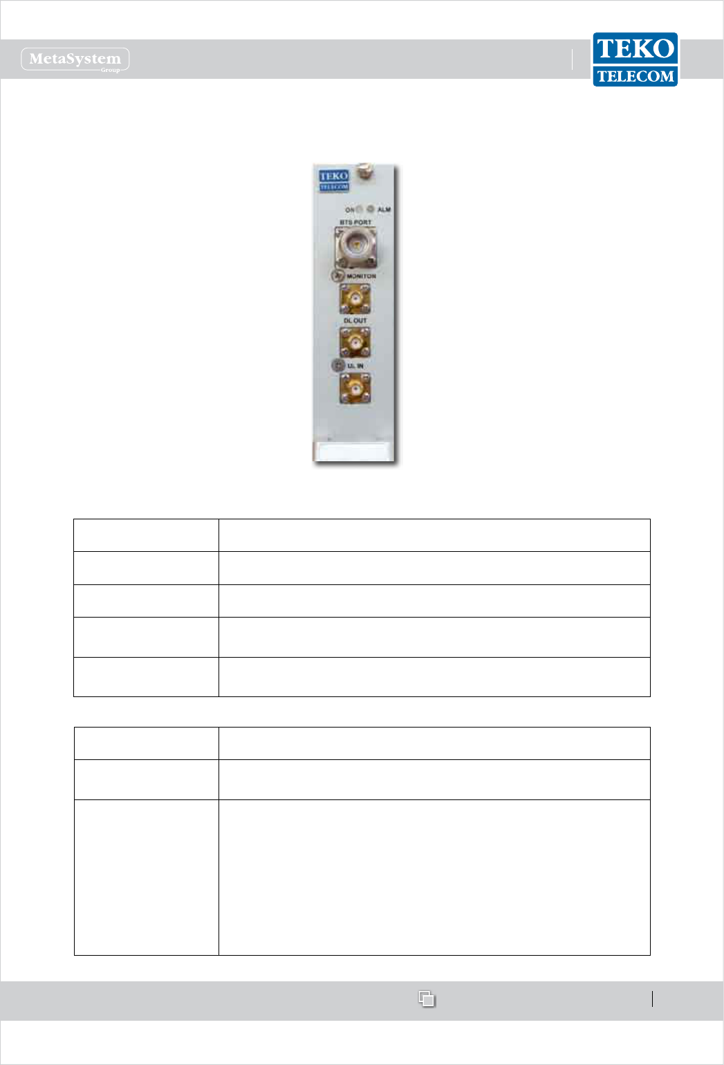
TAPOI Module Access Points•
TAPOI with built-in duplexer
Label (Connectors) Description
DL OUT Downlink path RF output (SMA connector)
UL IN Uplink path RF input (SMA connector)
BTS PORT RF connector (N type ) towards the signal source (BTS, Node B
or repeater)
MONITOR Monitor port for measurements or for external wireless
modem coupling
Label (LEDs) Description
ON TAPOI Module operating status green LED
ON when power supply is present
ALM TAPOI Module alarm status LED:
OFF: regular operation
Blinking Orange: presence of active alarms with warning
severity level (4)
Orange: presence of active alarms with minor severity level (3)
Blinking Red: presence of active alarms with major severity
level (2)
Red: presence of active alarms with critical severity level (1)
www.tekotelecom.it
www.tekotelecom.it
SIRIUS: Teko Telecom Modular Coverage and Capacity System
Let us repeat !
Doc ID Number 91 080 0781 - Rel. 04 page 17
english
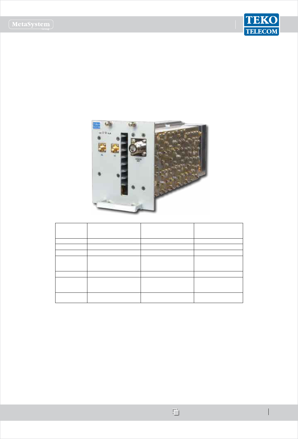
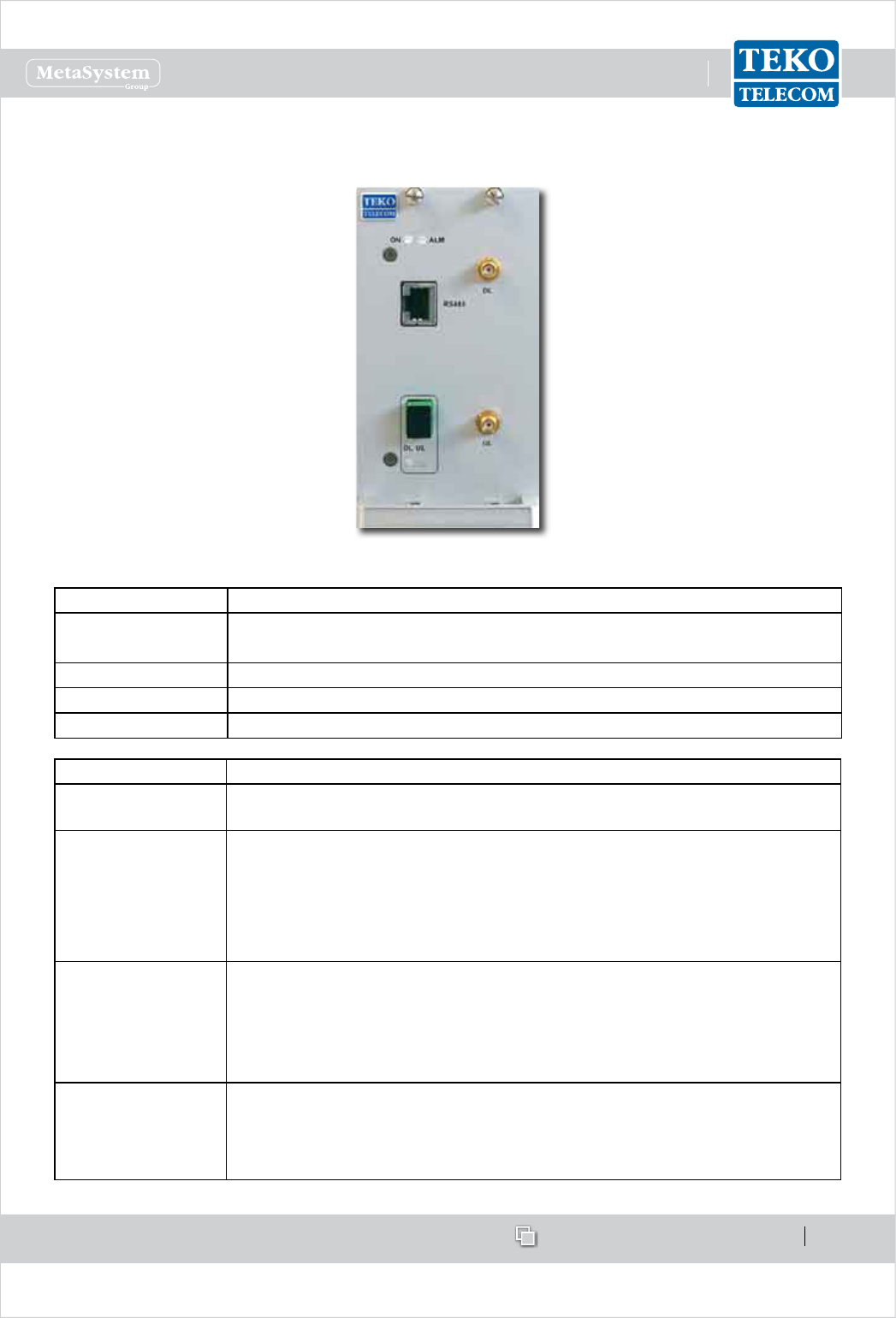
Teko Telecom Digital Donor Front End•
The Digital Donor Front End Module is the single-band/single-operator System RF interface
towardsaDonorAntenna.NophysicalconnectionsarerequiredbetweentheDFEandthecellular
network:theDonorAntennaprovidestheconnectiontoaBTSorNodeBoveranairlink.
CoverageSystemscan be equippedwithone or moreDonor FrontEnd modules to make
multiple congurations available: single operator (single band / multi-band) and multi-
operator(single-band/multi-band).
TEKO
TELECOM
CODE
UPLINK
OPERATING
FREQUENCY BAND
DOWNLlNK
OPERA TING
FREQUENCY BAND
Modulation
TDFE-7SL 698÷716MHz 728÷746 MHz LTE (QAM, QPSK)
TDFE-7SH 776÷787MHz 746÷757 MHz LTE (QAM, QPSK)
TDFE-8S806 ÷824 MHz 851÷869 MHz iDEN
TDFE-8A824 ÷849 MHz 869÷894 MHz
GSM-EDGE-TDMA-
CDMA-WCDMA-LTE
(QAM, QPSK)
TDFE-9S896 ÷902 MHz 935÷941 MHz iDEN
TDFE-191850 ÷1915 MHz1930 ÷1995 MHz
GSM-EDGE-TDMA-
CDMA-WCDMA-LTE
(QAM, QPSK)
TDFE-AW1710 ÷1755 MHz2110 ÷2155 MHz CDMA-WCDMA-LTE
(QAM, QPSK)
DigitalDonorFrontEndModuleoperatingfrequencybandssummarytable
Asingle-bandsingle-operatormodularO-airRepeatercanbesetupcombiningaDigital
DonorFrontEndModuleandaServiceFrontEnd(TekoTelecomsingle-band/multi-operator
interfacetowardsaServiceAntenna).Upto4DonorFrontEndModulescanbeconnectedto
asingleServiceFrontEndtoprovideasingle-band4-operatormodularO-airRepeater.
DigitalDonorFrontEndModulescanalsobeusedtodriveOpticalSystems:theDigitalDonor
FrontEndModuleallowsOpticalSystemstobedrivenwithouttheneedofadedicatedBTSor
NodeB.Adonorantennapicks-upthesignalandtheOpticalSystemactsasarepeaterwith
distributedServiceantennasconnectedtotheRemoteUnits.ServiceFrontEndsubrackscan
www.tekotelecom.it
www.tekotelecom.it
SIRIUS: Teko Telecom Modular Coverage and Capacity System
Let us repeat !
Doc ID Number 91 080 0781 - Rel. 04 page 18
english
beconnectedtoDFEmodulestoprovidecoveragetotheareanexttotheMasterUnitsite.
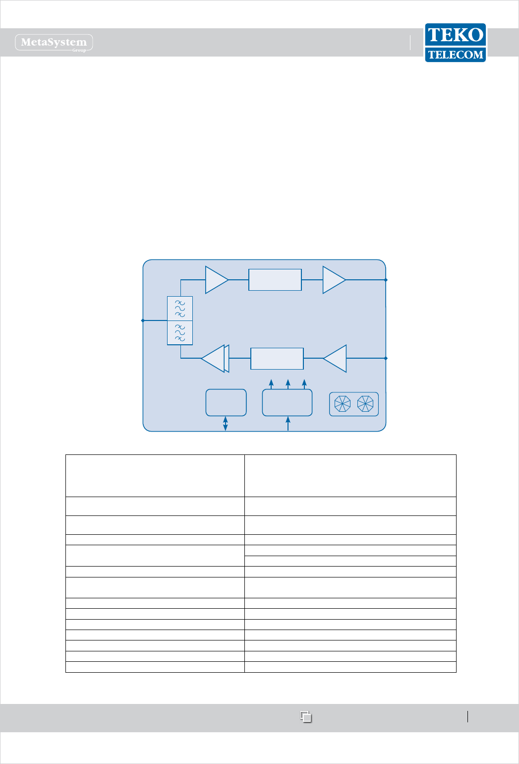
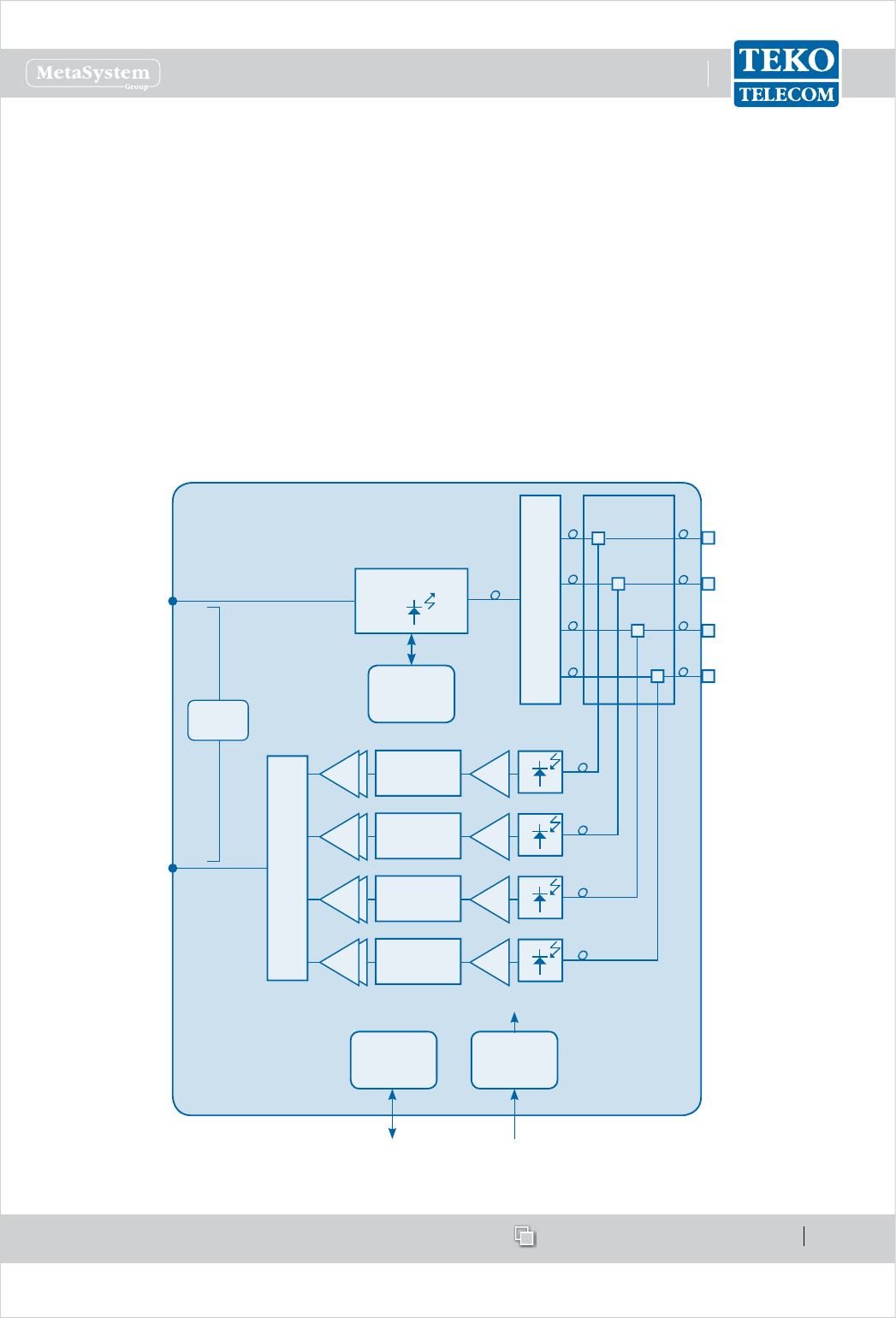
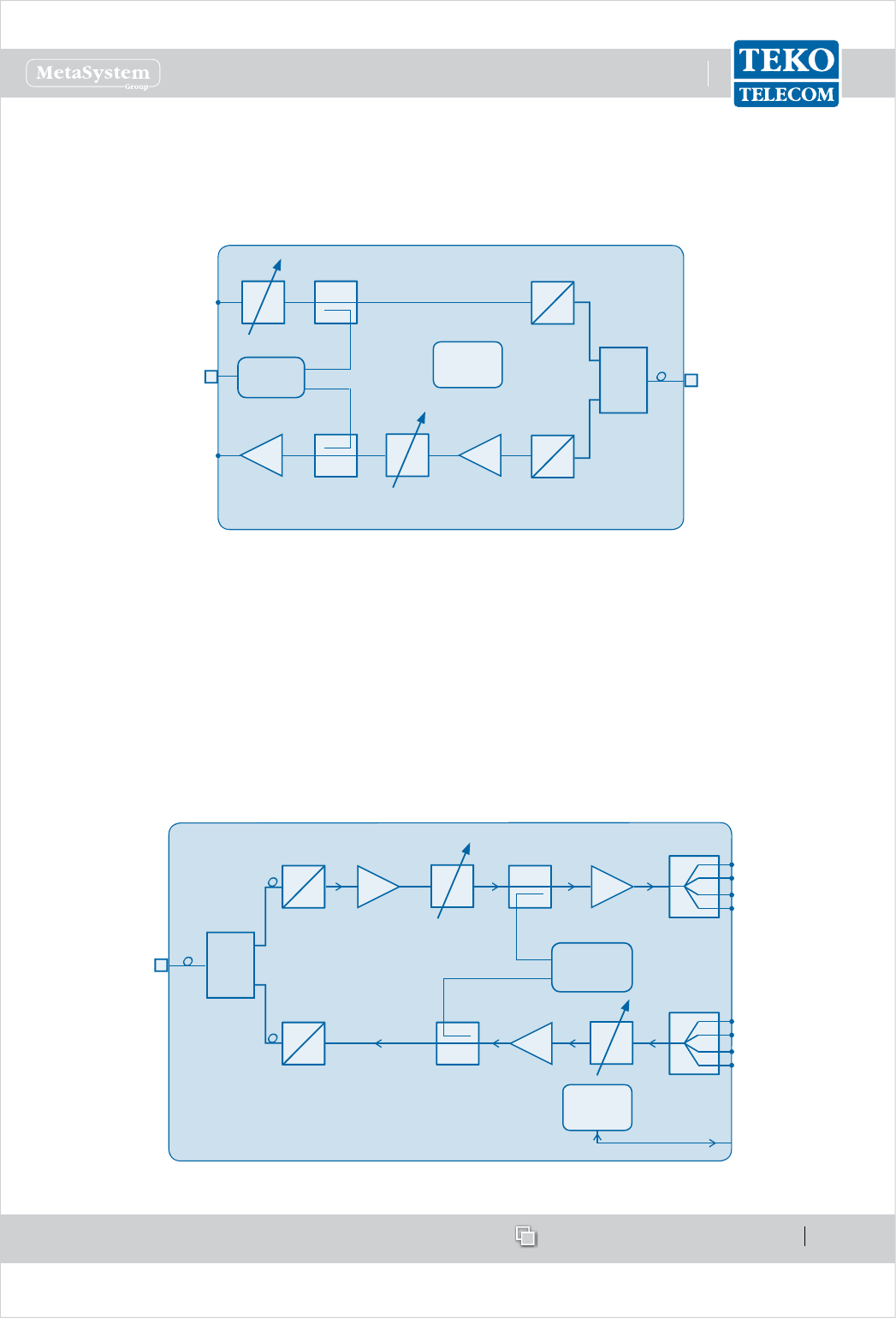
EachDFEmodulehoststheduplexer,tobeconnectedtotheDonorAntennatoseparate/
combinedownlinkanduplinkpaths.
IndownlinkthesignalfromtheDonorAntennaispreampliedbyaLowNoiseAmplierand
convertedintoanIFsignalbyadownconverter.Theselectionofthebandoffrequenciesor
channelstobeextendedishandledbyadigitallter.Thedigitalltercanmanage1variable
bandor2variablesub-bands.AnupconverterconvertstheIFsignalintotheRFoutputsignal.
InuplinkthesignalfromtheServiceFrontEndSubrackorfromtheOpticalSystemisconverted
intoanIFsignalbyadownconverter,lteredandre-convertedintoanRFsignal,ampliedby
apoweramplierandre-transmittedtothesignalsource.
DLRF
Out
ULRF
In
Donor
Antenna
Port
Duplexer
μP DC/DC
+12V +1.8V+3.3V
28÷30VDC
RS485
FANS
DigitalFilter
DigitalFilter
PA
LNA
DigitalDonorFrontEndModuleblockdiagram
COMMERCIAL CODES TDFE-7SL; TDFE-7SH
(TDFE- Teko Telecom band code)TDFE-8S; TDFE-8A; TDFE-9S
For UL/DL Operating bands please refer to TDFE-19; TDFE-AW
the Operating frequency bands Summary Table
Down-LinkOutput Power: 10 dBm
Gain: 63 dBm
Up-LinkOutput Power: 26 dBm
Gain: 64 dBm
Number of variable sub-bandsUp to 2
Variable sub-band bandwidth 200kHz to 25MHz (100kHz step) -1 sub-band
200kHz to 14.2MHz (100kHz step) -2 sub-bands
Processed Band up to 35MHz
Attenuation range on each sub-band
(relative to set RF gain) 0÷30dB (0.5dB step) independent on each sub-band
Connector to the Donor Antenna N (f)
CoolingActive (with fans)
Power supply28÷30 Vdc
Power Consurnption 37 W
Operatingtemperature range -5°C up to +55°C (+23°F up lo + 131°F)
Weight ~ 3,5 Kg (7.7Ib)
Dimensions 3HE / 21TE
DigitalDonorFrontEndModulestechnicalspecications
www.tekotelecom.it
www.tekotelecom.it
SIRIUS: Teko Telecom Modular Coverage and Capacity System
Let us repeat !
Doc ID Number 91 080 0781 - Rel. 04 page 19
english
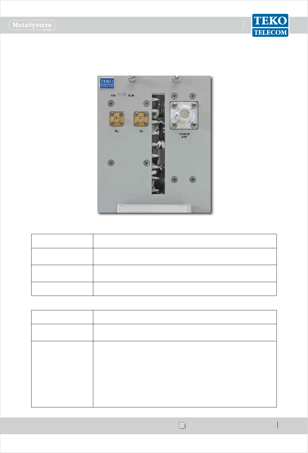
Digital Donor Front End Module Access Points
Label (Connectors) Description
DL Downlink path RF output (SMA connector) to Service Front
End or Fiber Optic Modules
UL Uplink path RF input (SMA connector) from Service Front End
or Fiber Optic Modules
DONOR ANT Donor Antenna Port (N type connector)
Label (LEDs) Description
ON Digital Donor Front End Module operating status green LED:
ON when power supply is present
ALM
Digital Donor Front End Module alarm status LED:
OFF: regular operation
Blinking Orange: presence of active alarms with warning
severity level (4)
Orange: presence of active alarms with minor severity level (3)
Blinking Red: presence of active alarms with major severity
level (2)
Red: presence of active alarms with critical severity level (1)
www.tekotelecom.it
www.tekotelecom.it
SIRIUS: Teko Telecom Modular Coverage and Capacity System
Let us repeat !
Doc ID Number 91 080 0781 - Rel. 04 page 20
english
Equipment extending coverage / distributing capacity1.1.2
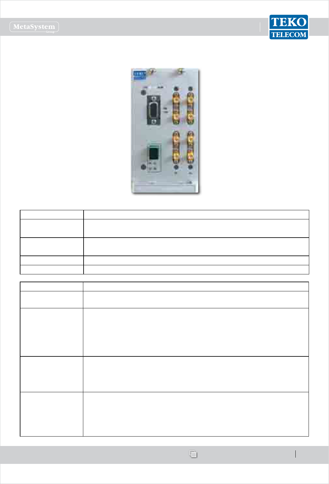
Teko Telecom Service Front End•
Teko Telecom Service Front End Subrack is a single-band/multi operator equipment, driven
by Digital Donor Front End Modules and connected to a Service Antenna to provide wireless
signal to the area to be covered. The equipment is available in four dierent power classes:
Very High, High, Medium and Low.
A single-band single-operator modular O-air Repeater can be set-up combining a Digital
Donor Front End Module and a Service Front End. Up to 4 Donor Front End Modules can
be connected to a single Service Front End subrack to provide a single-band 4-operator
Repeater.
The Service Front End subrack can also be used in Optical Systems to provide coverage to the
area adjoining the Master Unit site.
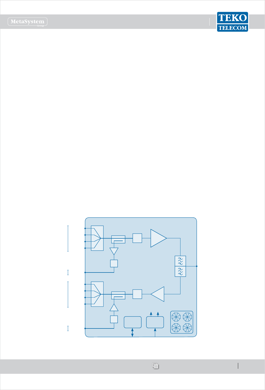
The SFE 19”/2U subrack hosts the duplexer, to be connected to the Service Antenna to
separate/combine Downlink and Uplink paths.
In Downlink the signals from the Donor Front-End Modules are combined and amplied by a
Power Amplier.
In Uplink, the RF signal from the Service antenna is amplied by a Low Noise Amplier (LNA)
and split to feed up to 4 Donor Front-End Modules.
Auxiliary ports are available to drive an Optical System.
PA
DL in1
Service
Antenna
Port
Duplexer
P DC/DC
+3.3V +5V
28÷30VDCRS485
Digital
Attenuator
DL in2
DL in3
DL in4
DL out
LNA
UL out1 Digital
Attenuator
UL out2
UL out3
UL out4
UL in
Digital
Attenuator
Digital
Attenuator
4:1
4:1
FANS
From DFEs
To DFEs
To Optics
From Optics
Service Front End block diagram
www.tekotelecom.it
www.tekotelecom.it
SIRIUS: Teko Telecom Modular Coverage and Capacity System
Let us repeat !
Doc ID Number 91 080 0781 - Rel. 04 page 21
english
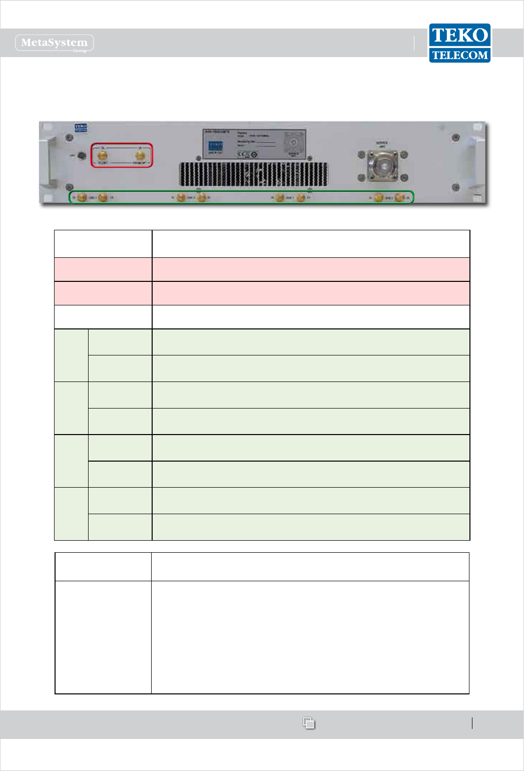
Service Front End Access Points
Label
(Connectors)
Description
DL TO OPT Downlink path RF output (SMA connector) - to Optics
UL FROM OPT Uplink path RF input (SMA connector) - from Optics
SERVICE ANT Service Antenna Port (N type )
DFE1
DL Downlink path RF input (SMA connector) - from Digital Donor
Front End 1
UL Uplink path RF output (SMA connector) - to Digital Donor Front
End 1
DFE2
DL Downlink path RF input (SMA connector) - from Digital Donor
Front End 2
UL Uplink path RF output (SMA connector) - to Digital Donor Front
End 2
DFE3
DL Downlink path RF input (SMA connector) - from Digital Donor
Front End 3
UL Uplink path RF output (SMA connector) - to Digital Donor Front
End 3
DFE4
DL Downlink path RF input (SMA connector) - from Digital Donor
Front End 4
UL Uplink path RF output (SMA connector) - to Digital Donor Front
End 4
Label
(LEDs)
Description
LED
Service Front End subrack general operating status LED
Green: no alarm
Blinking Orange: presence of active alarms with warning
severity level (4)
Orange: presence of active alarms with minor severity level (3)
Blinking Red: presence of active alarms with major severity
level (2)
Red: presence of active alarms with critical severity level (1)
www.tekotelecom.it
www.tekotelecom.it
SIRIUS: Teko Telecom Modular Coverage and Capacity System
Let us repeat !
Doc ID Number 91 080 0781 - Rel. 04 page 22
english
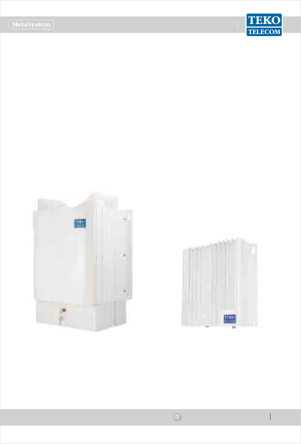
Teko Telecom Remote Units•
Remote Units are used in Optical Systems to distribute wireless signals throughout the area
to be covered. They are connected to the Fiber Optic Transmitter/Receiver Modules equipped
in the Master Unit.
Remote Units are equipped with the Fiber Optic Receiver and Transmitter module (for Optical
to RF and RF to Optical conversion), power ampliers and ltering.
They can be Single or Multi-band with four dierent RF power classes: Very High, High,
Medium and Low.
Remote Units with dierent power classes can be driven simultaneously by the same Master
Unit to distribute capacity or extend coverage into dierent locations at the same time.
Very High, High and Medium Power Remote Units are equipped in a weatherproof IP66
case. Low Power Remote Units are equipped in an IP32 case; a protection kit, providing IP66
protection degree, is available as option for installation in harsh environments.
Single, Dual or Tri-band Very High, High and
Medium Power Remote Unit
Single band / Multi-band Low Power Remote
Unit
Please refer to Paragraph 1.2.2 for a detailed description of Remote Units.
www.tekotelecom.it
www.tekotelecom.it
SIRIUS: Teko Telecom Modular Coverage and Capacity System
Let us repeat !
Doc ID Number 91 080 0781 - Rel. 04 page 23
english
Modules providing the optical interface towards Remote Units1.1.3
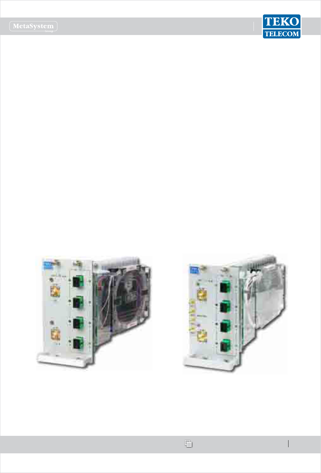
Fiber Optic Transmitter/Receiver Modules•
Fiber Optic Transmitter/Receiver Modules are the optical interface between Master Unit and
Remote Units: they provide RF-to-Optical/Optical-to-RF conversion. They are connected to
Remote Units via single mode optical bers, with Uplink and Downlink signals transmitted
over the same bre (Wavelength Division Multiplexing -WDM technology).
Dierent congurations are available: a single Fiber Optic Transmitter/Receiver Module can
be equipped with 1 Optical Transmitter and 1 Optical Receiver (10dB optical link budget, up
to 20km distance - 12.4 miles), or 1 Optical Transmitter split by 2 and 2 combined Optical
Receivers (10dB optical link budget, up to 20km distance- 12.4 miles), or 1 Optical Transmitter
split by 4 and 4 combined Optical Receivers (6dB optical link budget, up to 12km distance -
7.5 miles).
The Fiber Optic Transmitter/Receiver Module in 1:4 conguration can manage up to 4 Remote
Units.
The Fiber Optic Transmitter/Receiver Module in 1:1 conguration is able to drive up to 5
cascaded Remote Units with dierent wavelengths in Up-link.
Fiber Optic Transmitter/Receiver Module in 1:4
conguration
Fiber Optic Transmitter/Receiver Module (1:4
conguration) with monitor for E9-1-1 service
The Fiber Optic Transmitter provides the RF to optical conversion (Downlink side): the module
RF section covers the 380 to 2200MHz band (TTRC models) or the 380 to 2700MHz band
www.tekotelecom.it
www.tekotelecom.it
SIRIUS: Teko Telecom Modular Coverage and Capacity System
Let us repeat !
Doc ID Number 91 080 0781 - Rel. 04 page 24
english
(TTRU models).
Fiber Optic Receivers convert uplink optical signals from Remote Units into RF. They operate
in the third window (Optical wavelength 1490 ÷ 1570 nm).
Each Fiber Optic module is controlled by a microprocessor which provides the following data
to the Supervision Module:
optical power received by each optical receiver, -
Downlink attenuator and Uplink attenuator attenuation setting (0 ÷ 15dB), -
received optical power alarms. -
An auto-levelling functionality (AGC) compensates up to 10dB optical link loss in order
to guarantee constant gain over dierent optical budgets. This feature simplies system
installation, makes commissioning quick and easy and avoids eld adjustments.
CONTROL
1:4
OPT
MODEM
4:1
P DC/DC
28÷30VDCRS485
PA DIGITAL
ATTENUATOR LNA
PA DIGITAL
ATTENUATOR LNA
PA DIGITAL
ATTENUATOR LNA
PA DIGITAL
ATTENUATOR LNA
DL RF
WDM
DL/UL 1
DL/UL 3
DL/UL 2
DL/UL 4
UL RF
LASER
Block diagram: Fiber Optic Transmitter/Receiver Module equipped with 1 Optical Transmitter split by 4 and 4
combined Optical Receivers (WDM technology)
www.tekotelecom.it
www.tekotelecom.it
SIRIUS: Teko Telecom Modular Coverage and Capacity System
Let us repeat !
Doc ID Number 91 080 0781 - Rel. 04 page 25
english
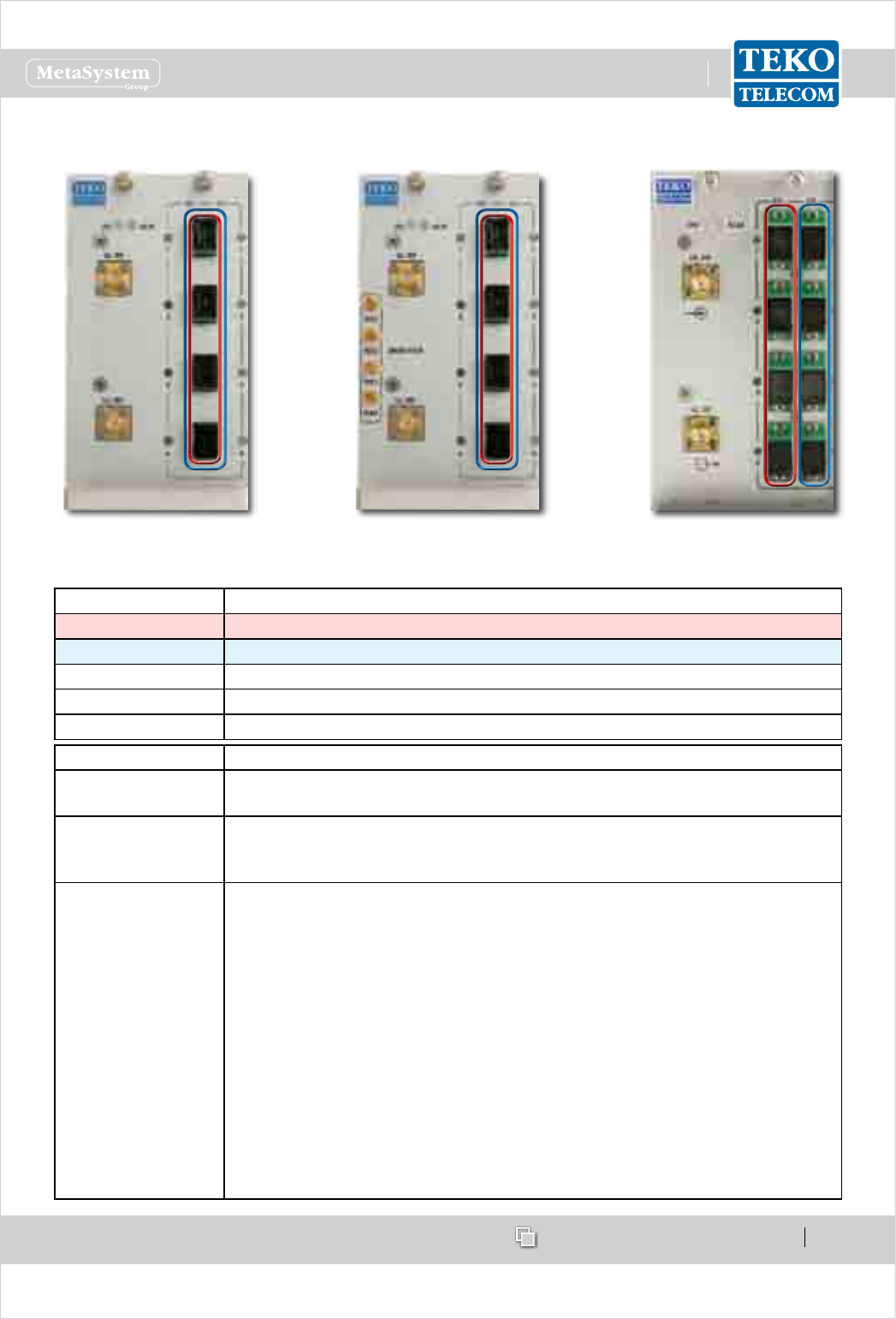
Fiber Optic Transmitter/Receiver Module Access Points
Label (Connectors) Description
DL Fiber Optic Transmitters (1 to 4) optical output connectors (SC-APC)
UL Fiber Optic Receivers (1 to 4) optical input connectors (SC-APC)
DL RF Fiber Optic Transmitter RF input SMA connector
UL RF Fiber Optic Receiver RF output SMA connector
Monitor RXn Monitor ports (RX1 to RX4) for E 9-1-1 service
Label (LEDs) Description
ON Fiber Optic Module operating status green LED
ON when power supply is present
ALM
Fiber Optic Module alarm status LED:
OFF: regular operation; BLINKING ORANGE/ORANGE: warning/minor;
BLINKING RED/RED: major/critical
DL UL
These LEDs describe the general operating status of Remote Units (1 to
4) connected to Fiber Optic Transmitters (DL) and Repeaters (UL) .
Each pair of DL/UL leds takes the same color as the general operating status
led of the Remote Unit connected to the optical connector, except when
a Laser Fault occurs in the Fiber Optic transmitter. If this fault occurs, all •
DL leds turn RED and the ALM Led switches on (RED).
a Low Optical Power alarm arises in the Fiber Optic receiver. If this alarm •
arises, the UL led turns RED and the ALM Led switches on (RED).
Each pair of DL/UL LEDs can be:
Green: Remote Unit status OK
Blinking Orange: presence of RU active alarms with warning severity level (4)
Orange: presence of RU active alarms with minor severity level (3)
Blinking Red: presence of RU active alarms with major severity level (2)
Red: presence of RU active alarms with critical severity level (1)
Fiber Optic Module 1:4
conguration
Fiber Optic Module 1:4
conguration - WDM
Fiber Optic Module 1:4
conguration - WDM with
Monitor for E9-1-1 service
www.tekotelecom.it
www.tekotelecom.it
SIRIUS: Teko Telecom Modular Coverage and Capacity System
Let us repeat !
Doc ID Number 91 080 0781 - Rel. 04 page 26
english
Master and Slave Point to Point Modules•
Master and Slave Point to Point Modules provide an optical point to point link allowing a
separation distance -up to 20km- between RF interface subracks and optical subracks.
The point to point link is suitable when the signal source (BTS, Node B, Repeater) is located
far from the area to be covered or when the same optical system provides coverage to several
separate buildings; in these applications the point to point link allows the transmission of
signals from/to a group of remote units over a single optical bre, thus providing a signicant
reduction in the number of ber optics running long distances.
The point to point link requires the RF interface subracks to be equipped with Master Point
to Point modules and the remote optical subracks to be equipped with Slave Point to Point
modules. The RF Interface subracks can be equipped with up to 4 Master Point to Point modules
for the management of up to 4 optical subracks, installed in dierent remote locations.
Master Point to Point Module Slave Point to Point Module
Each Master Point to Point Module is connected to a Slave Point to Point Module, equipped in
a remote optical subrack, via a single optical bre (single-mode SMR 9/125).
www.tekotelecom.it
www.tekotelecom.it
SIRIUS: Teko Telecom Modular Coverage and Capacity System
Let us repeat !
Doc ID Number 91 080 0781 - Rel. 04 page 27
english
Point to Point Modules (Master and Slave) perform the electrical-to-optical/optical-to-
electrical conversion required for the transmission of downlink and uplink signals over the
connecting optical bre.
1550nm
UL RF output
SMA (f)
DL RF input
SMA (f)
RS485
port
1310nm
E
O
E
O
Coupler
Coupler
Att.
Att.
DL/UL
optical SC/APC
connector
WDM
Modem
P
Master Point to Point Module block diagram
The Slave Point to Point module includes the 4-way splitter/combiner to manage up to 4 Fiber
Optic Transmitter/Receiver Modules. A built-in Supervision unit controls the remote optical
subrack, hosting the Slave Point to Point module, and all connected Remote Units.
The Coverage System Supervision Module communicates with the Slave Point to Point module
built-in Supervision unit via the single-mode optical ber connecting Master and Slave Point
to Point modules.
An RS232 port on the Slave Point to Point Module front panel allows local communication
with the built-in supervision.
1310nm
DL RF outputs
SMA (f)
connectors
UL RF inputs
SMA (f)
connectors
RS232
1550nm
O
E
O
E
Coupler
Att.
WDM Modem
P
DL/UL
optical SC/APC
connector
Att.
Slave Point to Point Module block diagram
www.tekotelecom.it
www.tekotelecom.it
SIRIUS: Teko Telecom Modular Coverage and Capacity System
Let us repeat !
Doc ID Number 91 080 0781 - Rel. 04 page 28
english
Master Point to Point Module Access Points
Master Point to Point Module
Label (Connectors) Description
DL UL Optical power input/output SC-APC connector (from/to Slave Point to
Point Module)
RS485 RJ45 connector for RS485 connection to the Supervision Module
DL RF input SMA connector (from the System RF Interface modules)
UL RF output SMA connector (to the System RF Interface modules)
Label (LEDs) Description
ON Master Point to Point Module operating status green LED:
ON when power supply is present
ALM Point to Point Module alarm status LED:
OFF: regular operation
Blinking Orange: presence of active alarms with warning severity level (4)
Orange: presence of active alarms with minor severity level (3)
Blinking Red: presence of active alarms with major severity level (2)
Red: presence of active alarms with critical severity level (1)
DL Fiber Optic Transmitter operating status LED:
BLINKING GREEN: the module is reaching its operating temperature
GREEN optical output power is available
ORANGE: warning: optical output power is degradated
RED: Laser Fault: no optical output power
UL
Fiber Optic Receiver operating status LED:
GREEN: +6dBm to -4dBm optical input power
YELLOW: -4dBm to -5dBm optical input power
RED: optical input power is >+6dBm or <-5dBm
www.tekotelecom.it
www.tekotelecom.it
SIRIUS: Teko Telecom Modular Coverage and Capacity System
Let us repeat !
Doc ID Number 91 080 0781 - Rel. 04 page 29
english
Slave Point to Point Module Access Points
Slave Point to Point Module
Label (Connectors) Description
DL UL Optical power input/output SC-APC connector (from/to Master Point to
Point Module
RS232 9-pole D-Sub RS232 connector for connection to an external modem
(Local Management)
DL RF output SMA connectors (to Fiber Optic Modules)
UL RF input SMA connectors (from Fiber Optic Modules)
Label (LEDs) Description
ON Master Point to Point Module operating status green LED:
ON when power supply is present
ALM Point to Point Module alarm status LED:
OFF: regular operation
Blinking Orange: presence of active alarms with warning severity level (4)
Orange: presence of active alarms with minor severity level (3)
Blinking Red: presence of active alarms with major severity level (2)
Red: presence of active alarms with critical severity level (1)
DL Fiber Optic Receiver operating status LED:
GREEN: +6dBm to -4dBm optical input power
YELLOW: warning: -4dBm to -5dBm optical input power
RED: alarm: optical input power is >+6dBm or <-5dBm
UL
Fiber Optic Transmitter operating status LED:
BLINKING GREEN: the module is reaching its operating temperature
GREEN optical output power is available
ORANGE: warning: optical output power is degradated
RED: : Laser Fault: no optical output power
www.tekotelecom.it
www.tekotelecom.it
SIRIUS: Teko Telecom Modular Coverage and Capacity System
Let us repeat !
Doc ID Number 91 080 0781 - Rel. 04 page 30
english
Passive Modules providing distribution and ltering1.1.4
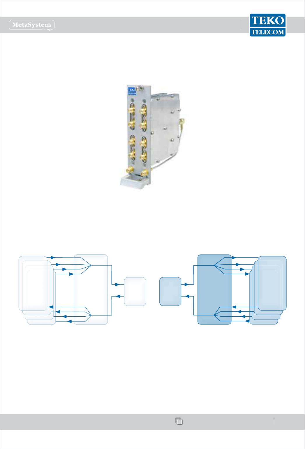
4-way Combiner/Splitter Module•
The 4-way Combiner/Splitter can be used to manage either up to 4 RF interface modules (POI
modules or DFE modules), operating in the same band (Multi-Operator Systems) or up to 4
Fiber Optic Transmitter/Receiver Modules.
4-way combiner (DL side) / 4-way splitter
(UL side) to manage up to 4 RF interface
modules operating in the same band
4-way splitter (DL side) / 4-way combiner
(UL side) to manage up to 4 Fiber Optic
Transmitter/Receiver Modules
RF INTERFACE
MODULES
(POI or DFE)
FIBER OPTIC
MODULES
4WAY
SPLITTER/COMBINER
4WAY
SPLITTER/COMBINER
DL
UL
DL
UL
RF INTERFACE
MODULE
(POI or DFE)
FIBER OPTIC
MODULE
4-way Combiner/Splitter module block diagrams
www.tekotelecom.it
www.tekotelecom.it
SIRIUS: Teko Telecom Modular Coverage and Capacity System
Let us repeat !
Doc ID Number 91 080 0781 - Rel. 04 page 31
english
4-way Combiner/Splitter Module Access Points
Label
(Connectors)
Description
UL
WHEN USED TO MANAGE MULTIPLE
RF INTERFACE MODULES
Up-link path output
SMA connectors (to RF
interface modules)
WHEN USED TO MANAGE MULTIPLE
FIBER OPTIC MODULES
Up-link path input
SMA connectors (from
optical sub-racks)
UL COMMON Up-link path input
SMA connector
Up-link path output
SMA connector
DL Down-link path input
connectors (from RF
interface modules)
Down-link path
output connectors
(to optical sub-racks)
DL COMMON Down-link path
output
Down-link path input
www.tekotelecom.it
www.tekotelecom.it
SIRIUS: Teko Telecom Modular Coverage and Capacity System
Let us repeat !
Doc ID Number 91 080 0781 - Rel. 04 page 32
english
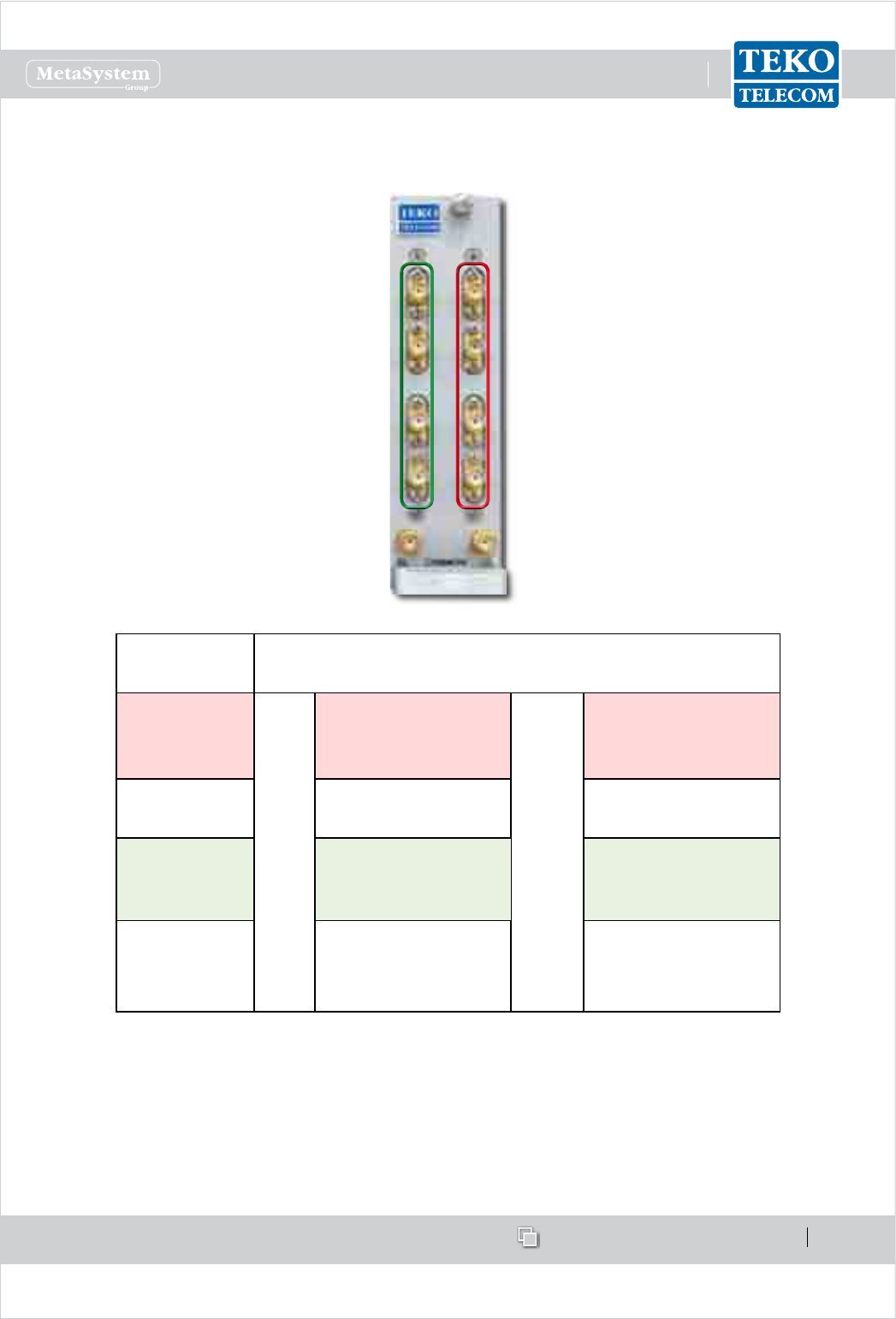
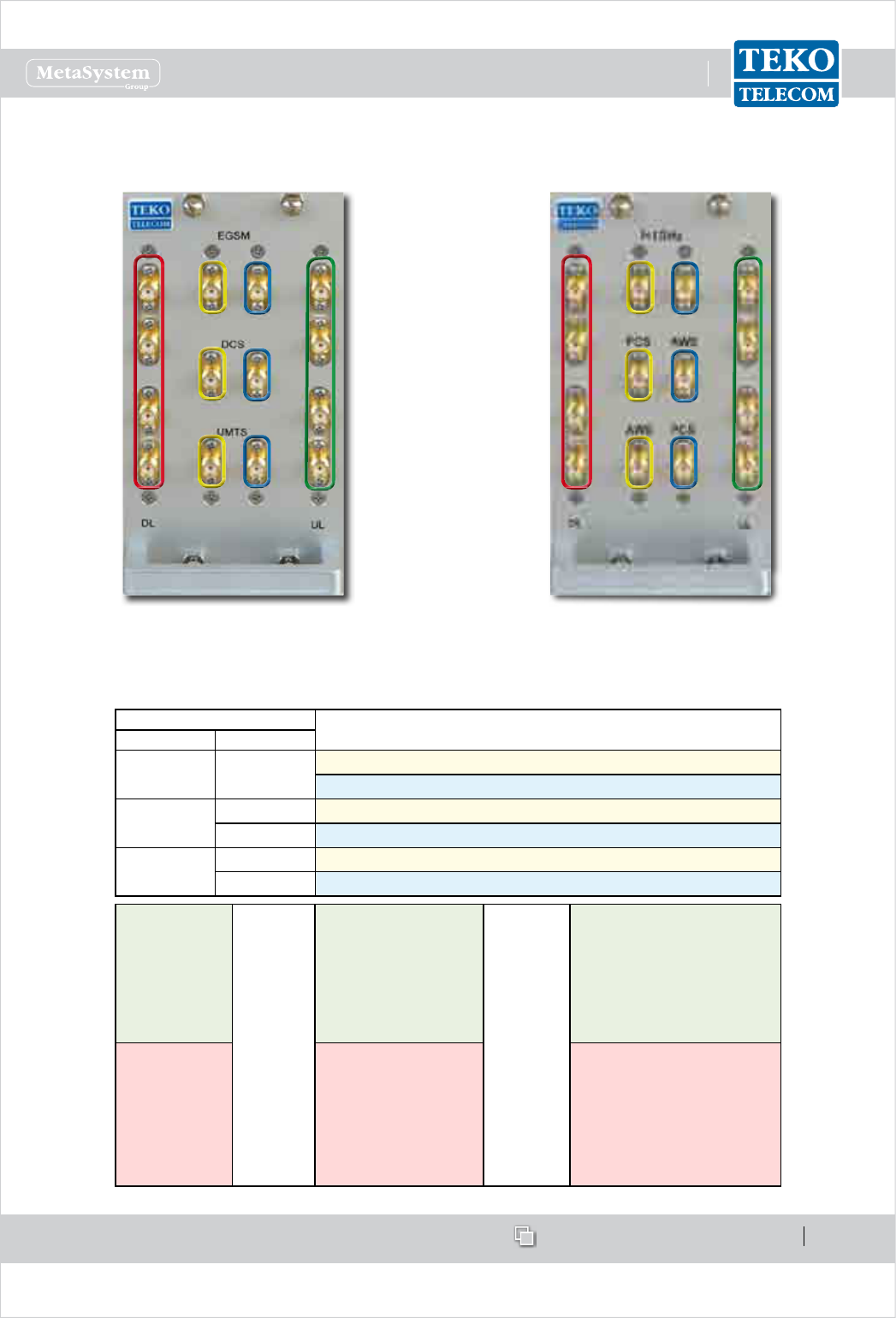
Triplexer (Band Splitter/Combiner) with built-in 4-way Combiner/Splitter•
The Triplexer is used in multi-band congurations to distribute signals operating in dierent
bands.
The module also includes a 4-way Splitter/Combiner to drive up to 4 Fiber Optic Transmitter/
Receiver Modules.
Several models of Triplexers, operating over dierent Uplink/Downlink frequency bands, are
available.
Example: EGSM, DCS, UMTS Triplexer with
built-in 4-way Combiner/Splitter
Example: AMPS, PCS, AWS Triplexer with built-in
4-way Combiner/Splitter
The triplexer can be used in Optical Systems to manage:
up to 3 RF interface modules operating in dierent bands and up to 4 Fiber Optic -
Transmitter/Receiver Modules, or
up to 3 Service Front End modules operating in dierent bands and up to 4 Fiber Optic -
Transmitter/Receiver Modules, or
up to 3 four-way splitter/combiner - used to manage multiple RF interface modules (up to -
4 for each band) - and up to 4 Fiber Optic Transmitter/Receiver Modules.
www.tekotelecom.it
www.tekotelecom.it
SIRIUS: Teko Telecom Modular Coverage and Capacity System
Let us repeat !
Doc ID Number 91 080 0781 - Rel. 04 page 33
english
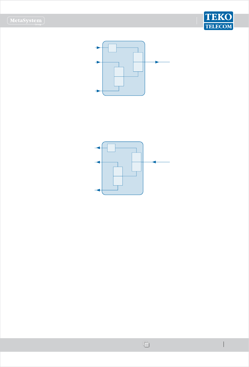
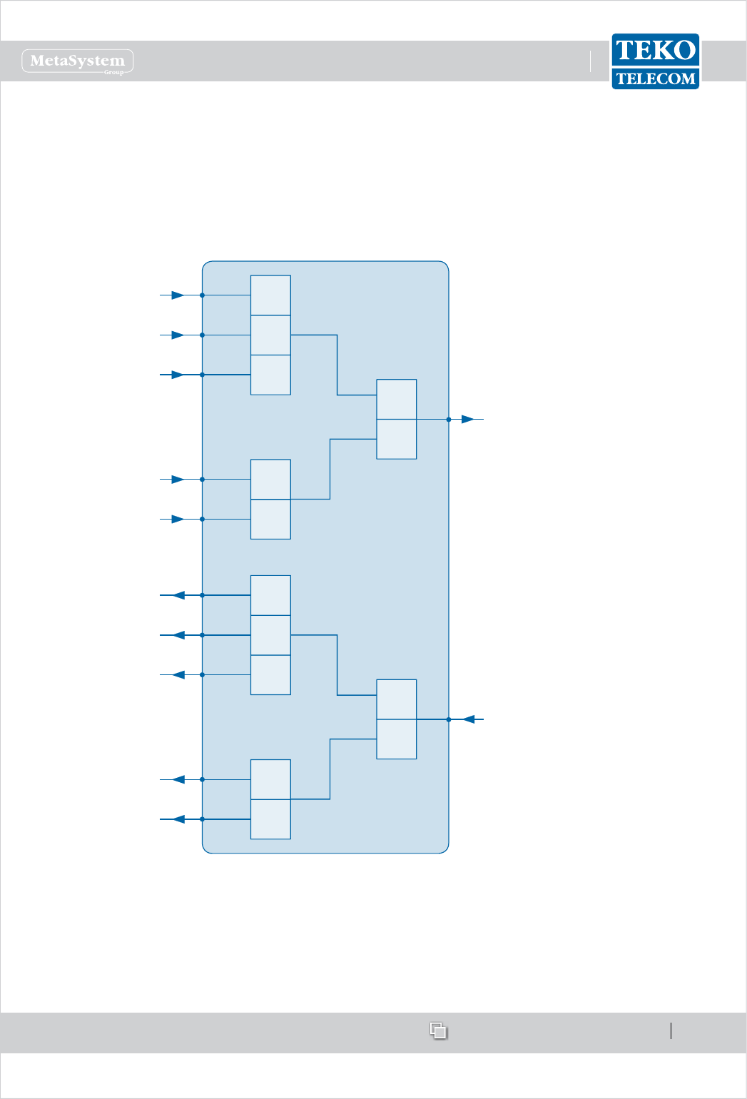
Example: EGSM, DCS, UMTS Triplexer block diagram - Downlink path
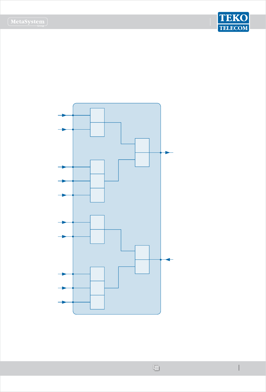
Example: Low band, PCS, AWS Triplexer block diagram - Uplink path
DL
DCS or
PCS
UMTS
or AWS
HIGH
LOWDL
(to built-in 4-way
splitter combiner)
BAND 1
(SMR, EGSM
or AMPS)
BAND 2
(DCS or PCS)
BAND 3
(UMTS or AWS)
ATT.
DCS or
AWS
UMTS
or PCS
HIGH
LOW
BAND 1
(SMR, EGSM
or AMPS)
BAND 2
(DCS or PCS )
BAND 3
(UMTS or AWS)
UL
(from built-in 4-way
splitter combiner)
ATT.
PCS
AWS
www.tekotelecom.it
www.tekotelecom.it
SIRIUS: Teko Telecom Modular Coverage and Capacity System
Let us repeat !
Doc ID Number 91 080 0781 - Rel. 04 page 34
english
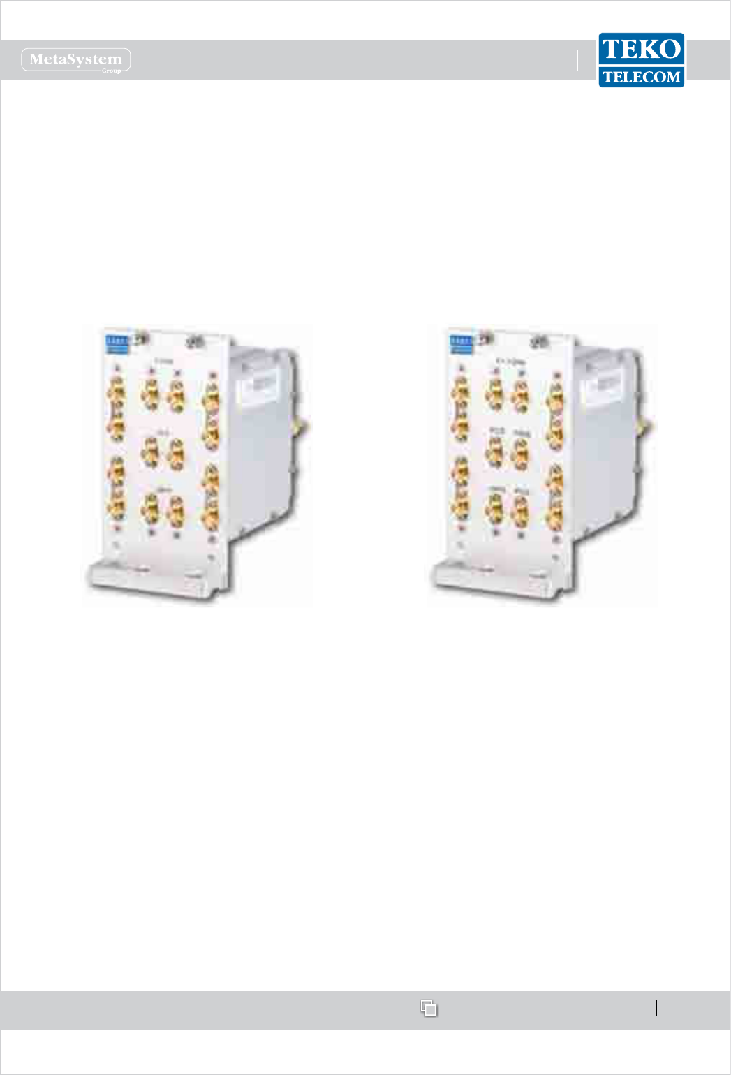
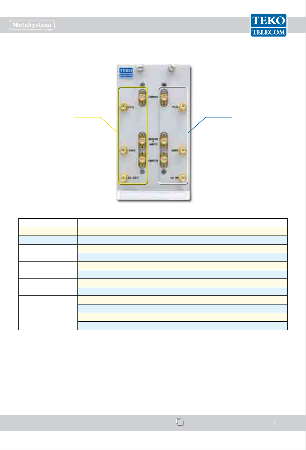
Triplexer Module Access Points -Example
Example: EGSM, DCS, UMTS Triplexer
with built-in 4-way Combiner/Splitter
Example: AMPS, PCS, AWS Triplexer
with built-in 4-way Combiner/Splitter
Connectors Description
EU Bands US Bands
EGSM f<1GHz Low band (700 to 960MHz) input (down-link path)
Low band (700 to 960MHz) output (up-link path)
DCS PCS DCS or PCS input (down-link path)
AWS DCS or AWS output (up-link path)
UMTS AWS UMTS or AWS input (down-link path)
PCS UMTS or PCS output (up-link path)
UL
WHEN USED TO MANAGE
MULTIPLE FIBER OPTIC
MODULES
Up-link path input
connectors (from
optical subrack)
WHEN USED TO MANAGE
MULTIPLE FOUR-WAY
COMBINER/SPLITTER MODULES
Up-link path output
connectors (to 4-way
combiner/splitter
modules)
DL
Down-link path
output connectors
(to optical subrack)
Down-link path input
connectors (from
4-way combiner/
splitter modules)
www.tekotelecom.it
www.tekotelecom.it
SIRIUS: Teko Telecom Modular Coverage and Capacity System
Let us repeat !
Doc ID Number 91 080 0781 - Rel. 04 page 35
english
Esaplexer (US bands)•
The Esaplexer is used in multi-band congurations to distribute signals operating over up to
6 dierent bands.
The Esaplexer can be connected to a 4-way splitter/combiner in order to manage up to 4 Fiber
Optic Transmitter/Receiver Modules (i.e. up to 16 Remote Units).
Esaplexer block diagram
SMR900
SMR700
DL OUT
SMR900
SMR900
AWSAWS
HI
SMR800C +
AMPS
SMR800C
+
AMPS
PCSPCS
LO
To a single optical module or
to the 4-way splitter-combiner
for the management of up to 4
optical modules
From the optical module or from
the 4-way splitter-combiner used
for the management of up to 4
optical modules
SMR900
SMR700
UL IN
SMR900
SMR900
AWSAWS
HI
SMR800C +
AMPS
SMR800C
+
AMPS
PCSPCS
LO
www.tekotelecom.it
www.tekotelecom.it
SIRIUS: Teko Telecom Modular Coverage and Capacity System
Let us repeat !
Doc ID Number 91 080 0781 - Rel. 04 page 36
english
Esaplexer Access Points•
DL path UL path
Label Description
DL OUT Down-link path output connector
UL IN Up-link path input connector
SMR700 SMR700 band input (down-link path)
SMR700 band output (up-link path)
SMR800C+AMPS SMR800C+AMPS bands input (down-link path)
SMR800C+AMPS bands output (up-link path)
SMR900 SMR900 band input (down-link path)
SMR900 band output (up-link path)
PCS PCS band input (down-link path)
PCS output (up-link path)
AWS AWS band input (down-link path)
AWS output (up-link path)
www.tekotelecom.it
www.tekotelecom.it
SIRIUS: Teko Telecom Modular Coverage and Capacity System
Let us repeat !
Doc ID Number 91 080 0781 - Rel. 04 page 37
english
Pentaplexer (EU bands)•
The Pentaplexer is used in multi-band congurations to distribute signals operating over up
to 5 dierent bands.
The Pentaplexer can be connected to a 4-way splitter/combiner in order to manage up to 4
Fiber Optic Transmitter/Receiver Modules (i.e. up to 16 Remote Units).
Pentaplexer block diagram
DL OUT
LTE800
DCS
LTE2600
HI
EGSM
UMTS
LO
To a single optical module or
to the 4-way splitter-combiner
for the management of up to 4
optical modules
From the optical module or from
the 4-way splitter-combiner used
for the management of up to 4
optical modules
UL IN
HI
LO
LTE800
EGSM900
DCS1800
UMTS2100
LTE2600
LTE800
DCS
LTE2600
EGSM
UMTS
LTE800
EGSM900
DCS1800
UMTS2100
LTE2600
www.tekotelecom.it
www.tekotelecom.it
SIRIUS: Teko Telecom Modular Coverage and Capacity System
Let us repeat !
Doc ID Number 91 080 0781 - Rel. 04 page 38
english
Pentaplexer Access Points•
DL path UL path
Label Description
DL OUT Down-link path output connector
UL IN Up-link path input connector
LTE800 LTE800 band input (down-link path)
LTE800 band output (up-link path)
EGSM900 EGSM900 band input (down-link path)
EGSM900 band output (up-link path)
DCS1800 DCS1800 band input (down-link path)
DCS1800 band output (up-link path)
UMTS2100 UMTS2100 band input (down-link path)
UMTS2100 output (up-link path)
LTE2600 LTE2600 band input (down-link path)
LTE2600 output (up-link path)
www.tekotelecom.it
www.tekotelecom.it
SIRIUS: Teko Telecom Modular Coverage and Capacity System
Let us repeat !
Doc ID Number 91 080 0781 - Rel. 04 page 39
english
Modules for the management of the System1.1.5
Supervision Module•
The Supervision Module (TSPV) allows the control and management of the entire Coverage
and Capacity System. The Supervision Module is provided with its own TCP/IP address and
with a built-in web server that allows control and management via a standard web browser.
The Coverage System can be accessed either via a physical (Ethernet LAN) connection or via
a modem connection.
Up to 9 Active Subracks can be monitored connecting a PC, either locally or remotely, to the
Ethernet port (LAN, RJ45 connector), available on the Supervision Module front panel.
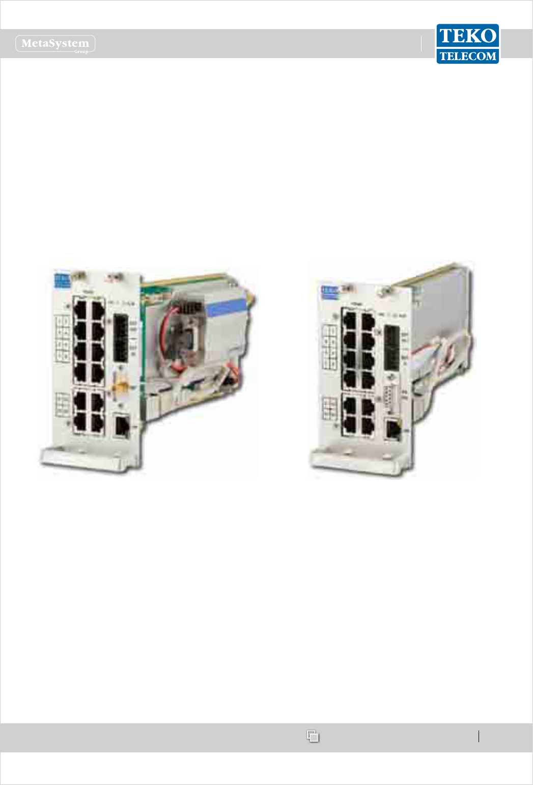
Supervision Module equipped with optional built-in
wireless modem
Supervision Module with RS232 port
For remote control the System can also be accessed via optional wireless modem (integrated
inside the supervision module).
When the optional built-in wireless modem is equipped an SMA input/output connector is
available on the Supervision front panel for remote management.
When the optional built-in wireless modem is not equipped, an RS232 port is available on the
Supervision front panel for connection to an external PSTN or wireless modem
A VPN application is installed on the Supervision Module to provide remote and secure access
to the System using the Internet.
www.tekotelecom.it
www.tekotelecom.it
SIRIUS: Teko Telecom Modular Coverage and Capacity System
Let us repeat !
Doc ID Number 91 080 0781 - Rel. 04 page 40
english
The Supervision Module can also act as an SNMP-agent providing integration into upper-
level management systems (NEM).
4 external alarms inputs and 4 dry contacts outputs are available on the Supervision module
front panel.
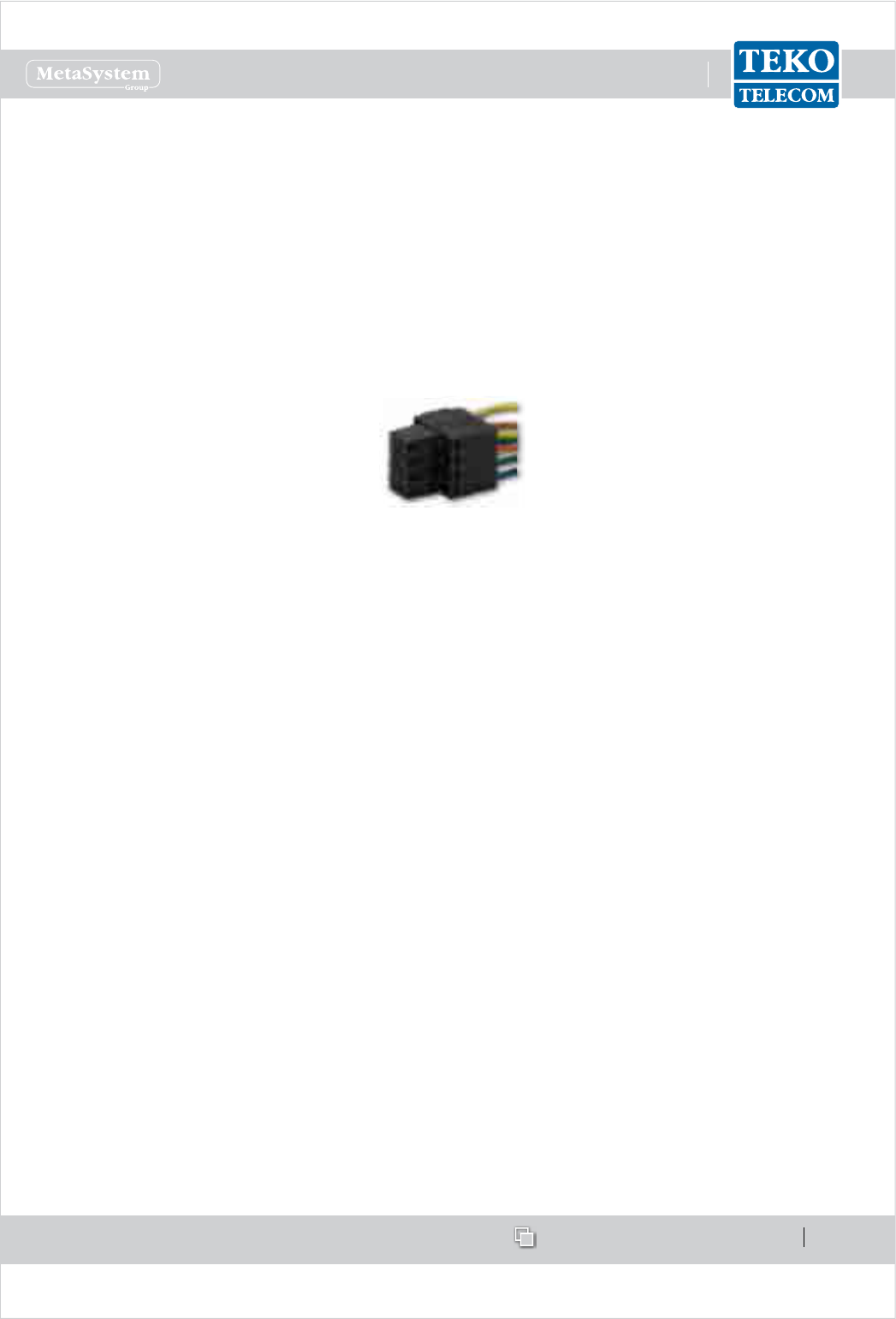
Please note
In order to more handily connect to EXT OUT / EXT IN dry contacts, 2x4-pole female connectors
are provided along with the Supervision Module.
2x4-pole female connector
Teko Telecom Operation and Maintenance Terminal (OMT) web pages allow the commissioning,
monitoring, setting and troubleshooting of the whole Coverage and Capacity System via a
user friendly graphical interface.
Teko Telecom OMC (Operation Management Centre) proprietary software is available to
control multiple Supervision Modules managing dierent Coverage and Capacity Systems in
a Network.
www.tekotelecom.it
www.tekotelecom.it
SIRIUS: Teko Telecom Modular Coverage and Capacity System
Let us repeat !
Doc ID Number 91 080 0781 - Rel. 04 page 41
english
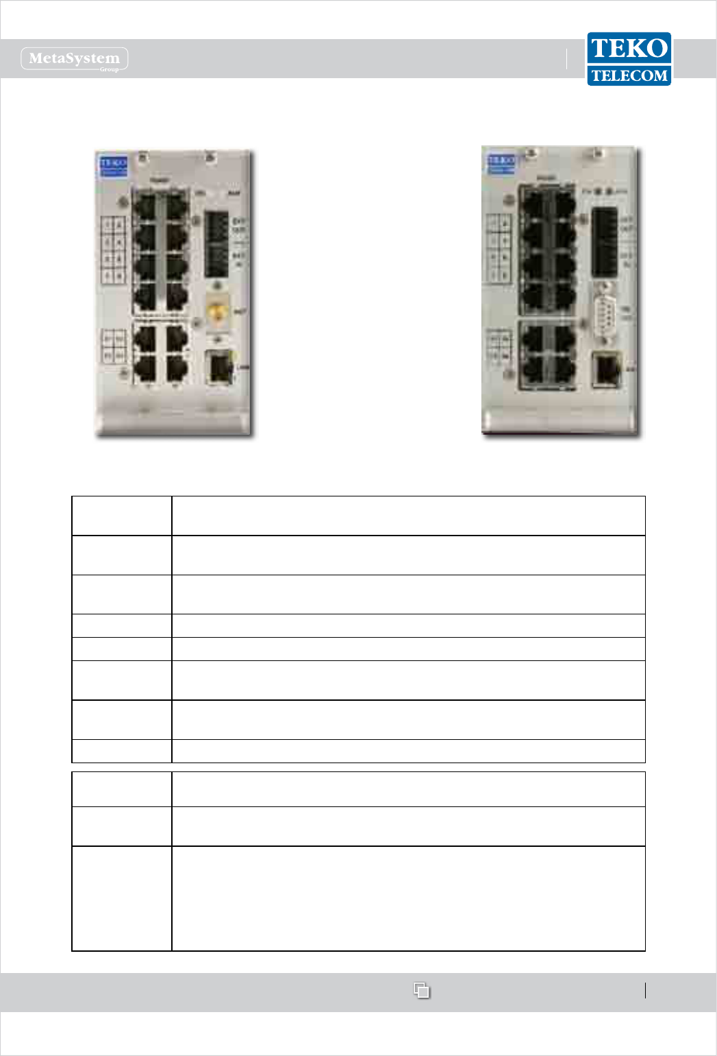
Supervision Module Access Points
Supervision Module equipped with
optional built-in wireless modem
Supervision Module with RS232
connector
Label
(Connectors)
Description
RS485
(1 to 8)
RJ45 connectors for monitored Optical Subracks management
RS485
(S1 to S4)
RJ45 connectors for remote Slave Supervision Modules
management
EXT OUT Dry contacts output connector
EXT IN External alarms input connector
RS232 9-pole D-Sub RS232 connector for connection to an external
modem
ANT Optional built-in modem input/output connector for remote
management
LAN RJ45 connector Local Control Interface
Label
(LEDs)
Description
ON Supervision Module operating status green LED:
ON when power supply is present
ALM
Supervision Module alarm status LED.
OFF: regular operation
Blinking Orange: presence of active alarms with warning severity level (4)
Orange: presence of active alarms with minor severity level (3)
Blinking Red: presence of active alarms with major severity level (2)
Red: presence of active alarms with critical severity level (1)
www.tekotelecom.it
www.tekotelecom.it
SIRIUS: Teko Telecom Modular Coverage and Capacity System
Let us repeat !
Doc ID Number 91 080 0781 - Rel. 04 page 42
english
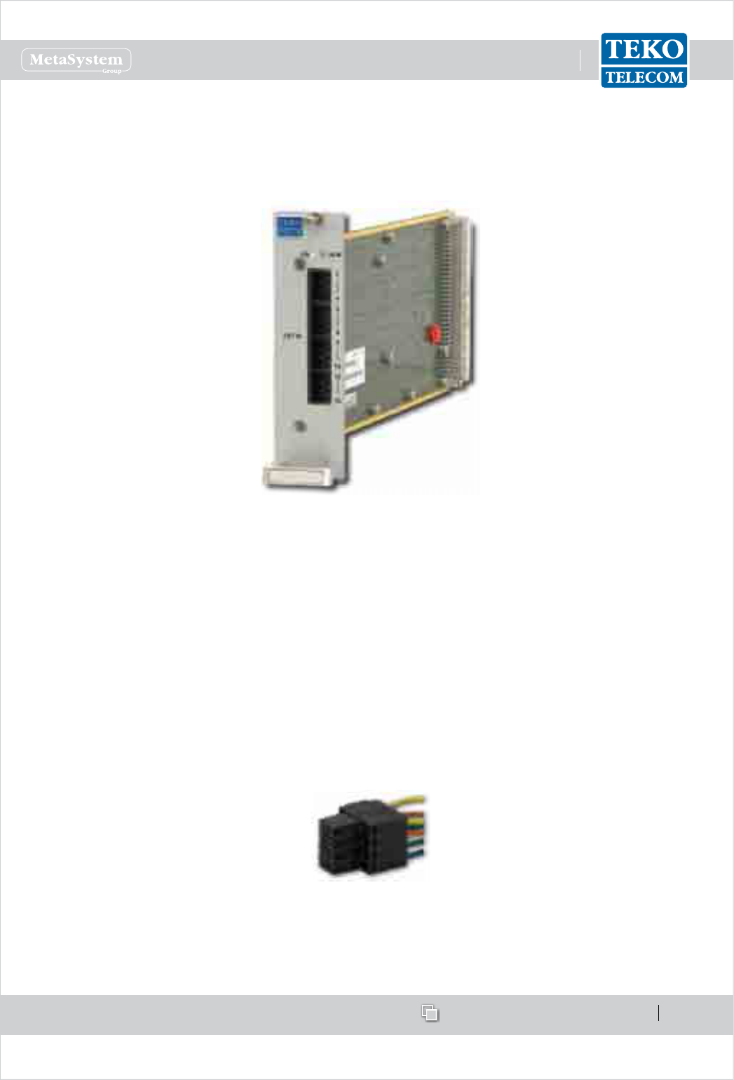
Alarm Board•
The Alarm Board is an optional I/O Module that can be equipped in addition to the Supervision
Module, in order to increase the number of supported external alarms.
Alarm Board equipped with 16 input pins - TEA-I16
The Alarm Board allows to manage up to 16 external alarms inputs: 16 external alarms input
connectors are available on the module front panel.
The 16 Input lines are opto-isolated and are activated by a short circuit between input pins
(max current ow during short = 6mA; max Vdc at input pins = 3,3V).
On request inputs 1-to-4 can be switched to dry output contacts, normally open or closed,
depending on HW conguration.
In order to more handily connect to the dry contacts input/output connectors, four 2x4-pole
female connectors are provided along with the Alarm Board Module.
2x4-pole female connector
www.tekotelecom.it
www.tekotelecom.it
SIRIUS: Teko Telecom Modular Coverage and Capacity System
Let us repeat !
Doc ID Number 91 080 0781 - Rel. 04 page 43
english
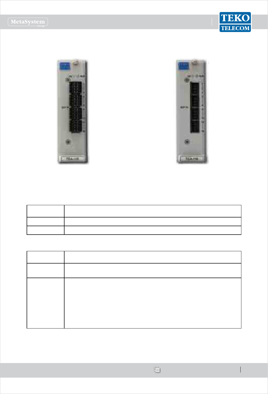
Alarm Board Access Points
Alarm Board
with female dry connectors
Alarm Board
without female dry connectors
Label
(Connectors)
Description
EXT IN External alarms input connector
EXT OUT Optional external alarms output connector (TEA-I12O4)
Label
(LEDs)
Description
ON Alarm Board Module operating status green LED:
ON when power supply is present
ALM
Alarm Board Module alarm status LED.
OFF: regular operation
Blinking Orange: presence of active alarms with warning severity
level (4)
Orange: presence of active alarms with minor severity level (3)
Blinking Red: presence of active alarms with major severity level (2)
Red: presence of active alarms with critical severity level (1)
www.tekotelecom.it
www.tekotelecom.it
SIRIUS: Teko Telecom Modular Coverage and Capacity System
Let us repeat !
Doc ID Number 91 080 0781 - Rel. 04 page 44
english
Power Supply Modules1.1.6
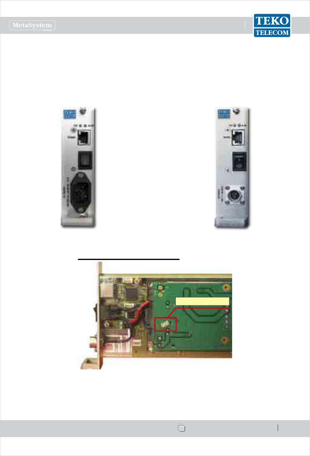
Power Supply Module•
Power Supply modules are used to supply Active Subracks.
Active Subracks can be AC powered (Universal mains, 85÷264Vac, 50-60Hz) or DC powered
(-72 ÷ -36Vdc): they can be equipped with either AC or DC Power Supply modules.
AC Power Supply Module DC Power Supply Module
The following gure shows the DC/DC Power Supply Module protection fuse position and
electrical rating. If the fuse blows, it has to be replaced.
If the fuse blows, it has to be replaced.
Fuse SMD T 125V-4A
Power Supply modules can be equipped in monitored Active Subracks, in the Master Active
Subrack or in a dedicated Active Subrack.
When Power Supply modules are equipped in monitored Active Subracks, the RJ45 connector
www.tekotelecom.it
www.tekotelecom.it
SIRIUS: Teko Telecom Modular Coverage and Capacity System
Let us repeat !
Doc ID Number 91 080 0781 - Rel. 04 page 45
english
available on the Power Supply Module front panel can be used for connection to the
Supervision Module, equipped in the Master Active Subrack.
Hot-plug 1+1 Redundancy feature is supported: it can be implemented to achieve high
system reliability.
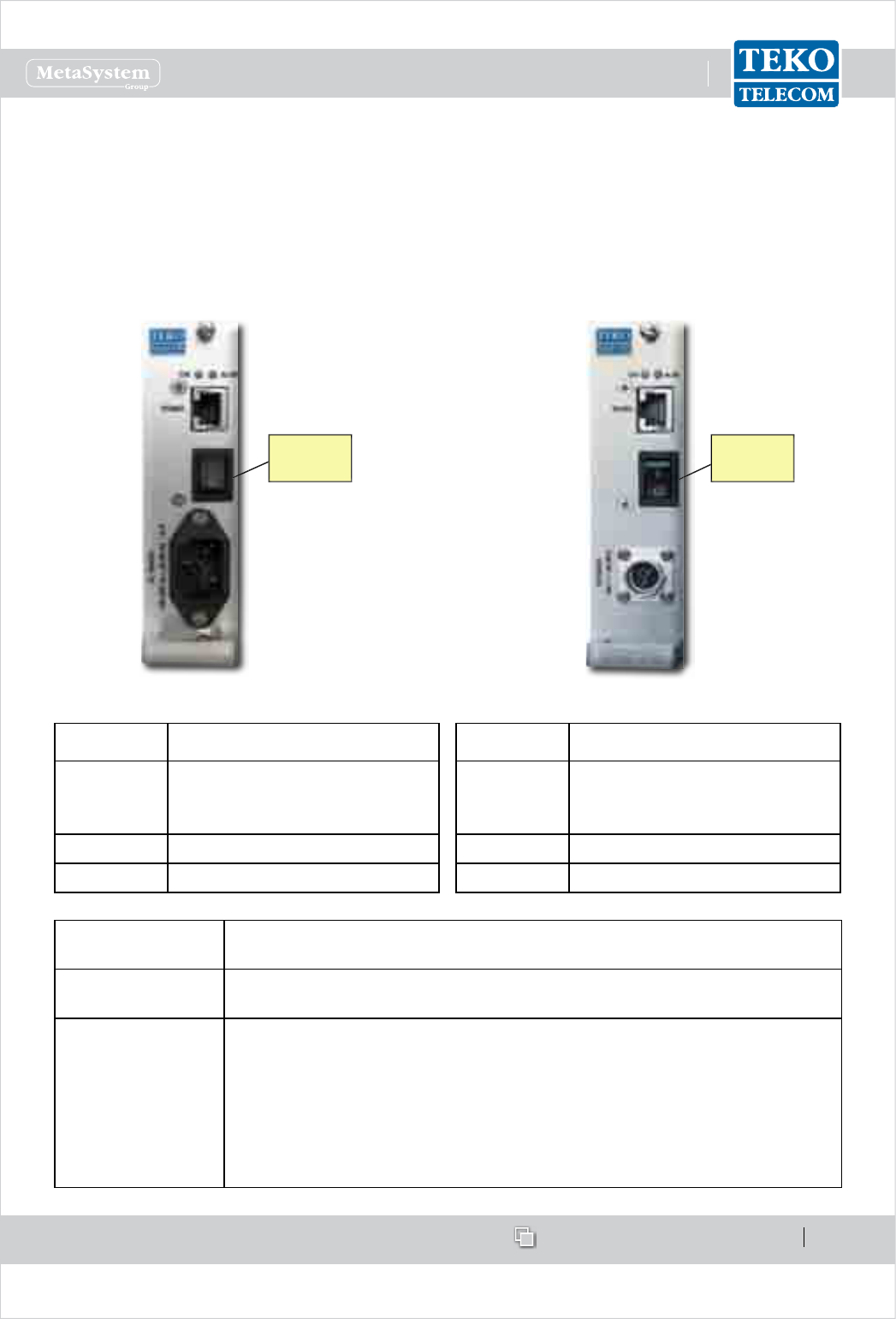
Power Supply Module Access Points
AC Power Supply Module DC Power Supply Module
DC switch
AC MAINS
switch
Connectors Description
RS485
RJ45 connector for RS485
connection to the Supervision
Module (monitored Subracks)
AC switch AC MAINS switch
AC MAINS AC MAINS socket (100-240Vac)
Connectors Description
RS485
RJ45 connector for RS485
connection to the Supervision
Module (monitored Subracks)
DC switch 48Vdc switch
DC MAINS Vdc input connector (48Vdc)
Label
(LEDs)
Description
POWER ON Power Supply Module operating status green LED:
ON when power supply is present
ALM
Power Supply Module alarm status LED.
OFF: regular operation
Blinking Orange: presence of active alarms with warning severity level
(4)
Orange: presence of active alarms with minor severity level (3)
Blinking Red: presence of active alarms with major severity level (2)
Red: presence of active alarms with critical severity level (1)
www.tekotelecom.it
www.tekotelecom.it
SIRIUS: Teko Telecom Modular Coverage and Capacity System
Let us repeat !
Doc ID Number 91 080 0781 - Rel. 04 page 46
english
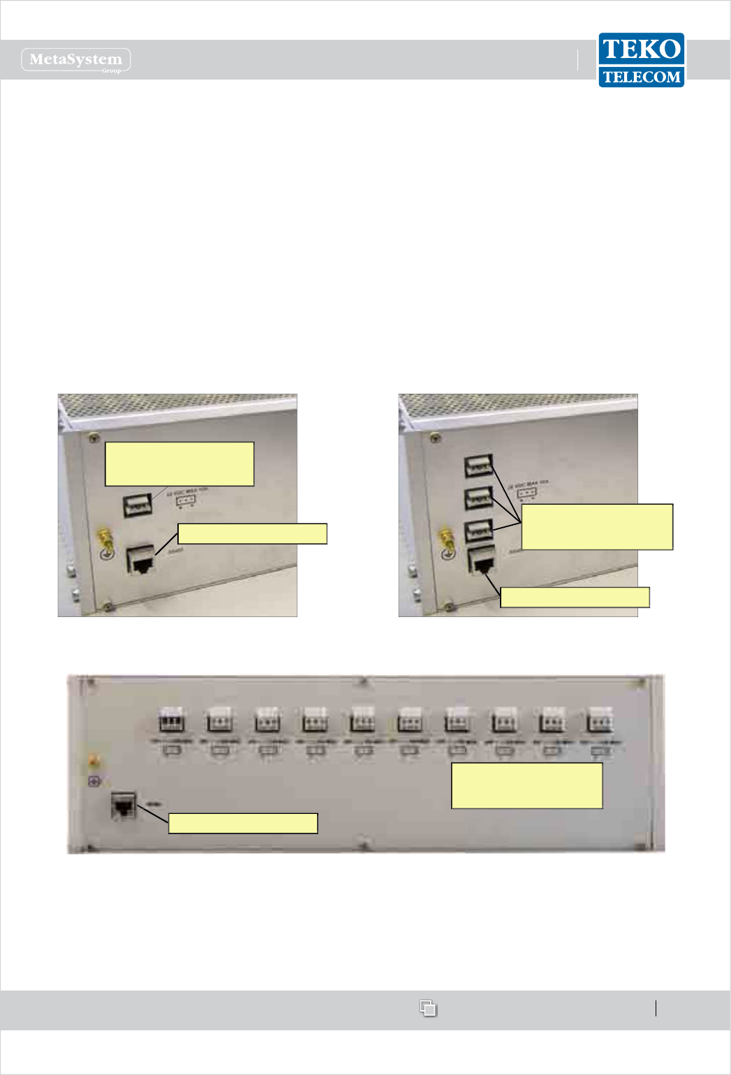
Subracks hosting the System modules1.1.7
Active subracks•
Active Subracks are provided with a backplane that allows the management and power
supply of up to 12 active modules and/or Power Supply modules.
Active subracks can be equipped with either AC or DC Power Supply modules.
The following connectors are available on each active subrack rear panel:
one or more 28Vdc input/output connectors.•
An RJ45 connector (RS485) to be used when power supply modules are not equipped •
in monitored Active Subracks. It allows connection of monitored Active Subracks to the
Supervision Module.
A ground bolt.•
28VDC ± 0.5VDC
input/output (max 10A)
RJ45 connector (RS 485)
Active Subrack with one 28Vdc
input/output connector
28VDC ± 0.5VDC
outputs (max 10A each)
RJ45 connector (RS 485)
Active Subrack with three 28Vdc
input/output connectors
28VDC ± 0.5VDC
outputs (max 10A each)
RJ45 connector (RS 485)
Active Subrack provided with ten 28Vdc input/output connectors
Passive subracks•
Passive modules that do not require power nor management to function can be housed in
Passive subracks thus allowing a reduction in the cost of the whole system.
www.tekotelecom.it
www.tekotelecom.it
SIRIUS: Teko Telecom Modular Coverage and Capacity System
Let us repeat !
Doc ID Number 91 080 0781 - Rel. 04 page 47
english
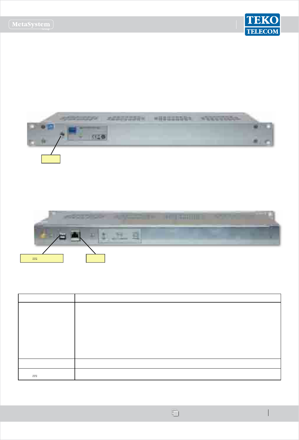
Forced-air cooling Subrack1.1.8
Teko Telecom forced-air cooling subrack is able to provide a maximum air ow of 180cfm (5m3/
min) in order to ensure the proper operation of cabinet installed equipment.
Forced-air cooling Subrack Access Points
Forced-air cooling subrack - Front view
Forced-air cooling subrack - Rear view
28V ;10A MAX RS485
LED
Access Point Description
LED
Forced-air cooling subrack general operating status LED
Green: normal operation
Blinking Orange: presence of active alarms with warning severity
level (4)
Orange: presence of active alarms with minor severity level (3)
Blinking Red: presence of active alarms with major severity level (2)
Red: presence of active alarms with critical severity level (1)
RS485 RJ45 connector for RS485 connection to the Supervision Module
28V ;10A MAX 28VDC ± 0.5VDC input (max 10A)
www.tekotelecom.it
www.tekotelecom.it
SIRIUS: Teko Telecom Modular Coverage and Capacity System
Let us repeat !
Doc ID Number 91 080 0781 - Rel. 04 page 48
english
Coverage and Capacity Solutions1.2
The components of SIRIUS, Teko Telecom Modular Coverage and Capacity System, can be
assembled to provide Modular Repeaters, Optical Systems and integrated solutions to improve
coverage in dierent environments.
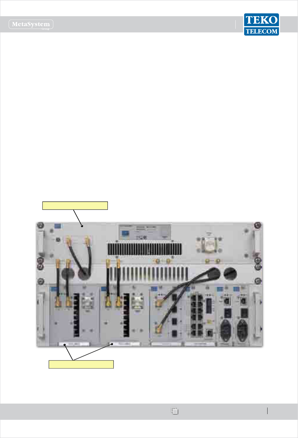
Modular O-air Repeaters - General description1.2.1
Teko Telecom multi-band multi-operator O-air Modular Repeaters represent the ideal
solution for cellular coverage extension, oering a cost eective alternative to dedicated BTSs
or Node Bs. They operate over dierent frequencies and with various frequency combinations
in the 380 to 2700MHz frequency range.
No physical connections are required between the Modular Repeaters and the cellular
network: the Digital Donor Front End Module is connected to a Donor Antenna, providing
the connection towards a BTS or Node B over an air link.
Teko Telecom Modular O-air Repeaters can be set up by proper combination of Digital Donor
Front End Modules and Service Front End Subracks.
Donor Front End Modules
Service Front End Subrack
The Digital Donor Front End is the single-band/single-operator RF interface towards the
signal source; the Service Front End is the multi-band/single operator equipment that
www.tekotelecom.it
www.tekotelecom.it
SIRIUS: Teko Telecom Modular Coverage and Capacity System
Let us repeat !
Doc ID Number 91 080 0781 - Rel. 04 page 49
english
provides wireless signal to the area to be covered.
O-air Modular Repeaters can be equipped with one Donor Front End or more Donor Front
End modules to make multiple congurations available: single operator (single band / multi-
band) and multi-operator (single-band / multi-band).
A single-band single-operator Repeater can be set-up combining a Digital Donor Front End
Module and a Service Front End Subrack.
Up to 4 Digital Donor Front End Modules can be connected to a single Service Front End
obtaining a single-band 4-operator O-air Repeater.
Digital Donor Front End Modules can be connected to dierent Service Front End Subracks to
provide multi-band/multi-operator Systems.
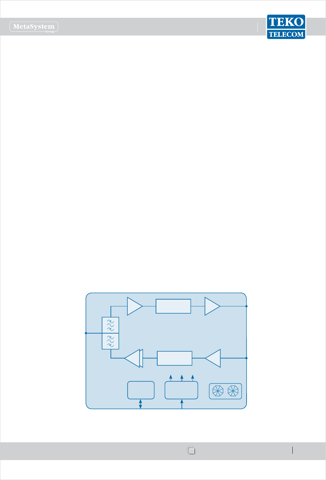
Operating principle
Modular repeaters use a directional antenna to interface with the operator’s donor BTS (or
Node B) and one or more service antennas to transmit the amplied wireless signals to the
area to be covered.
In down-link the repeater receives the signals from the BTS (or Node B), amplies them and
re-transmits them to the mobiles. In the up-link path the repeater receives the signals from
the mobiles (MS), amplies them and re- transmits them to the base station.
Each DFE module hosts the duplexer, to be connected to the Donor Antenna to separate/
combine Downlink and Uplink paths.
DL RF
Out
UL RF
In
Donor
Antenna
Port
Duplexer
P DC/DC
+12V +1.8V+3.3V
28÷30VDC
RS485
FANS
Digital Filter
Digital Filter
PA
LNA
In downlink the signal from the Donor antenna is preamplied by a Low Noise Amplier and
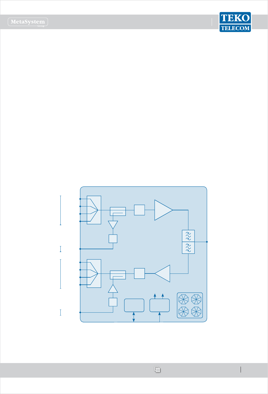
www.tekotelecom.it
www.tekotelecom.it
SIRIUS: Teko Telecom Modular Coverage and Capacity System
Let us repeat !
Doc ID Number 91 080 0781 - Rel. 04 page 50
english
converted into an IF signal by a down converter. The selection of the band of frequencies or
channels to be extended is handled by a digital lter.
The digital ltering can manage 1 variable band or 2 variable sub-bands.
An up converter converts the IF signal into an RF signal.
In uplink the signal from the Service Front End Subrack is converted into an IF signal by a
down converter, ltered and re-converted into an RF signal, amplied by a power amplier
and re-transmitted to the signal source.
Each TSFE subrack hosts the duplexer, to be connected to a Service antenna to separate/
combine Downlink and Uplink paths.
In Downlink the signals from the Donor Front-End Modules are combined, amplied (High
Power Amplier) and then transmitted to the area to be covered by the Service Front End
Subrack.
In Uplink, the RF signal from the Service antenna is amplied by a Low Noise Amplier (LNA)
and split to feed up to 4 Donor Front-End Modules.
PA
DL in1
Service
Antenna Port
Duplexer
P DC/DC
+3.3V +5V
28÷30VDCRS485
Digital
Attenuator
DL in2
DL in3
DL in4
DL out
LNA
UL out1 Digital
Attenuator
UL out2
UL out3
UL out4
UL in
Digital
Attenuator
Digital
Attenuator
4:1
4:1
FANS
From DFEs
To DFEs
To Optics
From Optics
When Modular Repeaters do not provide satisfactory coverage (extensive areas, long tunnels),
they can be used along with a ber fed System (Teko Telecom Optical System).
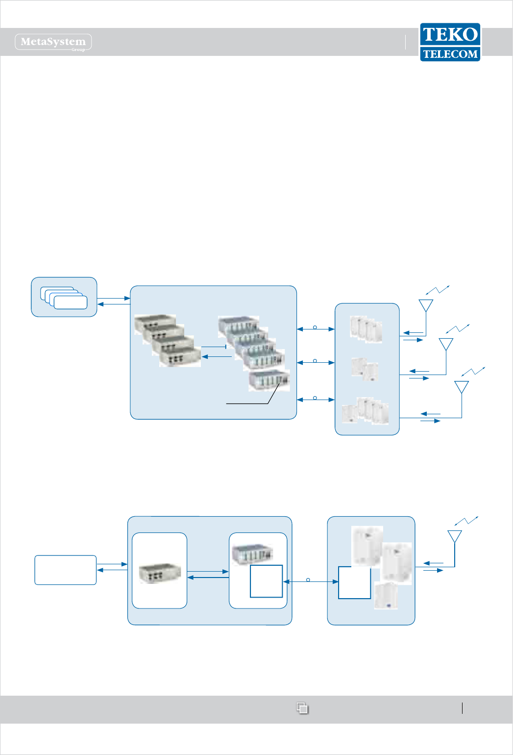
www.tekotelecom.it
www.tekotelecom.it
SIRIUS: Teko Telecom Modular Coverage and Capacity System
Let us repeat !
Doc ID Number 91 080 0781 - Rel. 04 page 51
english
Optical Systems - General Description1.2.2
Teko Telecom Coverage and Capacity System components can be congured to provide a
modular multi-band multi-operator Optical System.
Optical Systems are based on the Radio over Fibre technology, which enables radio signals
transmission over optical bres. This technology oers wide bandwidth and very little loss
along the ber optic bre, allowing the signals to be propagated over long distances. This
allows extensive areas coverage.
Each Teko Telecom Optical System is made up of two main parts: the Master Unit, interfacing
the signal source, and Remote Units, distributed throughout the territory to be served. Master
Unit and Remote Units are connected via single mode optical bres (SMR 9/125).
REMOTE UNITS
Passive POI Subracks
RF Interface
Optical Subracks
Optical Interface and Supervision
COAXIAL CABLE
(RF SIGNAL)
BTS, Node B or
Repeater
SIGNAL SOURCE
SINGLE MODE
OPTICAL FIBRE
(OPTICAL SIGNAL) COAXIAL CABLE
RF SIGNAL
COAXIAL CABLE
(RF SIGNAL)
COAXIAL CABLE
(RF SIGNAL)
RF SIGNAL
Supervision Module
MASTER UNIT
SINGLE MODE
OPTICAL FIBRE
(OPTICAL SIGNAL)
SINGLE MODE
OPTICAL FIBRE
(OPTICAL SIGNAL)
Master UnitA –
The Master Unit provides both the RF interface towards the signal source (one or more BTSs
or Node Bs) and the optical interface towards Remote Units.
One or more
BTSs, Node Bs or
Repeaters
RF SIGNAL
Fiber Optic
Receivers
Transmitters
REMOTE UNITS
RF Interface
POI Subrack
MASTER UNIT
Optical Subrack
RF SIGNAL
Fiber Optic
Receivers
Transmitters OPTICAL
SIGNALS
RF SIGNAL
It is a rack-based modular equipment: Teko Telecom Coverage and Capacity Systems
components can be assembled in a variety of ways providing dierent Master Unit conguration

www.tekotelecom.it
www.tekotelecom.it
SIRIUS: Teko Telecom Modular Coverage and Capacity System
Let us repeat !
Doc ID Number 91 080 0781 - Rel. 04 page 52
english
options.
Each Master Unit can be equipped with one or more RF interface subracks subracks hosting
RF interface modules) and with one or more Optical Subracks (Active Subracks hosting Fiber
Optic Transmitter/Receiver modules).
When the Master Unit is equipped with Master and Slave Point to Point Modules, RF interface
subracks and optical subracks can be separated by a maximum distance of 20km.
RF interface subracks•
RF Interface subracks operate over dierent frequencies and with various frequency
combinations in the frequency range from 380 to 2700MHz.
Each RF interface subrack can be equipped with one or more RF Interface modules. Each
module interfaces to a single mobile operator / mobile standard signal source, making
multiple congurations available: single operator (single band / multi-band) and multi-
operator (single-band / multi-band).
Master Unit RF Interface modules can be Point of Interface (POI/TAPOI) modules and/or Donor
Front End modules.
Point of Interface modules are connected to the signal source via coaxial cable: each module
is connected to a single operator/ single standard signal source (BTS or Node B). Master Units
equipped with POI/TAPOI modules must be installed next to the donor BTS or Node B.
POI modules can be equipped in passive subracks; TAPOI modules require active subracks
(SUB-TRX).
Donor Front End modules allow the Optical System to be driven without the need of a
dedicated BTS or Node B: each Donor Front End module interfaces with a Donor Antenna
oriented towards a BTS or NodeB (connection over an air link).
Donor Front End modules require an active subrack (SUB-TRX). Each subrack can be equipped
with up to 4 Donor Front End Modules.
RF Interface subracks also host passive modules providing distribution and ltering:
1:4 Splitter/Combiner•
Band Splitter/Combiner (Triplexer) with built-in 1:4 Splitter/Combiner•
Pentaplexer/Esaplexer.•
Due to the exible conguration options of Teko Telecom Coverage and Capacity Systems,
the same passive modules can be used for dierent purposes:
the 4-way splitter/combiner can be used to manage: multiple RF interface modules, •
operating in the same band (Multi-Operator Optical Systems) or multiple Fiber Optic
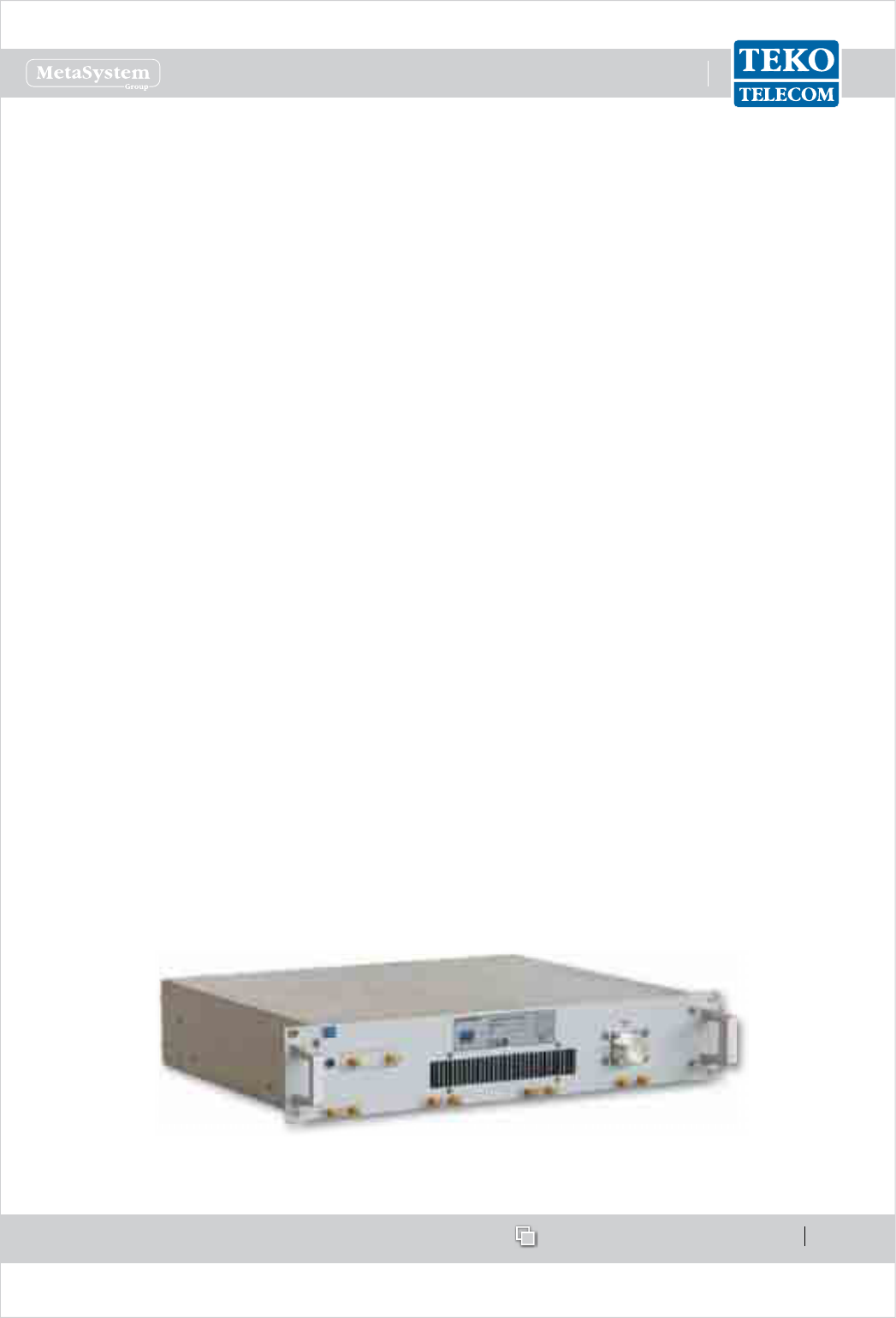
www.tekotelecom.it
www.tekotelecom.it
SIRIUS: Teko Telecom Modular Coverage and Capacity System
Let us repeat !
Doc ID Number 91 080 0781 - Rel. 04 page 53
english
modules;
the triplexer can be used to manage•
up to 3 RF interface modules operating in dierent bands and up to 4 Fiber Optic -
Transmitter/Receiver Modules or
up to 3 Service Front End subracks operating in dierent bands and up to 4 Fiber Optic -
Transmitter/Receiver Modules or
up to 3 four-way splitter/combiner modules - used to manage multiple RF interface -
modules (up to 4 for each band) - and up to 4 Fiber Optic Transmitter/Receiver
Modules.
the Pentaplexer and Esaplexer can be used to manage•
up to 5 (Pentaplexer)/ up to 6 (Esaplexer) RF interface modules operating in dierent -
bands or
up to 5 (Pentaplexer)/ up to 6 (Esaplexer) Service Front End subracks operating in -
dierent bands or
up to 5 (Pentaplexer)/ up to 6 (Esaplexer) four-way splitter/combiner modules- used -
to manage multiple RF interface modules (up to 4 for each band).
The RF Interface subracks can also be equipped with up to 4 Master Point to Point modules for
the management of up to 4 optical subracks installed in dierent remote locations.
Digital Donor Front End modules can be connected to Service Front End Subracks to provide
coverage to the area adjoining the Master Unit site.
Each Service Front End can be fed by up to 4 Donor Front-End Modules interfacing the
signal source. Downlink and uplink auxiliary ports are available to drive the Optical
System.
Service Front End Subrack
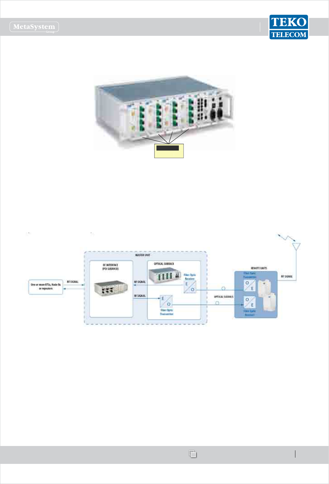
www.tekotelecom.it
www.tekotelecom.it
SIRIUS: Teko Telecom Modular Coverage and Capacity System
Let us repeat !
Doc ID Number 91 080 0781 - Rel. 04 page 54
english
Optical Subracks•
Optical Subracks are Active Subracks hosting Fiber Optic Transmitter/Receiver modules.
Fiber Optic
Modules
Fiber Optic Transmitter/Receiver modules are the optical interface towards Remote Units:
they provide RF to optical /optical to RF conversion.
Fiber Optic modules are connected to Remote Units via single-mode optical ber (SMR
9/125); each Fiber Optic Module can manage up to 4 Remote Units (up to 5 in cascade
conguration).
Up to 6 Fiber Optic Modules can be housed in a single Optical Subrack.
In Downlink RF signals are converted into optical signals in the Fiber Optic Transmitter modules
of the Master Unit and then they are propagated through optical bre distribution to Remote
Units. In the Fiber Optic Receiver of each Remote Unit, the optical signal is then converted
back into an RF signal that is amplied and transmitted to mobiles through an antenna or a
passive distribution system.
In Uplink RF signal is converted into an optical signal in the Fiber Optic Transmitter of each
Remote Unit and then it is propagated via bre optics to the Master Unit. Optical signals from
Remote Units are then converted by the Fiber Optic Receiver modules of the Master Unit into
RF signals and transmitted to the signal recipient.
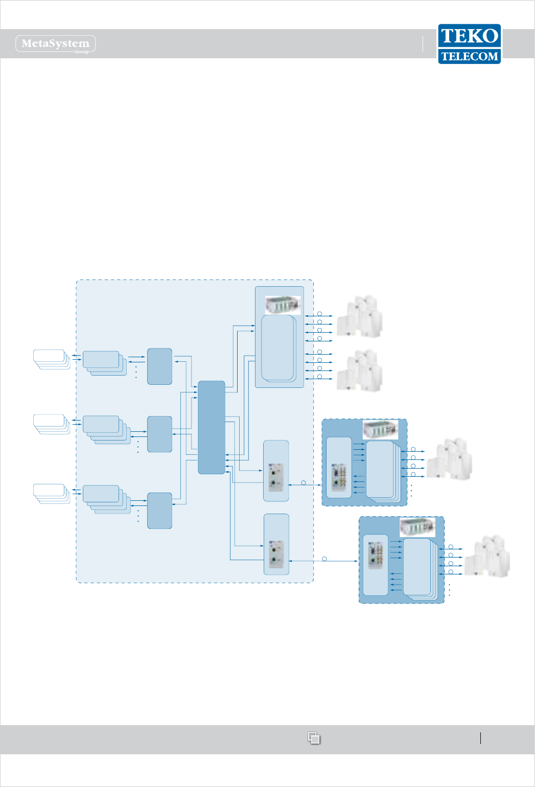
www.tekotelecom.it
www.tekotelecom.it
SIRIUS: Teko Telecom Modular Coverage and Capacity System
Let us repeat !
Doc ID Number 91 080 0781 - Rel. 04 page 55
english
Uplink and downlink optical signals are transmitted over the same single mode optical bre
(Wavelength Division Multiplexing -WDM- technology).
The Master Optical Subrack also hosts the Supervision Module for the management of the
whole System.
When the Coverage System includes point to point links, each remote optical subrack hosts
the Slave point to point module to be connected, via optical bre, to its Master Point to Point
module, equipped in the RF interface subracks.
The slave point to point module includes the 4-way splitter/combiner to manage up to 4 Fiber
Optic Transmitter/Receiver Modules and a built-in Supervision unit for the management of
the remote subrack and connected Remote Units.
4-WAY
SPLITTER
COMBINER
TRIPLEXER
+
4-WAY
SPLITTER
COMBINER
FIBER OPTIC
TRANSMITTER
RECEIVER
MODULES
4-WAY
SPLITTER
COMBINER
4-WAY
SPLITTER
COMBINER
TO/FROM
REMOTE UNITS
SIGNAL SOURCE
SIGNAL SOURCE
SIGNAL SOURCE
INTERFACE MODULES
OPERATING IN THE
SAME BAND
INTERFACE MODULE:
POI MODULE or
TDFE MODULE
INTERFACE MODULES
OPERATING IN THE
SAME BAND
INTERFACE MODULE:
POI MODULE or
TDFE MODULE
INTERFACE MODULES
OPERATING IN THE
SAME BAND
INTERFACE MODULE:
POI MODULE or
TDFE MODULE
MASTER
POINT TO POINT
MODULE
SLAVE
POINT TO POINT
MODULE
POINT TO
POINT
OPTICAL LINK
POINT TO
POINT
OPTICAL LINK
MASTER
POINT TO POINT
MODULE
REMOTE OPTICAL
SUBRACK 1
FIBER OPTIC
TRANSMITTER
RECEIVER
MODULES
TO/FROM
REMOTE UNITS
FIBER OPTIC
TRANSMITTER
RECEIVER
MODULES
TO/FROM
REMOTE UNITS
SLAVE
POINT TO POINT
MODULE
REMOTE OPTICAL
SUBRACK 2
OPTICAL SUBRACK
MULTI-OPERATOR MULTI-STANDARD RF INTERFACE
EQUIPPED WITH MASTER POINT TO POINT MODULES
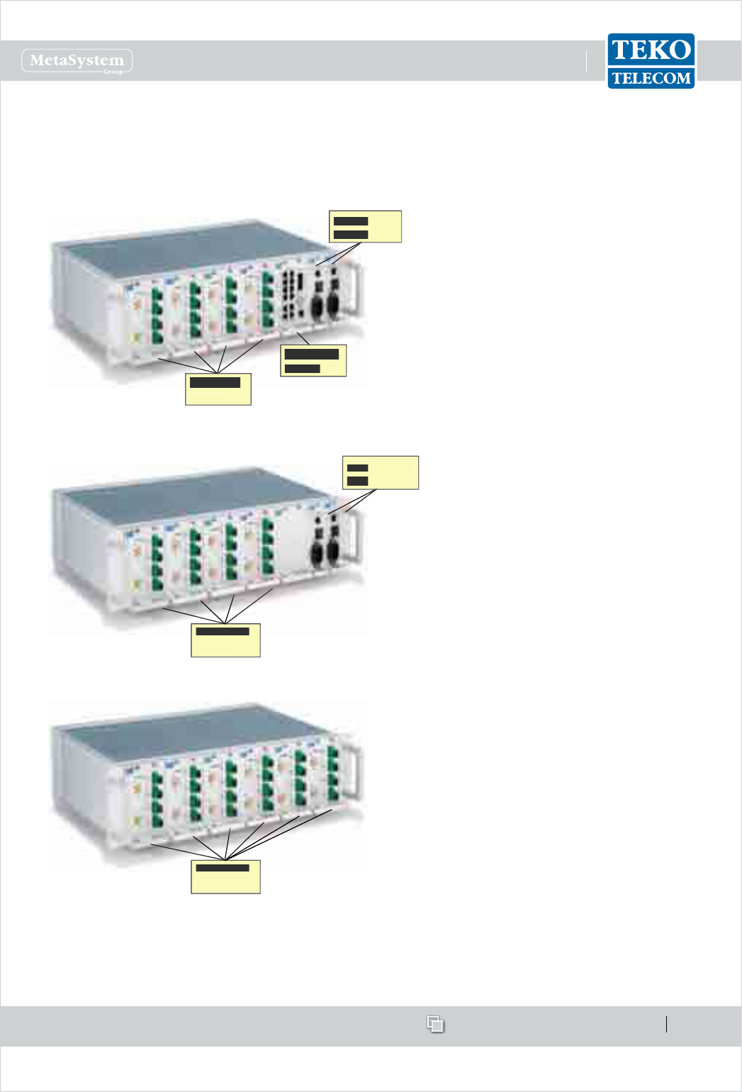
www.tekotelecom.it
www.tekotelecom.it
SIRIUS: Teko Telecom Modular Coverage and Capacity System
Let us repeat !
Doc ID Number 91 080 0781 - Rel. 04 page 56
english
Optical Subracks can be AC or DC powered. Power Supply modules can be equipped
in monitored Optical Subracks or in the Master Optical Subrack or in dedicated Active
Subracks.
Example of Master Optical Subrack hosting
the Supervision module, 4 Fiber Optic
Transmitter/Receiver modules, and 2 Power
Supply Modules (the second Power Supply
Module, optional, provides power supply
redundancy for higher reliability)
Power Supply
Power Supply
Modules
Modules
Fiber Optic
Modules
Supervision
Module
Power Supply
Power Supply
Modules
Modules
Fiber Optic
Fiber Optic
Modules
Example of Monitored Optical Subrack
equipped with 4 Fiber Optic Transmitter/
Receiver Modules and 2 Power Supply
Modules
Fiber Optic
Fiber Optic
Modules
Example of Monitored Optical Subrack
equipped with 6 Fiber Optic Transmitter/
Receiver Modules
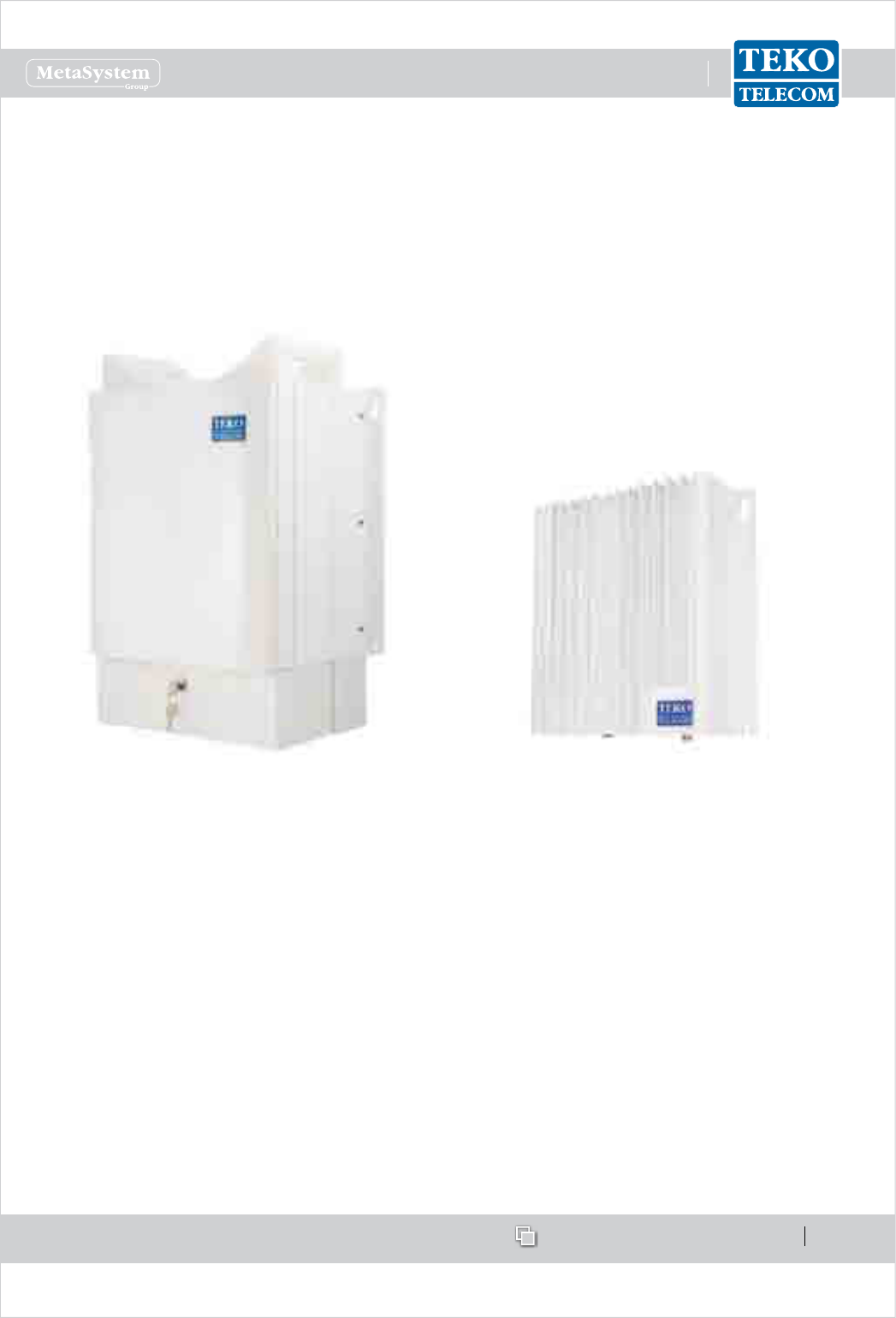
www.tekotelecom.it
www.tekotelecom.it
SIRIUS: Teko Telecom Modular Coverage and Capacity System
Let us repeat !
Doc ID Number 91 080 0781 - Rel. 04 page 57
english
Remote UnitsB –
Remote Units distribute wireless signals throughout the area to be covered ; they can be
installed up to 20km (12.4miles) from the Master Unit site.
Remote Units can be Single, Dual or Tri-band with dierent power classes: Very High, High,
Medium and Low.
Single, Dual or Tri-band Very High, High and
Medium Power Remote Unit
Single, Dual or Tri-band Low Power Remote
Unit
Remote Units are equipped with the Fiber Optic Receiver and Transmitter modules (for Optical
to RF and RF to Optical conversion) power ampliers and ltering.
A single Master Unit can drive up to 144 Remote Units. Various network structures can be
supported by the Master Unit: the Remote Units of the same Optical System can be deployed
with a point-to-point connection (star-conguration - using one ber optic per Remote
Unit) or with cascading of up to 5 Remote Units using a single bre and optimized optical
couplers.
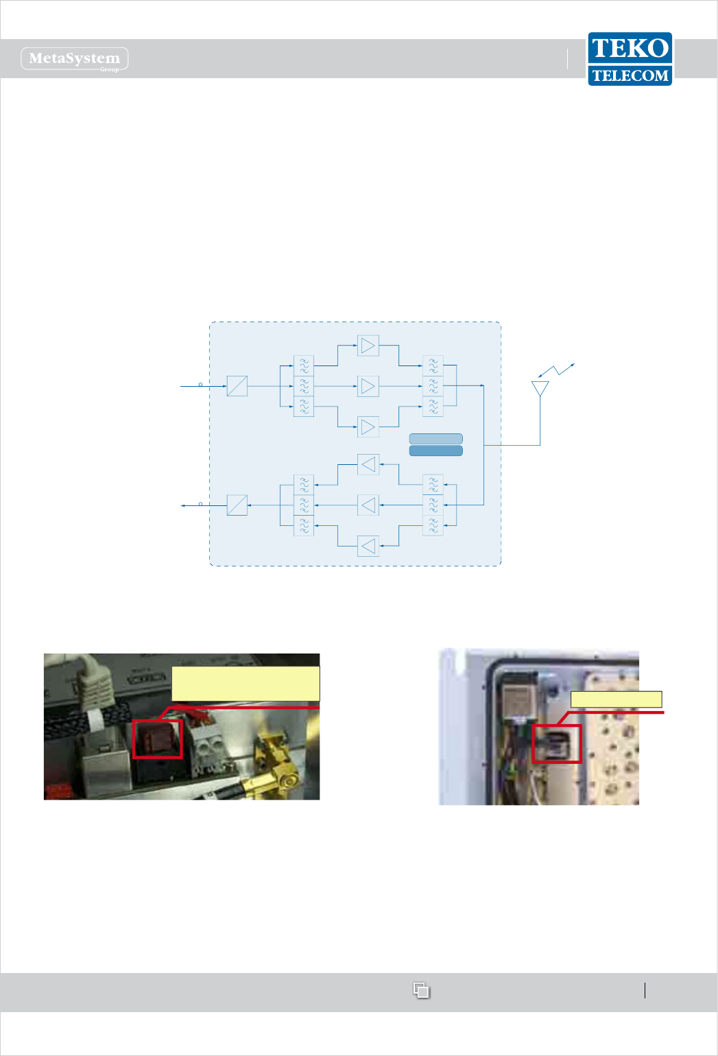
www.tekotelecom.it
www.tekotelecom.it
SIRIUS: Teko Telecom Modular Coverage and Capacity System
Let us repeat !
Doc ID Number 91 080 0781 - Rel. 04 page 58
english
The following gure shows the Tri-band Remote Unit block diagram: in down-link the optical
signal from Master Unit is converted into an RF signal by the Fiber Optic Receiver module.
RF signals, ltered by the triplexer, are amplied by Low, Medium, High or Very High Power
ampliers (Low, Medium, High or Very High Power Remote Units), ltered and transmitted
through an antenna or a passive distribution system.
In up-link the RF signal is ltered by the triplexer. The three RF signals are amplied by
Low-Noise Ampliers, ltered and then converted into an optical signal by the Fiber Optic
Transmitter module. The signal is transmitted via ber optics to the Master Unit.
Fiber Optic
Receiver
From MASTER unit
(DownLink)
To MASTER unit
(UpLink)
PA900
PA1800
PA2100
Antenna
System
LNA900
LNA1800
LNA2100
Fiber Optic
Transmitter
Management module
PSU
O
E
O
E
Example: Tri-band Remote Unit block diagram
Please Note: each nal power amplier is protected by a fuse.
Very High Power/High Power/Medium Power nal
ampliers fuse position and electrical rating
Fuse 32V-7,5A HPA/MPA
Fuse 32V-20A VHPA Fuse 32V-7,5A
Low Power nal amplier fuse position and
electrical rating
The management module collects information relevant to the various modules. An RF modem
allows data communication over ber between Remote Unit and Master Unit.
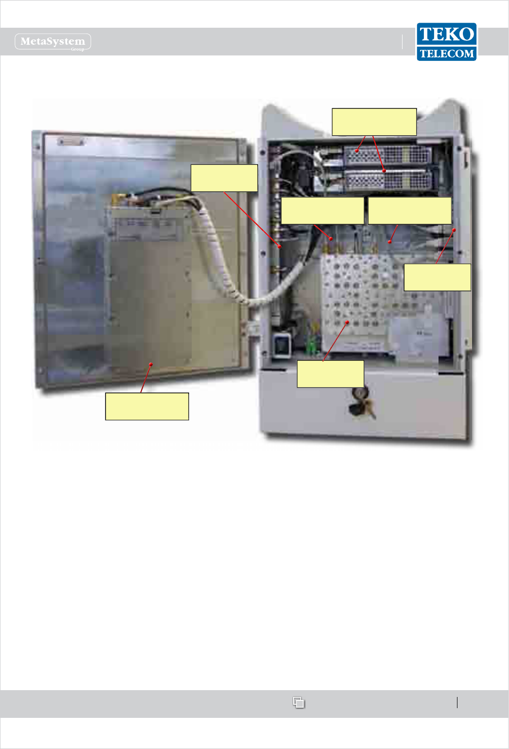
www.tekotelecom.it
www.tekotelecom.it
SIRIUS: Teko Telecom Modular Coverage and Capacity System
Let us repeat !
Doc ID Number 91 080 0781 - Rel. 04 page 59
english
High/Medium Power Remote Units Composition•
POWER SUPPLY
MODULES
SUPERVISION
MODULE
FIBER OPTIC
MODULE
CAVITY
6-PLEXER
POWER AMPLIFIER
(BAND1)
POWER AMPLIFIER
(BAND2)
POWER AMPLIFIER
(BAND3)
PLEASE NOTE:
The Very High/High/Medium Power Remote Unit case is equipped with a lock to guarantee
protection of the equipment. The following procedure describes how to open the
equipment.
OPENING THE REMOTE UNIT
Unlock the cables protection using the keys delivered with the equipment•
Remove the cables protection•
Remove the Remote Unit cover, sliding it downwards•
Unscrew the 6 screws on the Remote Unit door•
Open the Remote Unit door.•
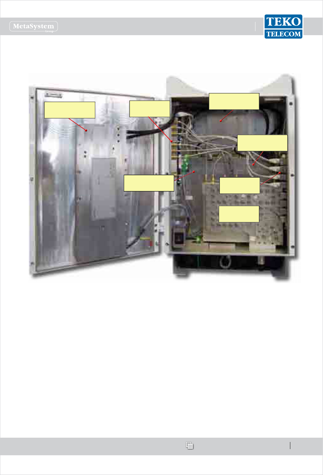
www.tekotelecom.it
www.tekotelecom.it
SIRIUS: Teko Telecom Modular Coverage and Capacity System
Let us repeat !
Doc ID Number 91 080 0781 - Rel. 04 page 60
english
Very High Power Remote Unit Composition
POWER SUPPLY
MODULE
CAVITY
6-PLEXER
SUPERVISION
MODULE
FIBER OPTIC
MODULE
POWER AMPLIFIER
(BAND1)
POWER AMPLIFIER
(BAND2)
POWER AMPLIFIER
(BAND3)
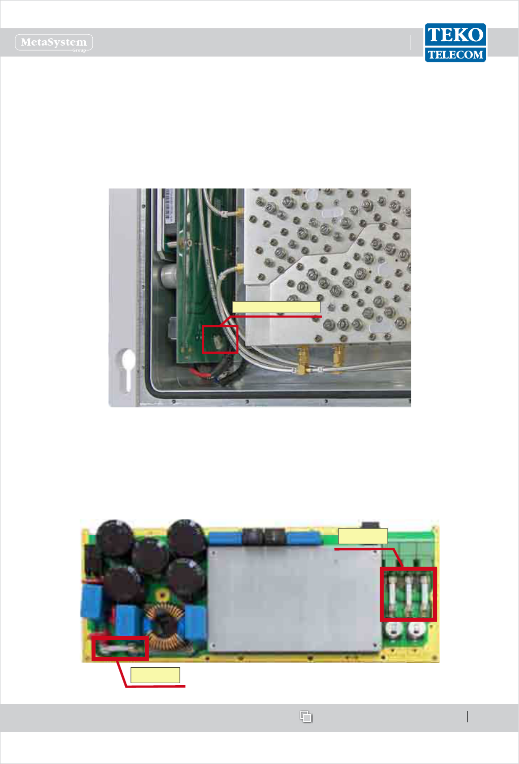
www.tekotelecom.it
www.tekotelecom.it
SIRIUS: Teko Telecom Modular Coverage and Capacity System
Let us repeat !
Doc ID Number 91 080 0781 - Rel. 04 page 61
english
Low Power Remote Units can be either AC powered (Universal mains, 85÷264Vac, 50-60Hz) or
DC powered (-72 ÷ -36Vdc).
The following gure shows the DC powered Low Power DC/DC Power Supply Module
protection fuse position and electrical rating.
Fuse SMD T 125V-4A
Very High/ High and Medium power Remote Units are AC powered (Universal mains,
85÷264Vac, 50-60Hz).
The Very High Power Remote Unit Power Supply module is protected by 4 fuses. The following
gure shows the protection fuses position and electrical ratings.
F20A, 250V
F25A, 250V
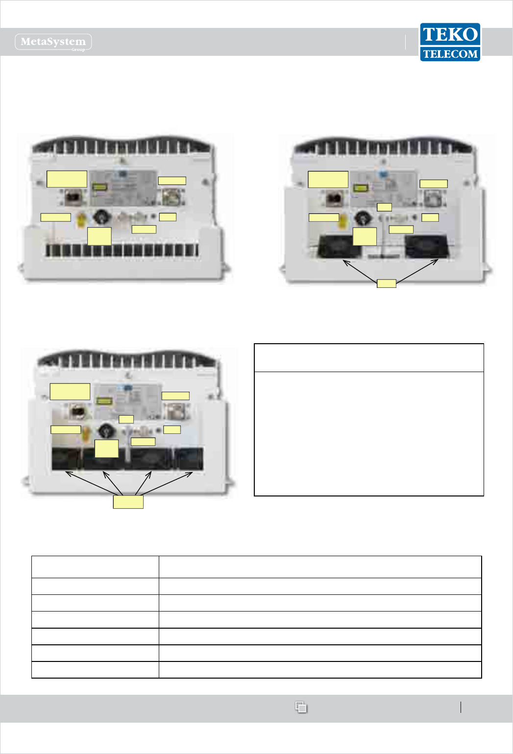
www.tekotelecom.it
www.tekotelecom.it
SIRIUS: Teko Telecom Modular Coverage and Capacity System
Let us repeat !
Doc ID Number 91 080 0781 - Rel. 04 page 62
english
Remote Units External Access Points•
Medium/ High and Very High Power Remote Units External Access Points
GROUND
OPTICAL
DL/UL WDM
ALARM
RF PORT
AC
MAINS
LED
Medium power and Single band high power Remote Units
Bottom view
GROUND
OPTICAL
DL/UL WDM
ALARM
RF PORT
AC
MAINS
LED
FAN
FANS
Dual band/Triband high power Remote Units
Bottom view
Very high power Remote Units and high power Remote Units
equipped with ampliers operating in the LTE2600 band
Bottom view
GROUND
OPTICAL
DL/UL WDM
ALARM
RF PORT
AC
MAINS
LED
FAN
FANS
REMOTE UNIT GENERAL OPERATING STATUS
LED DESCRIPTION LED
Green: regular operation (no alarm)
Blinking Orange: presence of active alarms with
warning severity level (4)
Orange: presence of active alarms with minor
severity level (3)
Blinking Red: presence of active alarms with
major severity level (2)
Red: presence of active alarms with critical
severity level (1)
Connectors Description
RF PORT Down Link/Up Link 7/16 RF connector
OPTICAL DL/UL WDM Optical bres input/output connector
GROUND Equipment grounding
AC MAINS AC voltage input (100-240Vac)
FAN Fans power supply and control connector
ALARM Auxiliary alarms connector (4 in, 4 out)
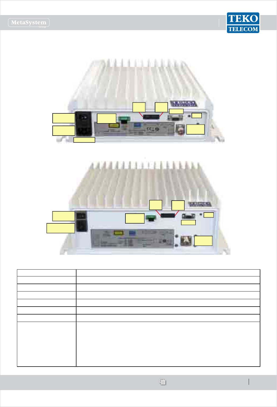
www.tekotelecom.it
www.tekotelecom.it
SIRIUS: Teko Telecom Modular Coverage and Capacity System
Let us repeat !
Doc ID Number 91 080 0781 - Rel. 04 page 63
english
Low Power Remote Units External Access Points (AC Powered)
AC MAINS
MAINS
SOCKET
MAINS
SWITCH
EXT
OUT EXT
IN RS232
RF
PORT
LED
OPTICAL
DL/UL
Single/Dual/Tri-Band Low Power Remote Units External Access Points
Vac MAINS
CONNECTOR
AC MAINS
SWITCH RS232
RF
PORT
LED
OPTICAL
DL/UL
EXT
OUT EXT
IN
Six-Band Low Power Remote Unit External Access Points
Connectors Description
RF PORT Down Link/Up Link RF connector (N type)
OPTICAL DL/UL Optical bres input/output connector
AC MAINS AC voltage input (100-240Vac) and switch
EXT OUT External alarms output connector
EXT IN External alarms input connector
RS 232 9-pole D-Sub RS232 connector for Local Management
LED
Remote Unit general operating status LED
Green: no alarm
Blinking Orange: presence of active alarms with warning severity level (4)
Orange: presence of active alarms with minor severity level (3)
Blinking Red: presence of active alarms with major severity level (2)
Red: presence of active alarms with critical severity level (1)
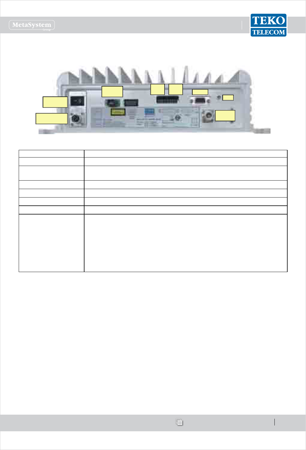
www.tekotelecom.it
www.tekotelecom.it
SIRIUS: Teko Telecom Modular Coverage and Capacity System
Let us repeat !
Doc ID Number 91 080 0781 - Rel. 04 page 64
english
DC Powered Low Power Remote Unit External Access Points
Vdc INPUT
CONNECTOR
48Vdc
SWITCH
EXT
OUT EXT
IN RS232
RF
PORT
LED
OPTICAL
DL/UL
Connectors Description
RF PORT Down Link/Up Link RF connector (N type)
OPTICAL DL/UL Optical bres input/output connector
48V 3A Vdc input connector (48Vdc) and switch
EXT OUT External alarms output connector
EXT IN External alarms input connector
RS 232 9-pole D-Sub RS232 connector for Local Management
LED
Remote Unit general operating status LED
Green: no alarm
Blinking Orange: presence of active alarms with warning severity
level (4)
Orange: presence of active alarms with minor severity level (3)
Blinking Red: presence of active alarms with major severity level (2)
Red: presence of active alarms with critical severity level (1)

www.tekotelecom.it
www.tekotelecom.it
SIRIUS: Teko Telecom Modular Coverage and Capacity System
Let us repeat !
Doc ID Number 91 080 0781 - Rel. 04 page 65
english
Coverage Systems Management and Power Supply1.2.3
Management
Teko Telecom Supervision Module (TSPV) allows the management of the entire Coverage and
Capacity System.
The System Supervision Module is able to manage the Active Subrack it is equipped in (Master
Subrack) and up to other 12 Active Subracks (Monitored Subracks).
Twelve ports (1 to 8 and S1 to S4) are available on the Supervision Module front panel to be
connected to the RS485 ports of monitored Active Subracks.
The ports numbered from 1 to 8 are available for the connection to monitored subracks
mounted within the same rack hosting the Master Subrack.
The other four ports (S1 to S4) are available for the management of remote subracks equipped
with Slave supervision units.
When the Coverage System includes point to point links these ports allow the management
of the Slave Point to Point modules built-in Supervision units. Each Slave Point to Point
module Supervision unit manages the remote optical subrack - hosting the module - and all
connected Remote Units.
The Coverage System Supervision Module communicates with the Slave Point to Point built-
in Supervision via the single-mode optical ber (SMR 9/125) connecting Master and Slave
Point to Point modules.
When the Coverage System does not include point to point links, the master supervision
module communicates with the Remote Units via the single-mode optical ber (SMR 9/125)
connecting Fiber Optic modules to Remote Units.
Address assignement
Each monitored Subrack takes its address from the Supervision Module port it is connected
to (please refer to Paragraph 2.2.2 RS485 Connections for details).
The Active Subrack equipped with the Supervision Module (Master Subrack) takes address
= 0 (zero).
The whole Coverage System can be accessed and managed simply connecting a PC, either
locally or remotely, to the IP address of the System Supervision Module.
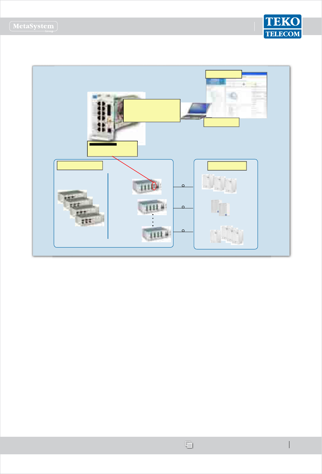
www.tekotelecom.it
www.tekotelecom.it
SIRIUS: Teko Telecom Modular Coverage and Capacity System
Let us repeat !
Doc ID Number 91 080 0781 - Rel. 04 page 66
english
EXAMPLE:
OPTICAL SYSTEM
MANAGEMENT ARCHITECTURE:
Optical System
Supervision Module
Passive RF
Interface
Optical and
Supervision
MASTER
Optical Subrack
Monitored
Optical Subrack
8th Monitored
Optical Subrack
Optical System
MASTER UNIT REMOTE UNITS
Communication interfaces:
Ethernet LAN,
Modem, VPN, PPP
Monitoring PC
Web interface
Local management is performed connecting a PC to the Ethernet port (LAN, RJ45 connector),
available on the Supervision Module front panel. A local connection is required to perform
commissioning.
For remote control the System can be accessed via Ethernet, via external PSTN or wireless
modem or via optional built-in wireless modem.
The management of the System is performed via web pages: the Supervision Module is
equipped with a web-server and each component of the System is associated to a web page
displaying detailed information about the component.
The Supervision Module is also equipped with an SNMP-agent, which allows the control of
each parameter of the system via SNMP get/set/trap operations.
The Supervision Module is also provided with an OpenVPN application that allows remote
and secure access to the System using the Internet.
Teko Telecom Operation and Maintenance Terminal (OMT) web pages show the Coverage
System operating parameters and alarm status. They allow the commissioning, monitoring,

www.tekotelecom.it
www.tekotelecom.it
SIRIUS: Teko Telecom Modular Coverage and Capacity System
Let us repeat !
Doc ID Number 91 080 0781 - Rel. 04 page 67
english
setting and troubleshooting of the whole Coverage System.
Teko Telecom Operation Management Centre (OMC) proprietary software allows the
management of multiple Teko Telecom Coverage and Capacity Systems in a Network.
OMC is a client-server application: the server collects information, such as System status
and alarms, relevant to the Systems in the Network. The Server communicates with each
System Supervision Module via Ethernet (TCP-IP socket) or via PSTN or wireless modem.
The Client provides access to the information stored in the Server database. It allows
end-users to check the status of the Coverage Systems in the Network via a user friendly
graphical interface.
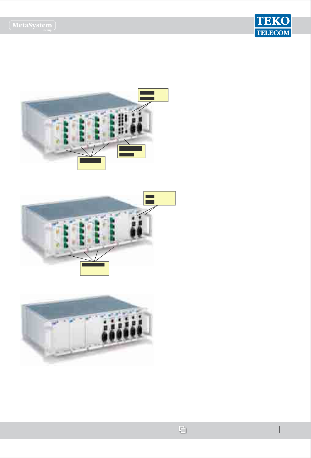
www.tekotelecom.it
www.tekotelecom.it
SIRIUS: Teko Telecom Modular Coverage and Capacity System
Let us repeat !
Doc ID Number 91 080 0781 - Rel. 04 page 68
english
Power Supply
Coverage Systems can be AC or DC powered. Power supply modules can be equipped in
monitored Active Subracks or in the Master Subrack or in dedicated Active Subracks.
Example of Power Supply Modules equipped
in the Master Optical Subrack (the second
Power Supply Module, optional, provides
power supply redundancy for higher
reliability).
Power Supply
Power Supply
Modules
Modules
Fiber Optic
Modules
Supervision
Module
Power Supply
Power Supply
Modules
Modules
Fiber Optic
Fiber Optic
Modules
Example of Power Supply Modules equipped
in a monitored Active Subrack. The RJ45
connector available on the Power Supply
Module front panel can be used for connection
to the Supervision Module, equipped in the
Master Active Subrack.
Example of Power Supply Modules equipped
in a dedicated Active Subrack.
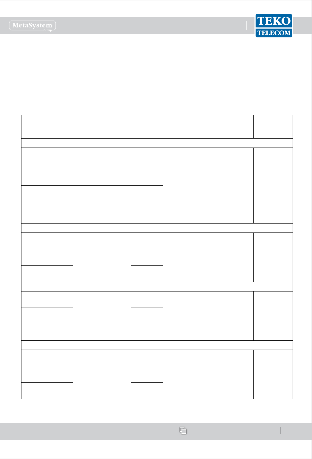
www.tekotelecom.it
www.tekotelecom.it
SIRIUS: Teko Telecom Modular Coverage and Capacity System
Let us repeat !
Doc ID Number 91 080 0781 - Rel. 04 page 69
english
Teko Telecom Coverage Systems Technical Specications1.2.4
This paragraph makes Coverage and Capacity Systems mechanical, environmental and power
supply specications available. Please refer to product datasheets for detailed electrical
specications. Contact Teko Telecom Sales Oce for further information.
Remote Units•
Remote Unit
model
Dimensions
(HxWxD)
Weight Operating
temperature
range
Degree of
protection
(IP)
Power supply
LOW POWER
Single / Dual /
Triband
350x350x100mm
(13.78x13.78x3.94 in)
max volume - heat
sinks and connectors
included
13 kg
(28.7 lbs)
-20°C up to +55°C
(-4°F up to +131°F)
IP32 (box)
IP66 (with
optional pro-
tection kit)
85÷264Vac
(50-60Hz)
AC version
-72 ÷ -36Vdc
DC version
6-band 395 x 414 x 144 mm
(15.55 x 16.30 x 5.67in)
max volume - heat
sinks and connectors
included
19 kg
(41.9lbs)
MEDIUM POWER
Triband 570x415x260mm
(22.44x16.34x10.24 in)
max volume - heat
sinks, handles and
connectors included
30 kg
(66.1 lbs)
-20°C up to +55°C
(-4°F up to +131°F)
IP66 85÷264Vac
(50-60Hz)
Dual band 28 kg
(61.73 lbs)
Single band 26 kg
(57.32 lbs)
HIGH POWER
Triband 570x415x260mm
(22.44x16.34x10.24 in)
max volume - heat
sinks, handles and
connectors included
32 kg
(70.5 lbs)
-20°C up to +55°C
(-4°F up to +131°F)
IP66 85÷264Vac
(50-60Hz)
Dual band 30 kg
(66.1 lbs)
Single band 28 kg
(61.73 lbs)
VERY HIGH POWER
Triband 620x415x260mm
(24.41x16.34x10.24 in)
max volume - heat
sinks, handles and
connectors included
38 kg
(83.78 lbs)
-20°C up to +55°C
(-4°F up to +131°F)
IP66 85÷264Vac
(50-60Hz)
Dual band 37 kg
(81.57 lbs)
Single band 36 kg
(79.37 lbs)

www.tekotelecom.it
www.tekotelecom.it
SIRIUS: Teko Telecom Modular Coverage and Capacity System
Let us repeat !
Doc ID Number 91 080 0781 - Rel. 04 page 70
english
System Subracks•
Dimensions 19” - 3U racks / depth 270 mm (10.63 in) - Active and Passive
Subracks
19” - 2U rack / depth 360 mm (14.17 in) - Service Front End Subrack
19” - 1U rack / depth 270 mm (10.63 in) - Forced-Air Cooling Subrack
Power supply (Active Subracks) 85÷264Vac (50-60Hz) (TPSU/AC)
-72÷-36Vdc (TPSU/48)
Operating temperature range -5°C up to +55°C (+23°F up to +131°F) with proper forced-air cooling

www.tekotelecom.it
www.tekotelecom.it
Let us repeat !
Doc ID Number 91 080 0781 - Rel. 04
english
SIRIUS: Teko Telecom Modular Coverage and Capacity System
2.System Installation
2.System Installation
2.System Installation
2.System Installation
2.System Installation
2.System Installation
2.System Installation
2.System Installation
2.System Installation
2.System Installation
2.System Installation
2.System Installation
2.System Installation
2.System Installation
2.System Installation
2.System Installation
2.System Installation
2.System Installation
2.System Installation
2.System Installation
2.System Installation
2.System Installation
2.System Installation
2.System Installation
2.System Installation
2.System Installation

www.tekotelecom.it
www.tekotelecom.it
SIRIUS: Teko Telecom Modular Coverage and Capacity System
Let us repeat !
Doc ID Number 91 080 0781 - Rel. 04 page 72
english
System Installation2.
Before installing the equipment, carefully read the safety rules herewith attached.
A correct system installation and setting procedure requires a good knowledge and
experience in installing telecommunication equipment. These activities should be
performed by skilled personnel only.
A cabinet cooling forced air ventilation system, able to provide an air ow of up to 180cfm
(5m3/min), is required to ensure cabinet installed equipment proper operation.
In Finland, Norway and Sweden, the equipment is intended to be installed in RAL (Restricted
Access Location), where the equipotential bonding has been applied.
The RESTRICTED ACCESS LOCATION is a location for equipment where both of the
following apply:
- access can only be gained by SERVICE PERSONS or by USERS who have been
instructed about the reasons for the restrictions applied to the location and about
any precautions that shall be taken; and
- access is through the use of a TOOL or lock and key, or other means of security, and
is controlled by the authority responsible for the location.
In Finland, Norway and Sweden, the equipment intended for connection to other equipment
or a network shall have a marking stating that the equipment must be connected to an
earthed mains socket-outlet.
In Finland: “Laite on liitettävä suojamaadoituskoskettimilla varustettuun
pistorasiaan”
In Norway: “Apparatet må tilkoples jordet stikkontakt”
In Sweden: “Apparaten skall anslutas till jordat uttag”
Initial Check
Make sure that the supply is complete and/or that the material has not been damaged during
transport.
The list of the materials that make up the equipment is described in the relative PACKING LIST.
Should any parts be missing, or should some be damaged, kindly inform the Sales Dept. of
Teko Telecom immediately, in order to facilitate replacing and/or repairing involved parts.
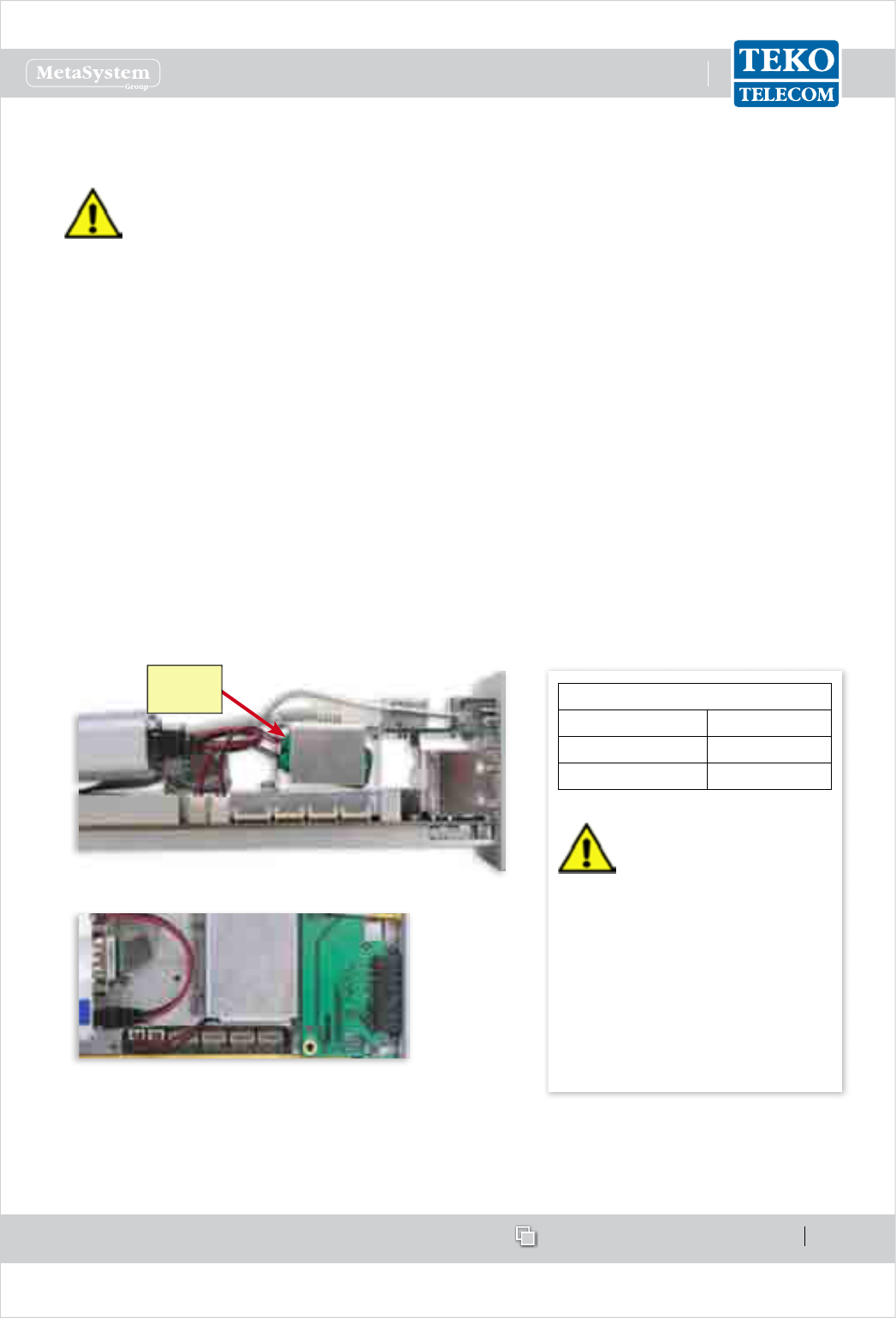
www.tekotelecom.it
www.tekotelecom.it
SIRIUS: Teko Telecom Modular Coverage and Capacity System
Let us repeat !
Doc ID Number 91 080 0781 - Rel. 04 page 73
english
Mechanical Installation2.1
Before starting mechanical installation, make sure that the components of the
System are not powered.
Master Units: make sure that the switches of all the power supply modules equipped
in the System are set to O (OFF).
Remote Units: make sure that Remote Units are not connected to the MAINS.
Please Note
If the Supervision Module is equipped with the optional wireless modem and/or the optional
battery backup, before starting the System installation, please activate the options as follows:
Battery backup option > : the two internal backup batteries are not connected to the
Supervision board in order to prevent batteries from discharging during shipment. To
activate the option, perform the following steps:
Remove the Supervision module (if necessary): loosen the four screws that x the module 1.
to the Subrack and carefully slide the module forward.
Connect the terminals of the two backup batteries to the J9 and J10 connectors, available 2.
on the Supervision board.
Please refer to the following gures for details about the cabling.
Backup
batteries
Backup battery and Supervision board connections - Side view
Backup Battery and Supervision board connections - Top view
If the 3. optional wireless modem is equipped inside the Supervision module, please refer
to the following procedure to insert the SIM card, otherwise carefully slide the Supervision
module back into the slot and x its position tightening the 4 screws.
BACKUP BATTERY SPECIFICATIONS
Nominal Voltage 3.7 V
Nominal Capacity > 1100 mAh
Type Rechargeable
CAUTION
Risk of explosion if battery is replaced
by an incorrect type.
Dispose of used batteries according to
the instructions.
Backup Batteries Installation and
replacement should be performed
by skilled personnel only.
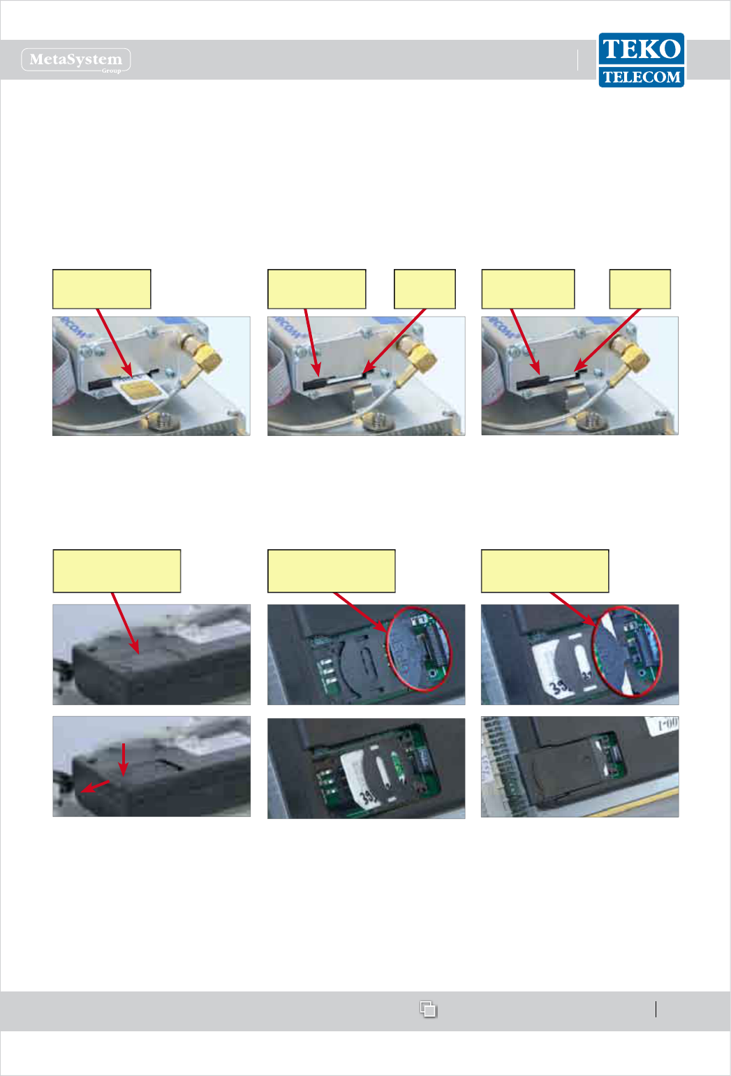
www.tekotelecom.it
www.tekotelecom.it
SIRIUS: Teko Telecom Modular Coverage and Capacity System
Let us repeat !
Doc ID Number 91 080 0781 - Rel. 04 page 74
english
Wireless modem > option: to insert the wireless modem SIM card perform the following
steps:
Remove the Supervision module (if necessary): loosen the four screws that x the module 1.
to the Active Subrack and carefully slide the module forward.
Insert the SIM card into the wireless modem.2.
GSM/GPRS modem•
Insert the SIM card (PIN code
disabled / data transfer enabled),
with the gold side up, into the
modem dedicated card slot.
Push the SIM card into the slot until
it clicks into place. The SIM card slot
is provided with a lock switch (black
slider on the left of the SIM slot).
SIM card
in place
SIM lock switch
opened
Close the SIM lock switch.
Move the black slider to the right
position.
The SIM card is locked in place.
SIM card
locked
SIM lock
switch closed
SIM card -
gold side up
UMTS modem•
Remove the SIM card holder
cover.
To avoid damages to the cover,
press lightly and slide the cover
away as shown in gure.
SIM card holder
cover
Slide the SIM card holder to the
open position and lift it up.
Slide the SIM card (PIN code
disabled/data transfer enabled for
3G operation) into the card holder.
SIM card holder -
open position
Lower the SIM card holder and
slide it back to the lock position.
Replace the card holder cover,
sliding it into position carefully,
until it clicks.
SIM card holder -
lock position
Carefully slide the Supervision module back into the slot and x its position tightening the 3.
4 screws.

www.tekotelecom.it
www.tekotelecom.it
SIRIUS: Teko Telecom Modular Coverage and Capacity System
Let us repeat !
Doc ID Number 91 080 0781 - Rel. 04 page 75
english
Positioning Master Unit Subracks2.1.1
The modular Master Unit is composed of 19” subracks (N3 compatible). So, it needs to be
positioned indoor or inside cabinets to guarantee the protection of the equipment against
atmospheric agents, humidity and temperature changes.
Fasten the rack cabinet, so as to prevent it from turning over.1.
Connect the cabinet to the station ground.2.
Position the subracks inside the cabinet as follows:3.
mount the horizontal rails for support of the equipment;•
insert each subrack into the rails and slide it into position carefully. Leave one unit distance •
between active subracks for air ow to assure proper cooling;
x each subrack to the vertical mounting guides of the cabinet using four screws, to be •
inserted into the proper slots;
connect each subrack to the cabinet ground bus bar;•
insert the modules and tighten the screws available on the module front panel to fasten •
the module to the subrack.
Please note
Make sure that the System is equipped with the same type of Power Supply modules (same
commercial code on handles).
To make connections easier, position the subracks as follows:
the Service Front End subrack should be positioned over the subrack / subracks hosting •
RF interface modules (with TDFE subracks over POI subracks);
the subracks hosting RF interface modules and/ or passive components should be •
positioned over Optical Subracks;
the subracks hosting Power Supply modules should be installed in the lower position. •
Power supply modules providing power supply to other active subracks should be
grouped on the right side of the subrack;
the forced-air cooling subrack should be installed below the subracks hosting Power •
Supply modules, in order to ensure the air ow volume required for the equipment proper
operation.
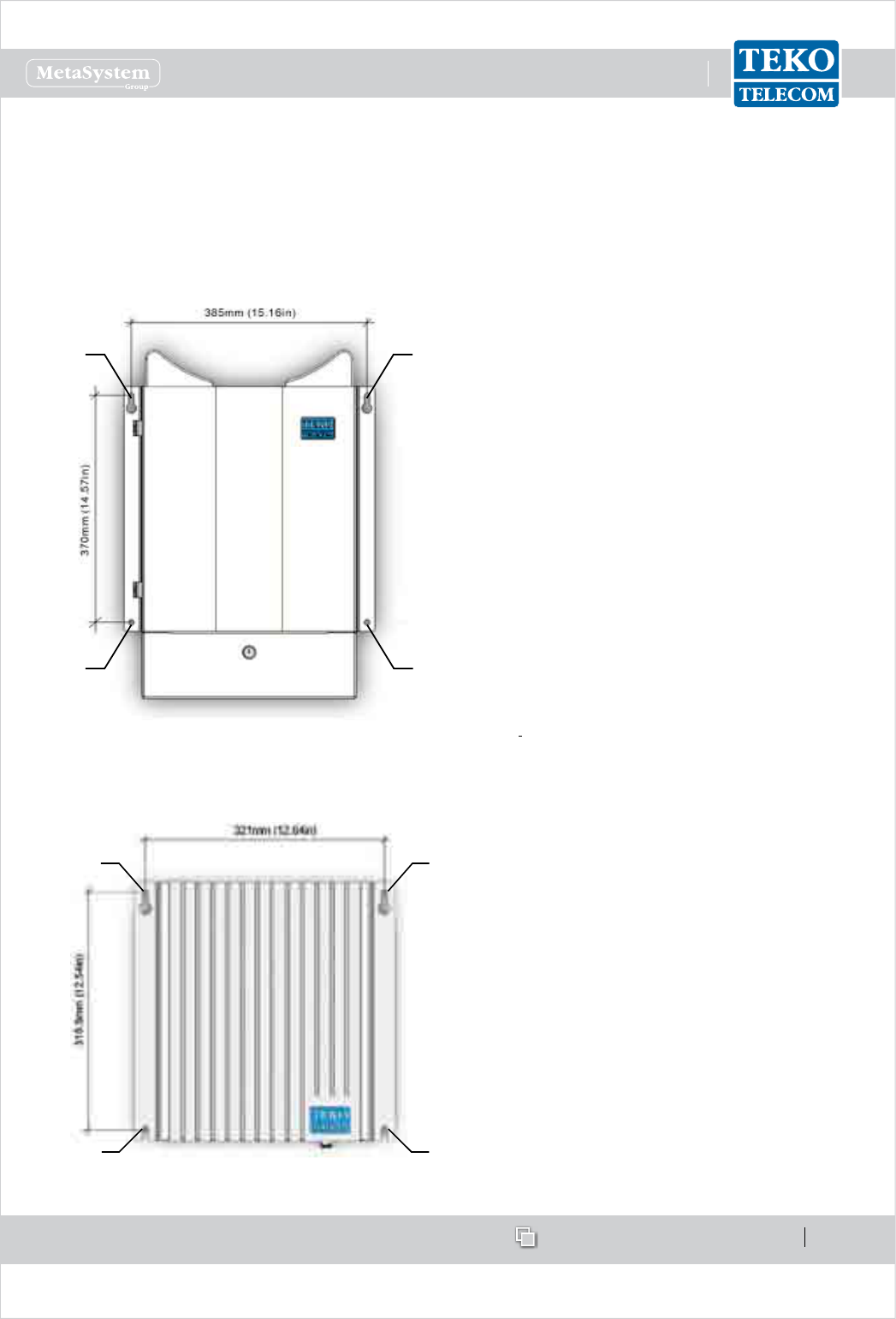
www.tekotelecom.it
www.tekotelecom.it
SIRIUS: Teko Telecom Modular Coverage and Capacity System
Let us repeat !
Doc ID Number 91 080 0781 - Rel. 04 page 76
english
Positioning Remote Units2.1.2
Remote Units can be installed either outdoor (on a wall or pole) or inside specic cabinets. Very
High/High/Medium power Remote Unit weatherproof IP66 case is equipped with handles to
make mounting easier. Very High/High/Medium power Remote Units xing holes position is
shown in the following gure.
Dimensions (max volume - heat sinks, han-
dles and connectors included)
HIGH/MEDIUM POWER REMOTE UNIT•
approx 570 x 415 x 260 mm (22.44 x 16.34
x 10.24 in)
VERY HIGH POWER REMOTE UNIT•
approx 620 x 415 x 260 mm (24.41 x 16.34
x 10.24 in)
Weight
approx 30 kg (66.14 lbs) - Triband Medium •
Power Remote Unit
approx 32 kg (70.55 lbs) - Triband High •
Power Remote Unit
approx 38 Kg (83.78 lbs) - Triband Very •
High Power Remote Unit
AA
BB
POSITION OF THE PRECUT SLOTS IN THE EQUIPMENT SUPPORT BRACKETS
The SINGLE/DUAL/TRIBAND Low power Remote Units xing holes position is shown in the
following gure.
SINGLE/DUAL/TRIBAND REMOTE UNITS
Dimensions (max volume - heat sinks
and connectors included):
approx 350 x 350 x 100mm (13.78 x
13.78 x 3.94 in)
Weight
approx 13 kg (28.7 lbs) - Single/Dual/
Triband Low Power Remote Unit
POSITION OF THE PRECUT SLOTS IN THE EQUIPMENT SUPPORT BRACKETS
A
B B
A
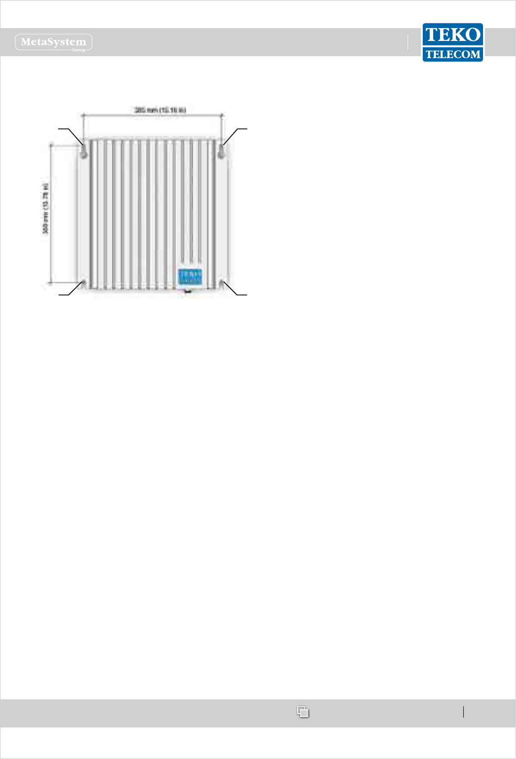
www.tekotelecom.it
www.tekotelecom.it
SIRIUS: Teko Telecom Modular Coverage and Capacity System
Let us repeat !
Doc ID Number 91 080 0781 - Rel. 04 page 77
english
The SIX-BAND Low power Remote Unit xing holes position is shown in the following gure.
6-BAND REMOTE UNITS
Dimensions (max volume - heat sinks
and connectors included):
approx 395 x 414 x 144 mm (15.55 x
16.30 x 5.67in)
Weight
approx 19 kg (41.9lbs)
POSITION OF THE PRECUT SLOTS IN THE EQUIPMENT SUPPORT BRACKETS
A
BB
A
Remote Units have to be xed in vertical position on the wall or pole, or on the vertical guides
present inside the cabinet.
WALL MOUNTING
Mark the four pre-cut slots position•
Drill 4 holes at the marked position•
Insert the dowels into the 4 holes•
Screw 2 M8 screws into the 2 upper dowels•
Hang the Remote Unit inserting the upper pre-cut slots (ref. A) through the screws•
Fix the equipment position with other 2 M8 screws to be inserted through the lower pre-•
cut slots (ref. B) into the lower holes
After checking the correct positioning of the equipment, fully tighten the screws.•
POLE MOUNTING: a pole mounting kit is available (option).
Adequate Remote Units mounting is checked by the following test: a force, in addition to
the weight of the equipment, is applied downwards through the centre of gravity of the
equipment, for 1minute. The additional force shall be equal to three (3) times the weight of
the equipment but not less than 50N. The equipment shall remain secure during the test.

www.tekotelecom.it
www.tekotelecom.it
SIRIUS: Teko Telecom Modular Coverage and Capacity System
Let us repeat !
Doc ID Number 91 080 0781 - Rel. 04 page 78
english
IP66 PROTECTION KIT MOUNTING LOW POWER REMOTE UNITS
A protection kit, providing IP66 protection degree, is available as option for Low Power Remote
Units outdoor or harsh environment installation.
Protection kit mounting instructions
Lead the equipment external connection cables through the cable glands, available on •
the bottom of the IP66 protection kit.
When the Commissioning of the equipment has been completed• , carefully slide the
IP66 kit upwards and tighten the cable glands until the gasket of the lead-through is
tightly around the cable.
Fully tighten the 4 screws available inside the 4 xing holes of the IP66 kit to fasten the kit •
to the Unit - tool: 4mm (0.16in) Allen key.
To remove the kit, loosen the 4 screws xing the kit to the Unit, loosen the cable glands and
carefully slide the kit downwards.

www.tekotelecom.it
www.tekotelecom.it
SIRIUS: Teko Telecom Modular Coverage and Capacity System
Let us repeat !
Doc ID Number 91 080 0781 - Rel. 04 page 79
english
Connections2.2
The following connections must be performed:
RF connections•
RF connections change according to the application scenario. This document describes how
to:
Connect RF interface modules (TDFE modules or Point of Interface modules) to 1. a single
Fiber Optic Transmitter/Receiver Module (Optical Systems).
Connect RF interface modules to Master Point to Point modules.2.
Connect RF interface modules to Passive Modules providing distribution and ltering and 3.
Passive Modules to Optical Modules- Fiber Optic Transmitter/Receiver Modules or Master
Point to Point modules (Optical Systems).
Connect the Slave Point to Point module, equipped in a remote optical subrack, to Fiber 4.
Optic Transmitter/Receiver Modules.
Connect TSFE subracks to TDFE modules (Optical Systems and Modular Repeaters) and to 5.
Passive Modules providing distribution and ltering (Optical Systems).
Connect the equipment providing coverage (TSFE subracks and Remote Units) to the 6.
Antenna System.
RS485 connections•
Monitored Active Subracks have to be connected to the System Supervision Module (Optical
Systems and Repeaters);
OPTICAL connections•
Remote Units have to be connected to Optical Subracks via ber optics (Optical Systems).
When the Coverage System includes point to point links, the Master and Slave Point to Point
modules have to be connected via ber optics.
Power Supply connections•
Active Subracks and Remote Units have to be connected to their power supply sources
(Optical Systems and Repeaters).
Please Note
In any event, the installer should never connect an antenna to the Master Unit BTS port.
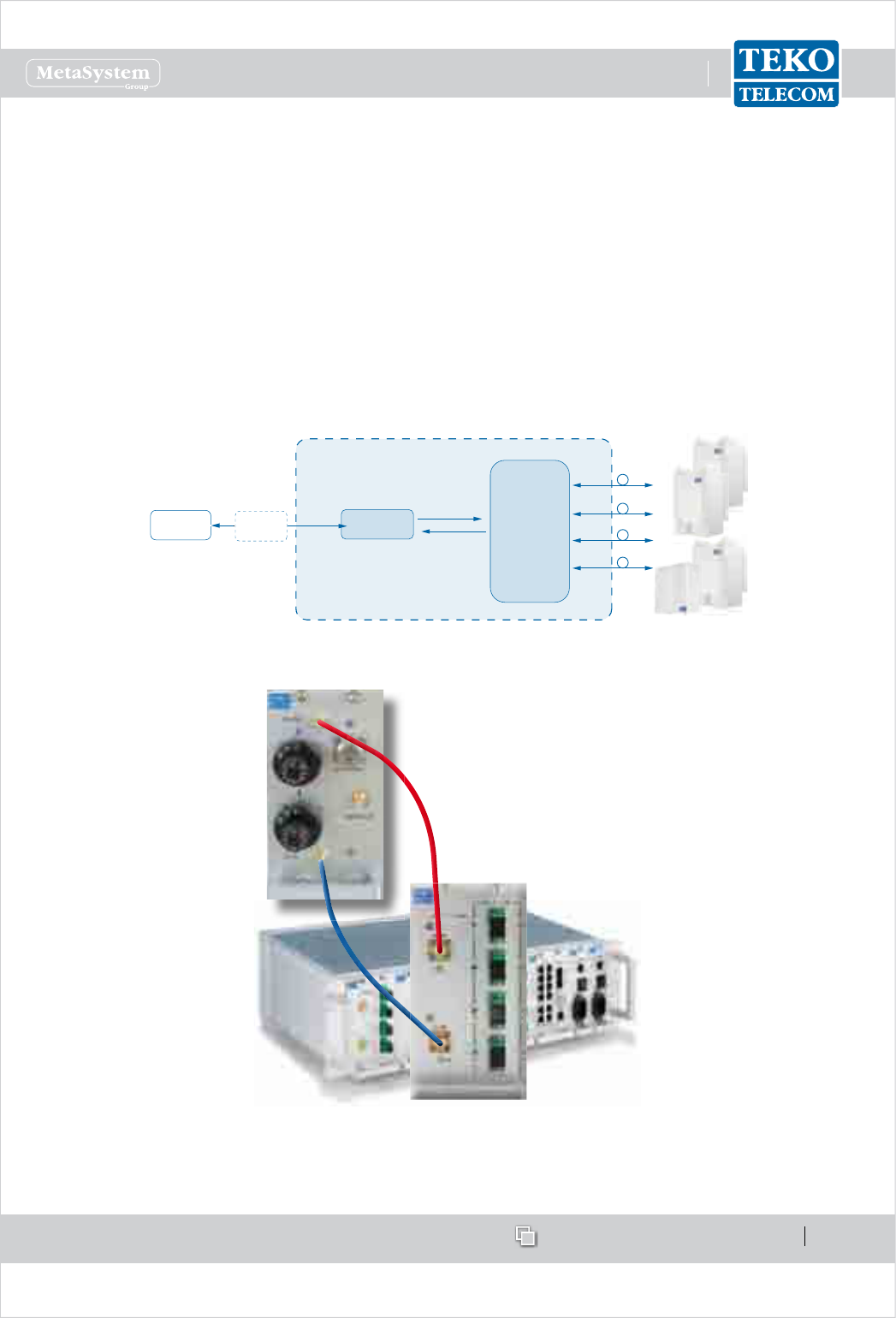
www.tekotelecom.it
www.tekotelecom.it
SIRIUS: Teko Telecom Modular Coverage and Capacity System
Let us repeat !
Doc ID Number 91 080 0781 - Rel. 04 page 80
english
RF Connections2.2.1
Connecting RF interface modules (TDFE modules or Point of Interface modules) to a 1.
single Optical Module
The typical scenario for this module application is the single operator / single band Optical
System. The RF interface subrack is equipped either with one POI module or with one Donor
Front End module (single operator / single band Optical Systems). The Master Unit can drive
1 Fiber Optic Transmitter/Receiver Module (i.e. up to 4 Remote Units or up to 5 cascaded
Remote Units).
POI module driving a single Fiber Optic Transmitter/Receiver•
BTS or Node B POI MODULE
FIXED
ATTENUATOR
FIBER OPTIC
TRANSMITTER
RECEIVER
MODULE
TO/FROM
REMOTE UNITS
Example - Block diagram of single operator/single band Systems equipped with one POI module
Connections
Connect the POI module DL OUT connector to the Optical module DL RF connector (red line).
Connect the POI module UL IN connector to the Optical module UL RF connector (blue line).
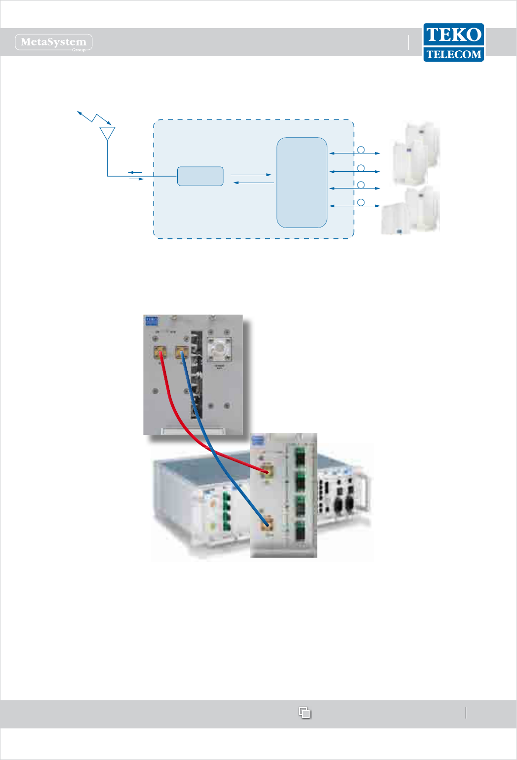
www.tekotelecom.it
www.tekotelecom.it
SIRIUS: Teko Telecom Modular Coverage and Capacity System
Let us repeat !
Doc ID Number 91 080 0781 - Rel. 04 page 81
english
TDFE module driving a single Fiber Optic Transmitter/Receiver•
FIBER OPTIC
TRANSMITTER
RECEIVER
MODULE
TO/FROM
REMOTE UNITS
Donor
Antenna
TDFE MODULE
Example - Block diagram of single operator/single band Systems equipped with one DFE module
Connections
Connect the TDFE module DL output connector to the Optical module DL RF input connector
(red line).
Connect the TDFE module UL input connector to the Optical module UL RF output connector
(blue line).
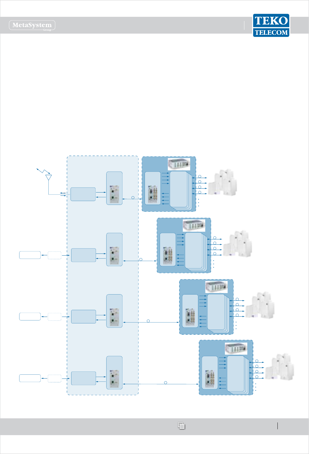
www.tekotelecom.it
www.tekotelecom.it
SIRIUS: Teko Telecom Modular Coverage and Capacity System
Let us repeat !
Doc ID Number 91 080 0781 - Rel. 04 page 82
english
Connecting RF interface modules (TDFE modules or Point of Interface modules) to 2.
Master Point to Point modules
The typical scenario for a point to point link application is an Optical System providing coverage
to several separate buildings (up to 4); in this application the transmission of signals from/to a
group of remote units over a single optical bre allows a signicant reduction in the number
of ber optics running long distances. The point to point link requires the RF interface subracks
to be equipped with the Master Point to Point module and the remote optical subracks to be
equipped with the Slave Point to Point modules.
An Optical System serving 4 remote optical subracks via point to point optical links is provided
as example.
RF INTERFACE SUBRACK
BTS or Node B
FIXED
ATTENUATOR
TDFE MODULE
Band 1
Donor
Antenna
POI MODULE
Band 2
FIBER OPTIC
TRANSMITTER
RECEIVER
MODULES
TO/FROM
REMOTE UNITS
MASTER
POINT TO POINT
MODULE
SLAVE
POINT TO POINT
MODULE
POINT TO
POINT
OPTICAL LINK
REMOTE OPTICAL
SUBRACK 1
FIBER OPTIC
TRANSMITTER
RECEIVER
MODULES
TO/FROM
REMOTE UNITS
MASTER
POINT TO POINT
MODULE
SLAVE
POINT TO POINT
MODULE
POINT TO
POINT
OPTICAL LINK
REMOTE OPTICAL
SUBRACK 2
BTS or Node B
FIXED
ATTENUATOR
POI MODULE
Band 3
FIBER OPTIC
TRANSMITTER
RECEIVER
MODULES
TO/FROM
REMOTE UNITS
MASTER
POINT TO POINT
MODULE
SLAVE
POINT TO POINT
MODULE
POINT TO
POINT
OPTICAL LINK
REMOTE OPTICAL
SUBRACK 3
BTS or Node B
FIXED
ATTENUATOR
POI MODULE
Band 4
FIBER OPTIC
TRANSMITTER
RECEIVER
MODULES
TO/FROM
REMOTE UNITS
MASTER
POINT TO POINT
MODULE
SLAVE
POINT TO POINT
MODULE
POINT TO
POINT
OPTICAL LINK
REMOTE OPTICAL
SUBRACK 4
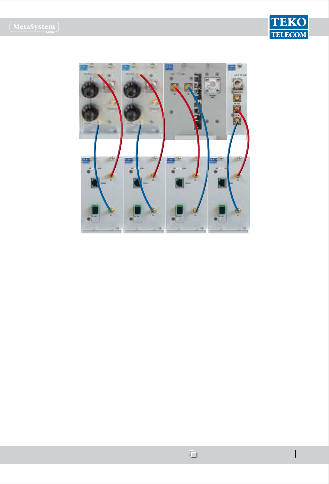
www.tekotelecom.it
www.tekotelecom.it
SIRIUS: Teko Telecom Modular Coverage and Capacity System
Let us repeat !
Doc ID Number 91 080 0781 - Rel. 04 page 83
english
Connections
POI and TAPOI modules -
Connect the Point of Interface module DL OUT connector to the DL connector of the Master PTP
module to be connected to the remote optical subrack to be served by the Point of Interface
(red lines).
Connect the Point of Interface module UL IN connector to the UL connector of the Master PTP
module to be connected to the remote optical subrack to be served by the Point of Interface
(blue lines).
TDFE modules -
Connect the Donor Front End DL connector to the DL connector of the Master PTP module to be
connected to the remote optical subrack to be served by the DFE (red lines).
Connect the Donor Front End UL connector to the UL connector of the Master PTP module to
be connected to the remote optical subrack to be served by the DFE (blue lines).

www.tekotelecom.it
www.tekotelecom.it
SIRIUS: Teko Telecom Modular Coverage and Capacity System
Let us repeat !
Doc ID Number 91 080 0781 - Rel. 04 page 84
english
Connecting3. RF Interface Modules TDFE modules or Point of Interface modules to
Passive Modules providing distribution and ltering and Passive Modules to Optical
Modules- Fiber Optic Transmitter/Receiver Modules or Master Point to Point Modules
(Optical Systems)
Due to the exible conguration options of Teko Telecom Coverage and Capacity Systems,
the same passive modules can be used for dierent purposes:
the 4-way splitter/combiner can be used to manage:•
one RF Interface module and multiple Fiber Optic Modules - Fiber Optic Transmitter/ -
Receiver Modules or Master Point to Point Modules (Single Operator / Single Band
Systems);
multiple RF interface modules TDFE and/or Point of Interface modules) operating in -
the same band (Multi-Operator Systems).
the triplexer can be used to manage:•
up to 3 RF interface modules (TDFE and/or Point of Interface modules) operating in -
dierent bands and up to 4 Fiber Optic Modules or
up to 3 four-way splitter/combiner - used to manage multiple RF interface modules -
(up to 4 for each band) - and up to 4 Fiber Optic Modules, or
up to 3 Service Front Ends operating in dierent bands and up to 4 Fiber Optic -
Modules.
the Pentaplexer and Esaplexer can be used to manage•
up to 5 (Pentaplexer)/ up to 6 (Esaplexer) RF interface modules operating in dierent -
bands or
up to 5 (Pentaplexer)/ up to 6 (Esaplexer) Service Front End subracks operating in -
dierent bands or
up to 5 (Pentaplexer)/ up to 6 (Esaplexer) four-way splitter/combiner modules- used -
to manage multiple RF interface modules (up to 4 for each band).
Connections change according to the application scenario: the following describes the
connection mode for dierent modules applications.
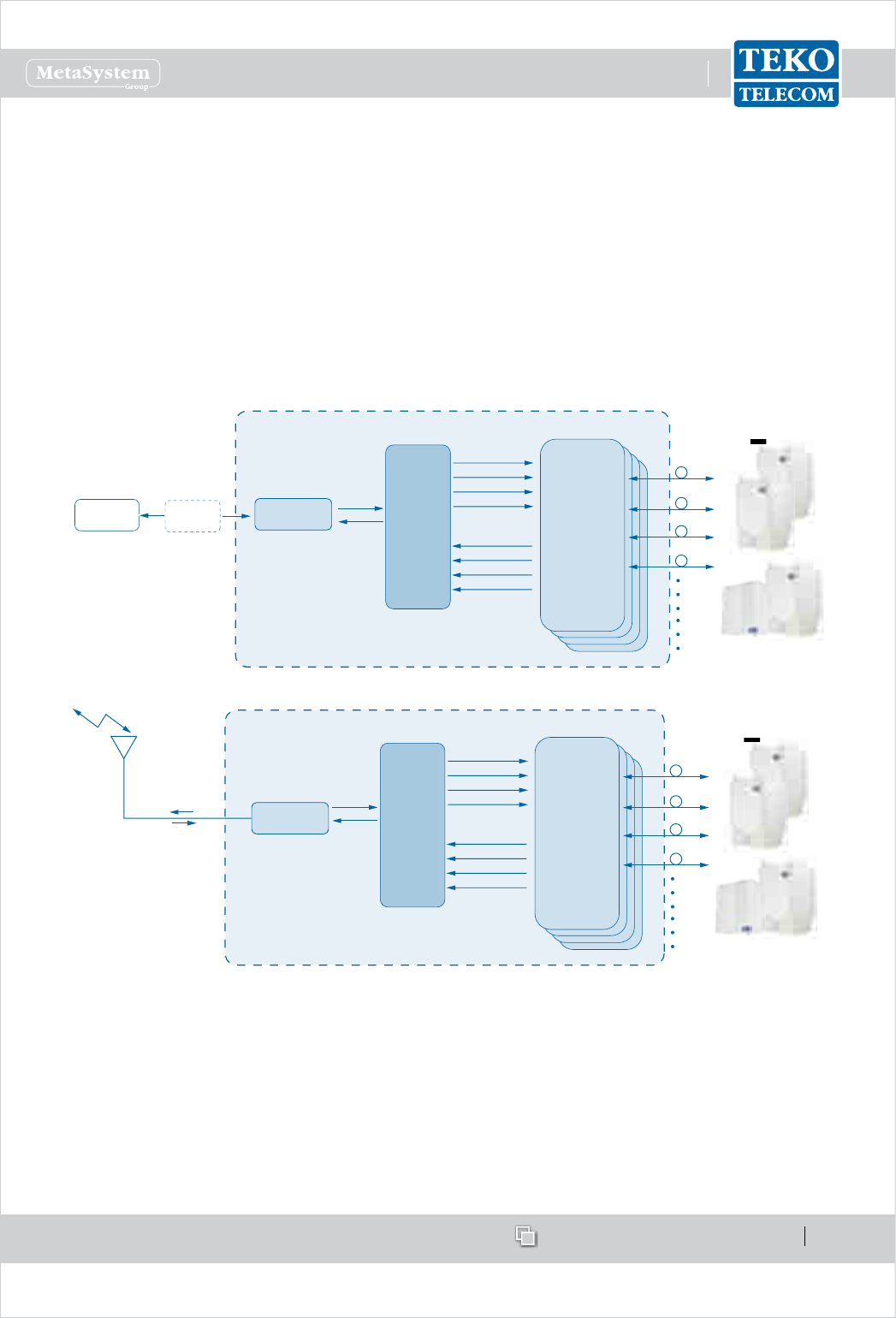
www.tekotelecom.it
www.tekotelecom.it
SIRIUS: Teko Telecom Modular Coverage and Capacity System
Let us repeat !
Doc ID Number 91 080 0781 - Rel. 04 page 85
english
4-way splitter/combiner used to manage 1 RF Interface module and Application A.
multiple Fiber Optic Transmitter/Receiver modules
The typical scenario for this module application is the single operator / single band Optical
System.
The RF interface subrack is equipped with
either one POI (TAPOI) module or one TDFE module,•
the 4-way combiner / splitter to manage up to 4 Fiber Optic Transmitter/Receiver Modules •
(i.e. up to 16 Remote Units).
4-WAY
SPLITTER
COMBINER USED
TO MANAGE
UP TO 4 FIBER
OPTIC MODULES
BTS or Node B POI MODULE
FIXED
ATTENUATOR
FIBER OPTIC
TRANSMITTER
RECEIVER
MODULES
TO/FROM
REMOTE UNITS
REMOTE UNITS
4-WAY
SPLITTER
COMBINER USED
TO MANAGE
UP TO 4 FIBER
OPTIC MODULES
FIBER OPTIC
TRANSMITTER
RECEIVER
MODULES
TO/FROM
REMOTE UNITS
REMOTE UNITS
TDFE MODULE
Donor
Antenna
Examples - Block diagrams of single operator/single band Systems equipped with the 4-way combiner/splitter
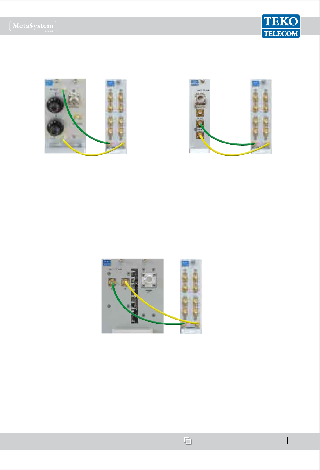
www.tekotelecom.it
www.tekotelecom.it
SIRIUS: Teko Telecom Modular Coverage and Capacity System
Let us repeat !
Doc ID Number 91 080 0781 - Rel. 04 page 86
english
Connections
Connecting POI/TAPOI modules to the 4-way splitter/combiner•
Connecting a TAPOI module to
the 4-way splitter/combiner
Connecting a POI module to the
4-way splitter/combiner
Connect the POI (TAPOI) module DL OUT connector to the 4-way combiner/splitter DL
COMMON input connector (green line).
Connect the 4-way combiner/splitter UL COMMON output connector to the POI (TAPOI)
module UL IN connector (yellow line).
Connecting TDFE modules to the 4-way splitter/combiner•
Connect the DFE module DL connector to the 4-way combiner/splitter DL COMMON input
connector (green line).
Connect the 4-way combiner/splitter UL COMMON output connector to the POI module UL
connector (yellow line).
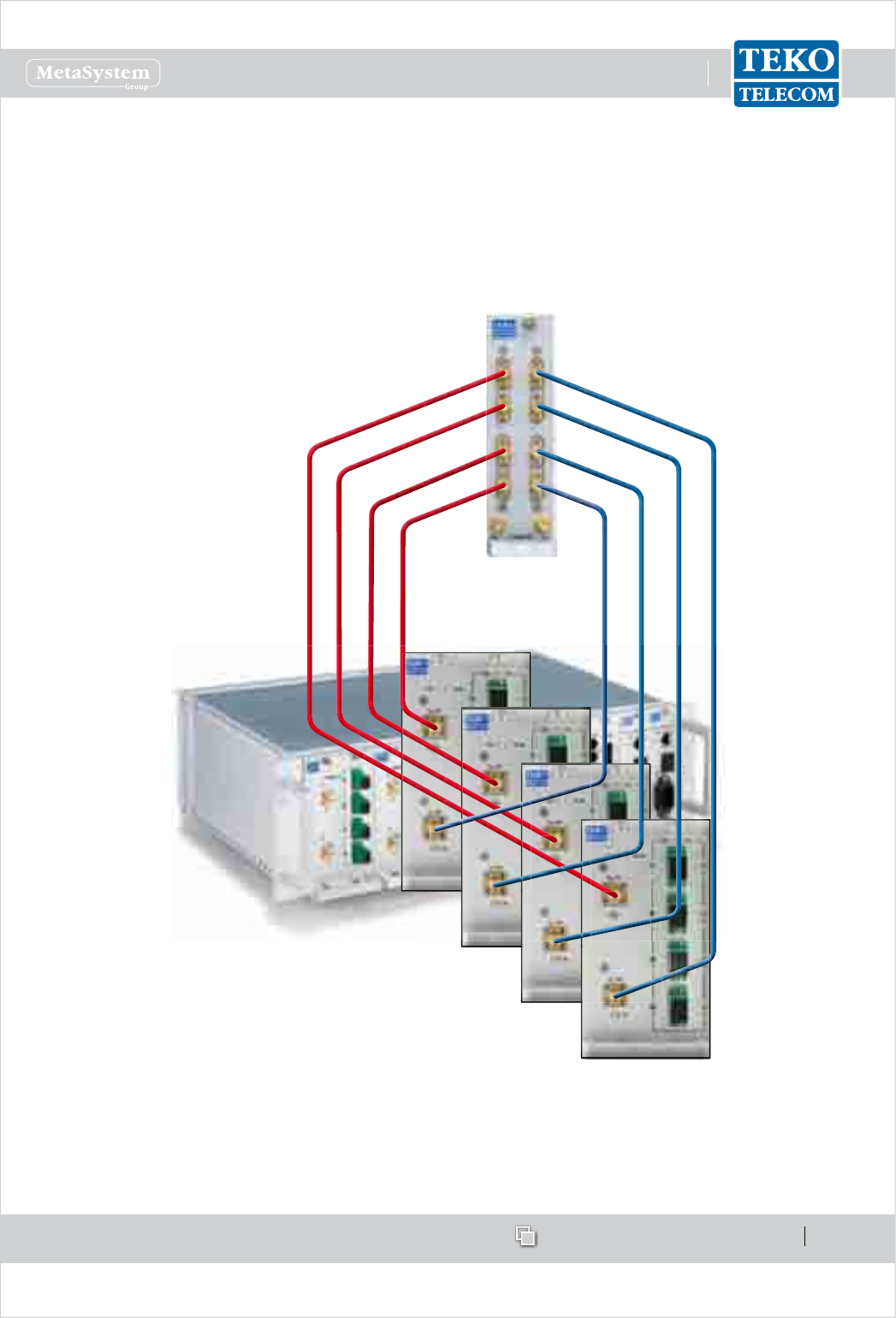
www.tekotelecom.it
www.tekotelecom.it
SIRIUS: Teko Telecom Modular Coverage and Capacity System
Let us repeat !
Doc ID Number 91 080 0781 - Rel. 04 page 87
english
Connecting the 4-way splitter/combiner to Fiber Optic Transmitter/Receiver modules:•
Connect each Fiber Optic Transmitter/Receiver Module DL RF input connector to one of the
4-way combiner/splitter DL output connectors (red lines).
Connect each Fiber Optic Transmitter/Receiver Module UL RF output connector to one of the
4-way combiner/splitter UL input connectors (blue lines).
Please Note
Each 4-way splitter/combiner output/input connector not connected to ber optic modules,
must be charged with a 50Ω dummy load.
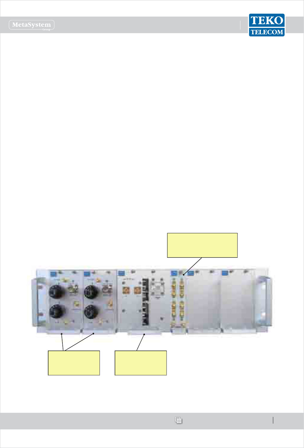
www.tekotelecom.it
www.tekotelecom.it
SIRIUS: Teko Telecom Modular Coverage and Capacity System
Let us repeat !
Doc ID Number 91 080 0781 - Rel. 04 page 88
english
4-way splitter/combiner used to manage multiple RF Interface modules Application B.
operating in the same band
The typical scenario for this module application is the multi operator / single band Optical
System: the RF Interface subracks can be equipped with
up to 4 RF Interface modules operating in the same band: 1 POI module or 1 TDFE module •
for each operator to be extended
the 4-way combiner / splitter used to manage the RF Interface modules and one optical •
subrack equipped with one Fiber Optic Transmitter/Receiver Module.
Another 4-way combiner/splitter module can be equipped to handle up to 4 Fiber Optic
Transmitter/Receiver Modules (please refer to Application A).
The 3-operator / EGSM RF interface equipped with 2 POI modules and 1 TDFE module is
provided as example: it can be housed in 1 space-optimized 19”-3U subrack equipped with:
the 4-way combiner/splitter module and•
3 RF Interface modules operating in the same band (GSM or DCS or UMTS - AMPS or PCS •
or AWS).
The 4-way combiner/splitter module managing up to 4 Fiber Optic Transmitter/Receiver
Modules can be housed in the same subrack.
4-way splitter/combiner
used to manage multiple
RF Interface modules
POI modules
operating in the
EGSM band
DFE module
operating in the
EGSM band
Example: 3-operator / EGSM RF interface layout
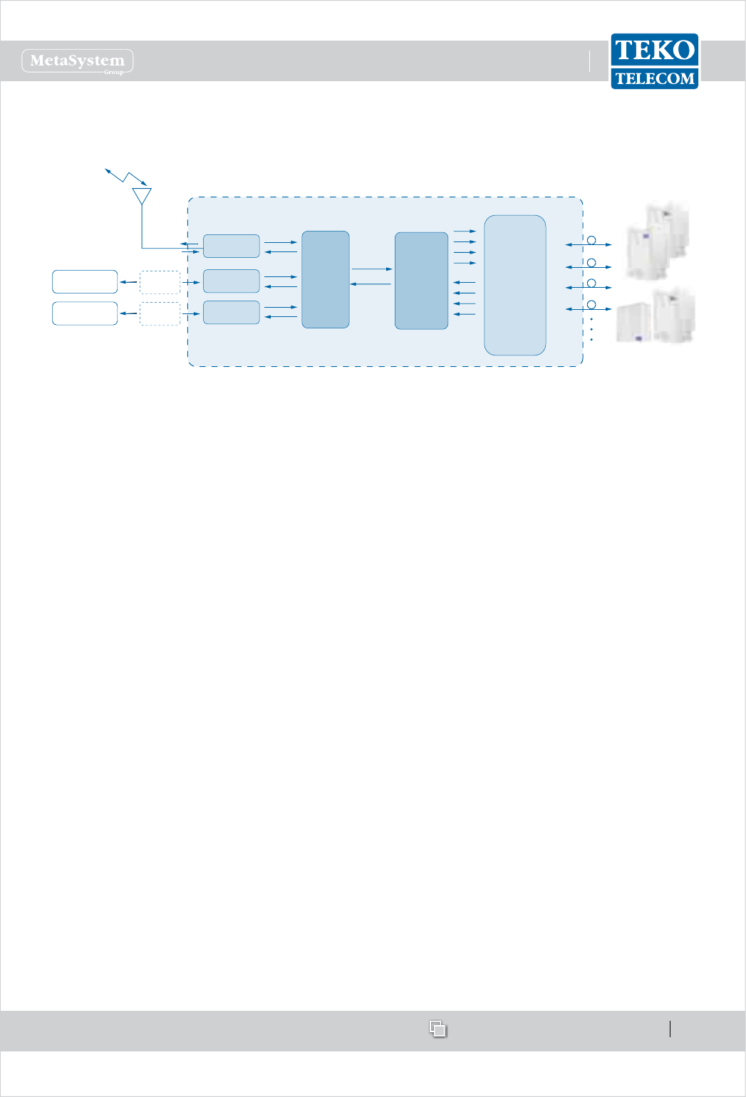
www.tekotelecom.it
www.tekotelecom.it
SIRIUS: Teko Telecom Modular Coverage and Capacity System
Let us repeat !
Doc ID Number 91 080 0781 - Rel. 04 page 89
english
4-WAY
SPLITTER
COMBINER
TO/FROM
REMOTE UNITS
4-WAY
SPLITTER
COMBINER USED
TO MANAGE
UP TO 4 FIBER
OPTIC MODULES
FIBER OPTIC
TRANSMITTER
RECEIVER
MODULES
BTS or Node B
BTS or Node B
POI MODULE
Band 1
FIXED
ATTENUATOR
POI MODULE
Band 1
FIXED
ATTENUATOR
TDFE MODULE
Band 1
Donor
Antenna
Multi-operator / single band Optical System block diagram - Example
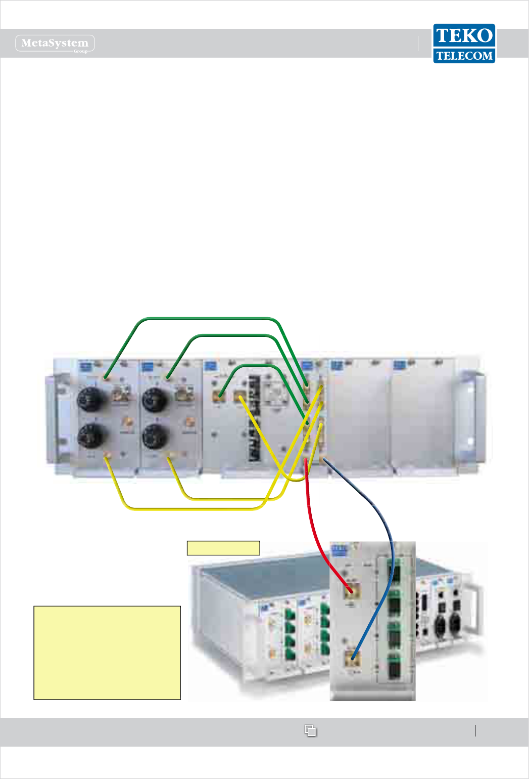
www.tekotelecom.it
www.tekotelecom.it
SIRIUS: Teko Telecom Modular Coverage and Capacity System
Let us repeat !
Doc ID Number 91 080 0781 - Rel. 04 page 90
english
Connections
Connect each POI module DL OUT connector to one of the 4-way combiner/splitter DL input
connectors (green lines).
Connect each POI module UL-IN connector to one of the 4-way combiner/splitter UL output
connectors (yellow lines).
Connect the DFE module DL connector to one of the 4-way combiner/splitter DL input
connectors (green lines).
Connect the DFE module UL connector to one of the 4-way combiner/splitter UL output
connectors (yellow lines).
Connect the 4-way combiner/splitter DL COMMON output connector to the optical subrack
DL RF input connector (red line).
Connect the 4-way combiner/splitter UL COMMON input connector to the optical subrack UL
RF output connector (blue line).
Optical Subrack
PLEASE NOTE
Each 4-way splitter/combiner
output/input connector not
connected to POI modules,
must be charged with a 50Ω
dummy load
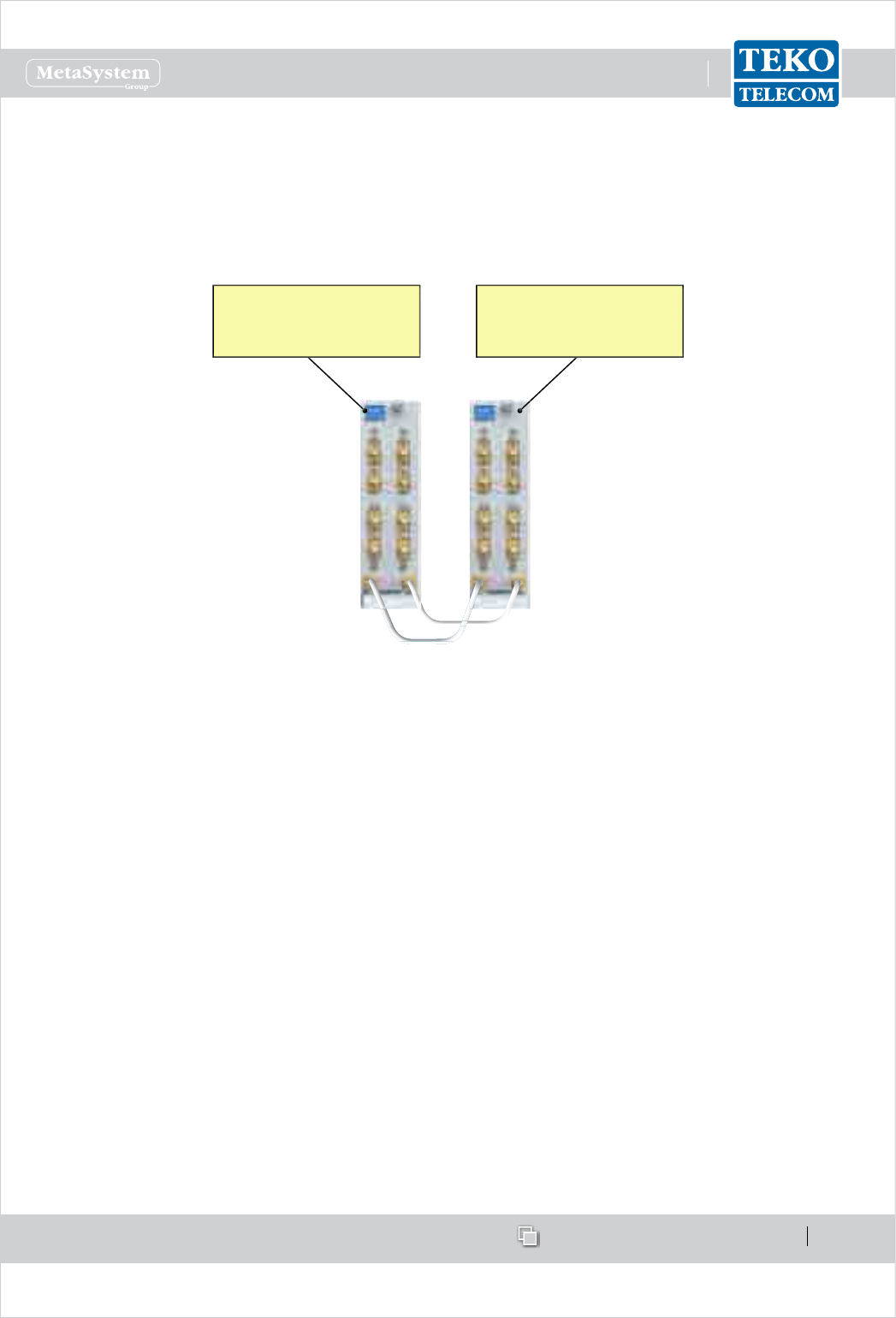
www.tekotelecom.it
www.tekotelecom.it
SIRIUS: Teko Telecom Modular Coverage and Capacity System
Let us repeat !
Doc ID Number 91 080 0781 - Rel. 04 page 91
english
Up to 4 Fiber Optic Transmitter/Receiver Modules (i.e. up to 16 Remote Units) can be managed
if another 4-way combiner/splitter module is equipped.
Connect the 4-way combiner/splitter modules UL COMMON connectors (white line).•
Connect the 4-way combiner/splitter modules DL COMMON connectors (light blue line).•
4-way splitter/combiner
used to manage up to 4
Fiber Optic Modules
4-way splitter/combiner
used to manage up to 4 RF
Interface modules
Please refer to Application A for details about the cabling when the 4-way splitter/combiner
is used to manage multiple Fiber Optic modules.