Teko Telecom Srl DFE Digital Front End User Manual
Teko Telecom Srl Digital Front End
UserManual.wiki
>
Teko Telecom Srl
>
DFE User Manual
>
User Manual
Contents
1.
Users Manual
2.
User Manual
User Manual
Navigation menu
Upload a User Manual
Namespaces
Wiki Guide
HTML
PDF
Info
Views
User Manual
Discussion / Help
Navigation
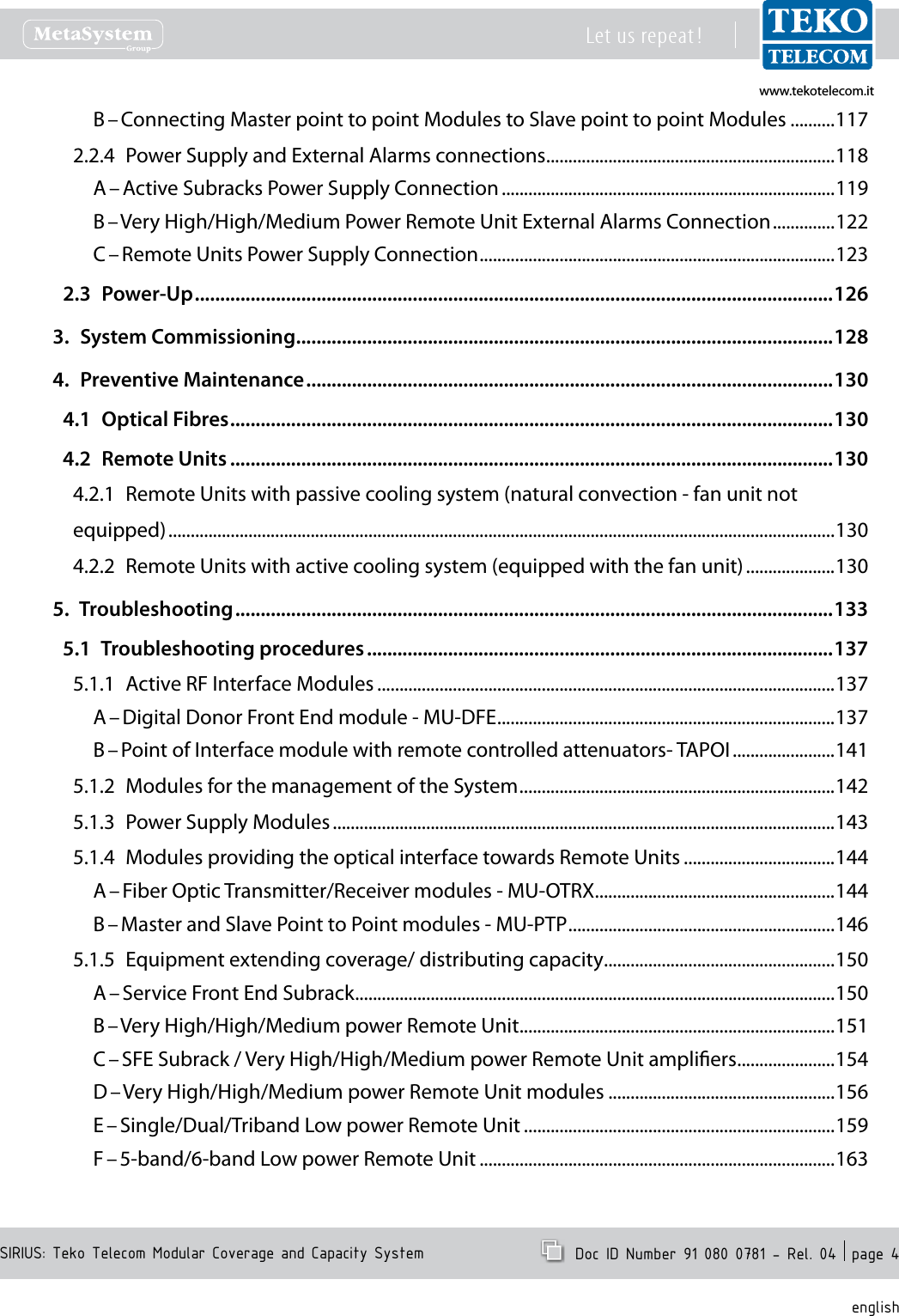
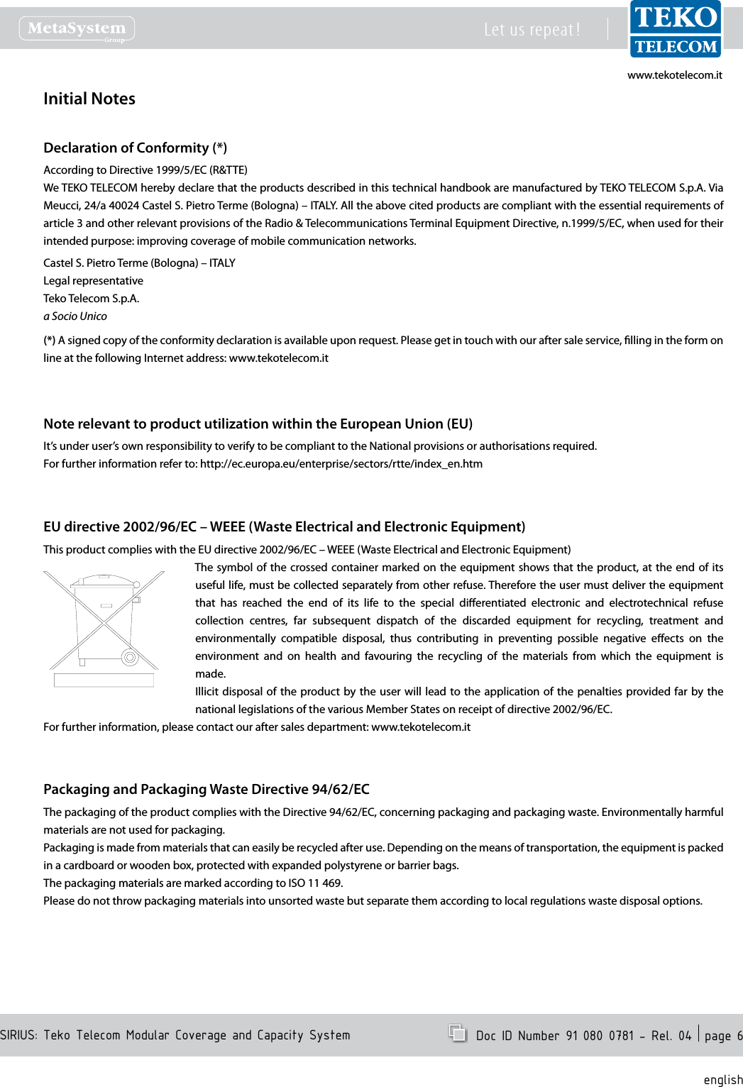
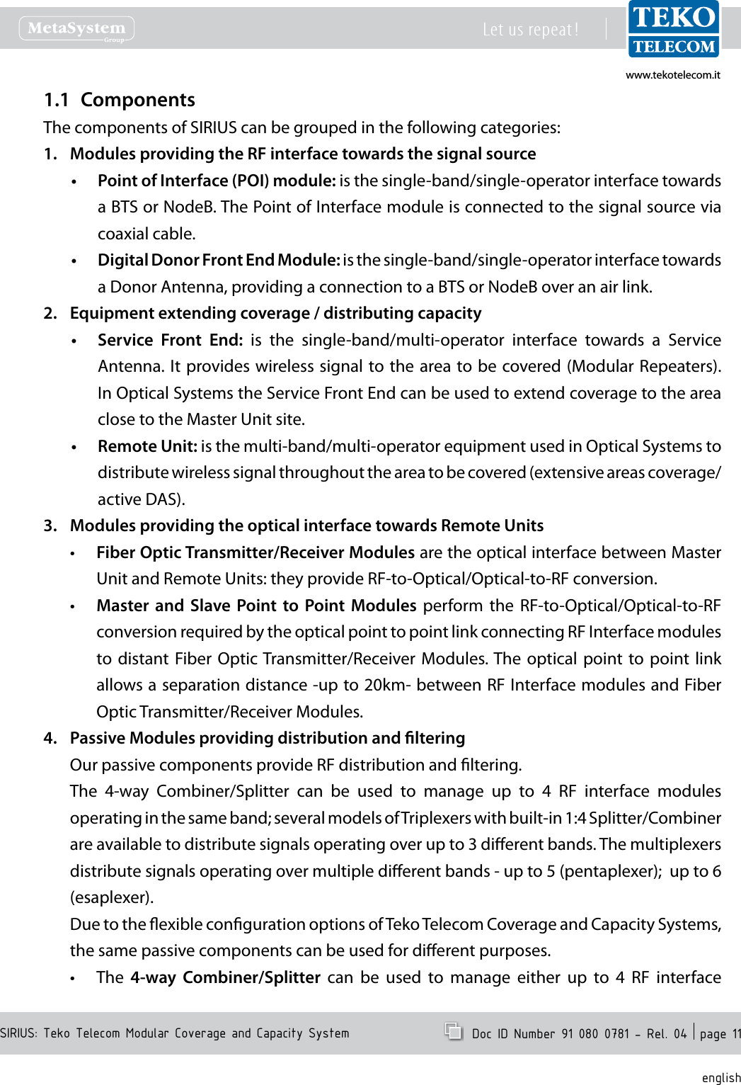
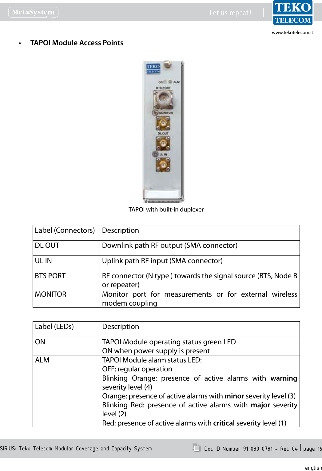
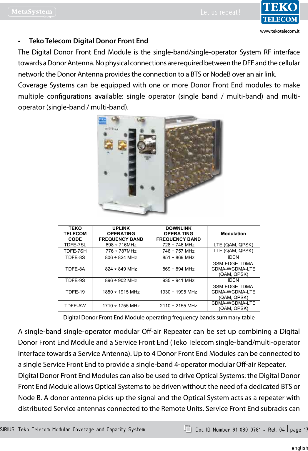
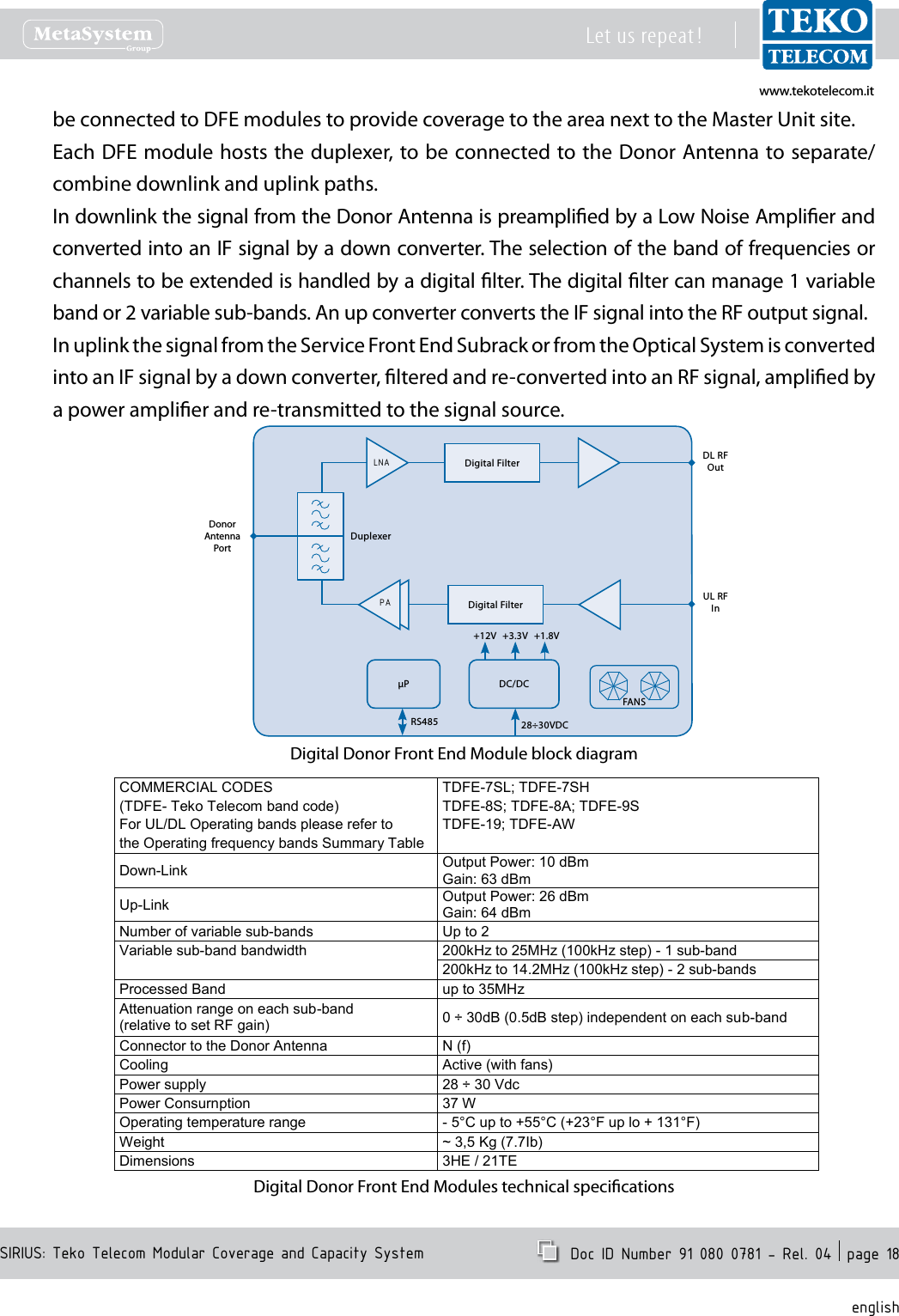
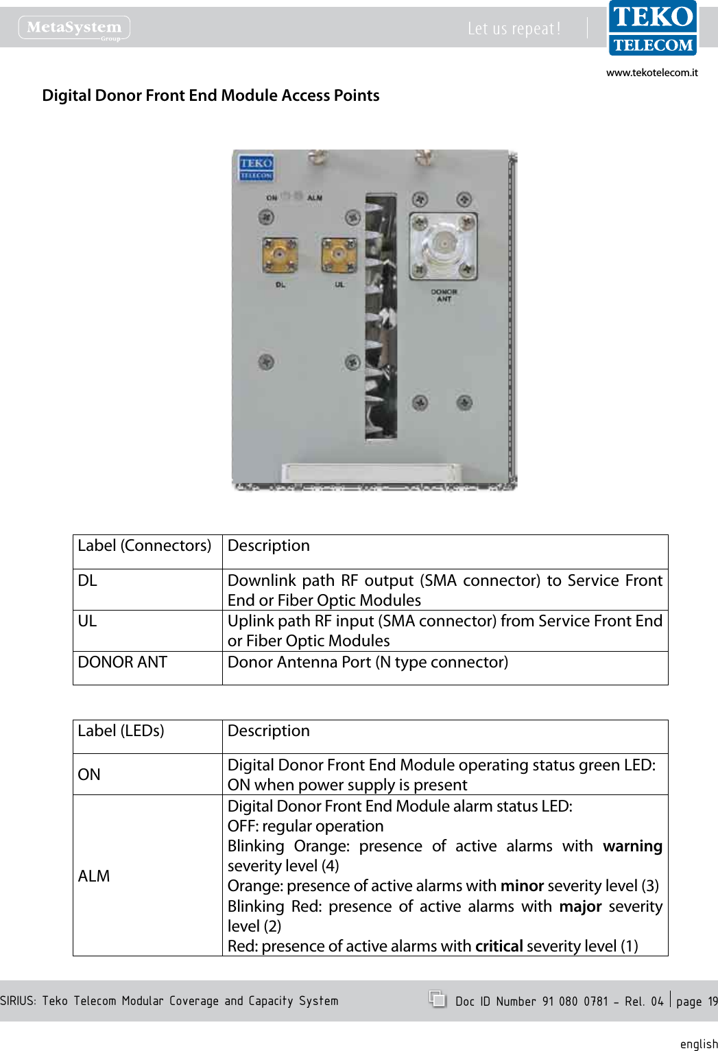
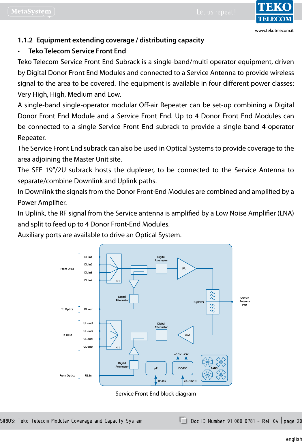
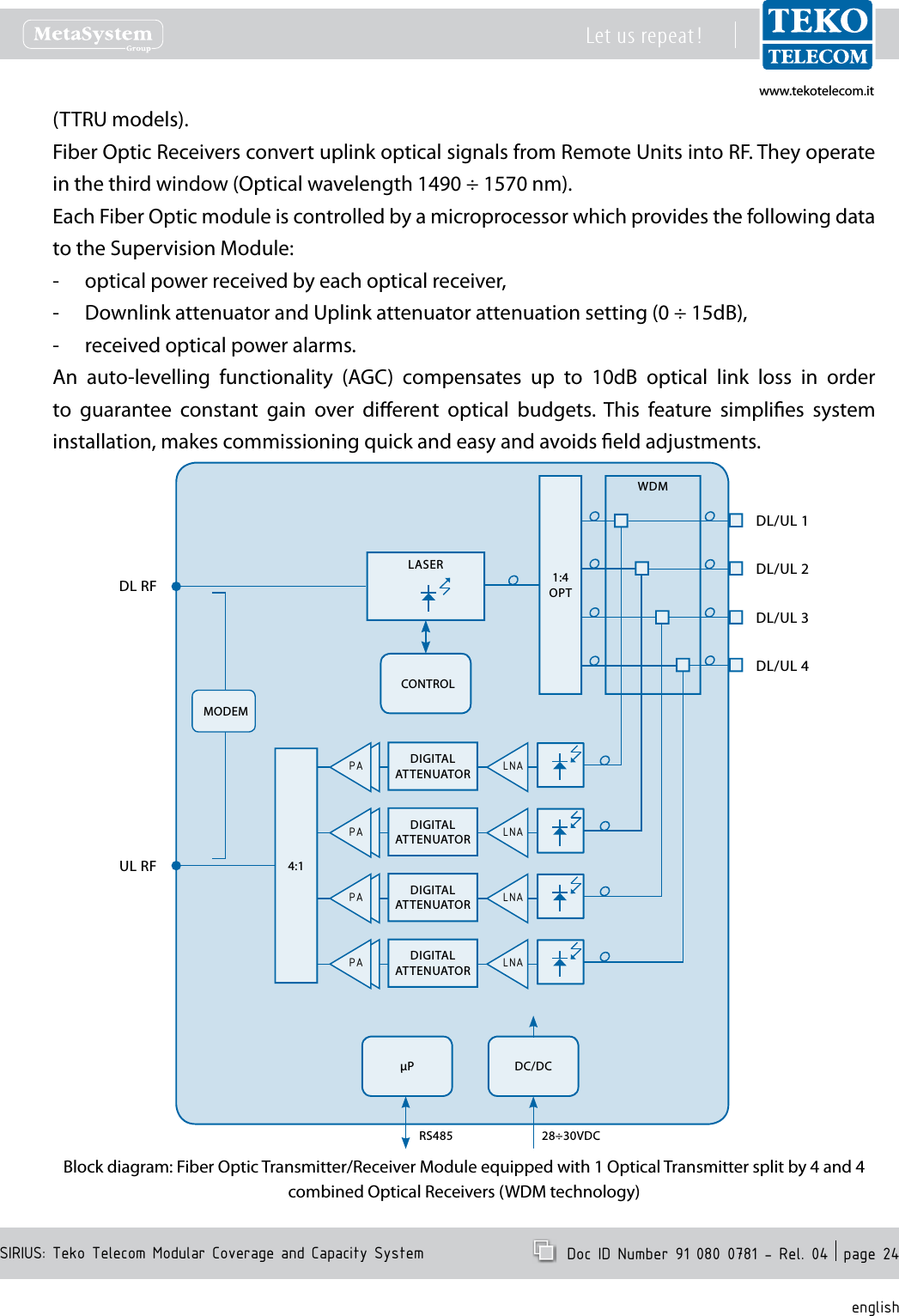
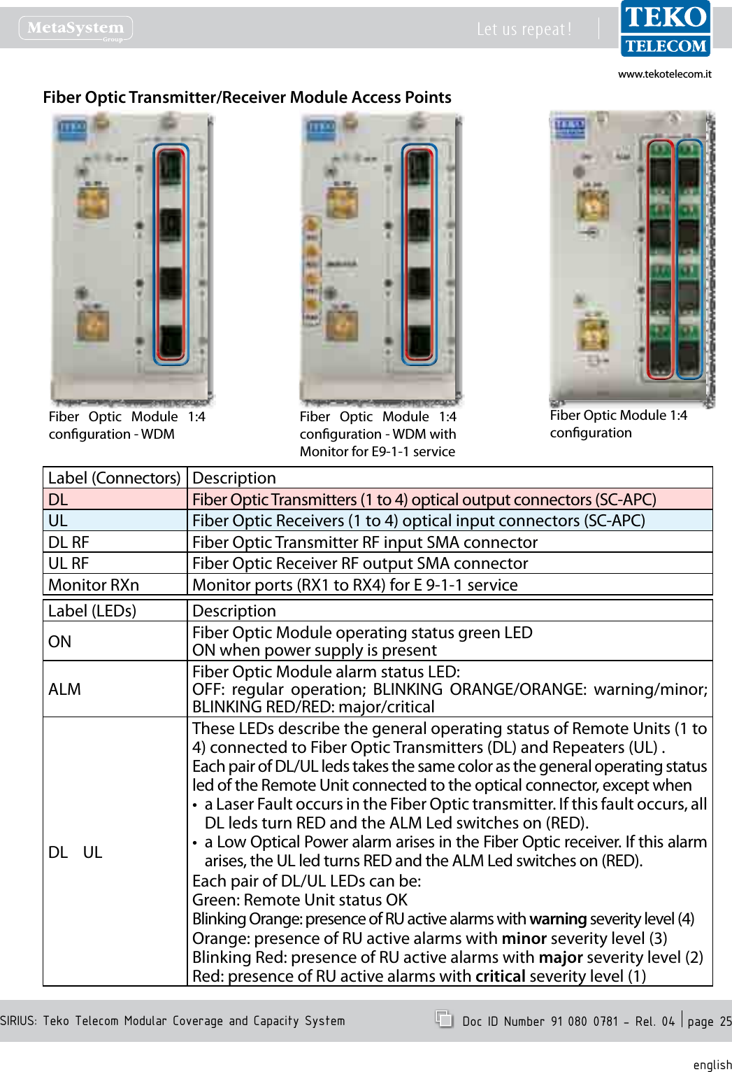
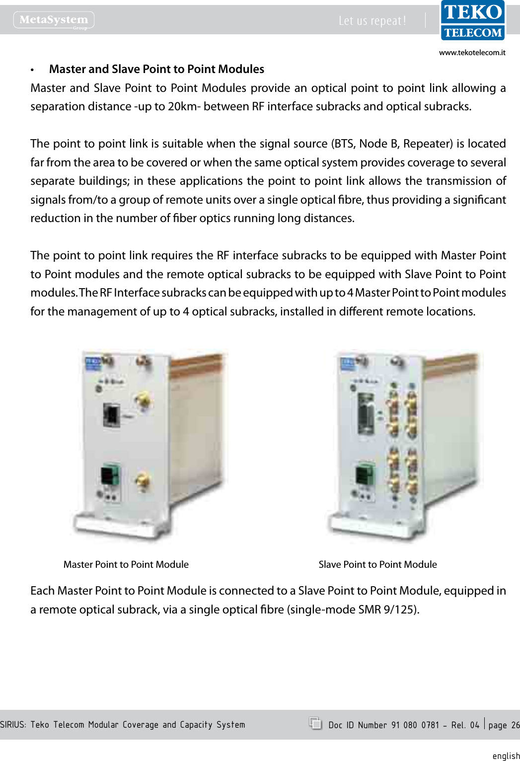
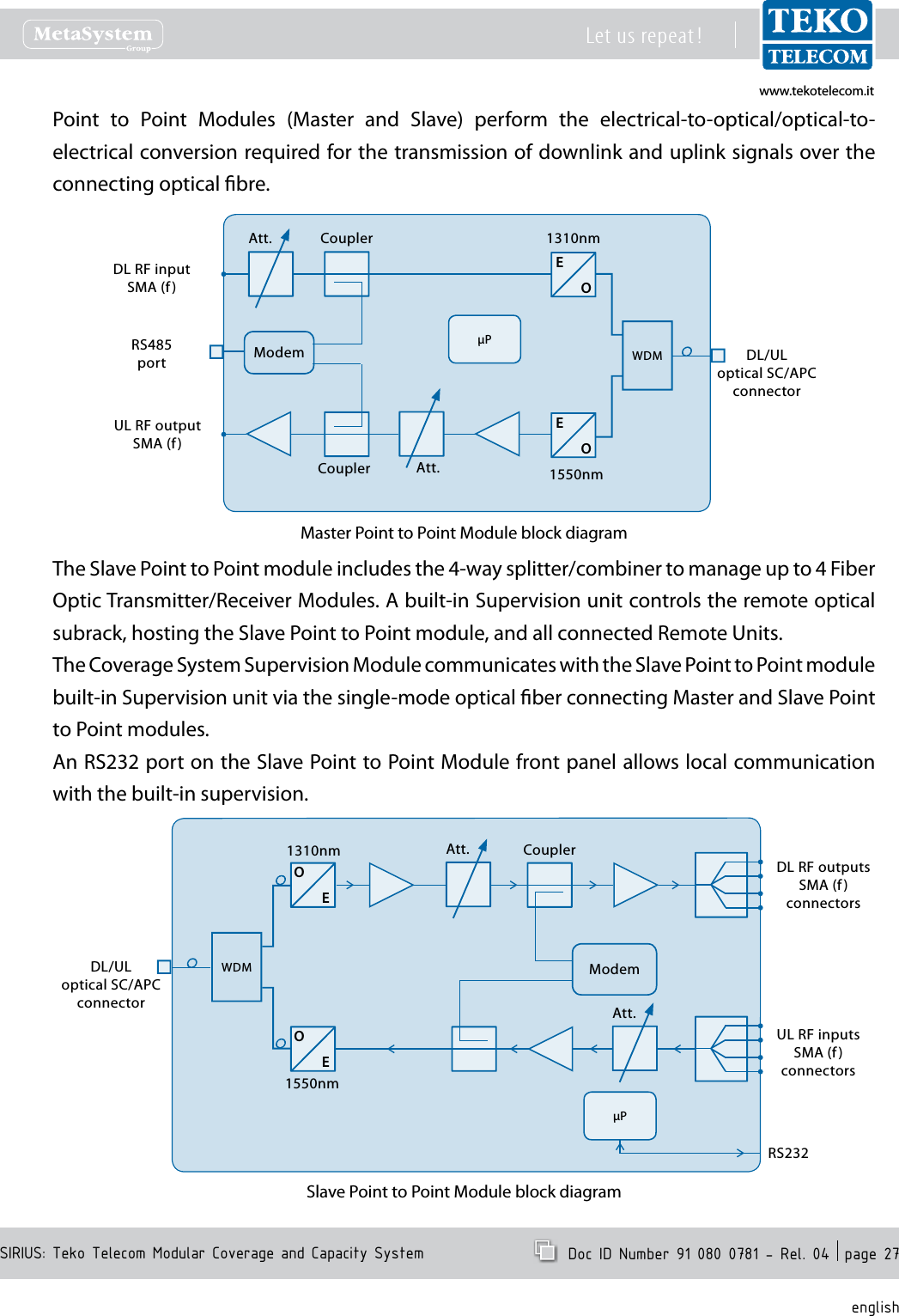
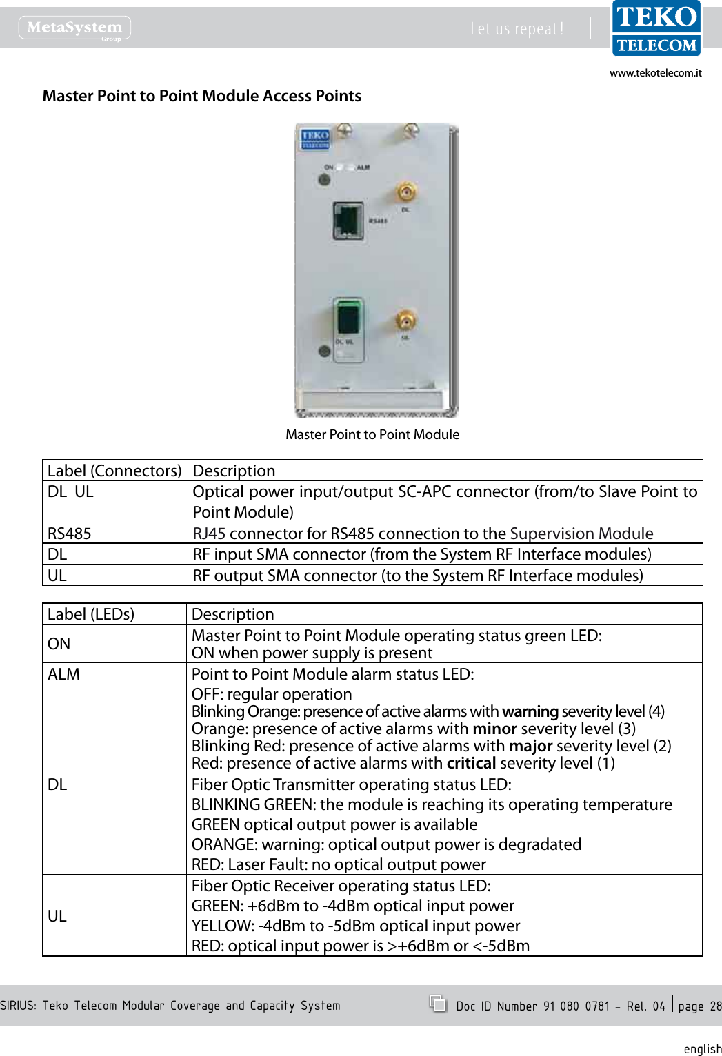
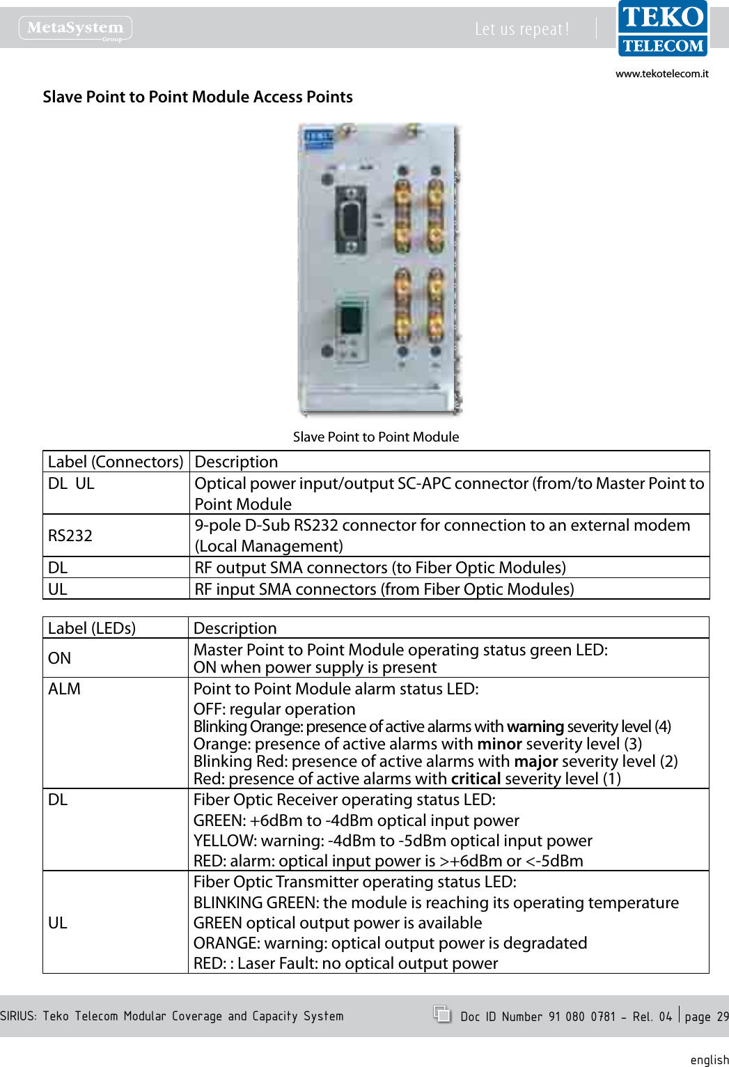
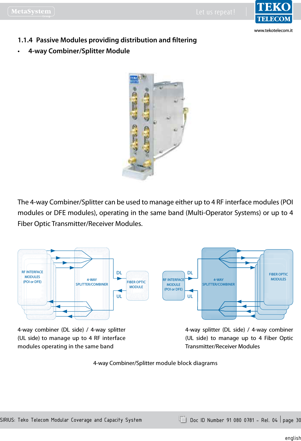
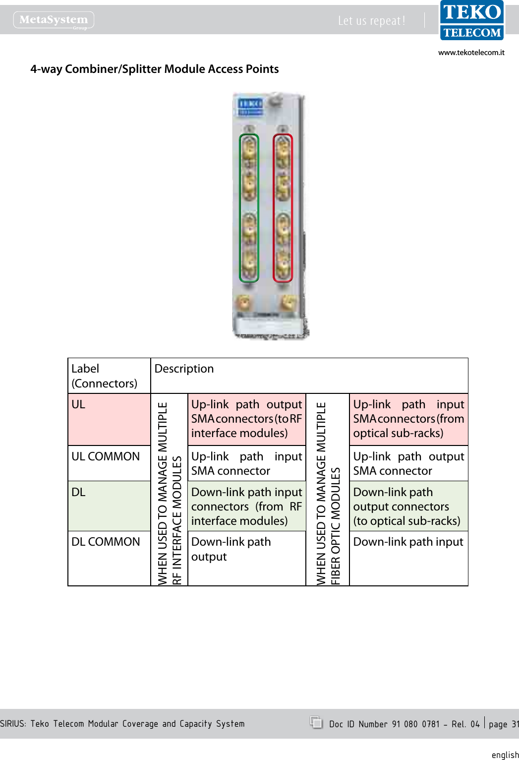
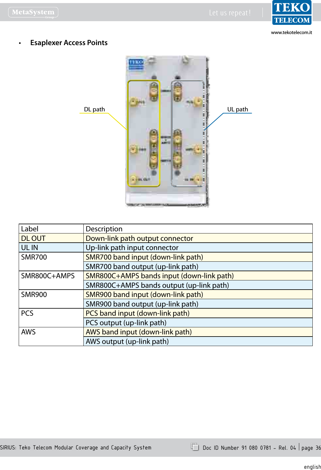
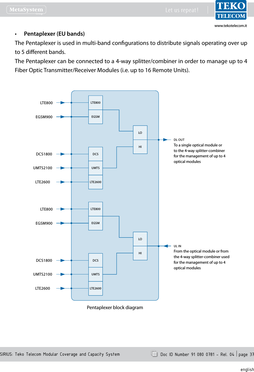
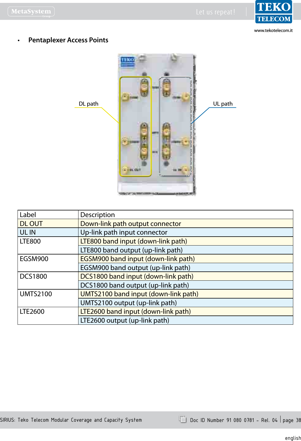
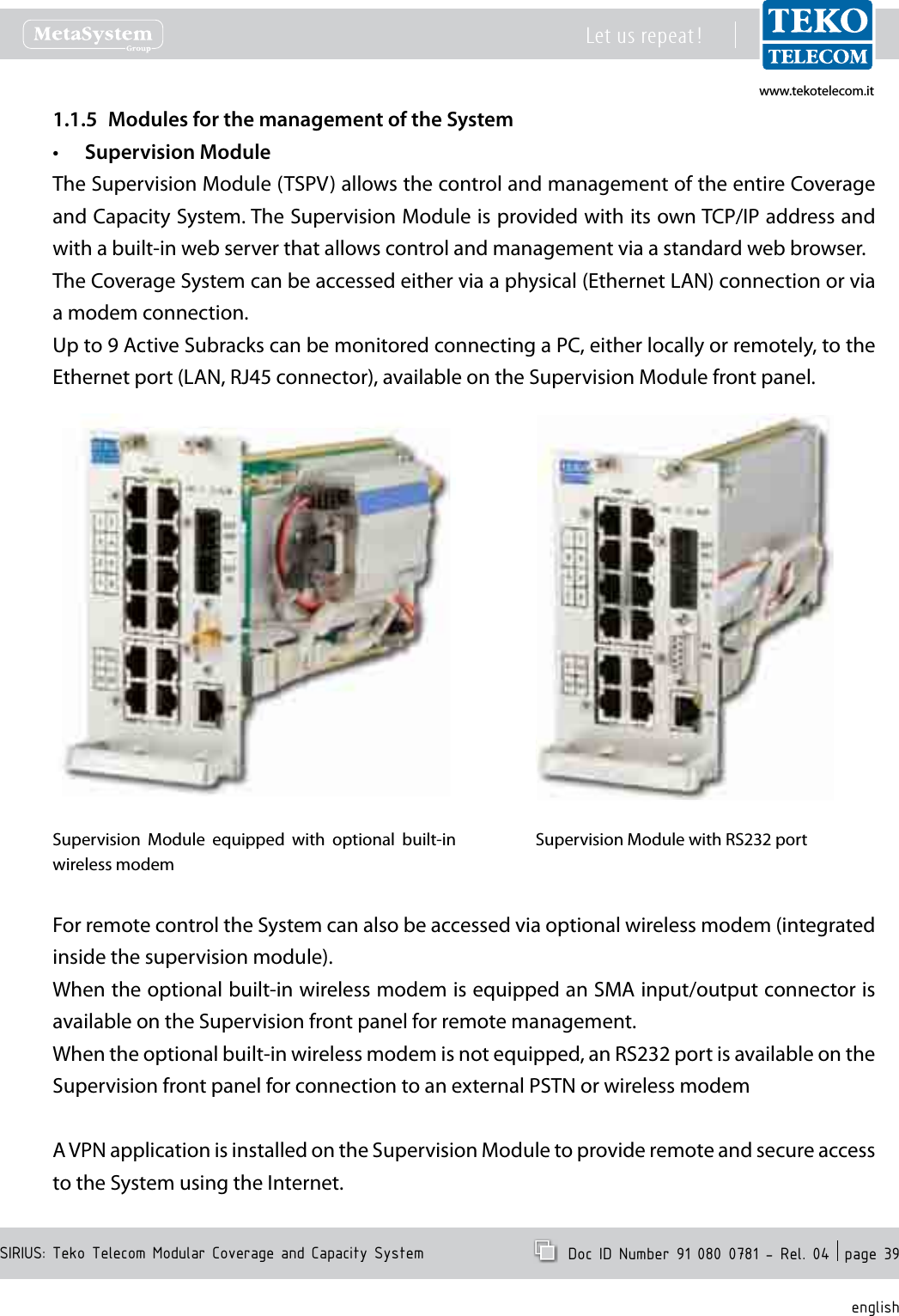
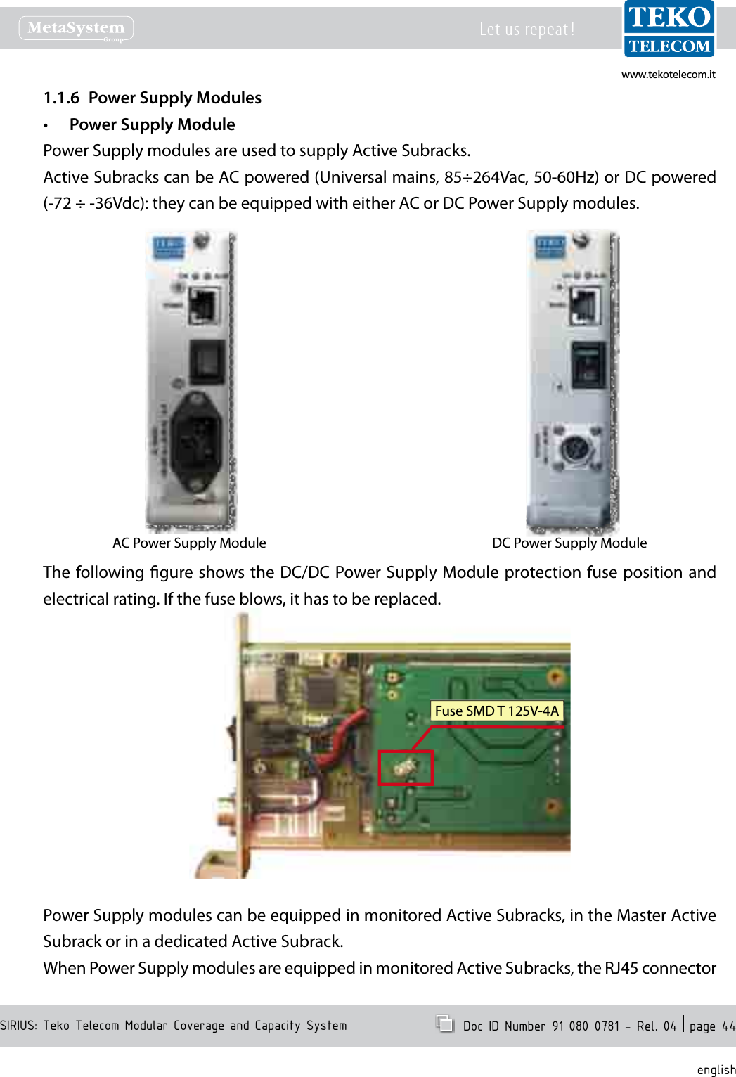
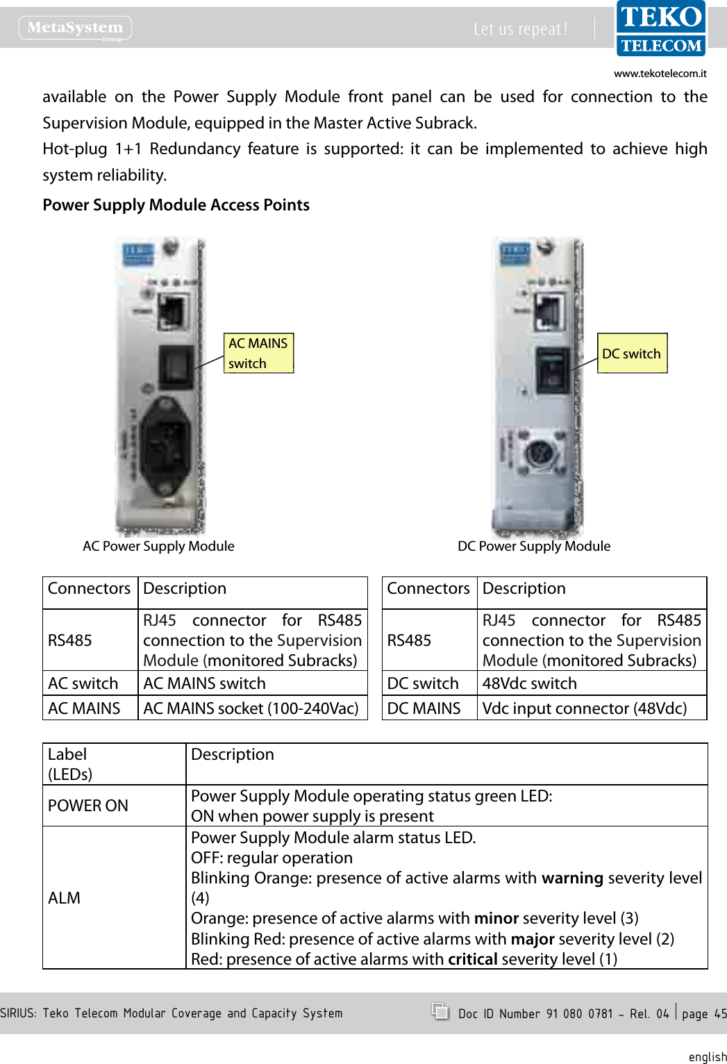
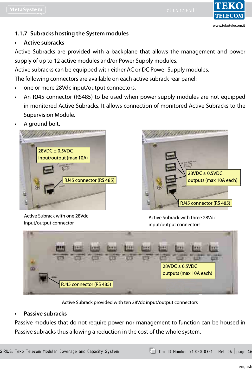
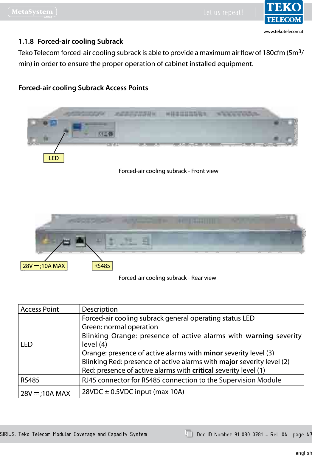
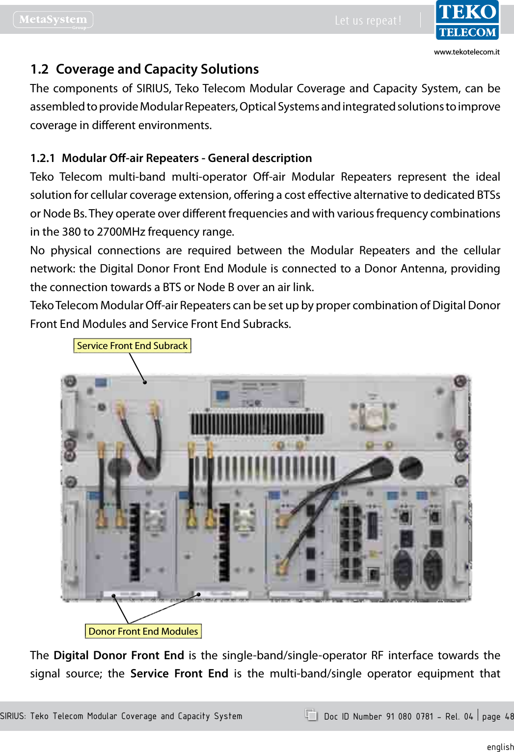
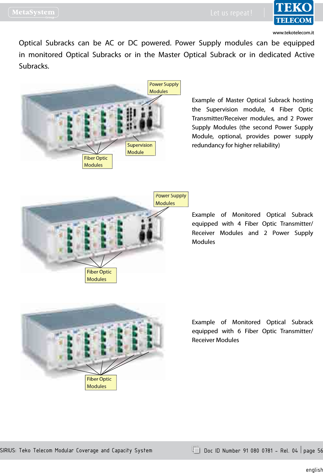
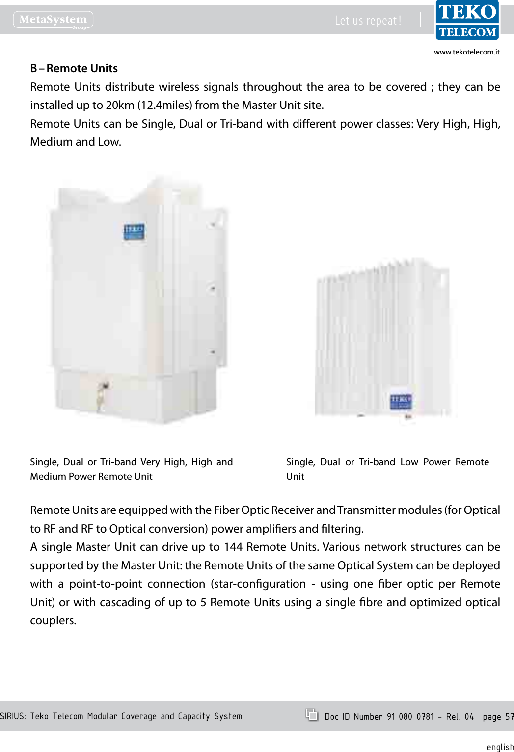
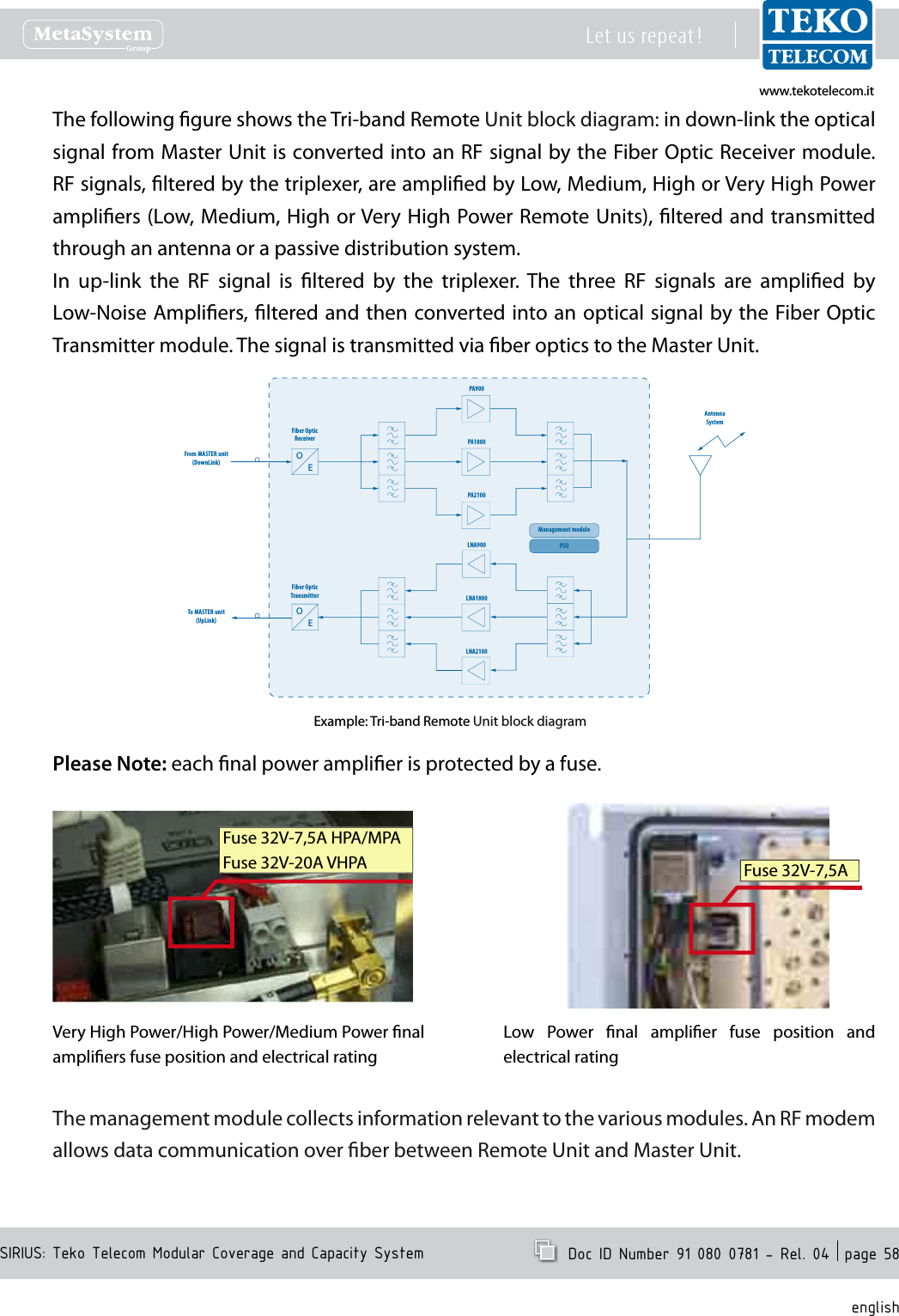
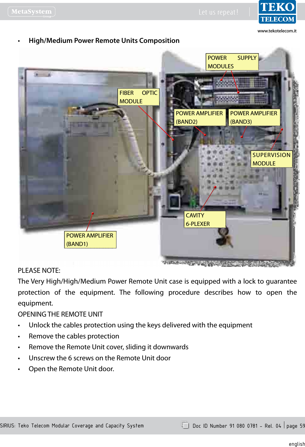
![www.tekotelecom.itwww.tekotelecom.itSIRIUS: Teko Telecom Modular Coverage and Capacity SystemLet us repeat ! Doc ID Number 91 080 0781 - Rel. 04 page 7englishCompliance with the Maximum Permissible Exposure (MPE) limits - Examples of minimum separation distance calculation, based on the EN 50385The following table summarizes the results of the calculations carried out assuming:zero losses between the output connector of Teko Telecom equipment and the input connector of the antenna•maximum gain estimated for outdoor Antenna Gi = 19dBi (for each band)•maximum gain estimated for indoor Antenna Gi = 7dBi (for each band)•no co-location or operation• in conjunction with any other antenna or transmitter. Please note The following table is not meant to represent the actual compliance distance from a particular Teko Telecom Optical System or Modular Repeater, being antennas, cables, and other RF components not provided with Teko Telecom equipment.The actual compliance distance from a particular equipment can be calculated in the nal installation phase only - when antenna, cables and other RF components specications are available.Equipment Type Maximum Output PowerMinimum separation distance between a person and the antenna in order to comply with MPE limits [m]Indoor installation Outdoor installationE=6 [V/m] E=20 [V/m] E=6 [V/m] E=20 [V/m]Remote UnitandService Front End (TSFE)Low Power Single band Remote Units•Medium Power EGSM band Remote Unit•29dBm 1.8 0.6 7.1 2.3Medium Power DCS band Remote Unit 31dBm 2.2 0.7 8.9 2.8Low Power Dual band Remote Units•Medium Power UMTS band Remote Unit•32dBm 2.5 0.8 10.1 3.2Triband Low Power Remote Units 33.8dBm 3.1 1.0 12.3 3.9Dual band Medium Power Remote Units 34.6dBm 3.4 1.1 13.4 4.2Medium Power Triband Remote Units 35.6dBm 3.8 1.5 15.2 4.8Low Power 5-band Remote Unit•High Power TETRA Remote Unit•High Power TETRA Service Front End•36dBm 4.0 1.3 15.9 5.0High Power Single band Remote Units (LTE800 •or EGSM or DCS or UMTS)High Power Service Front End (LTE800 or EGSM •or DCS or UMTS or LTE2600)40dBm 6.3 2.0 25.1 8.0High Power Single band Remote Unit (LTE2600) 41dBm 7.1 2.2 28.1 8.9High Power Dual band Remote Units (LTE800 •and/or EGSM and/or DCS and/or UMTS)Very High Power Single band Remote Units•Very High Power Service Front End (LTE800 or •EGSM or DCS or UMTS)43dBm 8.9 2.8 35.6 11.2High Power Dual Band Remote Units (LTE800 or EGSM or DCS or UMTS with LTE2600)43.5dBm 9.5 3.0 37.7 11.9High Power Tri Band Remote Units (LTE800 and/or EGSM and/or DCS and/or UMTS)44.7dBm 10.9 3.5 43.6 13.8High Power Tri Band Remote Units (LTE800 or EGSM or DCS or UMTS with LTE2600)45.1dBm 11.4 3.6 45.3 14.3Very High Power Dual Band Remote Units 46dBm 12.6 4.0 50.3 15.9Very High Power Tri Band Remote Units 47.8dBm 15.5 4.9 61.6 19.5Donor Front End(TDFE)Single Band TETRA Donor Front End 21dBm 0.7 0.2 2.8 0.9Single Band EGSM Donor Front End 23dBm 0.9 0.3 3.6 1.1Single Band DCS Donor Front End 25dBm 1.1 0.4 4.5 1.4Single Band LTE 800 or LTE2600 Donor Front End 26dBm 1.3 0.4 5.0 1.6Single Band UMTS Donor Front End 27dBm 1.4 0.5 5.6 1.8](https://usermanual.wiki/Teko-Telecom-Srl/DFE.User-Manual/User-Guide-1738161-Page-7.png)