Teko Telecom Srl LOWPOWER6 OPTICAL SYSTEMS User Manual
Teko Telecom Srl OPTICAL SYSTEMS
UserManual.wiki
>
Teko Telecom Srl
>
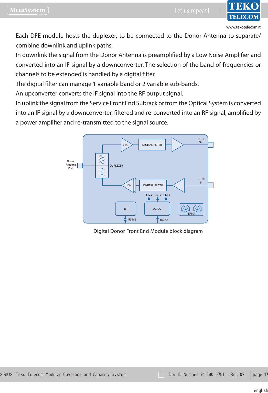
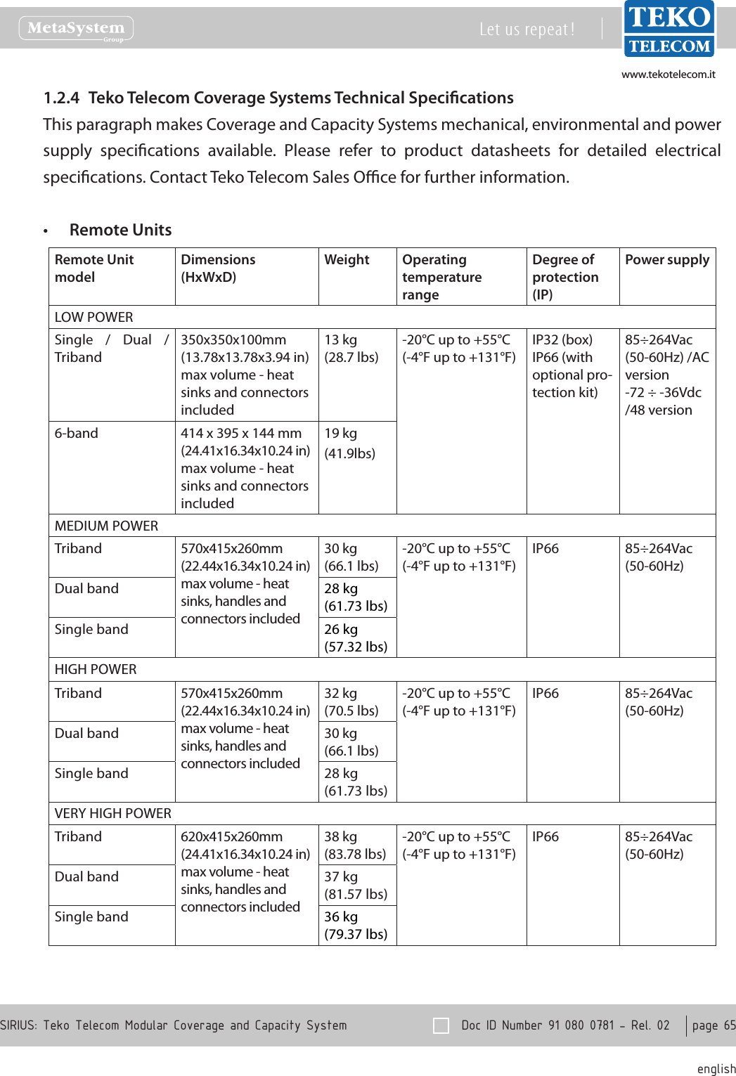
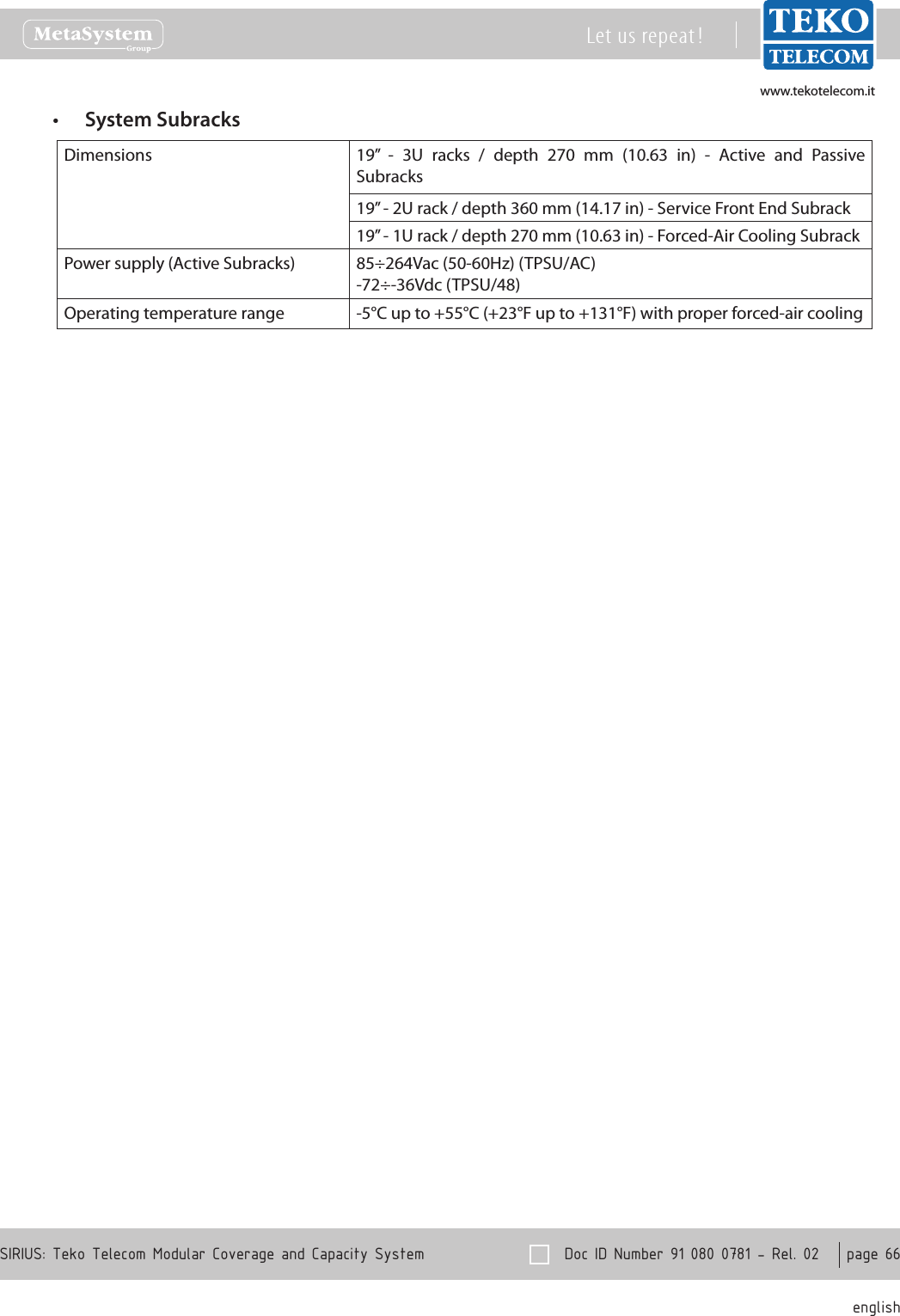
LOWPOWER6 User Manual
User Manual
Navigation menu
Upload a User Manual
Namespaces
Wiki Guide
HTML
PDF
Info
Views
User Manual
Discussion / Help
Navigation