Teko Telecom Srl VHPA25 Very High Power Amplifier User Manual
Teko Telecom Srl Very High Power Amplifier
User Manual
TECHNICAL HANDBOOK
Doc ID Number 91 080 0783 - Rev. 01
TEKO DAS Platform
TEKO DAS PLATFORM
PART A - COMPOnEnTS AnD SOLuTiOnS
BOLOGNA, 14/07/2015
UPDATINGS:
.........................................
.........................................
.........................................
.........................................
Document Identification Number
91 080 0783 - Rev. 01
TEKO DAS Platform
TEKO DAS PLATFORM
PART A - COMPOnEnTS AnD SOLuTiOnS

Teko DAS Platform Technical Handbook Doc ID Number 91 080 0783 rev. 01 | page A3
TEKO DAS Platform
Table of Contents - Part A
Initial Notes......................................................................................................................................A4
Declaration of Conformity ....................................................................................................................................... A4
Note relevant to product utilization within the European Union (EU) ..................................................... A4
EU directive 2011/65/EU – RoHS (Restriction of the use of certain Hazardous Substances) ............ A4
EU directive 2012/19/EU – WEEE (Waste Electrical and Electronic Equipment) .................................... A4
Packaging and Packaging Waste Directive 94/62/EC ...................................................................................... A4
Compliance with the Maximum Permissible Exposure (MPE) limits - Examples of minimum
separation distance calculation, based on the EN 50385 .............................................................................. A5
Industry Canada / Industrie Canada ...................................................................................................................... A7
Part A. Teko Platform Components ......................................................................................... A10
A1 Overview .............................................................................................................................. A10
A2 Components ........................................................................................................................ A12
A.2.1 Modules providing the RF interface towards the signal source ...................................................A14
A.2.2 Equipment extending coverage / distributing capacity ..................................................................A24
A.2.3 Modules providing the optical interface towards Remote Units .................................................A27
A.2.4 Passive Modules providing distribution and ltering .......................................................................A34
A.2.5 Master Unit Components for Time Division LTE (LTE-TDD) technology .....................................A43
A.2.6 Components for the management of the System .............................................................................A46
A.2.7 Power Supply Components ........................................................................................................................A51
A.2.8 Subracks hosting the System modules ..................................................................................................A60
A.2.9 Forced-air cooling Subrack .........................................................................................................................A62
A3 Coverage and Capacity Solutions ................................................................................... A64
A.3.1 Rack-mounted Modular Repeater............................................................................................................A64
A.3.2 Optical DAS ......................................................................................................................................................A66
A.3.3 Coverage Systems Management and Power Supply ........................................................................A79
A.3.4 Coverage Systems Technical Specications .........................................................................................A83
Part B. Teko DAS Platform Installation Maintenance Troubleshooting
Part C. Safety Rules (Règles de sécurité) and Standards
Warnings and caution statements
Mises en garde et déclarations de précaution
A
B
C
Components & Solutions
Teko DAS Platform Technical Handbook Doc ID Number 91 080 0783 rev. 01 | page A4
TEKO DAS Platform
Initial Notes
Declaration of Conformity
According to Directive 1999/5/EC (R&TTE)
We TEKO TELECOM S.r.l., member of JMA Wireless Group, hereby declare that the products described in this technical handbook are compliant
with the essential requirements of article 3 and other relevant provisions of the Radio & Telecommunications Terminal Equipment Directive,
n.1999/5/EC, when used for their intended purpose: improving coverage of mobile communication networks.
Castel S. Pietro Terme (Bologna) – ITALY
Legal representative
Teko Telecom S.r.l.
a Socio Unico
(*) A signed copy of the conformity declaration is available upon request. For further information, please contact our after sales department:
www.jmawireless.com
Note relevant to product utilization within the European Union (EU)
It’s under user’s own responsibility to verify to be compliant to the National provisions or authorisations required.
For further information refer to: http://ec.europa.eu/enterprise/sectors/rtte/index_en.htm
EU directive 2011/65/EU – RoHS (Restriction of the use of certain Hazardous Substances)
This product complies with EU Directive 2011/65/EC on Restriction of the use of certain Hazardous Substances in electrical and electronic
equipment (also known as “RoHS Recast” or “RoHS 2”). The product does not contain the substances listed in the Directive in concentrations
higher than the maximum admitted values.
The Environmental Friendly Use Period (EFUP) for all enclosed products and their parts are per the symbol shown here, unless
otherwise marked. Certain parts may have a dierent EFUP (for example, battery modules) and so are marked to reect such.
The Environmental Friendly Use Period is valid only when the product is operated under the conditions dened in the
product manual.
EU directive 2012/19/EU – WEEE (Waste Electrical and Electronic Equipment)
This product complies with the EU directive 2012/19/EU – WEEE (Waste Electrical and Electronic Equipment)
The symbol of the crossed container marked on the equipment shows that the product, at the end of its
useful life, must be collected separately from other refuse. Therefore the user must deliver the equipment
that has reached the end of its life to the special dierentiated electronic and electrotechnical refuse
collection centres, far subsequent dispatch of the discarded equipment for recycling, treatment and
environmentally compatible disposal, thus contributing in preventing possible negative eects on the
environment and on health and favouring the recycling of the materials from which the equipment is
made.
Illicit disposal of the product by the user will lead to the application of the penalties provided far by the
national legislations of the various Member States on receipt of directive 2012/19/EU.
For further information, please contact our after sales department: www.jmawireless.com
Packaging and Packaging Waste Directive 94/62/EC
The packaging of the product complies with the Directive 94/62/EC, concerning packaging and packaging waste. Environmentally harmful
materials are not used for packaging.
Packaging is made from materials that can easily be recycled after use. Depending on the means of transportation, the equipment is packed
in a cardboard or wooden box, protected with expanded polystyrene or barrier bags.
The packaging materials are marked according to ISO 11 469.
Please do not throw packaging materials into unsorted waste but separate them according to local regulations waste disposal options.
(*)
A
B
C
Components & Solutions

Teko DAS Platform Technical Handbook Doc ID Number 91 080 0783 rev. 01 | page A5
TEKO DAS Platform
Compliance with the Maximum Permissible Exposure (MPE) limits - Examples of minimum separation
distance calculation, based on the EN 50385
The following table summarizes the results of the calculations carried out assuming:
zero losses between the output connector of Teko equipment and the input connector of the antenna•
maximum gain estimated for outdoor Antenna Gi = 19dBi (for each band)•
maximum gain estimated for indoor Antenna Gi = 7dBi (for each band)•
no co-location or operation• in conjunction with any other antenna or transmitter.
Please note
The following table is not meant to represent the actual compliance distance from a particular Teko Optical System or Modular Repeater,
being antennas, cables, and other RF components not provided with Teko equipment.
The actual compliance distance from a particular equipment can be calculated in the nal installation phase only - when antenna, cables and
other RF components specications are available.
Equipment Type Maximum
Output
Power
(dBm)
Minimum separation distance between a person and
the antenna in order to comply with MPE limits [m]
Indoor installation Outdoor installation
E=6 [V/m] E=20 [V/m] E=6 [V/m] E=20 [V/m]
Remote Unit
and
Service Front
End (TSFE)
Low Power Single band Remote Units•
Medium Power EGSM band Remote Unit• 29 1.8 0.6 7.1 2.3
Medium Power DCS band Remote Unit 31 2.2 0.7 8.9 2.8
Low Power Dual band Remote Units•
Medium Power UMTS band Remote Unit• 32 2.5 0.8 10.1 3.2
Triband Low Power Remote Units 33.8 3.1 1.0 12.3 3.9
Dual band Medium Power Remote Units 34.6 3.4 1.1 13.4 4.2
Low Power 4-band Remote Units 35 3.6 1.1 14.2 4.5
Medium Power Triband Remote Units 35.6 3.8 1.5 15.2 4.8
Low Power 5-band Remote Units•
High Power TETRA Remote Unit•
High Power TETRA Service Front End•
36 4.0 1.3 15.9 5.0
High Power Single band Remote Units (LTE800 or •
EGSM or DCS or UMTS)
High Power Service Front End (LTE800 or EGSM or •
DCS or UMTS or LTE2600)
40 6.3 2.0 25.1 8.0
High Power Single band Remote Unit (LTE2600) 41 7.1 2.2 28.1 8.9
High Power Dual band Remote Units (LTE800 •
and/or EGSM and/or DCS and/or UMTS)
Very High Power Single band Remote Units•
Very High Power Service Front End (LTE800 or •
EGSM or DCS or UMTS)
43 8.9 2.8 35.6 11.2
High Power Dual Band Remote Units (LTE800 or
EGSM or DCS or UMTS with LTE2600) 43.5 9.5 3.0 37.7 11.9
High Power Triband Remote Units (LTE800 and/or
EGSM and/or DCS and/or UMTS) 44.7 10.9 3.5 43.6 13.8
High Power Tri Band Remote Units (LTE800 or EGSM
or DCS or UMTS with LTE2600) 45.1 11.4 3.6 45.3 14.3
Very High Power Dual Band Remote Units
Very Very High Power (40W) Single band Remote Units 46 12.6 4.0 50.3 15.9
Very High Power 4-Band Remote Unit
Very Very High Power (40W) Dual band Remote Units 49 17.9 5.7 71.1 22.5
Very High Power Triband Remote Units 47.8 15.5 4.9 61.6 19.5
Very Very High Power (40W) Triband Remote Units 50 20 6.3 79.5 25.1
Very Very High Power (40W) 4-band Remote Units 52 21.9 6.9 87.1 27.5
Donor Front
End
(TDFE)
Single Band TETRA Donor Front End 21 0.7 0.2 2.8 0.9
Single Band EGSM Donor Front End 23 0.9 0.3 3.6 1.1
Single Band DCS Donor Front End 25 1.1 0.4 4.5 1.4
Single Band LTE 800 or LTE2600 Donor Front End 26 1.3 0.4 5.0 1.6
Single Band UMTS Donor Front End 27 1.4 0.5 5.6 1.8
A
B
C
Components & Solutions
Teko DAS Platform Technical Handbook Doc ID Number 91 080 0783 rev. 01 | page A6
TEKO DAS Platform
Operation is subject to the following conditions: (1) this device may not cause interference, and (2) this device must
accept any interference, including interference that may cause undesired operation of the device.
Changes or modications not expressly approved by the party responsible for compliance could void the user’s
authority to operate the equipment.
The antenna(s) used for this transmitter must be installed to provide a separation distance of:
at least 50cm for Low Power Remote Units family in Tri-Band system (with 8dB of maximum antenna gain for operating bands lower than •
1.5GHz and 11dB for operating bands higher than 1.5GHz),
at least 50cm for Low Power Remote Units family in Six-Band system (with 4.5dB of maximum antenna gain for operating bands lower than •
1.5GHz and 6.5dB for operating bands higher than 1.5GHz),
at least 50cm for Enhanced Power Remote Units family in Dual Band Public Safety system (with 7.89dB of maximum antenna gain for •
operating bands lower than 1.5GHz),
at least 100cm for up to Six-Band Enhanced Power Remote Units family (with 16dB of maximum antenna gain for operating bands lower •
than 1.5GHz and 20dB for operating bands higher than 1.5GHz),
at least 50cm for Donor Front End family (with 12.84dB of maximum antenna gain for operating bands lower than 1.5GHz and 19dB for •
operating bands higher than 1.5GHz),
at least 150cm for Very High Power Amplier radio module, equipped inside Service Front End family and Very High Power/Pole-mounting •
Remote Units family (with 8dB of maximum antenna gain for operating bands lower than 1.5GHz and 11.5dB for operating bands higher
than 1.5GHz)
at least 150cm for Very Very High Power Amplier radio module, equipped inside Service Front End family and Very Very High Power (40W)/•
Pole-mounting Remote Units family (with 5.4dB of maximum antenna gain for operating bands lower than 1.5GHz and 8.5dB for operating
bands higher than 1.5GHz)
from all persons assuming no co-location or operating in conjunction with any other antenna or transmitter.
Specications of antennas, cables, RF components, etc will be provided only in the nal installation phase, being the external antenna not
provided with equipment.
Equipment will be accessible only to maintenance men, that must switch it o before any maintenance operation.
WARNING FOR COMMERCIAL BANDS:
SMR700 Low (DL 728 ÷ 746MHz, UL 698 ÷ 716MHz)
SMR700 High (DL 746 ÷ 756MHz, UL 777 ÷ 787 MHz)
Commercial SMR800 (DL 862 ÷ 869MHz, UL 817 ÷ 824MHz)
AMPS (DL 869 ÷ 894MHz, UL 824 ÷ 849MHz)
SMR900 (DL 935 ÷ 940MHz, UL 896 ÷ 901MHz)
NBPCS (DL 940 ÷ 941MHz, UL 901 ÷ 902MHz)
PCS (DL 1930 ÷ 1995MHz, UL 1850 ÷ 1915MHz)
AWS (HBlock) (DL 1995 ÷ 2000MHz, UL 1915 ÷ 1920MHz)
AWS (DL 2110 ÷ 2155MHz, UL 1710 ÷ 1755MHz)
AWSE (DL 2110 ÷ 2180MHz, UL 1710 ÷ 1780MHz)
WCS (DL 2350 ÷ 2360MHz, UL 2305 ÷ 2315MHz)
2500 (LTE-TDD DL/UL 2496 ÷ 2690MHz)
WARNING FOR PUBLIC SAFETY BANDS:
Public Safety 700 (DL 763 ÷ 775MHz, UL 793 ÷ 805MHz)
Public Safety 800 (DL 851 ÷ 862MHz, UL 806 ÷ 817MHz)
Public Safety 900 (DL 935 ÷ 940MHz, UL 896 ÷ 901MHz)
Please note
Fixed stations operating in the 1710-1755MHz band are limited to 1W EIRP and to a maximum antenna height of 10meters above ground•
Regarding to Public Safety bands, to be compliant with 90.217 d)7), signal booster passbands are limited to the service band or bands •
for which the operator is authorized. In general, signal boosters should utilize the minimum passband that is sucient to accomplish
the purpose. When booster encompasses both commercial bands and public safety bands (SMR800/SMR900) has to be installed in DAS
(Distributed Antenna system) indoor system.
Regarding to Public Safety Bands, the output power capability of the Public Safety signal booster is designed for deployments providing •
a radiated power not exceeding 5W ERP for each retransmitted channel.
An example for Low/Enhanced Power, Very/Very Very High Power Amplier and Donor Front End nal installation is provided:
maximum radiated power: 5W ERP = 8.2W EIRP = 39dBm
For remote with splitter and more than one antenna:
G + Pout+ A - 10logN ≤ 39 ⇒ G ≤ 39 - (Pout+A-10logN)
with G = max gain (dBi), Pout = max signal booster output power (dBm), A = attenuation (dB), N = number of carriers
for Very High Power Amplier we suppose an attenuation (due to cable insertion, splitter, etc.) of 12dB.
A
B
C
Components & Solutions

Teko DAS Platform Technical Handbook Doc ID Number 91 080 0783 rev. 01 | page A7
TEKO DAS Platform
Industry Canada / Industrie Canada
The Radio Standards Specication 102 (RSS-102) sets out the requirements and measurement techniques used to evaluate RF exposure
compliance of radiocommunication apparatus designed to be used within the vicinity of the human body.
It is the responsibility of proponents and operators of antenna system installations to ensure that all radiocommunication and broadcasting
installations comply at all times with Health Canada’s Safety Code 6.
The antenna(s) used for this transmitter must be installed to provide a separation distance of:
at least 50cm for Enhanced Power Remote Units family in Dual Band Public Safety system (with 11dB of maximum antenna gain for •
operating bands lower than 1.5GHz),
at least 100cm for Enhanced Power Remote Units family in Six-Band system (including LTE2600 band): with 16dB of maximum antenna •
gain for operating bands lower than 1.5GHz and 20dB for operating bands higher than 1.5GHz,
at least 100cm for Enhanced Power Remote Units family in Six-Band system (including WCS2300 band): with 13,7dB of maximum antenna •
gain for SMR700 band (lower frequency) and 17,2dB of maximum antenna gain for WCS2300 band (higher frequency),
at least 50cm for Donor Front End family (with 15.5dB of maximum antenna gain for operating bands lower than 1.5GHz and 19dB for •
operating bands higher than 1.5GHz),
at least 150cm for Very High Power Amplier radio module, equipped inside Service Front End family and Very High Power/Pole-mounting •
Remote Units family (with 8dB of maximum antenna gain for operating bands lower than 1.5GHz and 11.5dB for operating bands higher
than 1.5GHz)
from all persons assuming no co-location or operating in conjunction with any other antenna or transmitter.
Specications of antennas, cables, RF components, etc will be provided only in the nal installation phase, being the external antenna not
provided with equipment.
Equipment will be accessible only to maintenance men, that must switch it o before any maintenance operation.
La spécication sur les normes radioélectriques 102 (RSS-102) énonce les exigences et les techniques de mesure utilisées pour évaluer la conformité
de l’exposition aux radiofréquences des appareils de radiocommunication conçus pour être utilisés à proximité du corps humain.
Il incombe aux promoteurs et exploitants d’installations de systèmes d’antennes de s’assurer que toutes les installations de radiocommunication et
de radiodiusion respectent tout le temps au code de sécurité 6 de santé du Canada.
La/les antenne (s) utilisée(s) pour ce transmetteur doit être installé an de fournir une distance de séparation de:
Au moins 50 cm pour la famille des unités à distance améliorée en puissance dans le système à double bande de sécurité publique (avec 11dB de •
gain maximal d’antenne pour les bandes de service inférieures à 1,5 GHz),
Au moins 100 cm pour la famille des unités à distance améliorée en puissance dans le système de six bandes (avec LTE2600 band): avec 16dB de •
gain maximal d’antenne pour les bandes inférieures à 1,5GHz et 20dB pour les bandes supérieures à 1,5 GHz),
Au moins 100 cm pour la famille des unités à distance améliorée en puissance dans le système de six bandes (avec WCS2300 band): avec 13,7dB •
de gain maximal d’antenne pour SMR700 band (fréquence inférieure) et 17,2dB de gain maximal d’antenne pour WCS2300 band (fréquence
supérieure )
Au moins 50 cm pour la famille de Front End Donateur (avec 15,5 dB de gain maximal d’antenne pour les bandes inférieures à 1,5 GHz et 19 dB •
pour les bandes supérieures à 1,5 GHz),
Au moins 150 cm pour le module amplicateur radio à très haute puissance, équipé à l’intérieur de la famille de Front End de Service et la famille •
des unités à distance à très haute puissance/support de poteau (avec 8 dB of gain maximal pour les bandes inférieures à 1,5 GHz et 11 dB pour
les bandes supérieures à 1,5 GHz)
de toutes les personnes en supposant l’absence de colocalisation ou d’exploitation en conjonction avec une autre antenne ou émetteur.
Spécications des antennes, câbles, composants à radiofréquence, etc. ne seront fournis que dans la phase nale de l’installation, étant que
l’antenne externe n’est pas fourni avec l’équipement.
L’équipement sera accessible seulement aux hommes d’entretien, qui doit l’éteindre avant toutes les opérations de maintenance.
A
B
C
Components & Solutions

Teko DAS Platform Technical Handbook Doc ID Number 91 080 0783 rev. 01 | page A8
TEKO DAS Platform
Frequency Band
Bande de
fréquence
Nominal Passband Gain
Gain dans la bande
passante nominale
Nominal Bandwidth
Largeur de bande
nominale
Rated mean output power
(single carrier)
Puissance de sortie moyenne
nominale (porteuse unique)
Input and output
impedances
Impédances d’entrée et
de sortie
Very High Power Amplier Radio Module
728-746MHz 48dB 18MHz 43dBm (20W) 50
746-756MHz 48dB 10MHz 43dBm (20W) 50
851-869MHz 48dB 18MHz 43dBm (20W) 50
869-894MHz 48dB 25MHz 43dBm (20W) 50
1930-1995MHz 48dB 65MHz 43dBm (20W) 50
2110-2155MHz 48dB 45MHz 43dBm (20W) 50
2620-2690MHz 48dB 70MHz 43dBm (20W) 50
Digital Front End
698-716MHz 64dB 18MHz 26dBm (0.4W) 50
777-787 MHz 64dB 10MHz 26dBm (0.4W) 50
806-824MHz 64dB 18MHz 26dBm (0.4W) 50
824-849MHz 64dB 25MHz 26dBm (0.4W) 50
1850-1915MHz 64dB 65MHz 26dBm (0.4W) 50
1710-1755MHz 64dB 45MHz 26dBm (0.4W) 50
2500-2570MHz 64dB 70MHz 26dBm (0.4W) 50
798-806MHz 64dB 8MHz 26dBm (0.4W) 50
Six-band Enhanced Power Remote Unit
728-746MHz 36dB 18MHz 31dBm (1.25W) 50
746-756MHz 36dB 10MHz 31dBm (1.25W) 50
851-869MHz 36dB 18MHz 31dBm (1.25W) 50
869-894MHz 36dB 25MHz 31dBm (1.25W) 50
1930-1995MHz 36dB 65MHz 31dBm (1.25W) 50
2110-2155MHz 36dB 45MHz 31dBm (1.25W) 50
2110-2180MHz 36dB 70MHz 31dBm (1.25W) 50
2350-2360MHz 36dB 10MHz 31dBm (1.25W) 50
2620-2690MHz 36dB 70MHz 31dBm (1.25W) 50
Dual-band Public Safety Enhanced Power Remote Unit
768-776MHz 36dB 8MHz 31dBm (1.25W) 50
851-869MHz 36dB 18MHz 31dBm (1.25W) 50
The Manufacturer’s rated output power of this equipment is for single carrier operation. For situations when multiple carrier signals are present,
the rating would have to be reduced by 3.5dB, especially where the output signal is re-radiated and can cause interference to adjacent band
users. This power reduction is to be by means of input power or gain reduction and not by an attenuator at the output of the device.
La puissance de sortie nominale indiquée par le fabricant pour cet appareil concerne son fonctionnement avec porteuse unique. Pour des appareils
avec porteuses multiples, on doit réduire la valeur nominale de 3,5dB, surtout si le signal de sortie est retransmis et qu’il peut causer du brouillage
aux utilisateurs de bandes adjacentes. Une telle réduction doit porter sur la puissance d’entrée ou sur le gain, et ne doit pas se faire au moyen d’un
atténuateur raccordé à la sortie du dispositif.
Teko Platform Technical Handbook 91 080 0783
© Copyright 2015 Teko Telecom S.r.l. All rights reserved.
The content of this manual is for informational use only. Information and specications regarding the products described in this document
are subject to change without notice. The images shown in this document are for illustrative purposes only; they may dier from actual
product appearance. Teko Telecom shall not be liable for technical or editorial errors contained in this manual.
A
B
C
Components & Solutions
TEKO DAS PLATFORM
PART A - COMPOnEnTS AnD SOLuTiOnS
TEKO DAS Platform
COMPONENTS

Teko DAS Platform Technical Handbook Doc ID Number 91 080 0783 rev. 01 | page A10
TEKO DAS Platform
Teko Platform ComponentsPart A.
OverviewA1
The Teko Platform is a versatile, modular, multi-technology platform designed to oer exible
and reliable wireless coverage and capacity for both indoor and outdoor environments. Teko’s
design delivers the maximum end-user performance, supporting Time Division LTE technology
and LTE-Advanced capabilities to enable multi-path performance with the exibility to adapt
coverage and capacity in any venue on an event-by-event basis.
The DAS (Distributed Antenna System) Platform is made up of two main elements: Master
Unit and Remote Units.
Teko Master Unit
The Master Unit is a rack-based platform delivering modularity that allows congurations
for dierent needs and a future-proof design to ensure you can adapt your venue to future
technologies. The Master Unit is congured to provide both the RF interface (o-air and/or
via coaxial cable) towards the signal source (BTS, NodeB, Donor) and the optical interface
towards Remote Units. It also hosts the Supervision Module for the management of the entire
System utilizing secure browser technology that enables administration from any location.
The Master Unit can be congured utilizing Donor Front End, Active Point of Interface or DAS
Trays to provide exible options to connect to any combination of Carrier interfaces. The Teko
Platform also includes the optional Multiband Spectrum Analyzer (MSA) to allow recordable
and remote monitoring of venue performance to enable easy optimization.
Architecture
The modular sub-rack allows adaptation of deployment needs including the addition of newer
technologies within sub-racks that prepares venues to be more adaptive to venue needs
(e.g. new sectors) and to introduce newer services into the existing venues DAS. The Master
Units DAS shelf and architectural design minimizes system footprint, saving 30-70% of critical
space requirements within venues, BTS Hotels, Co-location environments. The Teko system
design allows for passive repeater or active / optical DAS congurations and the system can
be recongured as needs change.
Teko Remote Units
Remote Units (RUs) are connected to the Master Unit via a single mode optical ber to
distribute multiple frequency bands and multiple Carriers/MNOs to each Remote Unit, or to
multiple RUs to congure multipath (e.g. MIMO) congurations.
Remote Units are self-contained and provide signal distribution to a range of both indoor and
outdoor antennas.
As integral elements of the system all Teko Remote Units can be congured from a single
A
B
C
Components & Solutions

Teko DAS Platform Technical Handbook Doc ID Number 91 080 0783 rev. 01 | page A11
TEKO DAS Platform
administrative interface at the master units. This includes applying new rmware versions to
the Teko system and its RUs.
Multi Power Options
Teko Remote Units are available in dierent power classes using multi-carrier ampliers that
can be driven simultaneously by the same Master Unit. This provides a exible solution to
distribute capacity or extend coverage into dierent locations (indoor and outdoor) at the
same time, for example in tunnels, undergrounds, airports, high rise buildings, shopping
malls and campuses.
This technical handbook describes the components of the Teko Platform and how these
components can be assembled to provide Optical Systems (DAS) and rack mounted modular
O-air Repeaters to improve coverage in dierent environments.
A
B
C
Components & Solutions

Teko DAS Platform Technical Handbook Doc ID Number 91 080 0783 rev. 01 | page A12
TEKO DAS Platform
ComponentsA2
The components of the Teko Platform can be grouped into the following categories:
Modules providing the RF interface towards the signal source1.
DAS Tray Point of Interface (TDTPOI) module:• is the single-band/single-operator
interface used in Optical DAS to directly (no external directional coupler nor load needed)
interface up to 2 BTSs or NodeBs/e-NodeBs, either duplex or simplex, with or without
diversity, SISO or MIMO 2x2.
Point of Interface (POI or TAPOI) module:• is the single-band/single-operator interface
towards a BTS or NodeB/e-NodeB. The Point of Interface module is connected to the
signal source via coaxial cable.
Digital Donor Front End Module: • is the single-band/single-operator interface towards a
Donor Antenna, providing a connection to a BTS or NodeB/e-NodeB over an air link.
Equipment extending coverage / distributing capacity2.
Service Front End:• is the single-band/multi-operator interface towards a Service
Antenna. It provides wireless signal to the area to be covered (Modular Repeaters). In
Optical Systems the Service Front End can be used to extend coverage to the area close
to the Master Unit site.
Remote Unit:• is the multi-carrier equipment used in Optical DAS to distribute wireless
signal throughout the area to be covered.
Modules providing the optical interface towards Remote Units3.
Fiber Optic Transmitter/Receiver Modules• are the optical interface between Master Unit
and Remote Units: they provide RF-to-Optical/Optical-to-RF conversion.
Master and Slave Point to Point Modules • perform the RF-to-Optical/Optical-to-RF
conversion required by the optical point to point link connecting RF Interface modules to
distant Fiber Optic Transmitter/Receiver Modules. The optical point to point link allows a
separation distance -up to 20km- between RF Interface modules and Fiber Optic Modules.
Passive Modules providing distribution and ltering4.
Our passive components provide RF distribution and ltering.
Due to the exible conguration options of the Teko Platform, the same passive components
can be used for dierent purposes.
The • 2-way/4-way Combiner/Splitter can be used to manage either up to 4 RF interface
modules, operating in the same band (Multi-Operator Systems) or up to 4 Fiber Optic
Modules (Fiber Optic Transmitter/Receiver Modules or Master Point to Point Modules).
The • Band Splitter/Combiner -Triplexer (with built-in 1:4 Splitter/Combiner) can be
used to manage up to 3 RF interface modules or Service Front End subracks, operating
in dierent bands (and up to 4 Fiber Optic Modules). It can also manage up to 3 four-way
A
B
C
Components & Solutions

Teko DAS Platform Technical Handbook Doc ID Number 91 080 0783 rev. 01 | page A13
TEKO DAS Platform
splitter/combiner modules each connected to multiple RF interface modules, operating
in the same band (and up to 4 Fiber Optic Modules).
The • Pentaplexer (Esaplexer) can be used to manage:
either up to 5 (6) RF interface modules operating in dierent bands Ì
or up to 5 (6) Service Front End subracks operating in dierent bands Ì
or up to 5 (6) four-way splitter/combiner modules used to manage multiple RF interface Ì
modules (up to 4 for each band).
Modules for the management of the System5.
A single • Supervision Module allows the management of the whole Coverage System. A
Light Supervision is available for modular repeaters or small/medium DAS.
The • Alarm Module is an optional module that can be equipped to increase the number
of supported external alarms.
Power Supply Components6.
Our Power Supply Components include:
AC/DC and DC/DC Power Supply modules, to be equipped inside Active subracks. Each •
module provides up to 100W output power; several modules can be connected in parallel
to obtain the power required by the System (please refer to the Teko platform datasheet
for details about derating factors).
AC/DC and DC/DC space ecient Power Supply Subracks, providing up to 2.4kW (AC/•
DC) / 3kW (DC/DC) maximum output power in just one height unit space.
A centralized Power Supply distribution solution for the remote powering of 48V• DC Low
Power Remote Units.
The most suitable solution can be selected, according to the System total power consumption
and to the installation requirements.
Subracks hosting the System modules7.
Both active and passive subracks are available.
Active subracks• are provided with a backplane that allows the management and power
supply of active modules.
Passive subracks• are used to host passive modules that do not require power nor management
to function. Passive Subracks allow a reduction in the cost of the whole system.
Forced-air cooling Subrack8.
A forced-air cooling subrack is available to ensure the air ow required for proper cabinet
installed equipment operation.
Rack cabinets for hosting the System Subracks (indoor installation) and cabinets for Outdoor
installation are also available.
A detailed description of the Teko Platform components is provided in the following paragraphs.
A
B
C
Components & Solutions
Teko DAS Platform Technical Handbook Doc ID Number 91 080 0783 rev. 01 | page A14
TEKO DAS Platform
Modules providing the RF interface towards the signal sourceA.2.1
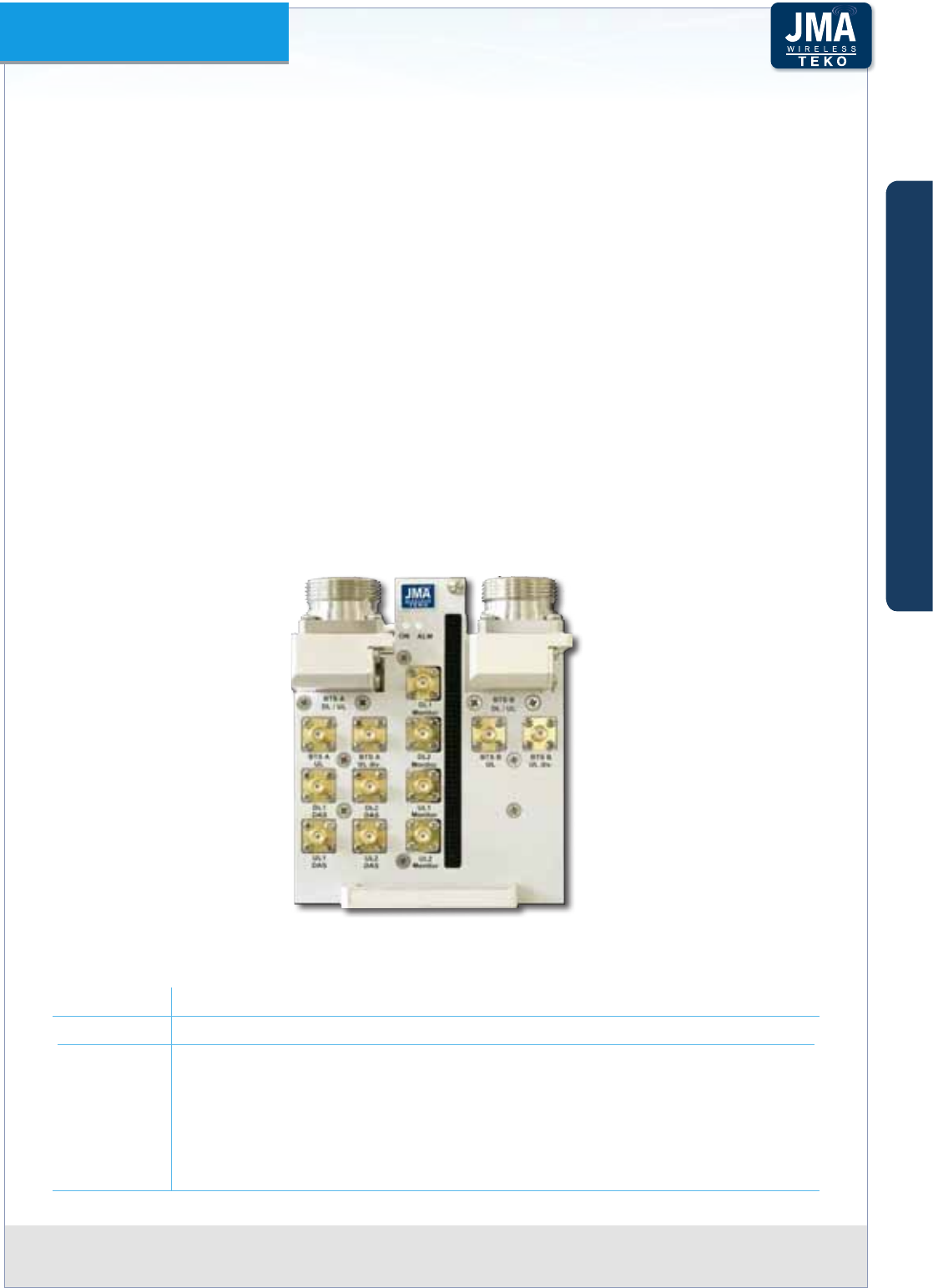
DAS Tray Point of Interface (TDTPOI) modules•
DAS Tray Point of Interface modules are used in Optical DAS to directly (no external directional
coupler nor load needed) interface any kind of operator signal source: BTS or NodeB/e-NodeB,
either duplex or simplex, with or without diversity, SISO or MIMO 2x2.
The TDTPOI-x-D (x=operating band) can be connected either to two SISO BTSs (with or without
diversity) or to one MIMO BTS. Dual TDTPOI models, geared to pick up the TDD reference
signals from BTS, are also available (please refer to Paragraph A.2.5).
TDTPOI are equipped with software-controlled attenuators for Downlink and Uplink RF levels
adjustment via the Coverage System Supervision Module and Management Tools.
RMS/Peak detectors and power limiter features enable monitoring of DL and UL signals. User-
dened thresholds allow for alarms to be generated and protection to the DAS system from
overpowering.
The Platform can be equipped with one DAS Tray or more to make multiple congurations
available: single operator (single-band / multi-band) and multi-operator (single-band / multi-
band).
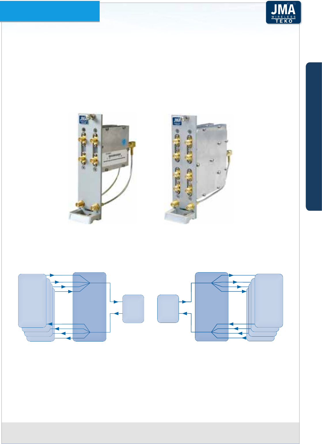
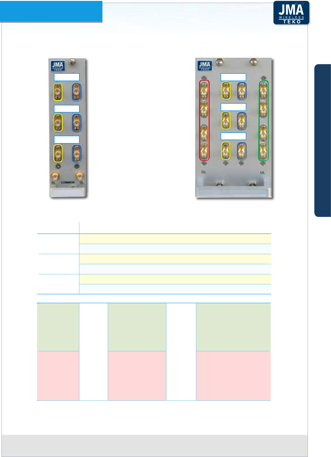
DAS Tray moduleFigure A1 –
TDTPOI-x-D DAS Tray module leds description•
Led Description
ON Module operating status green LED ON when power supply is present
ALM Module alarm status LED:
OFF: regular operation
Blinking Orange: presence of active alarms with warning severity level
Orange: presence of active alarms with minor severity level
Blinking Red: presence of active alarms with major severity level
Red: presence of active alarms with critical severity level
A
B
C
Components & Solutions

Teko DAS Platform Technical Handbook Doc ID Number 91 080 0783 rev. 01 | page A15
TEKO DAS Platform
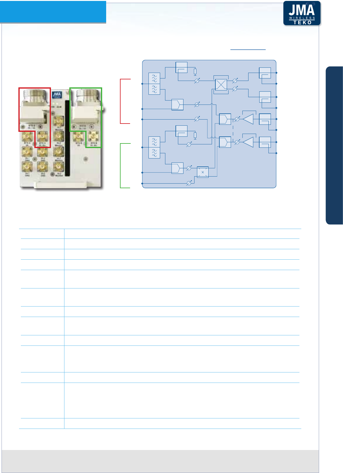
TDTPOI-x-D DAS Tray module Access Points and Block diagram - • BTS simplex
Access Points when the DAS TRAY is USED AS INTERFACE TOWARDS SIMPLEX BTS/
NodeB/e-NodeB (two SISO with or without diversity or one MIMO)
Label Description
BTS A DL/UL Simplex Downlink RF port (7/16-f ) - from BTS/NodeB/e-NodeB A
BTS A UL Simplex Uplink Output RF port (SMA-F) - to BTS/NodeB/e-NodeB A
BTS A UL div. SMA(f) Uplink Diversity RF port - to BTS/NodeB/e-NodeB A (from UL2 DAS)
BTS B DL/UL Simplex Downlink RF port from BTS/NodeB/e-NodeB B
BTS B UL Simplex Uplink Output RF port (SMA-F) - to BTS/NodeB/e-NodeB B
BTS B UL div. SMA(f) Uplink Diversity RF port - to BTS/NodeB/e-NodeB B (from UL2 DAS,
UMTS diversity; from UL1 DAS, GSM diversity)
DL1 DAS SMA(f) Downlink path RF output connector 1 (to DAS from BTS A separate
paths, from BTS A+BTS B combined paths)
DL1 Monitor SMA(f) DL1 DAS Monitor port
DL2 DAS SMA(f) Downlink path RF output connector 2 (to DAS from BTS B separate
paths, from BTS A+BTS B combined paths)
DL2 Monitor SMA(f) DL2 DAS Monitor port
UL1 DAS SMA(f) Uplink path RF input connector 1 from DAS to:
BTS A UL (MIMO 2x2); BTS A UL + BTS B UL (Dual SISO and UMTS diversity); BTS
A UL + BTS B UL diversity (GSM diversity)
UL1 Monitor SMA(f) UL1 DAS Monitor port
UL2 DAS SMA(f) Uplink path RF input connector 1 to:
BTS B UL (MIMO 2x2); BTS A UL + BTS B UL (Dual SISO); BTS A UL diversity + BTS
B UL diversity (UMTS diversity); BTS A UL diversity + BTS B UL (GSM diversity)
UL2 Monitor SMA(f) UL2 DAS Monitor port
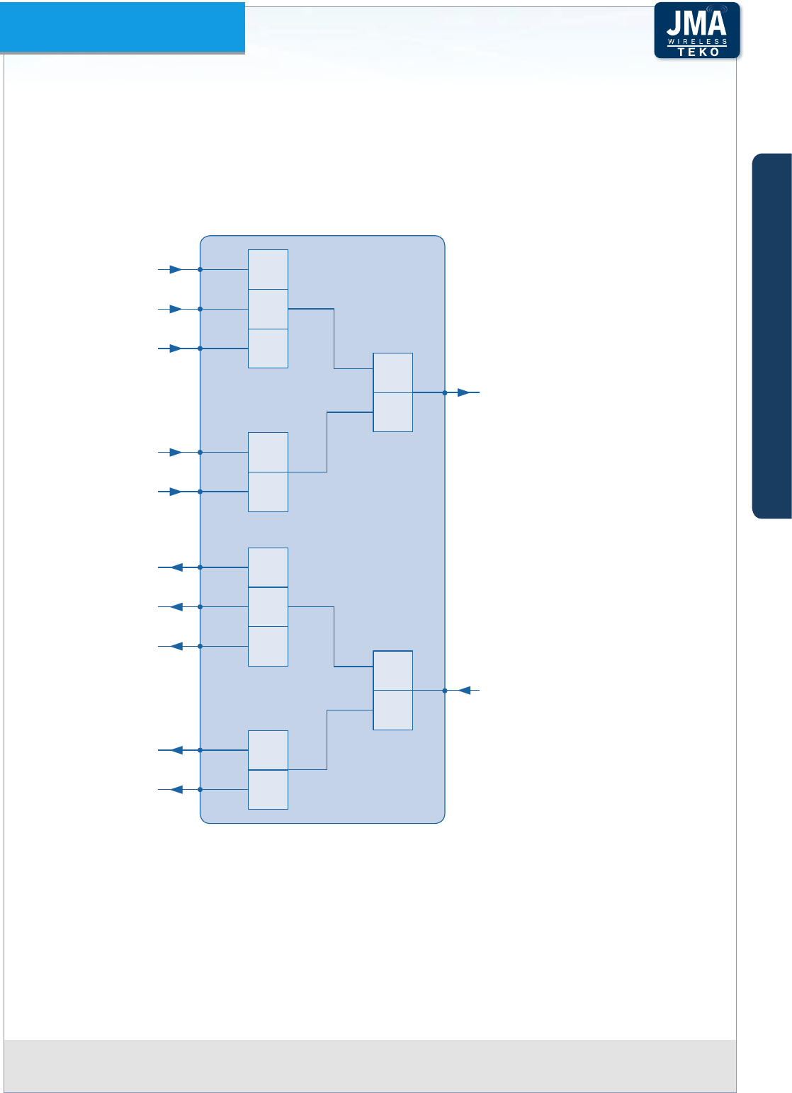
DAS Tray front view and block diagram - BTS simplexFigure A2 –
BTS A
DL SIMPLEX or
DL/UL DUPLEX
BTS B
DL SIMPLEX or
DL/UL DUPLEX
BTS A
UL SIMPLEX
BTS B
UL SIMPLEX
BTS A
UL DIVERSITY
BTS B
UL DIVERSITY
From/to
BTS A
From/to
BTS B
50
LOAD
50
LOAD
MONITOR
TO DASDL1
MONITOR
TO DASDL2
MONITOR
MONITOR
FROM DASUL1
FROM DASUL2
A
B
C
Components & Solutions
Teko DAS Platform Technical Handbook Doc ID Number 91 080 0783 rev. 01 | page A16
TEKO DAS Platform
TDTPOI-x-D DAS Tray module Access Points and Block diagram - • BTS duplex
Access Points when the DAS TRAY is USED AS INTERFACE TOWARDS DUPLEX BTS
(two SISO BTSs with or without diversity or one MIMO BTS)
Label Description
BTS A DL/UL Duplex port (7/16-f) from (DL) /to (UL) BTS/NodeB/e-NodeB A
BTS A UL div. SMA(f) Uplink Diversity RF port - to BTS/NodeB/e-NodeB A (from UL2 DAS)
BTS B DL/UL Duplex port (7/16-f) from (DL) /to (UL) BTS/NodeB/e-NodeB B
BTS B UL div. SMA(f) Uplink Diversity RF port - to BTS/NodeB/e-NodeB B (from UL2 DAS,
UMTS diversity; from UL1 DAS, GSM diversity)
DL1 DAS SMA(f) Downlink path RF output connector 1 (from BTS A separate paths,
from BTS A+BTS B combined paths)
DL1 Monitor SMA(f) DL1 DAS Monitor port
DL2 DAS SMA(f) Downlink path RF output connector 2 (from BTS B separate paths,
from BTS A+BTS B combined paths)
DL2 Monitor SMA(f) DL2 DAS Monitor port
UL1 DAS SMA(f) Uplink path RF input connector 1 to:
BTS A DL/UL (MIMO 2x2); BTS A DL/UL + BTS B DL/UL (Dual SISO and UMTS
diversity); BTS A DL/UL + BTS B UL diversity (GSM diversity)
UL1 Monitor SMA(f) UL1 DAS Monitor port
UL2 DAS SMA(f) Uplink path RF input connector 1 to:
BTS B DL/UL (MIMO 2x2); BTS A DL/UL + BTS B DL/UL (Dual SISO); BTS A UL
diversity + BTS B UL diversity (UMTS diversity); BTS A UL diversity + BTS B DL/
UL (GSM diversity)
UL2 Monitor SMA(f) UL2 DAS Monitor port
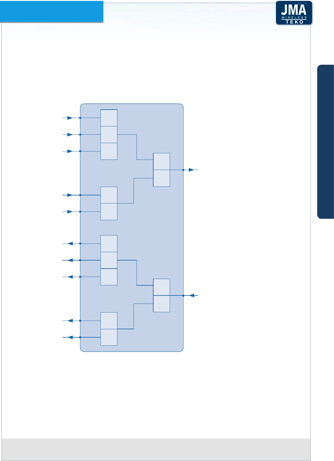
DAS Tray front view and block diagram - BTS duplexFigure A3 –
BTS A
DL SIMPLEX or
DL/UL DUPLEX
BTS B
DL SIMPLEX or
DL/UL DUPLEX
BTS A
UL SIMPLEX
BTS B
UL SIMPLEX
BTS A
UL DIVERSITY
BTS B
UL DIVERSITY
From/to
BTS A
From/to
BTS B
50
LOAD
50
LOAD
MONITOR
TO DASDL1
MONITOR
TO DASDL2
MONITOR
MONITOR
FROM DASUL1
FROM DASUL2
A
B
C
Components & Solutions
Teko DAS Platform Technical Handbook Doc ID Number 91 080 0783 rev. 01 | page A17
TEKO DAS Platform
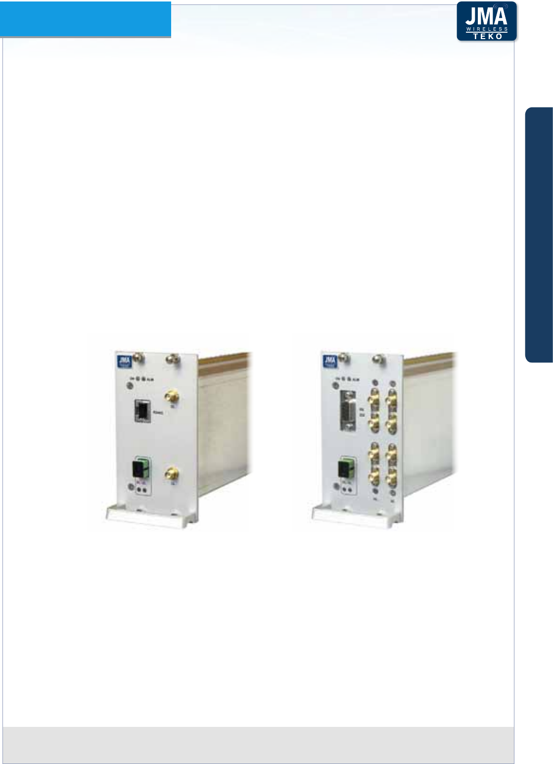
Point Of Interface Modules•
PointofInterfacemodulesareusedinOpticalDAStointerfacetheoperatorsignalsource-BS
orO-AirRepeater.EachPointofInterfaceisconnectedtoasinglemobileoperator/mobile
bandsignalsourceviacoaxialcable.
Optical Systems can be equipped with one Point of Interface or more Point of Interface
modulestomakemultiplecongurationsavailable:singleoperator(singleband/multi-band)
andmulti-operator(single-band/multi-band).
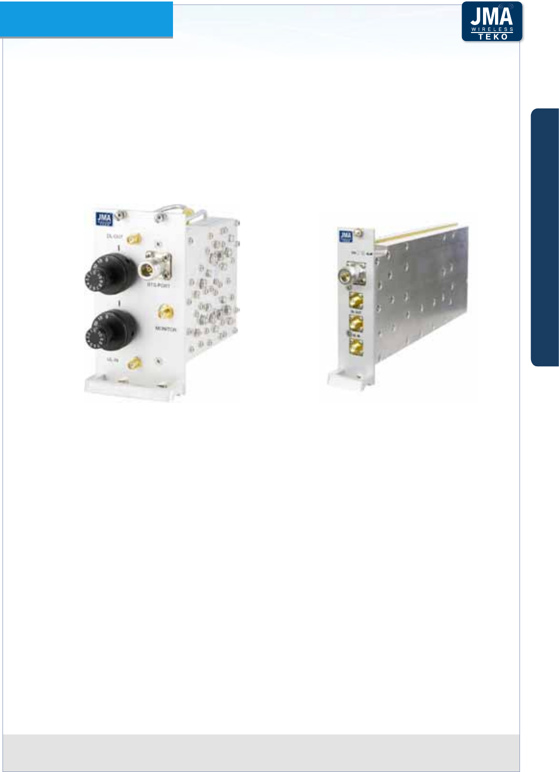
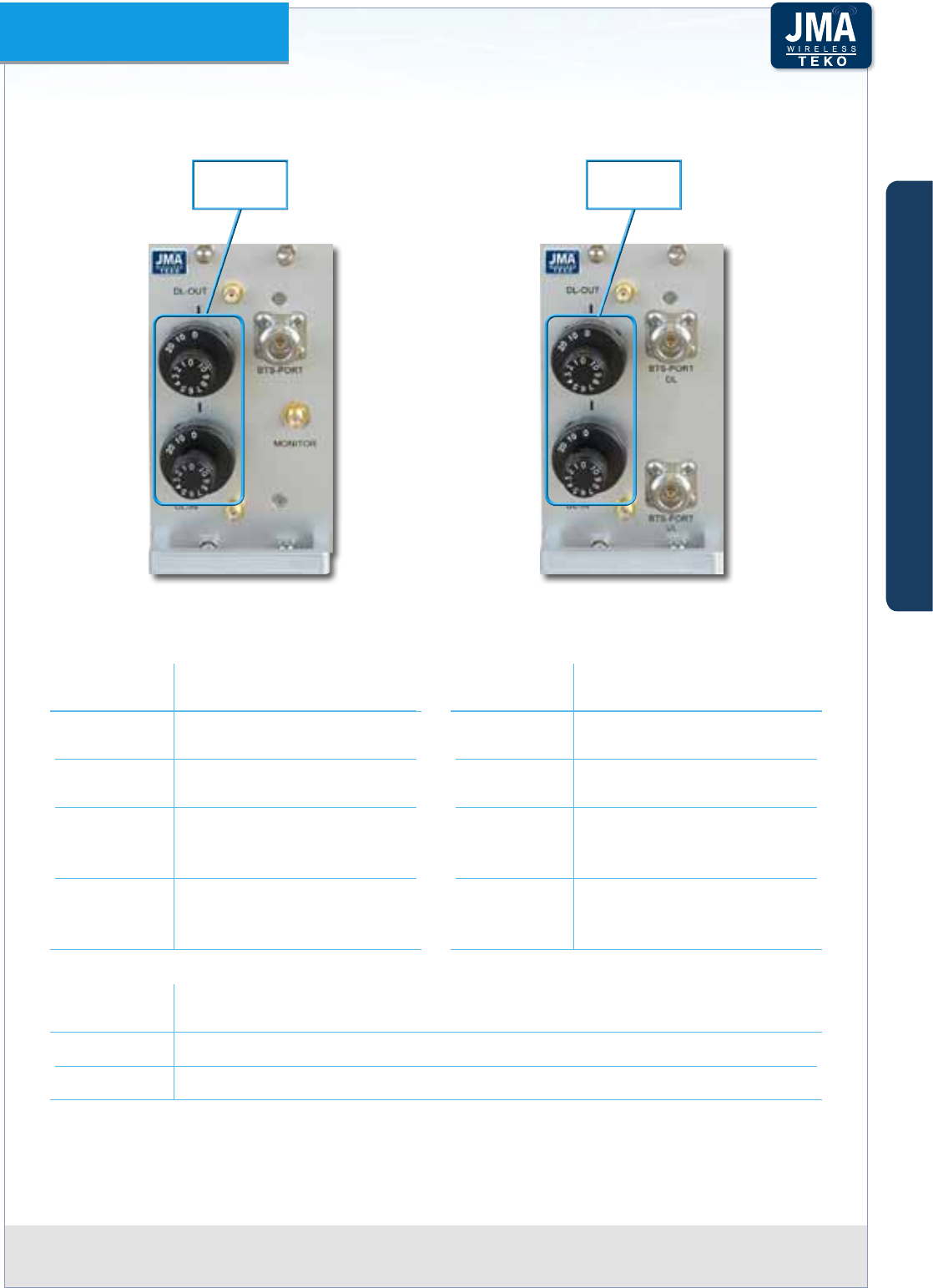
PointOfInterfaceFigureA4– (POI)Modules:PassivePOI(left)andActiveTAPOI(right)
TekoPointofInterfacemodulescanbeequippedeitherwithmanuallyadjustableattenuators
(POI-xmodels)orwithremote-controlledattenuators(TAPOI-xmodels).
POI modules
EachPOImoduleincludestheduplexer,toseparate/combineDownlinkandUplinkpathsand
tworotary adjustable attenuatorsto make both DownlinkandUplinkRFlevelsseparately
adjustable, within a range of either 30dB, with 1dB step, or 10dB, with 1dB step (POI-A10
models).
A
B
C
Components & Solutions
Teko DAS Platform Technical Handbook Doc ID Number 91 080 0783 rev. 01 | page A18
TEKO DAS Platform
A monitor port is available either for measurements or for external wireless modem
coupling.
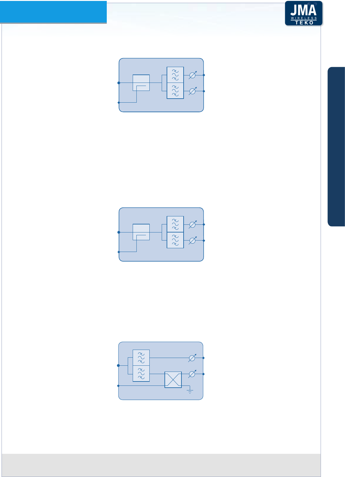
Point Of Interface module block diagramFigure A5 –
BTS PORT
MONITOR
UL IN
DL OUT
UL
DL
TAPOI modules
Several models of TAPOI modules are available:
Duplex TAPOI (Commercial code: TAPOI-• band): include the duplexer, to separate/combine
Downlink and Uplink paths and two automated variable attenuators to adjust Downlink
and Uplink RF levels via the Coverage System Supervision Module (TSPV) and Management
Tools (OMT webpages, OMC software). Duplex TAPOI modules make a monitor port available
for measurements/external wireless modem coupling.
Duplex TAPOI - Block diagramFigure A6 –
BTS PORT
MONITOR
UL IN
DL OUT
UL
DL
Simplex TAPOI (Commercial code: TAPOI-band code-TRX): TAPOI modules without built-in •
duplexer provide separate Downlink and Uplink ports.
Flexible TAPOI (Commercial code: TAPOI-• band code-F)
Flexible TAPOI can operate either as duplex or simplex TAPOI modules: they include both a
BTS duplex port (N type) and a simplex Uplink BTS port (BTS UL, SMA type).
Flexible TAPOI - Block diagramFigure A7 –
UL IN
DL OUT
BTS DL+UL or
BTS DL PORT
BTS UL
(OUT)
UL
DL
A
B
C
Components & Solutions
Teko DAS Platform Technical Handbook Doc ID Number 91 080 0783 rev. 01 | page A19
TEKO DAS Platform
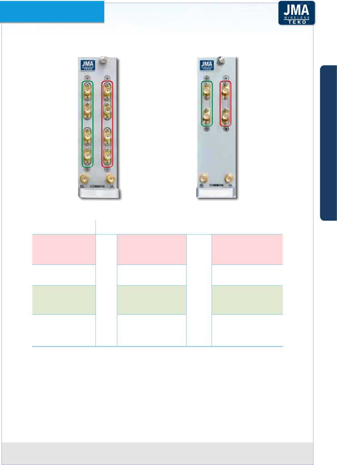
POI Modules Access Points•
Passive POI - with built-in duplexer (left) without built-in duplexer (right)Figure A8 –
Adjustable
attenuators
Adjustable
attenuators
Label
(Connectors)
Description
DL-OUT Downlink path RF output
(SMA connector)
UL-IN Uplink path RF input (SMA
connector)
BTS PORT
RF connector (N type) towards
the signal source (BTS, Node
B/e-Node B or repeater)
MONITOR
Monitor port for
measurements or for external
wireless modem coupling
Label
(Connectors)
Description
DL-OUT Downlink path RF output
SMA connector
UL-IN Uplink path RF input SMA
connector
BTS PORT DL
Input RF connector (N type)
from the signal source - BTS,
Node B/e-NodeB or repeater
BTS PORT UL
Output RF connector to the
signal source - BTS, NodeB/e-
NodeB or repeater (N type)
Adjustable
attenuators
Description
DL OUT Downlink path RF level adjustable attenuator (0÷30dB or 0÷10dB - 1 dB step)
UL IN Uplink path RF level adjustable attenuator (0÷30dB or 0÷10dB - 1 dB step)
A
B
C
Components & Solutions
Teko DAS Platform Technical Handbook Doc ID Number 91 080 0783 rev. 01 | page A20
TEKO DAS Platform
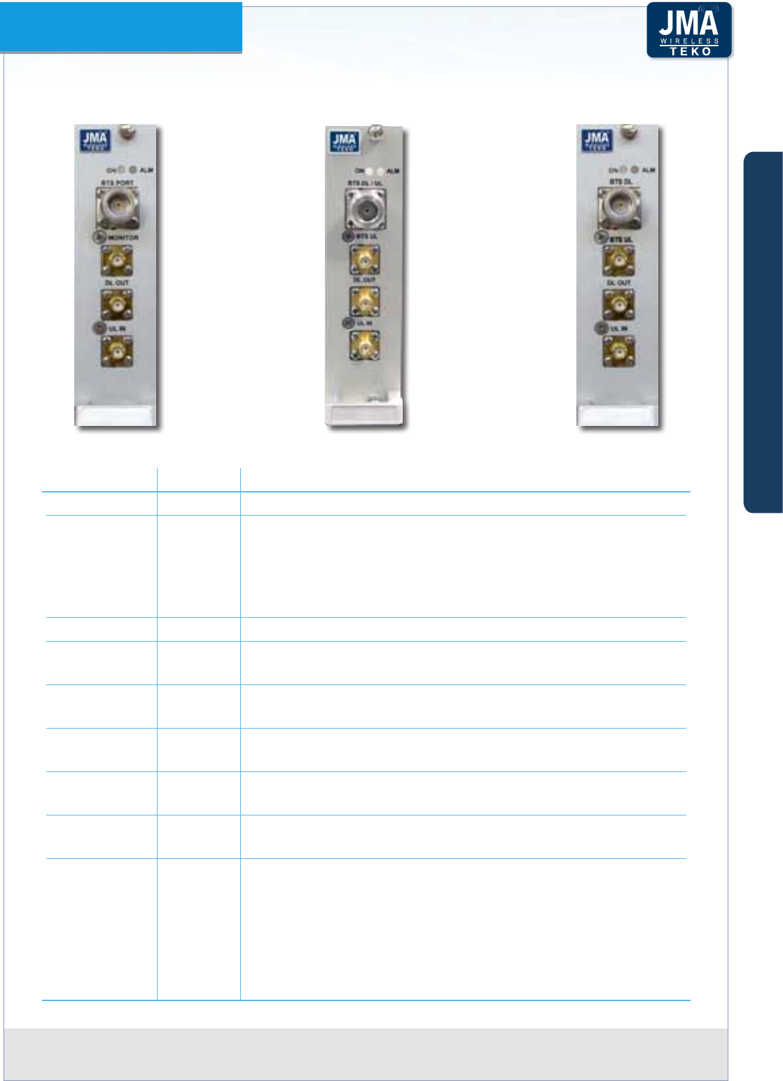
TAPOI Modules Access Points•
Active Figure A9 – TAPOI: Duplex (left), Flexi (center), Simplex (right)
TAPOI model Label Description
Duplex BTS PORT Duplex port from/to BTS/NodeB/e-NodeB/repeater (N type)
Flexi BTS DL/UL Duplex port (N or 4.3-10, female type) from /to BTS/NodeB/e-
NodeB/repeater
or
Downlink RF port (N or 4.3-10, female type) from BTS/NodeB/
e-NodeB/repeater
Simplex BTS DL Input RF port (N type) from BTS/NodeB/e-NodeB/repeater
Duplex MONITOR Monitor port for either measurements or external wireless
modem coupling
Flexi
Simplex
BTS UL Output RF port (SMA type) - to BTS/NodeB/e-NodeB/
repeater
Duplex/Flexi
Simplex
DL OUT Downlink path RF output connector (SMA type)
Duplex/Flexi
Simplex
UL IN Uplink path RF input connector (SMA type)
Duplex/Flexi
Simplex
ON TAPOI Module operating status green LED ON when power
supply is present
Duplex/Flexi
Simplex
ALM TAPOI Module alarm status LED:
OFF: regular operation
Blinking Orange: presence of active alarms with warning
severity level
Orange: presence of active alarms with minor severity level
Blinking Red: presence of active alarms with major severity level
Red: presence of active alarms with critical severity level
A
B
C
Components & Solutions
Teko DAS Platform Technical Handbook Doc ID Number 91 080 0783 rev. 01 | page A21
TEKO DAS Platform
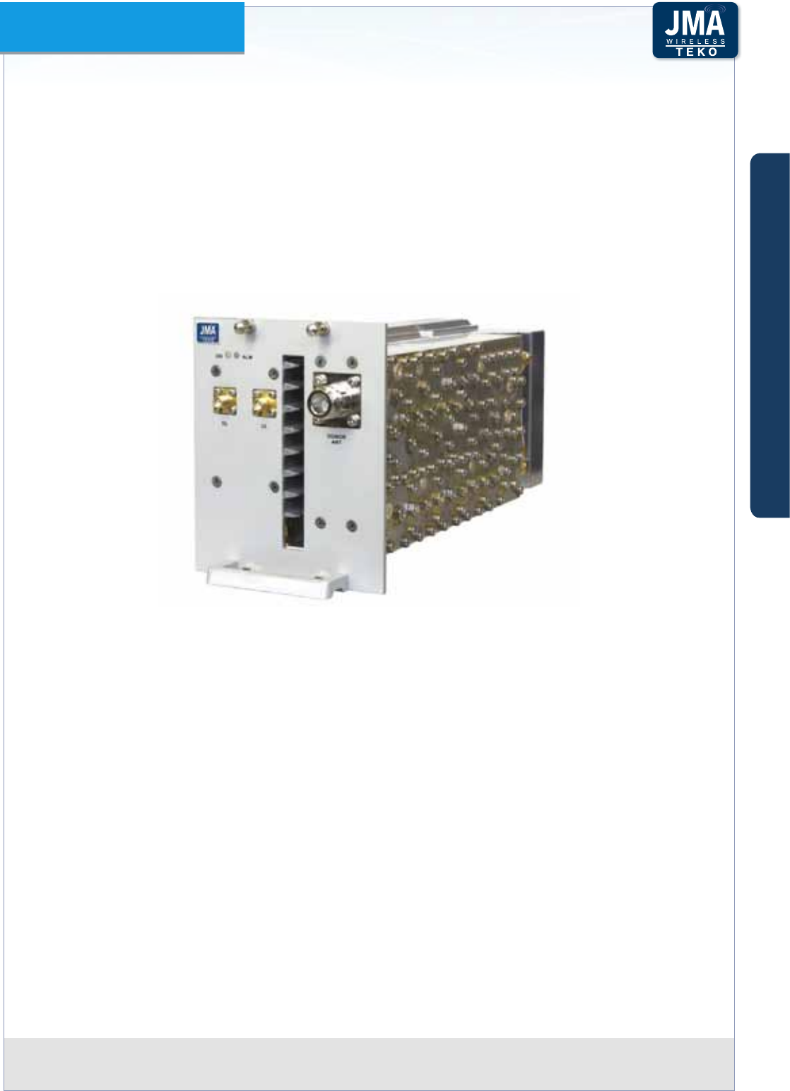
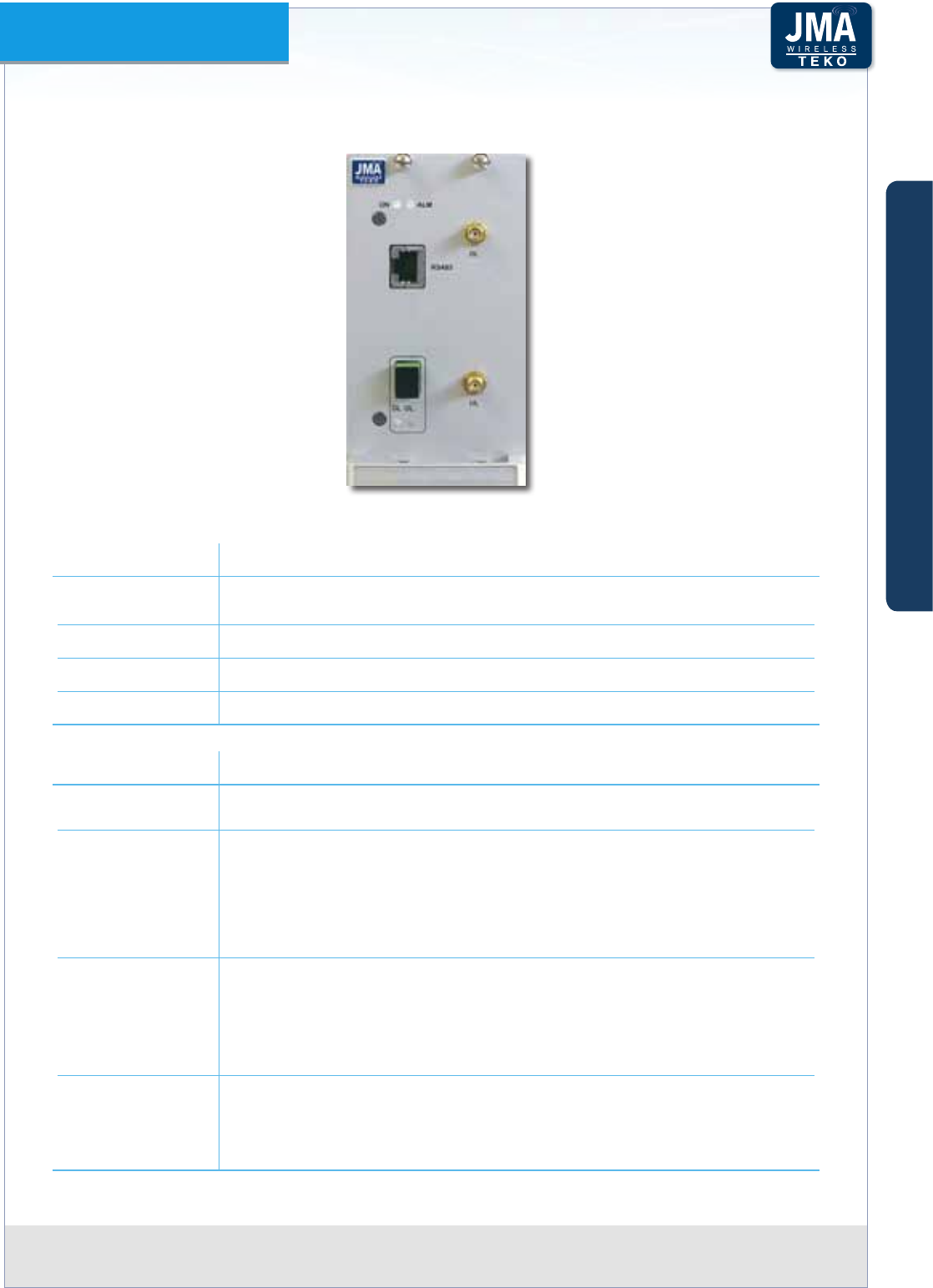
Teko Digital Donor Front End (TDFE)•
The Digital Donor Front End Module is the single-band/single-operator System RF interface
towards a Donor Antenna, providing Downlink digital ltering and Uplink Power Amplier.
No physical connections are required between the DFE and the cellular network: the Donor
Antenna provides the connection to a BTS or NodeB/e-NodeB over an air link.
Coverage Systems can be equipped with one or more Donor Front End modules to make
multiple congurations available: single operator (single band / multi-band) and multi-
operator (single-band / multi-band).
Digital Donor Front End (TDFE)Figure A10 –
A single-band single-operator modular O-air Repeater can be set up combining a Digital
Donor Front End Module and a Service Front End (Teko single-band/multi-operator interface
towards a Service Antenna). Up to 4 Donor Front End Modules can be connected to a single
Service Front End to provide a single-band 4-operator modular O-air Repeater.
Digital Donor Front End Modules can also be used to drive Optical Systems: the Digital Donor
Front End Module allows Optical Systems to be driven without the need of a dedicated BTS
or NodeB/e-NodeB. A donor antenna picks-up the signal and the Optical System acts as a
repeater with distributed Service antennas connected to the Remote Units. Service Front
End subracks can be connected to DFE modules to provide coverage to the area next to the
Master Unit site.
A
B
C
Components & Solutions
Teko DAS Platform Technical Handbook Doc ID Number 91 080 0783 rev. 01 | page A22
TEKO DAS Platform
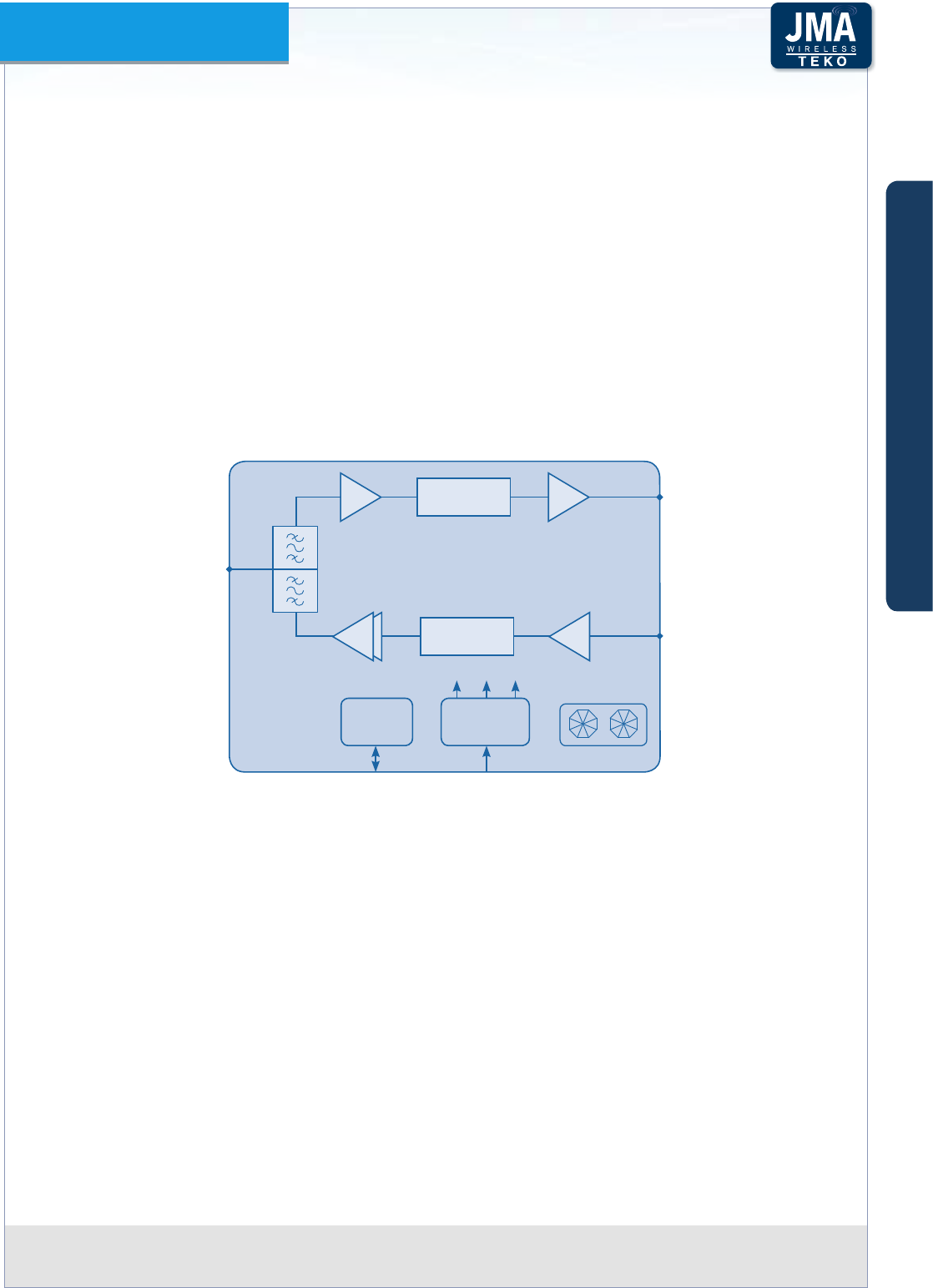
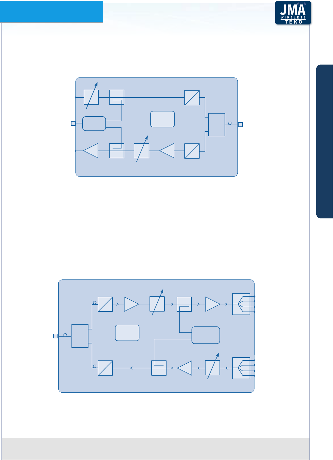
Each DFE module hosts the duplexer, to be connected to the Donor Antenna to separate/
combine downlink and uplink paths.
In downlink the signal from the Donor Antenna is preamplied by a Low Noise Amplier and
converted into an IF signal by a down converter. The selection of the band of frequencies or
channels to be extended is handled by a digital lter.
The digital lter can manage 1 variable band or 2 variable sub-bands (standard version). A
fully equipped version is available to manage up to 9 variable sub-bands.
An up converter converts the IF signal into the RF output signal.
In uplink the signal from the Service Front End Subrack or from the Optical System is converted
into an IF signal by a down converter, ltered and re-converted into an RF signal, amplied by
a power amplier and re-transmitted to the signal source.
DL RF
Out
UL RF
In
Donor
Antenna
Port
Duplexer
P DC/DC
+12V +1.8V+3.3V
28÷30VDC
RS485
FANS
Digital Filter
Digital Filter
PA
LNA
Digital Donor Front End Module block diagramFigure A11 –
A
B
C
Components & Solutions
Teko DAS Platform Technical Handbook Doc ID Number 91 080 0783 rev. 01 | page A23
TEKO DAS Platform
Digital Donor Front End Module Access Points
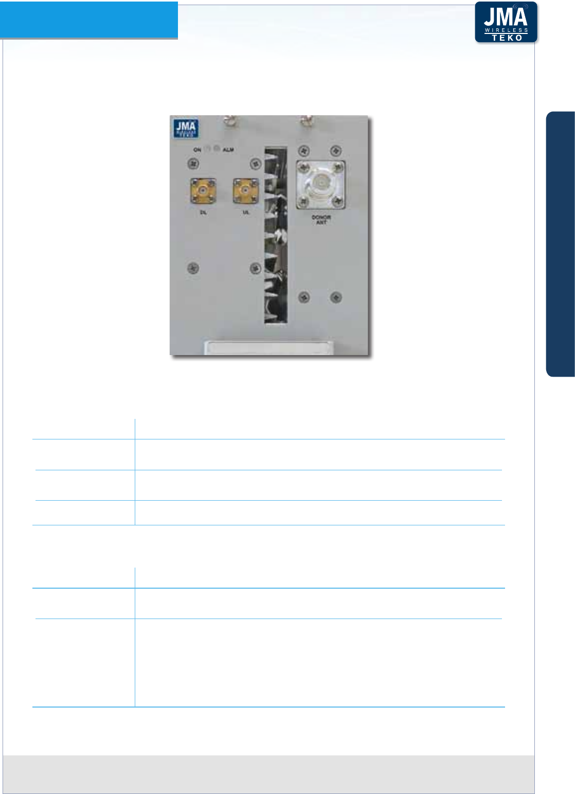
Digital Donor Front End (TDFE) front viewFigure A12 –
Label (Connectors) Description
DL Downlink path RF output (SMA connector) to Service Front End or Fiber
Optic Modules
UL Uplink path RF input (SMA connector) from Service Front End or Fiber
Optic Modules
DONOR ANT Donor Antenna Port (N type connector)
Label (LEDs) Description
ON Digital Donor Front End Module operating status green LED:
ON when power supply is present
ALM
Digital Donor Front End Module alarm status LED:
OFF: regular operation
Blinking Orange: presence of active alarms with warning severity level
Orange: presence of active alarms with minor severity level
Blinking Red: presence of active alarms with major severity level
Red: presence of active alarms with critical severity level
A
B
C
Components & Solutions
Teko DAS Platform Technical Handbook Doc ID Number 91 080 0783 rev. 01 | page A24
TEKO DAS Platform
Equipment extending coverage / distributing capacityA.2.2
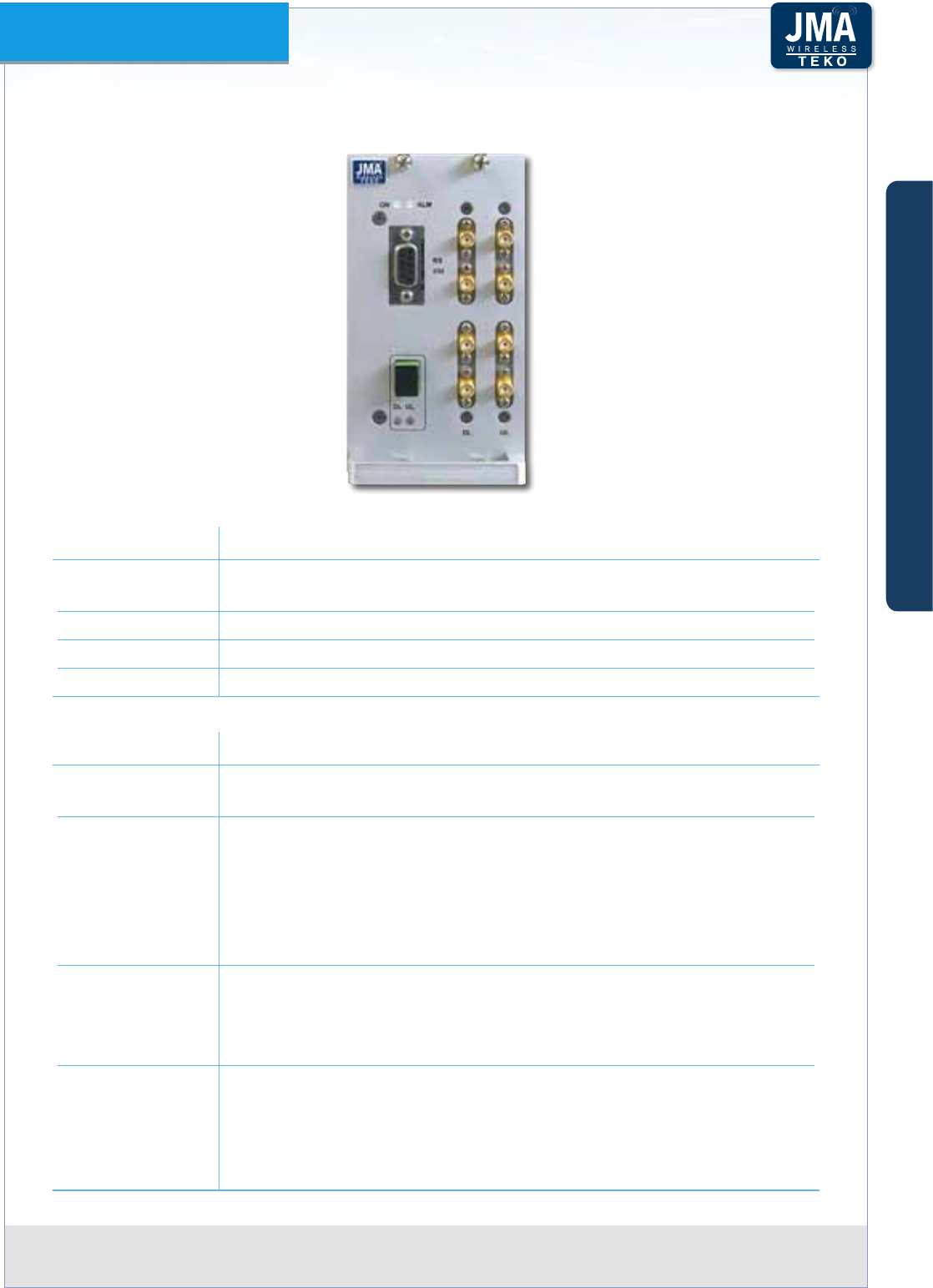
Teko Service Front End (TSFE)•
Teko Service Front End is a single-band/multi-operator equipment, driven by Digital Donor
Front End Modules and connected to the Service Antenna/Leaky Cable to provide wireless
signal to the area to be covered. The equipment is available in dierent power classes.
A single-band single-operator modular O-air Repeater can be set-up combining a Digital
Donor Front End Module and a Service Front End. Up to 4 Donor Front End Modules can
be connected to a single Service Front End subrack to provide a single-band 4-operator
Repeater.
The Service Front End subrack can also be used in Optical Systems to provide coverage to the
area adjoining the Master Unit site.
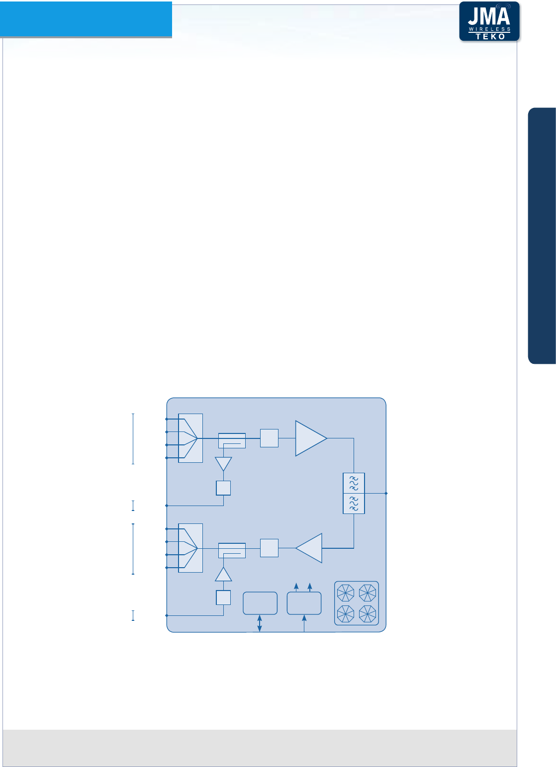
The TSFE 19”/2U subrack hosts the duplexer, to be connected to the Service Antenna to
separate/combine Downlink and Uplink paths.
In Downlink the signals from the Donor Front-End Modules are combined and amplied by a
Power Amplier.
In Uplink, the RF signal from the Service antenna is amplied by a Low Noise Amplier (LNA)
and split to feed up to 4 Donor Front-End Modules.
Auxiliary ports are available to drive an Optical System.
PA
DL in1
Service
Antenna
Port
Duplexer
P DC/DC
+3.3V +5V
28÷30VDCRS485
Digital
Attenuator
DL in2
DL in3
DL in4
DL out
LNA
UL out1 Digital
Attenuator
UL out2
UL out3
UL out4
UL in
Digital
Attenuator
Digital
Attenuator
4:1
4:1
FANS
From DFEs
To DFEs
To Optics
From Optics
Service Front End block diagramFigure A13 –
A
B
C
Components & Solutions
Teko DAS Platform Technical Handbook Doc ID Number 91 080 0783 rev. 01 | page A25
TEKO DAS Platform
Service Front End Access Points
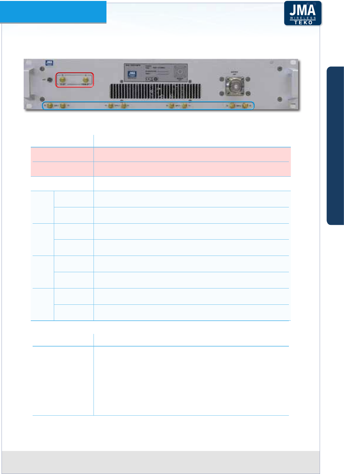
Service Front End front viewFigure A14 –
Label (Connectors) Description
DL TO OPT Downlink path RF output (SMA connector) - to Optics
UL FROM OPT Uplink path RF input (SMA connector) - from Optics
SERVICE ANT Service Antenna Port (N type )
DFE1
DL Downlink path RF input (SMA connector) - from Digital Donor
Front End 1
UL Uplink path RF output (SMA connector) - to Digital Donor Front
End 1
DFE2
DL Downlink path RF input (SMA connector) - from Digital Donor
Front End 2
UL Uplink path RF output (SMA connector) - to Digital Donor Front
End 2
DFE3
DL Downlink path RF input (SMA connector) - from Digital Donor
Front End 3
UL Uplink path RF output (SMA connector) - to Digital Donor Front
End 3
DFE4
DL Downlink path RF input (SMA connector) - from Digital Donor
Front End 4
UL Uplink path RF output (SMA connector) - to Digital Donor Front
End 4
Label (LEDs) Description
LED
Service Front End subrack general operating status LED
Green: no alarm
Blinking Orange: presence of active alarms with warning
severity level
Orange: presence of active alarms with minor severity level
Blinking Red: presence of active alarms with major severity
level
Red: presence of active alarms with critical severity level
A
B
C
Components & Solutions
Teko DAS Platform Technical Handbook Doc ID Number 91 080 0783 rev. 01 | page A26
TEKO DAS Platform
Teko Remote Units•
Remote Units distribute wireless signals throughout the area to be covered. They are connected
to the Fiber Optic Transmitter/Receiver Modules equipped in the Master Unit.
Remote Units are equipped with the Fiber Optic Receiver and Transmitter module (for Optical
to RF and RF to Optical conversion), power ampliers and ltering.
They can be Single band or Multi-band with dierent RF power classes.
Remote Units with dierent power classes can be driven simultaneously by the same Master
Unit to distribute capacity or extend coverage into dierent locations at the same time.
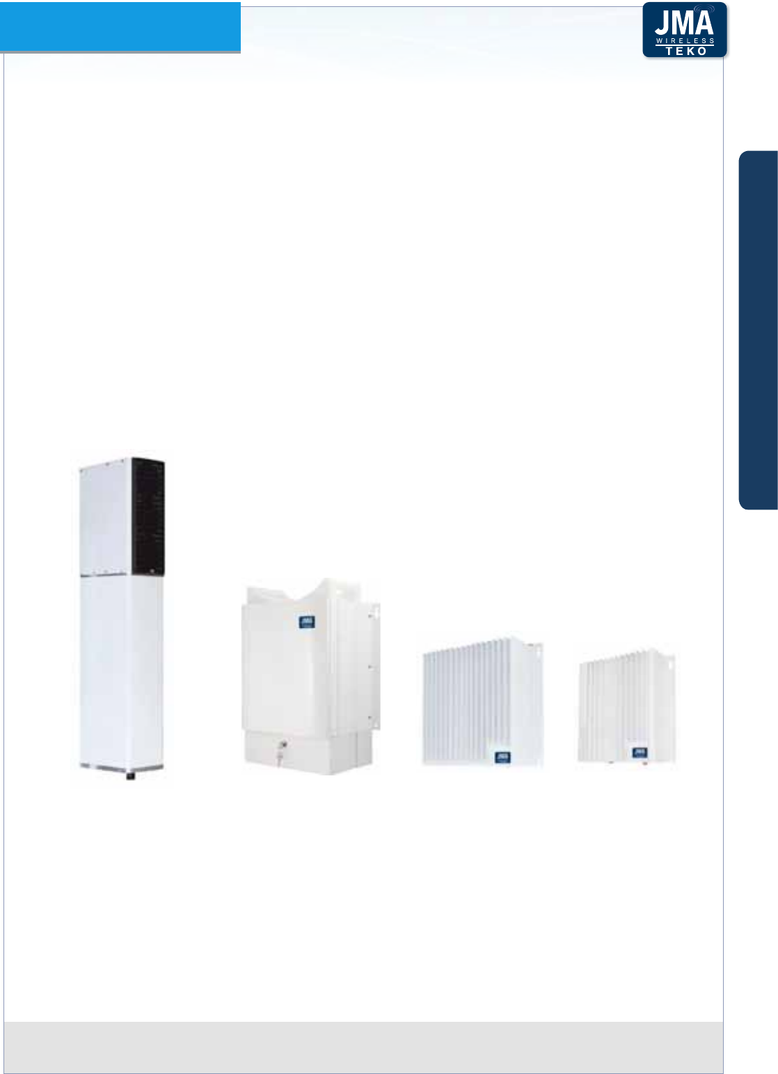
Pole-mount and boxed Remote Units (except Low Power) are equipped in a weatherproof
IP66 rating case.
Low Power Remote Units are equipped in an IP32 case; a protection kit, providing IP66 rating,
is available as option for harsh environment installation.
The pole-mounting Remote Unit mechanical design allows the Unit to be mounted inside
utility poles with 12” internal radius.
Pole-mount Remote Unit Boxed Remote Unit Low Power Remote Units
Please refer to page A70 for a detailed description of Remote Units.
A
B
C
Components & Solutions
Teko DAS Platform Technical Handbook Doc ID Number 91 080 0783 rev. 01 | page A27
TEKO DAS Platform
Modules providing the optical interface towards Remote UnitsA.2.3
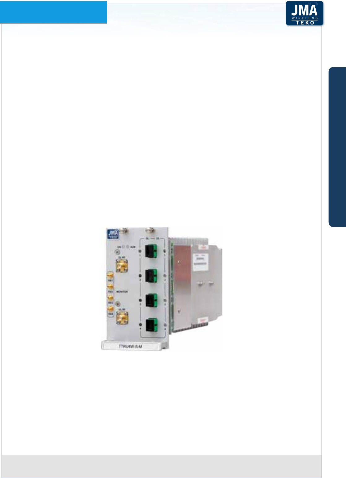
Fiber Optic Transmitter/Receiver Modules•
Fiber Optic Transmitter/Receiver Modules are the optical interface between Master Unit and
Remote Units: they provide RF-to-Optical/Optical-to-RF conversion. They are connected to
Remote Units via single mode optical bers, with Uplink and Downlink signals transmitted
over a single strand of ber (Wavelength Division Multiplexing -WDM technology).
Dierent congurations are available: a single Fiber Optic Transmitter/Receiver Module can
be equipped with 1 Optical Transmitter and 1 Optical Receiver (10dB optical link budget, up
to 20km distance - 12.4 miles), or 1 Optical Transmitter split by 2 and 2 combined Optical
Receivers (10dB optical link budget, up to 20km distance- 12.4 miles), or 1 Optical Transmitter
split by 4 and 4 combined Optical Receivers (6dB optical link budget, up to 12km distance -
7.5 miles).
The Fiber Optic Transmitter/Receiver Module in 1:4 conguration can manage up to 4 Remote
Units.
The Fiber Optic Transmitter/Receiver Module in 1:1 conguration is able to drive up to 5
cascaded Remote Units with dierent wavelengths in Uplink.
Fiber Optic Transmitter/Receiver Module (1:4 conguration) with monitor for E9-1-1 service and Figure A15 –
Multiband Spectrum Analyzer connection
The Fiber Optic Transmitter provides the RF to optical conversion (Downlink side): the module
RF section covers the 380 to 2700MHz band (TTRU models).
Fiber Optic Receivers convert uplink optical signals from Remote Units into RF. They operate
in the third window (Optical wavelength 1490 ÷ 1570 nm).
A
B
C
Components & Solutions
Teko DAS Platform Technical Handbook Doc ID Number 91 080 0783 rev. 01 | page A28
TEKO DAS Platform
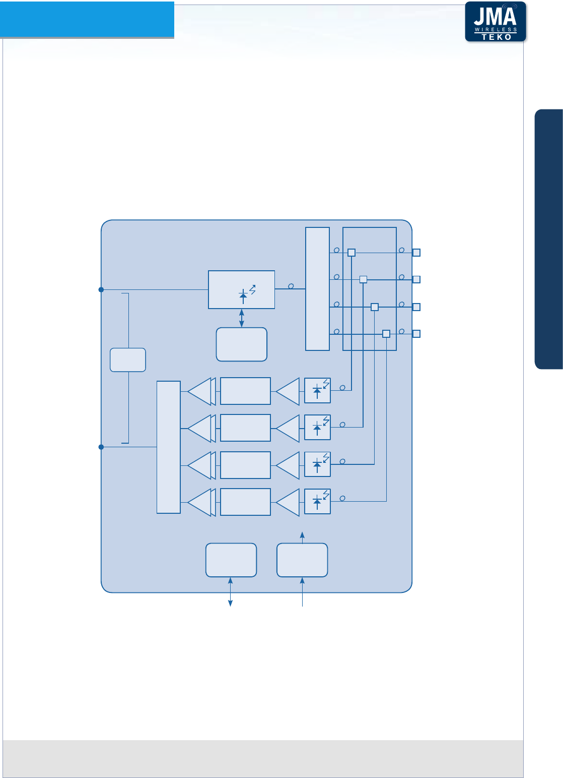
Each Fiber Optic module is controlled by a microprocessor which provides the following data
to the Supervision Module:
optical power received by each optical receiver, -
Downlink attenuator and Uplink attenuator attenuation setting (0 ÷ 15dB), -
received optical power alarms. -
An auto-levelling functionality (AGC) compensates up to 10dB optical link loss in order
to guarantee constant gain over dierent optical budgets. This feature simplies system
installation, makes commissioning quick and easy and avoids eld adjustments.
CONTROL
1:4
OPT
MODEM
4:1
P DC/DC
28÷30VDCRS485
PA DIGITAL
ATTENUATOR LNA
PA DIGITAL
ATTENUATOR LNA
PA DIGITAL
ATTENUATOR LNA
PA DIGITAL
ATTENUATOR LNA
DL RF WDM
DL/UL 1
DL/UL 3
DL/UL 2
DL/UL 4
UL RF
LASER
Block diagram: Fiber Optic Transmitter/Receiver Module equipped with 1 Optical Transmitter split Figure A16 –
by 4 and 4 combined Optical Receivers (WDM technology)
A
B
C
Components & Solutions
Teko DAS Platform Technical Handbook Doc ID Number 91 080 0783 rev. 01 | page A29
TEKO DAS Platform
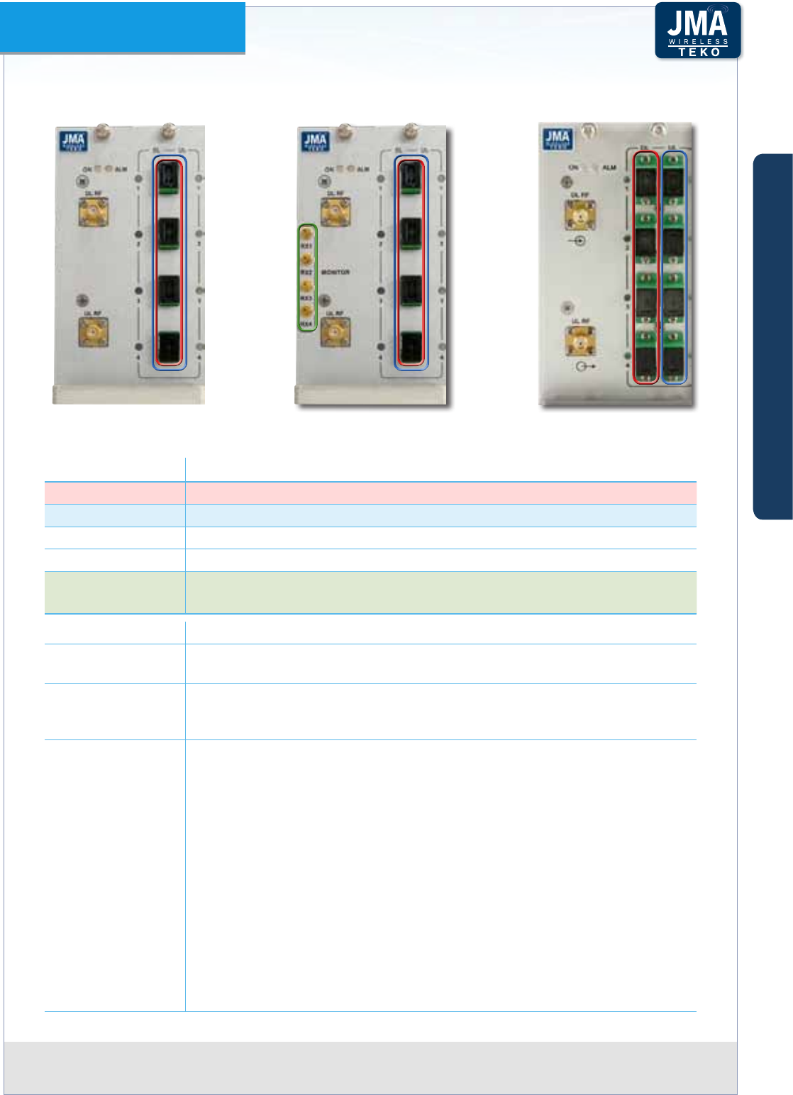
Fiber Optic Transmitter/Receiver Module Access Points
Label (Connectors) Description
DL (1 to 4) Fiber Optic Transmitters optical output connectors (SC-APC)-laser aperture
UL (1 to 4) Fiber Optic Receivers optical input connectors (SC-APC)
DL RF Fiber Optic Transmitter RF input SMA connector
UL RF Fiber Optic Receiver RF output SMA connector
Monitor RXn Remote Units Monitor ports (1 to 4) - SSMB (m) connectors for E 9-1-1 service
and Multiband Spectrum Analyzer connection
Label (LEDs) Description
ON Fiber Optic Module operating status green LED
ON when power supply is present
ALM
Fiber Optic Module alarm status LED:
OFF: regular operation; BLINKING ORANGE/ORANGE: warning/minor;
BLINKING RED/RED: major/critical
DL UL
These LEDs describe the general operating status of Remote Units (1 to
4) connected to Fiber Optic Transmitters (DL) and Repeaters (UL) .
Each pair of DL/UL leds takes the same color as the general operating status
led of the Remote Unit connected to the optical connector, except when
a Laser Fault occurs in the Fiber Optic transmitter. If this fault occurs, all •
DL leds turn RED and the ALM Led switches on (RED).
a Low Optical Power alarm arises in the Fiber Optic receiver. If this alarm •
arises, the UL led turns RED and the ALM Led switches on (RED).
Each pair of DL/UL LEDs can be:
Green: Remote Unit status OK
Blinking Orange: presence of RU active alarms with warning severity level
Orange: presence of RU active alarms with minor severity level
Blinking Red: presence of RU active alarms with major severity level
Red: presence of RU active alarms with critical severity level
Fiber Optic Module 1:4
conguration
Fiber Optic Module 1:4
conguration - WDM
Fiber Optic Module 1:4
conguration - WDM with
SSMB ports
A
B
C
Components & Solutions
Teko DAS Platform Technical Handbook Doc ID Number 91 080 0783 rev. 01 | page A30
TEKO DAS Platform
Master and Slave Point to Point Modules•
Master and Slave Point to Point Modules provide an optical point to point link allowing a
separation distance -up to 20km- between RF interface subracks and slave optical subracks.
The point to point link is suitable when the signal source (BTS, NodeB/e-NodeB, Repeater) is
located far from the area to be covered or when the same optical system provides coverage to
several separate buildings; in these applications the point to point link allows the transmission
of signals from/to a group of remote units over a single strand of optical ber, thus providing
a signicant reduction in the number of ber optics running long distances.
The point to point link requires the RF interface subracks to be equipped with Master Point
to Point modules and the remote (slave) optical subracks to be equipped with Slave Point
to Point modules. The RF Interface subracks can be equipped with up to 4 Master Point to
Point modules for the management of up to 4 optical subracks, installed in dierent remote
locations.
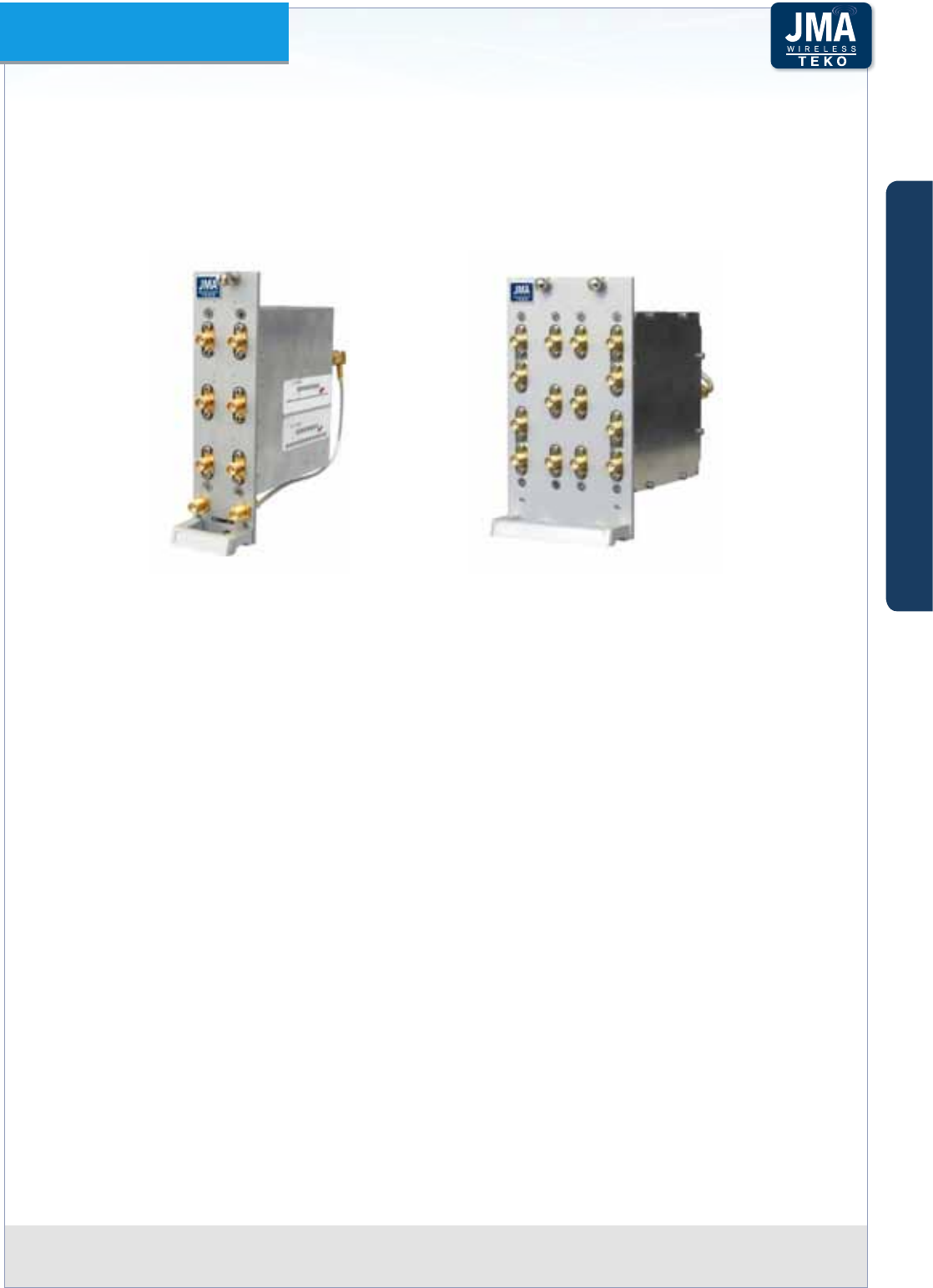
Point to Point Modules: Master (left) and Slave (right)Figure A17 –
Master and Slave Point to Point Modules are connected via a single optical ber (single-mode
SMR 9/125).
Each Slave optical subrack can be equipped with up to 3 Slave Point to Point Modules for the
coverage of up to 3 sectors.
A
B
C
Components & Solutions
Teko DAS Platform Technical Handbook Doc ID Number 91 080 0783 rev. 01 | page A31
TEKO DAS Platform
Point to Point Modules (Master and Slave) perform the electrical-to-optical/optical-to-
electrical conversion required for the transmission of downlink and uplink signals over the
connecting optical ber.
1550nm
UL RF output
SMA (f)
DL RF input
SMA (f)
RS485
port
1310nm
E
O
E
O
Coupler
Coupler
Att.
Att.
DL/UL
optical SC/APC
connector
WDM
Modem
P
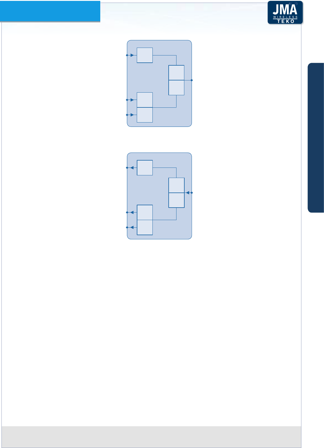
Master Point to Point Module block diagramFigure A18 –
The Slave Point to Point module includes the 4-way splitter/combiner to manage up to 4 Fiber
Optic Transmitter/Receiver Modules. A built-in Supervision unit controls the Slave optical
subrack, hosting the Slave Point to Point module, and all connected Remote Units.
The Coverage System Supervision Module communicates with the Slave Point to Point module
built-in Supervision unit via the single-mode optical ber connecting Master and Slave Point
to Point modules. When Remote optical subracks are equipped with 2 or 3 Slave Point to Point
Modules, only one module communicates with the System Supervision module.
1310nm
DL RF outputs
SMA (f)
connectors
UL RF inputs
SMA (f)
connectors
1550nm
O
E
O
E
Coupler
Att.
WDM Modem
P
DL/UL
optical SC/APC
connector
Att.
Slave Point to Point Module block diagramFigure A19 –
A
B
C
Components & Solutions
Teko DAS Platform Technical Handbook Doc ID Number 91 080 0783 rev. 01 | page A32
TEKO DAS Platform
Master Point to Point Module Access Points
Master Point to Point Module front viewFigure A20 –
Label (Connectors) Description
DL UL Optical input/output SC-APC connector (from/to Slave Point to Point
Module) - laser aperture
RS485 RJ45 connector for RS485 connection to the Supervision Module
DL RF input SMA connector (from the System RF Interface modules)
UL RF output SMA connector (to the System RF Interface modules)
Label (LEDs) Description
ON Master Point to Point Module operating status green LED:
ON when power supply is present
ALM Point to Point Module alarm status LED:
OFF: regular operation
Blinking Orange: presence of active alarms with warning severity level
Orange: presence of active alarms with minor severity level
Blinking Red: presence of active alarms with major severity level
Red: presence of active alarms with critical severity level
DL Fiber Optic Transmitter operating status LED:
BLINKING GREEN: the module is reaching its operating temperature
GREEN optical output power is available
ORANGE: warning: optical output power is degradated
RED: Laser Fault: no optical output power
UL Fiber Optic Receiver operating status LED:
GREEN: +6dBm to -5dBm optical input power
When a Low Optical Power alarm arises in the Fiber Optic receiver the
UL led turns RED and the ALM Led switches on (RED)
A
B
C
Components & Solutions
Teko DAS Platform Technical Handbook Doc ID Number 91 080 0783 rev. 01 | page A33
TEKO DAS Platform
Slave Point to Point Module Access Points
Slave Point to Point Module front viewFigure A21 –
Label (Connectors) Description
DL UL Optical input/output SC-APC connector (from/to Master Point to Point
Module) - laser aperture
RS232 Factory use only
DL RF output SMA connectors (to Fiber Optic Modules)
UL RF input SMA connectors (from Fiber Optic Modules)
Label (LEDs) Description
ON Master Point to Point Module operating status green LED:
ON when power supply is present
ALM
Point to Point Module alarm status LED:
OFF: regular operation
Blinking Orange: presence of active alarms with warning severity level
Orange: presence of active alarms with minor severity level
Blinking Red: presence of active alarms with major severity level
Red: presence of active alarms with critical severity level
DL
Fiber Optic Receiver operating status LED:
GREEN: +6dBm to -5dBm optical input power
When a Low Optical Power alarm arises in the Fiber Optic receiver the
DL led turns RED and the ALM Led switches on (RED)
UL
Fiber Optic Transmitter operating status LED:
BLINKING GREEN: the module is reaching its operating temperature
GREEN optical output power is available
ORANGE: warning: optical output power is degradated
RED: Laser Fault: no optical output power
A
B
C
Components & Solutions
Teko DAS Platform Technical Handbook Doc ID Number 91 080 0783 rev. 01 | page A34
TEKO DAS Platform
Passive Modules providing distribution and lteringA.2.4
Combiner/Splitter Modules•
Combiner/Splitter Modules can be used to manage either up to 4 RF interface modules (POI
modules or TDFE modules), operating in the same band (Multi-Operator Systems) or up to 4
Fiber Optic Transmitter/Receiver Modules.
2-way and 4-way Combiner/Splitter modules are available.
2-way Combiner/Splitter (left), 4-way Combiner/Splitter (right)Figure A22 –
Example: 4-way Combiner/Splitter module block diagrams
4-way combiner (DL side) / 4-way splitter
(UL side) to manage up to 4 RF interface
modules operating in the same band
4-way splitter (DL side) / 4-way combiner
(UL side) to manage up to 4 Fiber Optic
Transmitter/Receiver Modules
RF INTERFACE
MODULES
(POI or DFE)
FIBER OPTIC
MODULES
4WAY
SPLITTER/COMBINER
4WAY
SPLITTER/COMBINER
DL
UL
DL
UL
RF INTERFACE
MODULE
(POI or DFE)
FIBER OPTIC
MODULE
A
B
C
Components & Solutions
Teko DAS Platform Technical Handbook Doc ID Number 91 080 0783 rev. 01 | page A35
TEKO DAS Platform
Combiner/Splitter Modules Access Points
2-way Combiner/Splitter4-way Combiner/Splitter
Label (Connectors) Description
UL
WHEN USED TO MANAGE MULTIPLE
RF INTERFACE MODULES
Up-link path output
SMA connectors (to RF
interface modules)
WHEN USED TO MANAGE MULTIPLE
FIBER OPTIC MODULES
Up-link path input
SMA connectors (from
optical sub-racks)
UL COMMON Up-link path input
SMA connector
Up-link path output
SMA connector
DL Down-link path input
connectors (from RF
interface modules)
Down-link path
output connectors
(to optical sub-racks)
DL COMMON Down-link path
output
Down-link path input
A
B
C
Components & Solutions
Teko DAS Platform Technical Handbook Doc ID Number 91 080 0783 rev. 01 | page A36
TEKO DAS Platform
Triplexer (Band Splitter/Combiner)•
The Triplexer is used in multi-band congurations to distribute signals operating over dierent
bands. Several models of Triplexers, operating over dierent Uplink/Downlink frequency
bands, are available. The triplexer can be equipped with a built-in 4-way Splitter/Combiner.
Triplexers: without built-in 4-way Combiner/Splitter (left), with built-in 4-way Combiner/Splitter Figure A23 –
(right)
The triplexer with built-in 4-way Splitter/Combiner can be used in Optical DAS to manage:
up to 3 RF interface modules operating in dierent bands (and up to 4 Fiber Optic Transmitter/ -
Receiver Modules), or
up to 3 Service Front End modules operating in dierent bands (and up to 4 Fiber Optic -
Transmitter/Receiver Modules), or
up to 3 four-way splitter/combiner - used to manage multiple RF interface modules- up to -
4 for each band (and up to 4 Fiber Optic Transmitter/Receiver Modules).
A
B
C
Components & Solutions
Teko DAS Platform Technical Handbook Doc ID Number 91 080 0783 rev. 01 | page A37
TEKO DAS Platform
DL
ATT.
BAND 1
f < 1GHz
BAND 2
f > 1GHz
BAND 3
f > 1GHz
LOW
HIGH
HIGH
HIGH
Example: 1-Low-band + 2-High-Band Triplexer block diagram (Downlink path)Figure A24 –
UL
ATT.
BAND 1
f < 1GHz
BAND 2
f > 1GHz
BAND 3
f > 1GHz
LOW
HIGH
HIGH
HIGH
Example: 1-Low-band + 2-High-Band Triplexer block diagram (Uplink path)Figure A25 –
A
B
C
Components & Solutions
Teko DAS Platform Technical Handbook Doc ID Number 91 080 0783 rev. 01 | page A38
TEKO DAS Platform
Triplexer Module Access Points -Example
Triplexer with built-in 4-way
Combiner/Splitter
Triplexer without built-in
4-way Combiner/Splitter
BAND 1
BAND 2
BAND 3
BAND 1
BAND 2
BAND 3
Connectors Description
BAND 1 BAND 1 input (down-link path)
BAND 1 output (up-link path)
BAND 2 BAND 2 input (down-link path)
BAND 2 output (up-link path)
BAND 3 BAND 3 input (down-link path)
BAND 3 output (up-link path)
UL
COMMON
WHEN USED TO MANAGE
MULTIPLE FIBER OPTIC
MODULES
Uplink path input
connectors (from
optical subrack)
WHEN USED TO MANAGE
MULTIPLE FOUR-WAY
COMBINER/SPLITTER MODULES
Uplink path output
connectors (to 4-way
combiner/splitter
modules)
DL
COMMON
Downlink path
output connectors
(to optical subrack)
Downlink path input
connectors (from
4-way combiner/
splitter modules)
A
B
C
Components & Solutions
Teko DAS Platform Technical Handbook Doc ID Number 91 080 0783 rev. 01 | page A39
TEKO DAS Platform
Esaplexer (US bands)•
The Esaplexer is used in multi-band congurations to distribute signals operating over up to
6 dierent bands.
The Esaplexer can be connected to a 4-way splitter/combiner in order to manage up to 4 Fiber
Optic Transmitter/Receiver Modules (i.e. up to 16 Remote Units).
BAND 1
BAND 4
DL OUT
BAND 1
BAND 4
BAND 6BAND 6
HI
BAND 2 +
BAND 3
BAND 2
+
BAND 3
BAND 5BAND 5
LO
To a single optical module or
to the 4-way splitter-combiner
for the management of up to 4
optical modules
From the optical module or from
the 4-way splitter-combiner used
for the management of up to 4
optical modules
BAND 1
BAND 4
UL IN
BAND 1
BAND 4
BAND 6BAND 6
HI
BAND 2 +
BAND 3
BAND 2
+
BAND 3
BAND 5BAND 5
LO
Example: 4-Low-band + 2-High-Band Esaplexer block diagramFigure A26 –
A
B
C
Components & Solutions

Teko DAS Platform Technical Handbook Doc ID Number 91 080 0783 rev. 01 | page A40
TEKO DAS Platform
Esaplexer Access Points•
DL path UL path
Band (or
Bands) 1
Band (or
Bands) 2
Band (or
Bands) 5
Band or
Bands 2
Band (or
Bands) 5
Band (or
Bands) 3
Band (or
Bands) 4
Label Description
DL OUT Downlink path output connector
UL IN Uplink path input connector
Band (or Bands) 1 Band (or Bands) 1 input (downlink path)
Band (or Bands) 1 output (uplink path)
Band (or Bands) 2 Band (or Bands) 2 input (downlink path)
Band (or Bands) 2 output (uplink path)
Band (or Bands) 3 Band (or Bands) 3 input (downlink path)
Band (or Bands) 3 output (uplink path)
Band (or Bands) 4 Band (or Bands) 4 input (downlink path)
Band (or Bands) 4 output (uplink path)
Band (or Bands) 5 Band (or Bands) 5 input (downlink path)
Band (or Bands) 5 output (uplink path)
A
B
C
Components & Solutions
Teko DAS Platform Technical Handbook Doc ID Number 91 080 0783 rev. 01 | page A41
TEKO DAS Platform
Pentaplexer•
The Pentaplexer is used in multi-band congurations to distribute signals operating over up
to 5 dierent bands.
The Pentaplexer can be connected to a 4-way splitter/combiner in order to manage up to 4
Fiber Optic Transmitter/Receiver Modules (i.e. up to 16 Remote Units).
BAND 1
BAND 3
DL OUT
BAND 1
BAND 3
BAND 5BAND 5
HI
BAND 2
BAND 2
BAND 2
BAND 4BAND 4
LO
To a single optical module or
to the 4-way splitter-combiner
for the management of up to 4
optical modules
From the optical module or from
the 4-way splitter-combiner used
for the management of up to 4
optical modules
BAND 1
BAND 3
UL IN
BAND 1
BAND 3
BAND 5BAND 5
HI
BAND 4BAND 4
LO
BAND 2
3-Low-band- + 2-High-Band Pentaplexer block diagramFigure A27 –
A
B
C
Components & Solutions
Teko DAS Platform Technical Handbook Doc ID Number 91 080 0783 rev. 01 | page A42
TEKO DAS Platform
Pentaplexer Access Points•
DL path UL path
Band 1
Band 2
Band 5
Band 2
Band 5
Band 3
Band 4
Label Description
DL OUT Downlink path output connector
UL IN Uplink path input connector
Band 1 Band 1 input (downlink path)
Band 1 output (uplink path)
Band 2 Band 2 input (downlink path)
Band 2 output (uplink path)
Band 3 Band 3 input (downlink path)
Band 3 output (uplink path)
Band 4 Band 4 input (downlink path)
Band 4 output (uplink path)
Band 5 Band 5 input (downlink path)
Band 5 output (uplink path)
A
B
C
Components & Solutions
Teko DAS Platform Technical Handbook Doc ID Number 91 080 0783 rev. 01 | page A43
TEKO DAS Platform
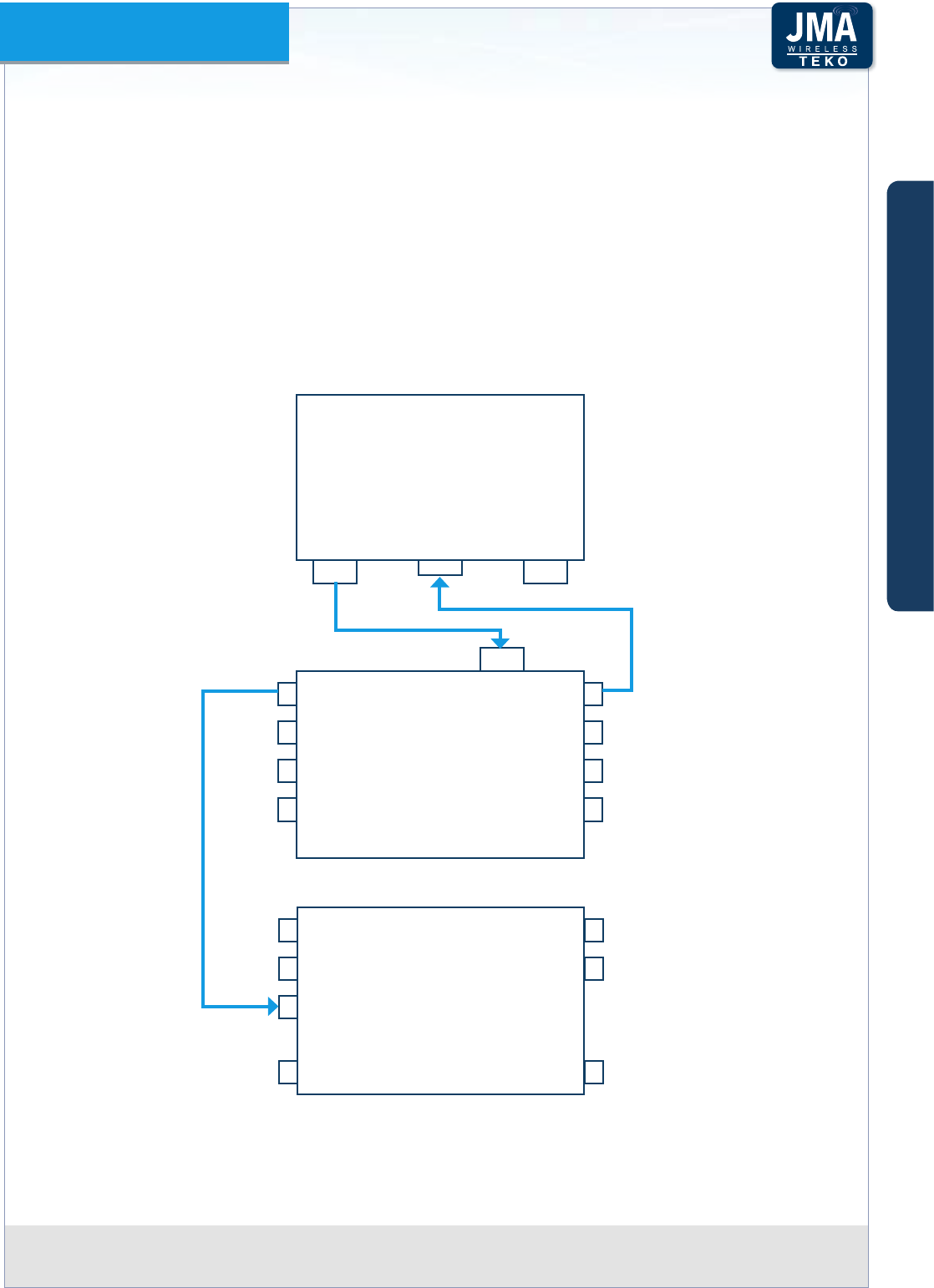
Master Unit Components for Time Division LTE (LTE-TDD) technologyA.2.5
The Teko DAS Platform integrates Time-Division Long-Term Evolution technology and provides
a full set of components dedicated to the LTE-TDD:
TSYNC, TDD synchronizer module managing and distributing the BS TDD reference Signals;•
TDD DAS Tray Point of Interface, geared to pick up the TDD reference signals from BS;•
Triplexer combining the FDD/TDD bands for distribution and • synchronizing the downstream
DAS components.
Teko 2-way and 4-way Combiner/Splitter modules (TSC2W-U and TSC4W-U) are TDD Ready
and can be deployed directly in TDD Systems.
TSYNC
TDD synchronizer
Triplexer for
FDD/TDD bands combination •
and distribution
downstream DAS components •
synchronization
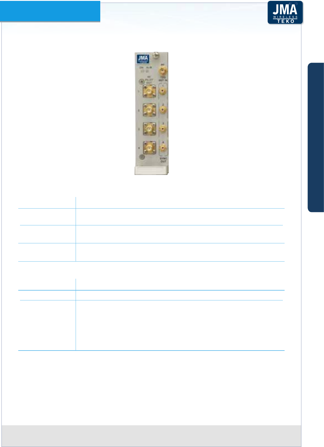
TDD DAS Tray
Point of Interface
TDD
SYNC IN
RF TDD REF IN
RF BS A
monitor
RF BS B
monitor
RF PILOT
OUT
SYNC
OUT
1 1
2 2
3 3
4 4
SYNC IN
DL
COMMON
UL
COMMON
UL
BAND 1
DL
BAND 1
UL
BAND 2
DL
BAND 2
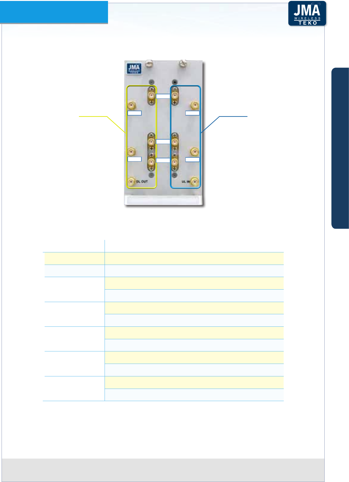
Synchronizing signal pathFigure A28 –
A
B
C
Components & Solutions
Teko DAS Platform Technical Handbook Doc ID Number 91 080 0783 rev. 01 | page A44
TEKO DAS Platform
TSYNC Access Points•
TSYNC front viewFigure A29 –
Label (Connectors) Description
RF
TDD REF IN
RF BS signal input
SYNC OUT
(1 to 4)
BS TDD reference signal output connector (MCX type) to TDD DAS Tray
Point of Interface for module synchronization
RF PILOT OUT
(1 to 4)
BS TDD reference signal output connector (SMA-F type) to the
Triplexer
Label (LEDs) Description
ON Module operating status green LED: ON when power supply is present
ALM
TSYNC Module alarm status LED:
OFF: regular operation
Blinking Orange: presence of active alarms with warning severity level
Orange: presence of active alarms with minor severity level
Blinking Red: presence of active alarms with major severity level
Red: presence of active alarms with critical severity level
A
B
C
Components & Solutions
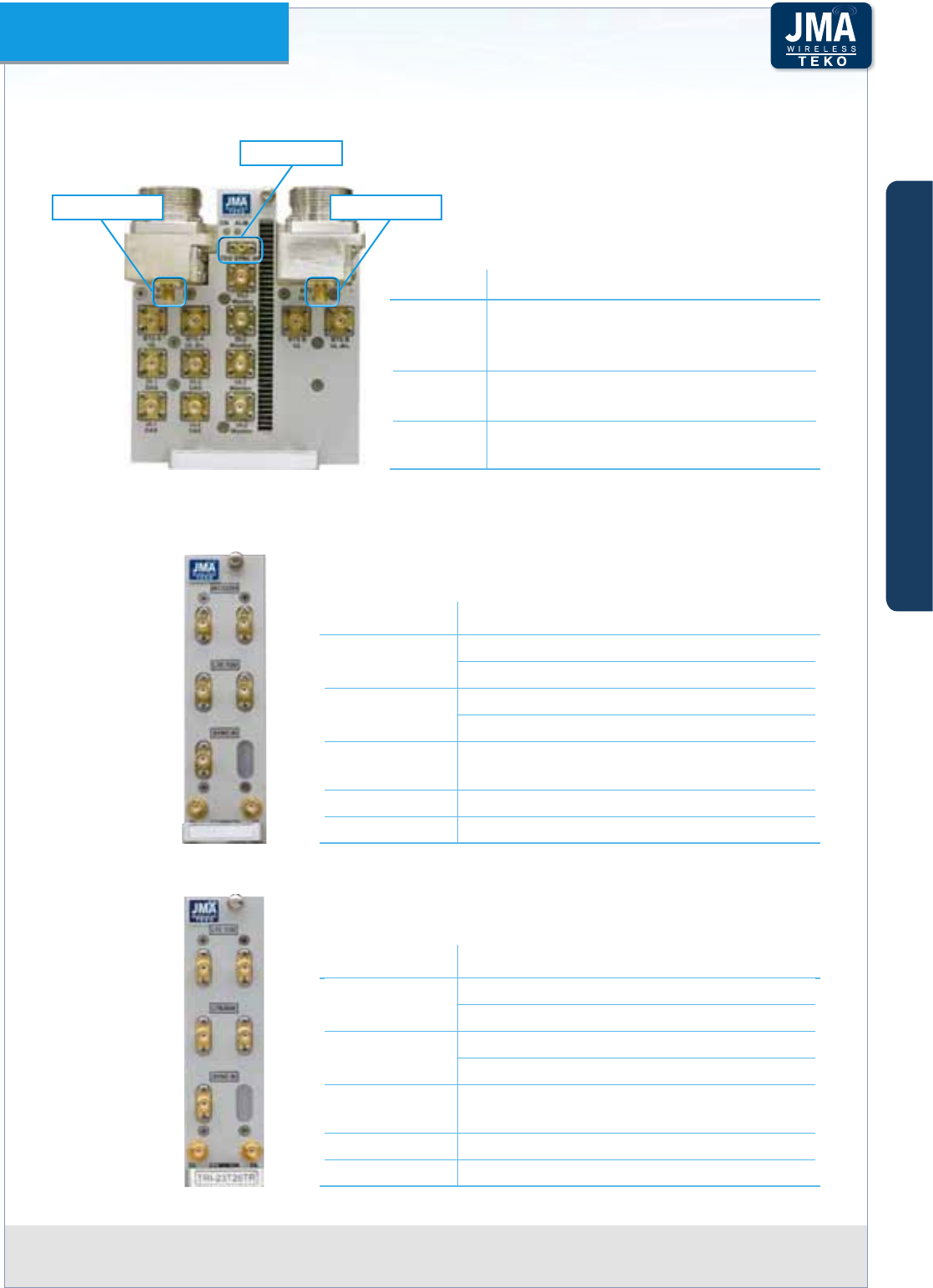
Teko DAS Platform Technical Handbook Doc ID Number 91 080 0783 rev. 01 | page A45
TEKO DAS Platform
TDD DAS Tray Point of Interface - Additional Access Points•
Connector Description
TDD SYNC
IN
Base Station TDD reference signal input
connector (MCX type)
from the TDD synchronizer module
BTS A
monitor
Monitor port - to the TDD synch module,
extracting the BS TDD reference signal
BTS B
monitor
Monitor port - to the TDD synch module,
extracting the BS TDD reference signal
BTS B monitorBTS A monitor
TDD SYNC IN
FDD/TDD Triplexer Access Points•
TRI-2325TR
Ì
Connector Description
WCS2300 WCS2300 input (down-link path)
WCS2300 output (up-link path)
LTE TDD LTE TDD input (down-link path)
LTE TDD output (up-link path)
SYNC IN BTS TDD reference signal input (from
TSYNC)
DL COMMON Downlink path output connector
UL COMMON Uplink path input connector
TRI-23T26TR Ì
Connector Description
LTE TDD LTE TDD input (down-link path)
LTE TDD output (up-link path)
LTE2600 LTE2600 input (down-link path)
LTE2600 output (up-link path)
SYNC IN BTS TDD reference signal input (from
TSYNC)
DL COMMON Downlink path output connector
UL COMMON Uplink path input connector
A
B
C
Components & Solutions
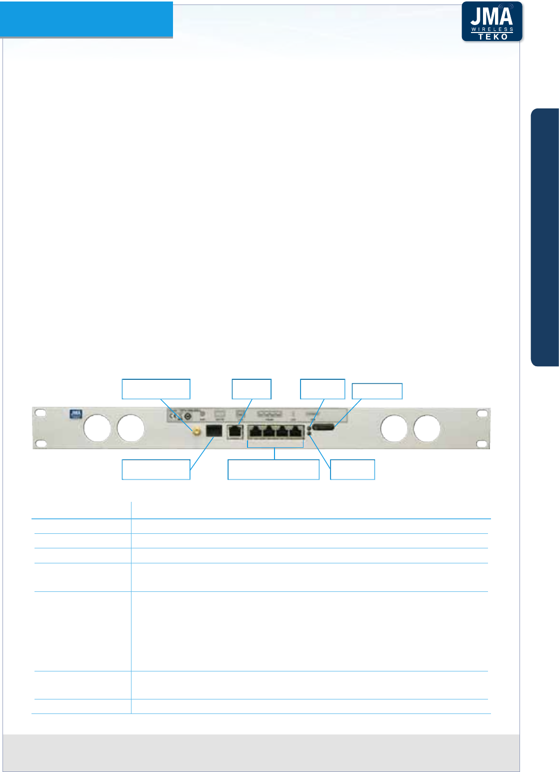
Teko DAS Platform Technical Handbook Doc ID Number 91 080 0783 rev. 01 | page A46
TEKO DAS Platform
Components for the management of the SystemA.2.6
Supervision Units•
A single Supervision Unit allows the management of the entire System utilizing secure browser
technology that enables administration from any location.
The Teko Supervision unit provides web-based administration and SNMP v3 support with
Event-based Congurations that signicantly simplify remote administration (web browser,
tablets) and enables integration with SNMP v3 Management tools.
For remote control the System can be accessed via optional wireless modem (integrated
inside the supervision module).
JMA Wireless Teko OMT (Operation and Maintenance Terminal) web pages allow the
commissioning, monitoring, setting and troubleshooting of the whole Coverage and Capacity
System via a user friendly graphical interface.
Teko OMC (Operation Management Centre) proprietary software is available to control multiple
Supervision Modules managing dierent Coverage and Capacity Systems in a Network.
Rack-mount Light Supervision shelf - Access Points Ì
A Light Supervision module, compact and powerful, is available for the management of up to
4 sub-racks: it is suitable for modular repeaters or small/medium DAS.
SMA connector for
external antenna LAN port
4 dry contacts for
external alarms
SIM card slot
Alarm
status LED
Operating
status LED
4 RS485 ports to connect
4 dierent sub-racks
Rack mount Light Supervision shelf front viewFigure A30 –
Label (Connectors) Description
ANT Optional built-in wireless modem antenna SMA connector
EXT IN External alarms input connector
LAN Local Control Interface (RJ45 connector)
RS485
(1 to4)
RJ45 connectors for the management of monitored Active Subracks,
mounted within the same rack cabinet hosting the Supervision module
LED Supervision Module alarm status LED.
OFF: regular operation
Blinking Orange: presence of active alarms with warning severity level
Orange: presence of active alarms with minor severity level
Blinking Red: presence of active alarms with major severity level
Red: presence of active alarms with critical severity level Supervision
LED Module operating status green LED:
ON when power supply is present
SIM Optional built-in modem SIM card slot
A
B
C
Components & Solutions
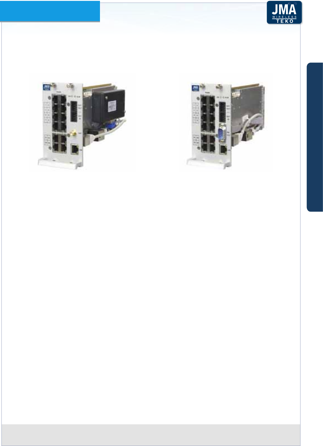
Teko DAS Platform Technical Handbook Doc ID Number 91 080 0783 rev. 01 | page A47
TEKO DAS Platform
Supervision Module Ì
A Supervision module is available for the management of more sophisticated Teko DAS
architectures: the supervision module allows the management of up to 13 Active Subracks.
Supervision Module: equipped with optional built-in wireless modem (left), without built-in Figure A31 –
wireless modem (right)
When the optional built-in wireless modem is equipped, an SMA input/output connector is
available on the Supervision front panel for remote management.
4 external alarm inputs and 4 dry contact outputs are available on the Supervision module
front panel.
The 4 Input lines are opto-isolated and are activated by a short circuit between input pins
(max current ow during short = 6mA; max Vdc at input pins = 3.3V).
Please refer to Paragraph B.4.4 for details about external alarms connections.
A
B
C
Components & Solutions
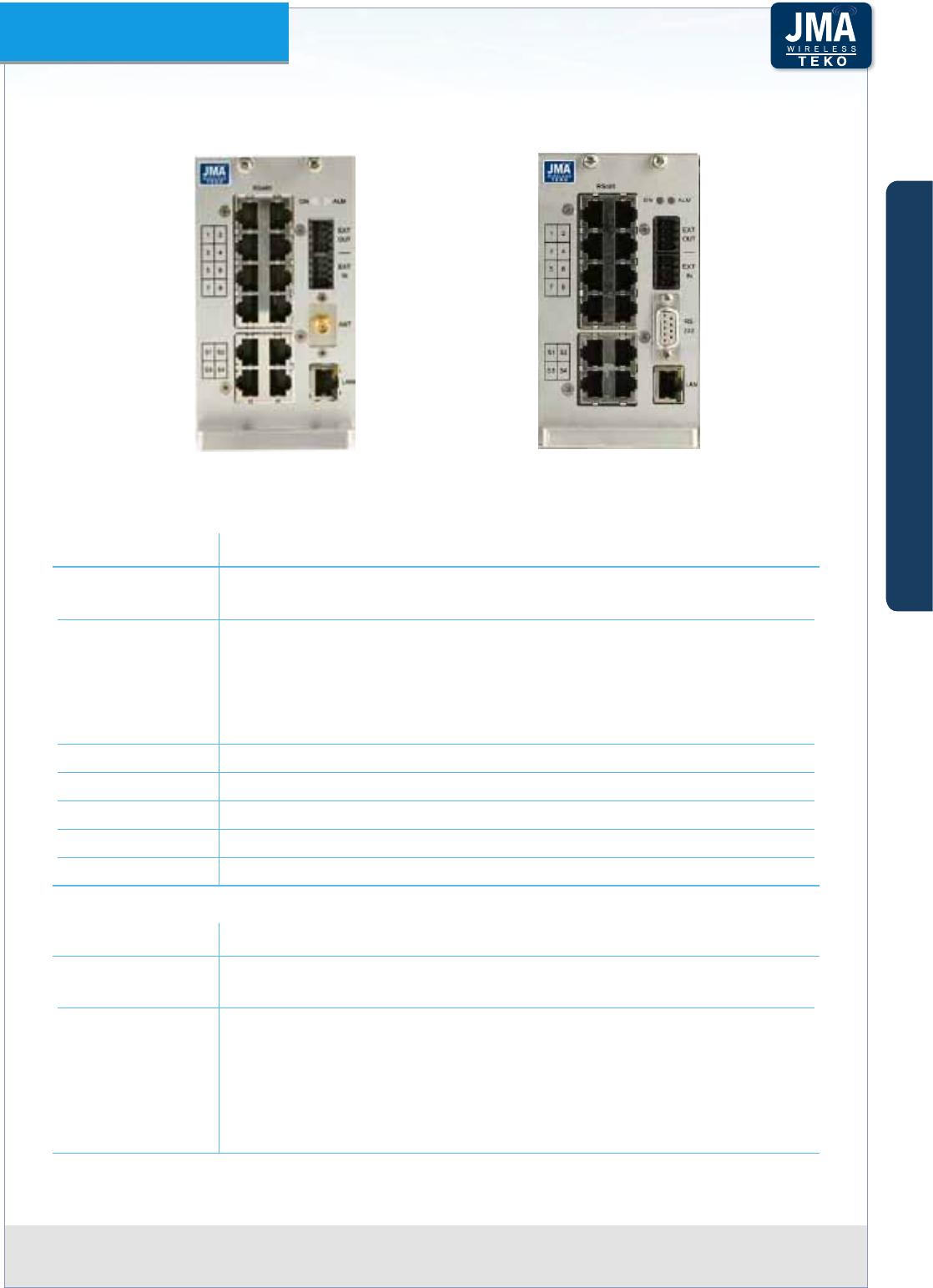
Teko DAS Platform Technical Handbook Doc ID Number 91 080 0783 rev. 01 | page A48
TEKO DAS Platform
Supervision Module Access Points
Supervision Module equipped with
optional built-in wireless modem
Supervision Module without
built-in wireless modem
Label (Connectors) Description
RS485
(1 to 8)
RJ45 connectors for the management of monitored Active Subracks,
mounted within the same rack cabinet hosting the Supervision module
RS485
(S1 to S4)
RJ45 connectors for the management of remote Active Subracks
equipped with Point to Point slave modules.
When not connected to remote Subracks, these ports can be used to
manage additional Active Subracks (exceeding 8) mounted within the
same rack cabinet hosting the Supervision module
EXT OUT External alarms output connector
EXT IN External alarms input connector
RS232 Factory use only
ANT Optional built-in wireless modem antenna SMA connector
LAN RJ45 connector Local Control Interface
Label (LEDs) Description
ON Supervision Module operating status green LED:
ON when power supply is present
ALM
Supervision Module alarm status LED.
OFF: regular operation
Blinking Orange: presence of active alarms with warning severity level
Orange: presence of active alarms with minor severity level
Blinking Red: presence of active alarms with major severity level
Red: presence of active alarms with critical severity level
A
B
C
Components & Solutions

Teko DAS Platform Technical Handbook Doc ID Number 91 080 0783 rev. 01 | page A49
TEKO DAS Platform
Alarm Board•
The Alarm Board is an optional I/O Module that can be equipped in addition to the Supervision
Module, in order to increase the number of supported external alarms.
Alarm Board equipped with 16 input pins - TEA-I16Figure A32 –
16 external alarm inputs are available on the Alarm Board front panel.
The 16 Input lines are opto-isolated and are activated by a short circuit between input pins
(max current ow during short = 6mA; max Vdc at input pins = 3,3V).
Inputs 1-to-4 can be switched to dry output contacts upon request.
Please refer to the Supervision Module external alarms connection (Paragraph B.4.4) for details
about external alarms connections.
A
B
C
Components & Solutions

Teko DAS Platform Technical Handbook Doc ID Number 91 080 0783 rev. 01 | page A50
TEKO DAS Platform
Alarm Board Access Points
Alarm Board
with female dry connectors
Alarm Board
without female dry connectors
Label (Connectors) Description
EXT IN External alarms input connector
EXT OUT Optional external alarms output connector (TEA-I12O4)
Label (LEDs) Description
ON Alarm Board Module operating status green LED:
ON when power supply is present
ALM
Alarm Board Module alarm status LED.
OFF: regular operation
Blinking Orange: presence of active alarms with warning severity level
Orange: presence of active alarms with minor severity level
Blinking Red: presence of active alarms with major severity level
Red: presence of active alarms with critical severity level
A
B
C
Components & Solutions
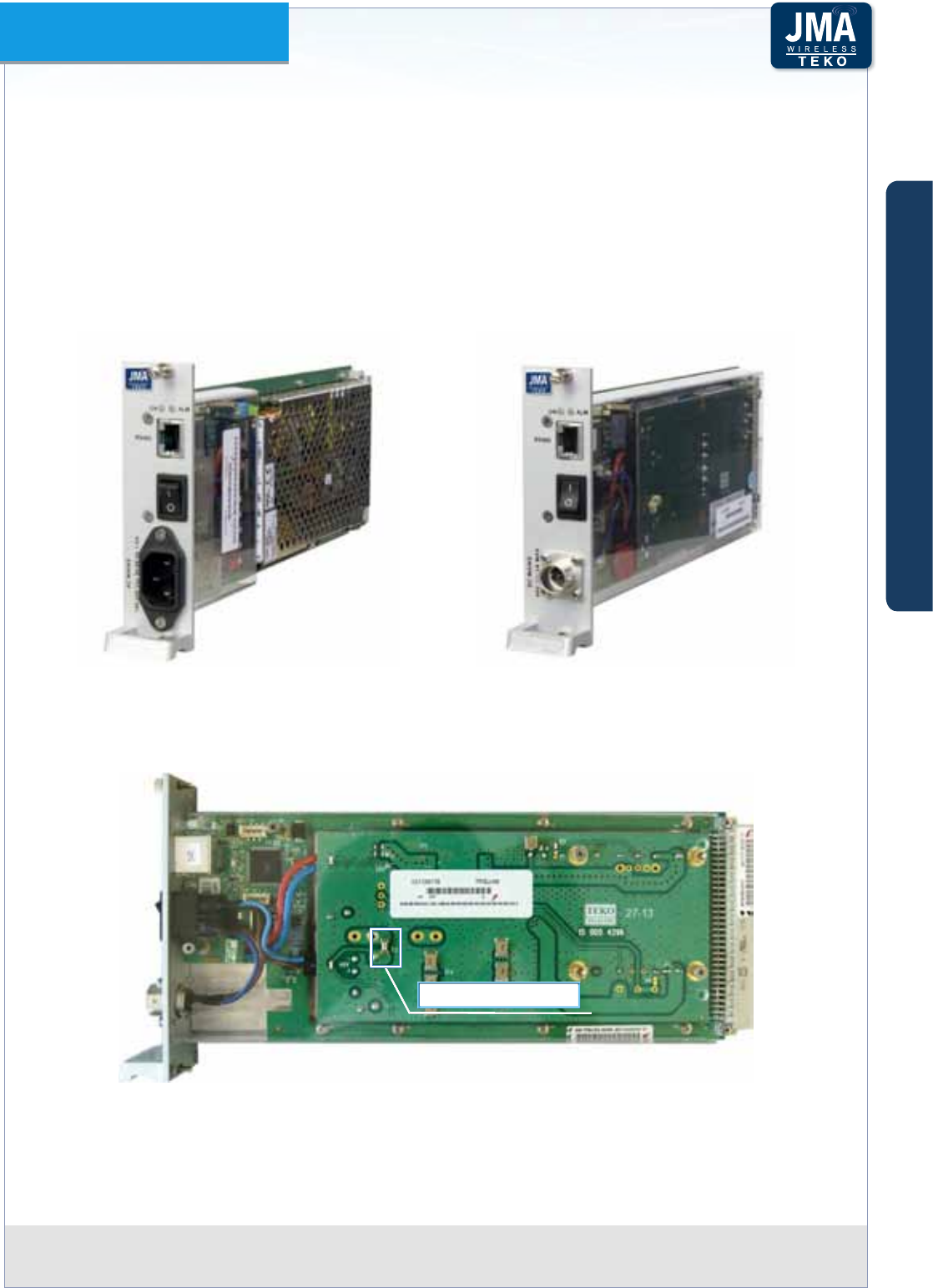
Teko DAS Platform Technical Handbook Doc ID Number 91 080 0783 rev. 01 | page A51
TEKO DAS Platform
A.2.7 Power Supply Components
Power Supply Modules (TPSU)•
Power Supply modules are either AC-to-DC or DC-to-DC plug-in modules that provide power
to Active Subracks. Each module provides up to 100W output power; several modules can
be connected in parallel (please refer to the Teko DAS Platform datasheet for details about
derating factors). Hot-plug 1+1 Redundancy feature is supported: it can be implemented to
achieve high system reliability.
Power Supply Modules: TPSU/AC (left), TPSU/48 (right)Figure A33 –
The following gure shows the DC/DC Power Supply Module protection fuse position and
electrical rating. If the fuse blows, it has to be replaced.
Fuse SMD F10A, 125V
DC/DC Power Supply Module protection fuse position and electrical ratingFigure A34 –
Power Supply modules can be equipped in monitored Active Subracks, in the Master Active
Subrack or in a dedicated Active Subrack.
A
B
C
Components & Solutions
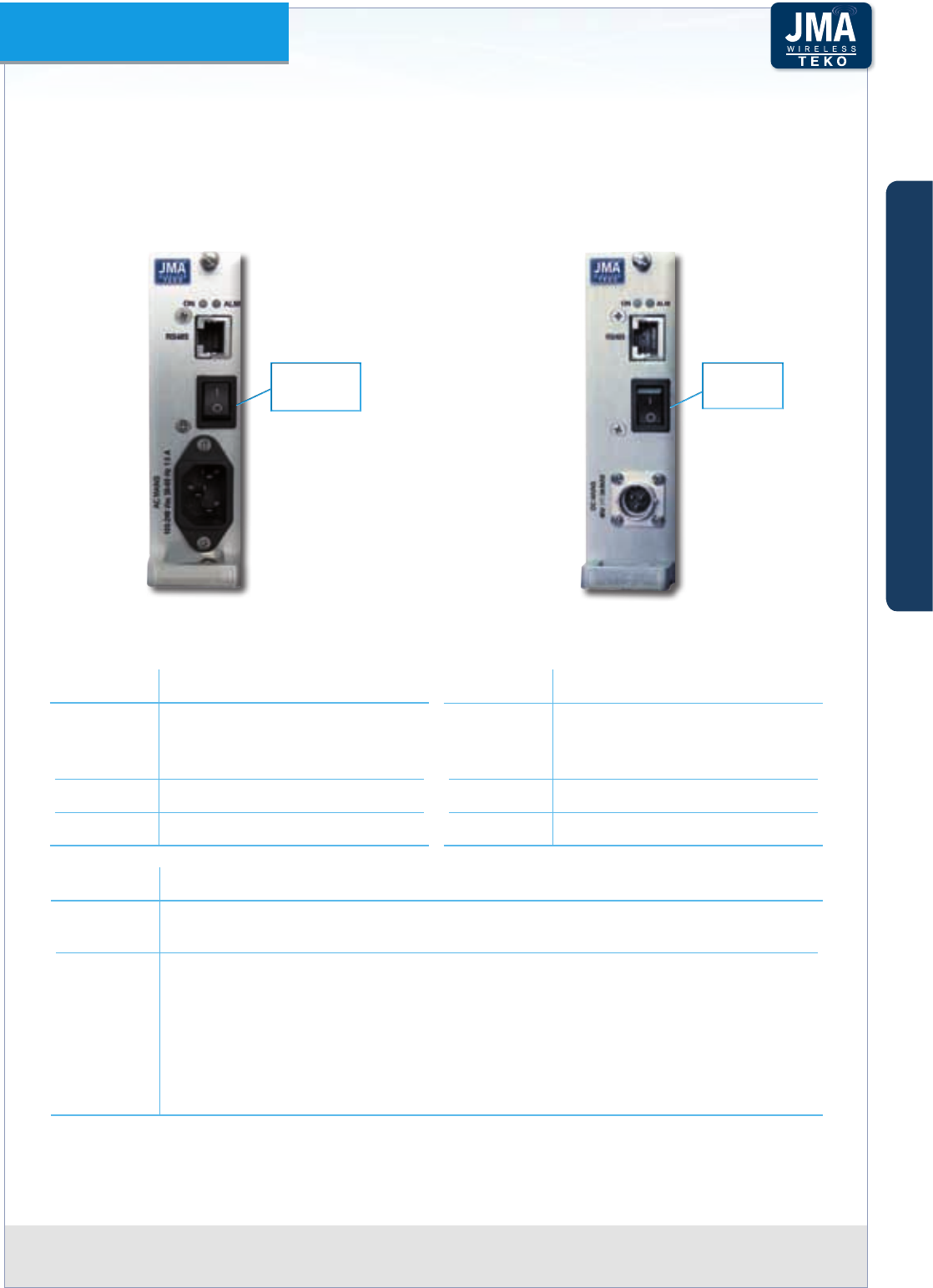
Teko DAS Platform Technical Handbook Doc ID Number 91 080 0783 rev. 01 | page A52
TEKO DAS Platform
When Power Supply modules are equipped in monitored Active Subracks, the RJ45 connector
available on the Power Supply Module front panel can be used for connection to the
Supervision Module, equipped in the Master Active Subrack.
Power Supply Modules Access Points
TPSU/AC
AC/DC Power Supply Module
TPSU/48
DC/DC Power Supply Module
DC switch
AC MAINS
switch
Connectors Description
RS485 RJ45 connector for RS485
connection to the Supervision
Module (monitored Subracks)
AC switch AC MAINS switch
AC MAINS AC MAINS socket (100-240Vac)
Connectors Description
RS485 RJ45 connector for RS485
connection to the Supervision
Module (monitored Subracks)
DC switch 48Vdc switch
DC MAINS Vdc input connector (48Vdc)
Label (LEDs) Description
POWER ON Power Supply Module operating status green LED:
ON when power supply is present
ALM Power Supply Module alarm status LED.
OFF: regular operation
Blinking Orange: presence of active alarms with warning severity level
Orange: presence of active alarms with minor severity level
Blinking Red: presence of active alarms with major severity level
Red: presence of active alarms with critical severity level
A
B
C
Components & Solutions
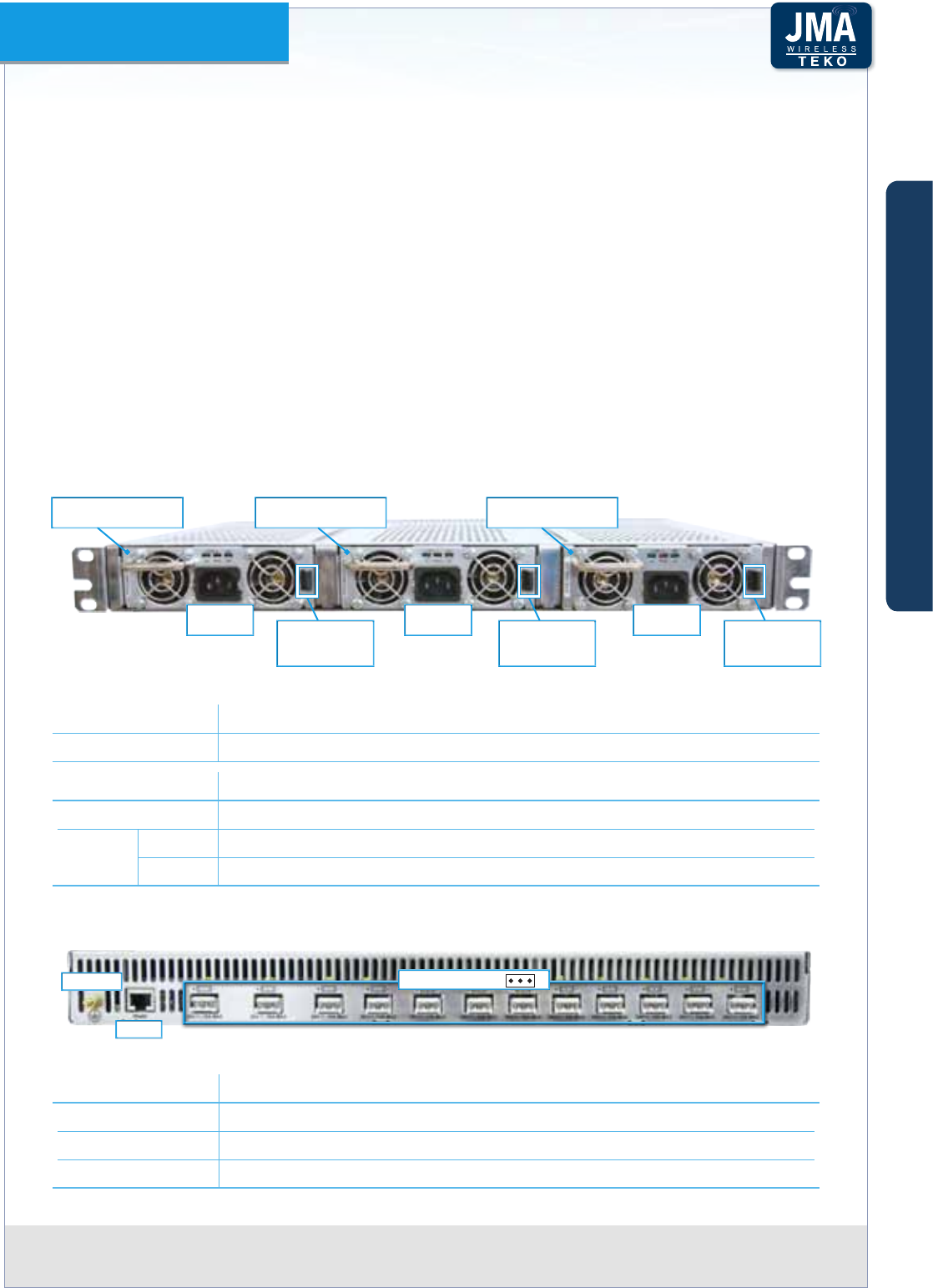
Teko DAS Platform Technical Handbook Doc ID Number 91 080 0783 rev. 01 | page A53
TEKO DAS Platform
Power Supply Subracks•
The AC-to-DC and DC-to-DC Power Supply subracks allow a reduction in the amount of
space required for the System installation: they can be equipped with up to 3 Power Supply
modules to provide up to 2.4kW (SUB-PSU-MU)/3kW (SUB-PSU-MU/48) output power in just
one height unit space. Hot-plug 1+1 redundancy feature is supported: load-sharing power
supply modules can be installed to achieve high system reliability. Hot-plugging allows a
faulty power supply module to be replaced without powering o the system.
The power supply subracks allow the reset of the whole Master Unit, or PTP Slave subrack,
from the System management software (OMT webpages / OMC proprietary software).
SUB-PSU-MU: the AC-to-DC Power Supply Subrack
Ìcan be equipped with up to 3 AC/DC
Power Supply modules to provide up to 2.4kW output power.
Front Access Points
900W POWER SUPPLY
MODULE
900W POWER SUPPLY
MODULE
900W POWER SUPPLY
MODULE
AC MAINS
socket Power Supply
Module Locking
Tab
Power Supply
Module Locking
Tab
Power Supply
Module Locking
Tab
AC MAINS
socket
AC MAINS
socket
SUB-PSU-MU Power Supply subrack (maximum conguration 2.4kW output power) - Front viewFigure A35 –
Connectors Description
AC MAINS AC MAINS socket (100-240Vac)
Label (LEDs) Description
AC ON (green) when AC input is present
DC OK ON (green) when DC output is available
FAIL ON (RED) when DC output is unavailable
Rear Access Points
RS 485
GROUND Vdc OUTPUTS + -
SUB-PSU-MU Power Supply subrack - Rear viewFigure A36 –
Connectors Description
GROUND Equipment grounding
RS485 RJ45 connector for RS485 connection to the Supervision Module
Vdc outputs 28Vdc Outputs (max 10A each)
A
B
C
Components & Solutions
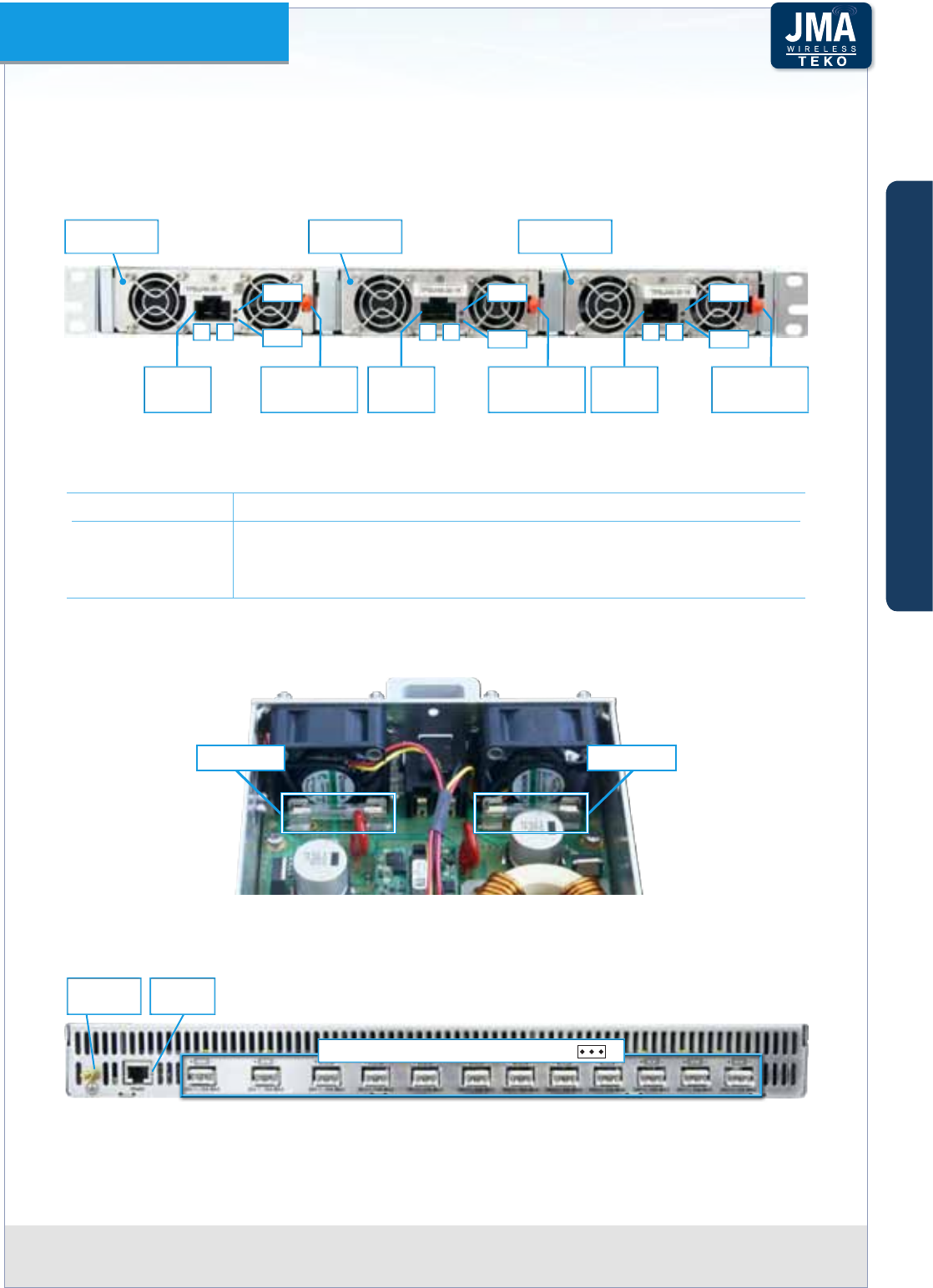
Teko DAS Platform Technical Handbook Doc ID Number 91 080 0783 rev. 01 | page A54
TEKO DAS Platform
SUB-PSU-MU/48 : the DC-to-DC Power Supply Subrack Ìcan be equipped with up to 3 DC/
DC Power Supply modules to provide up to 3kW output power.
Front Access Points
1kW Power
Supply Module
+ + +– – –
1kW Power
Supply Module
1kW Power
Supply Module
Vdc input
connector
(48Vdc)
Vdc input
connector
(48Vdc)
Vdc input
connector
(48Vdc)
Power Supply
Module Locking
Tab
Power Supply
Module Locking
Tab
Power Supply
Module Locking
Tab
LED 1 LED 1 LED 1
LED 2 LED 2 LED 2
SUB-PSU-MU/48Figure A37 – Power Supply subrack (maximum conguration 3kW output power) - Front view
LEDs Description
LED 1 ON (green) when DC input is present
LED 2 OFF: regular operation
ORANGE: fan fail alarm
RED: DC output voltage alarm or communication alarm
Please note
Each DC input is protected by fuses:
F20A, 250V F20A, 250V
DC/DC Power Supply module (TPSU/48-30-1K) input protection fuses position and electrical ratingFigure A38 –
Rear Access Points
Vdc Outputs 28Vdc (max 10A each) + -
Equipment
Grounding
RJ45
connector
SUB-PSU-MU/48 Power Supply subrack - Rear viewFigure A39 –
A
B
C
Components & Solutions
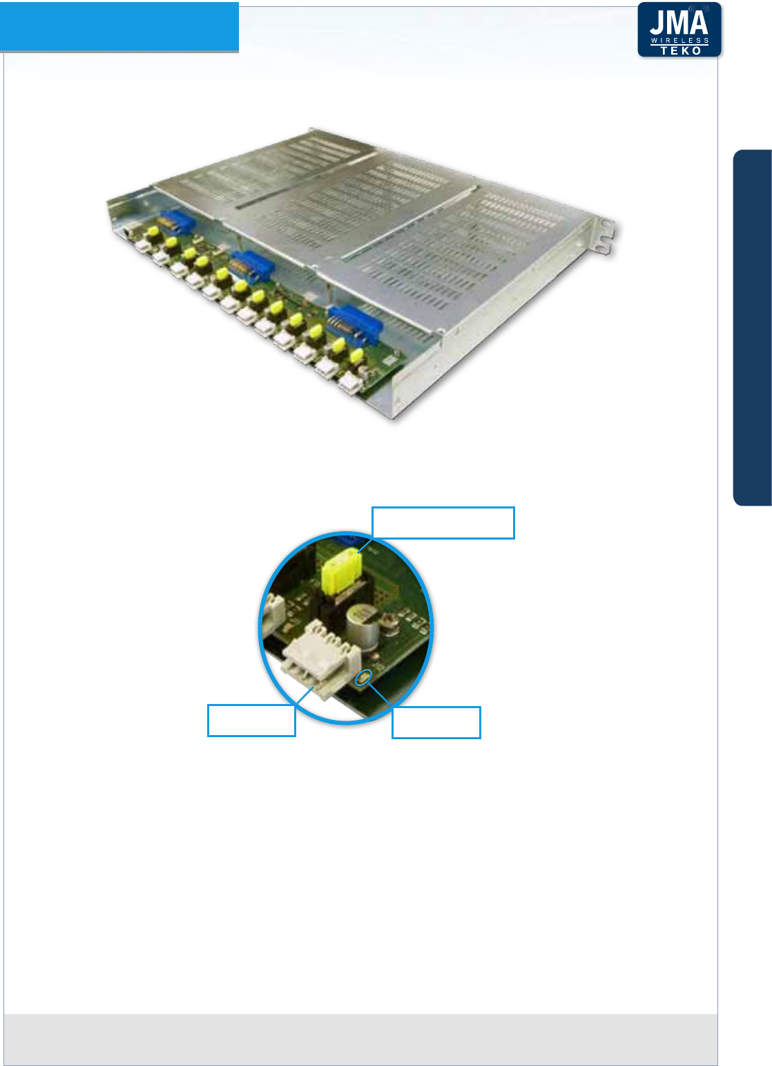
Teko DAS Platform Technical Handbook Doc ID Number 91 080 0783 rev. 01 | page A55
TEKO DAS Platform
SUB-PSU-MU and SUB-PSU-MU/48: Ìeach Vdc output connector is protected by a fuse.
SUB-PSU-MU and SUB-PSU-MU/48 protection fuses positionFigure A40 –
If a fuse blows, the management software reports an Output Voltage alarm for the connector
involved and the green led to the right of the connector switches o. The fuse has to be
replaced. Connector n protection
fuse (32V-20A)
Connector n
operating LED
28Vdc output
connector (n)
Detail: Connector n protection fuse and operating status ledFigure A41 –
Please note
DC/DC Power Supply modules (TPSU/48-30-1K) can be equipped in the SUB-PSU-MU/48
subrack only.
AC/DC Power Supply modules (TPSU/AC-30-1K) can be equipped in the SUB-PSU-MU subrack
only.
A
B
C
Components & Solutions
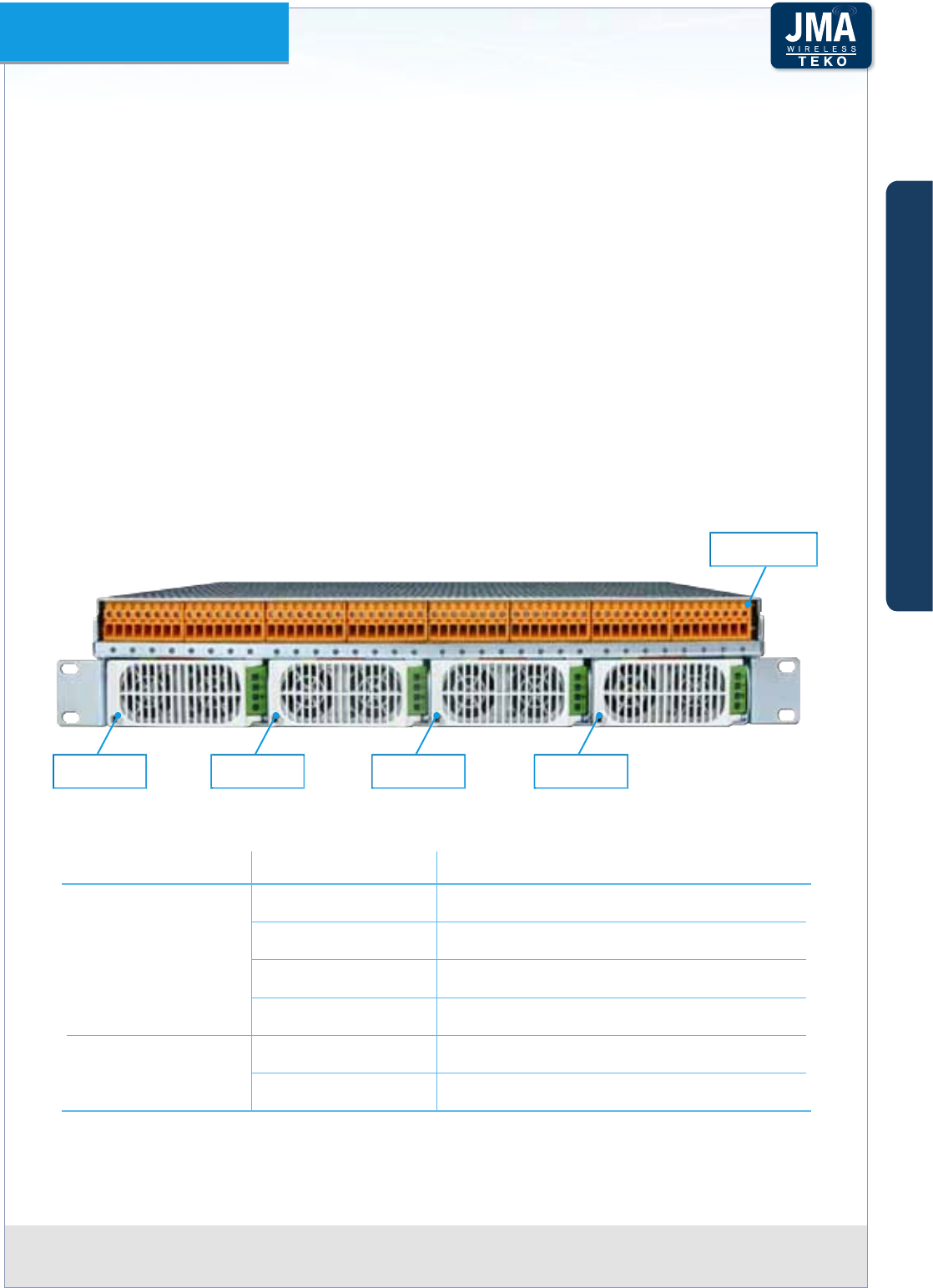
Teko DAS Platform Technical Handbook Doc ID Number 91 080 0783 rev. 01 | page A56
TEKO DAS Platform
Power Supply distribution system•
A centralized Power Supply distribution solution is available for the remote powering of Teko
48VDC Low Power Remote Units.
The Power Supply distribution system is composed of both a Power Supply Unit (PSU) and a
Power Distribution Unit (PDU), housed in a 2U - 19” subrack. The power supply unit can host
up to 4 current-sharing Power Supply modules (either AC/DC or DC/DC).
The conguration allows hot-swapping and supports N+1 redundancy congurations.
The voltage from the power supply modules is made available to the 32 DC power output
ports on the distribution unit front panel.
A Class 2 DC Distribution Unit version is available to meet the requirements of the US National
Electrical Code (NEC).
Please note
Class 2 distribution systems allow power supply cables to be installed throughout the building
without the need of a conduit.
Power Supply
Module 1
Power Supply
Module 3
Power Supply
Module 2
Power Supply
Module 4
Power
Distribution Unit
Power Supply distribution system - Front viewFigure A42 –
Component Commercial code Description
Power Distribution
Unit (PDU)
SUB-RPSU2-MU/AC Class 2 DC Distribution Unit and Subrack
SUB-RPSU2-MU/48 Class 2 DC Distribution Unit and Subrack
SUB-RPSU-MU/AC Standard DC Distribution Unit and Subrack
SUB-RPSU-MU/48 Standard DC Distribution Unit and Subrack
Power supply
modules (1 to 4)
TRPSU/AC-58-1.2K AC/DC power supply module
TRPSU/48-58-2K DC/DC power supply module
Power Supply distribution system components
A
B
C
Components & Solutions
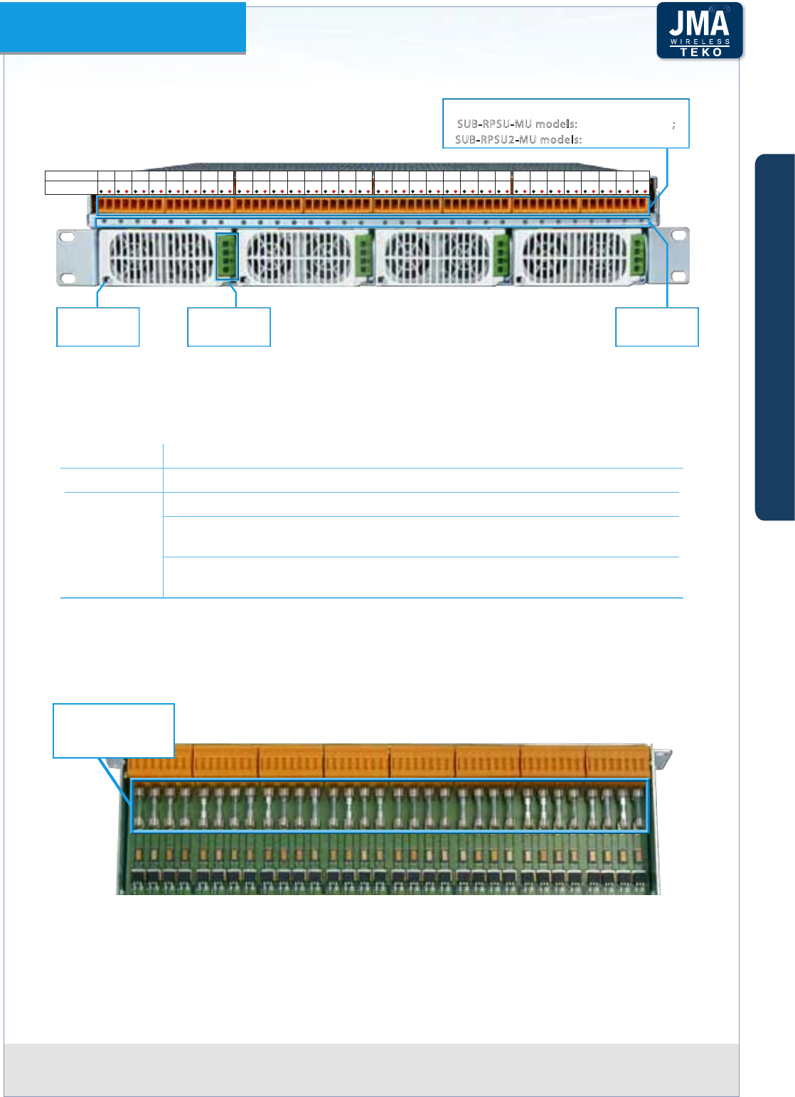
Teko DAS Platform Technical Handbook Doc ID Number 91 080 0783 rev. 01 | page A57
TEKO DAS Platform
Power Supply
Module
securing clip
Power Supply
Module LEDs
Vdc output ports 58Vdc
SUB-RPSU-MU models: max 4.5A each port;
SUB-RPSU2-MU models: max 2.5A each port
Output ports
status LEDs
5 6 7 81
Port number 2 3 41 2 3 5 6 7 84
Port number
1 2 3
Lead polarity
-+
-+-+-+-+-+-+-+
19 10 11 12 13 14 15 16
1 2 3
-+
-+-+-+-+-+-+-+
117 18 19 20 21 22 23 24
1 2 3
-+
-+-+-+-+-+-+-+
125 26 27 28 29 30 31 32
1 2 3
-+
-+-+-+-+-+-+-+
Power Supply distribution system - Front view - Access pointsFigure A43 –
32 LED indicators on the front panel of the Power Distribution unit show the status of each
output port as follows:
Led status Description
OFF Switched o port
ON
Green: regular functioning (normal operation)
Orange: the port is not operating properly (current absorption out of
range)
Red: no output voltage (port hardware overload protection or broken
fuse)
Please note
Each DC output port is protected by a fuse:
Vdc output ports
protection fuses
(F20A, 250V each)
Power Supply distribution system output port protection fuses - position and electrical ratingFigure A44 –
A
B
C
Components & Solutions
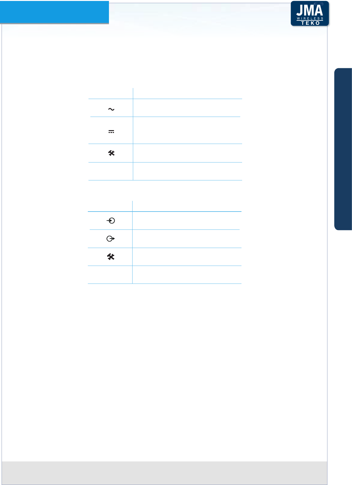
Teko DAS Platform Technical Handbook Doc ID Number 91 080 0783 rev. 01 | page A58
TEKO DAS Platform
Four LED indicators are available on the front panel of each Power Supply Module.
Front Panel LEDs description:
TRPSU/AC-58-1.2• K
Symbol Description
ON: input ok
Blinking: input out of limits
ON: output ok
Blinking: overload
OFF: no DC output
ON: over-temperature warning
Blinking: service
!
ON: fault
TRPSU/48-58-2• K
Symbol Description
ON: input ok
Blinking: input out of limits
ON: output ok
Blinking: overload
ON: over-temperature warning
Blinking: service
!
ON: fault
A
B
C
Components & Solutions

Teko DAS Platform Technical Handbook Doc ID Number 91 080 0783 rev. 01 | page A59
TEKO DAS Platform
SUB-RPSU2-MU/AC Ì and SUB-RPSU-MU/AC: power supply distribution system equipped
with AC/DC power supply modules
Rear Access Points
RS 485
Equipment
Grounding
AC MAINS socket
PS module 1
AC MAINS socket
PS module 2
AC MAINS socket
PS module 4
AC MAINS socket
PS module 3
SUB-RPSU2-MU/AC and SUB-RPSU-MU/AC - Rear view - Access pointsFigure A45 –
SUB-RPSU2-MU/48 Ì and SUB-RPSU-MU/48: power supply distribution system equipped
with DC/DC power supply modules
Rear Access Points
RS 485
Equipment
Grounding
VDC Input
to PS modules 3 and 4
VDC Input
to PS modules 1 and 2
SUB-RPSU2-MU/48 and SUB-RPSU-MU/48 - Rear view - Access pointsFigure A46 –
A
B
C
Components & Solutions
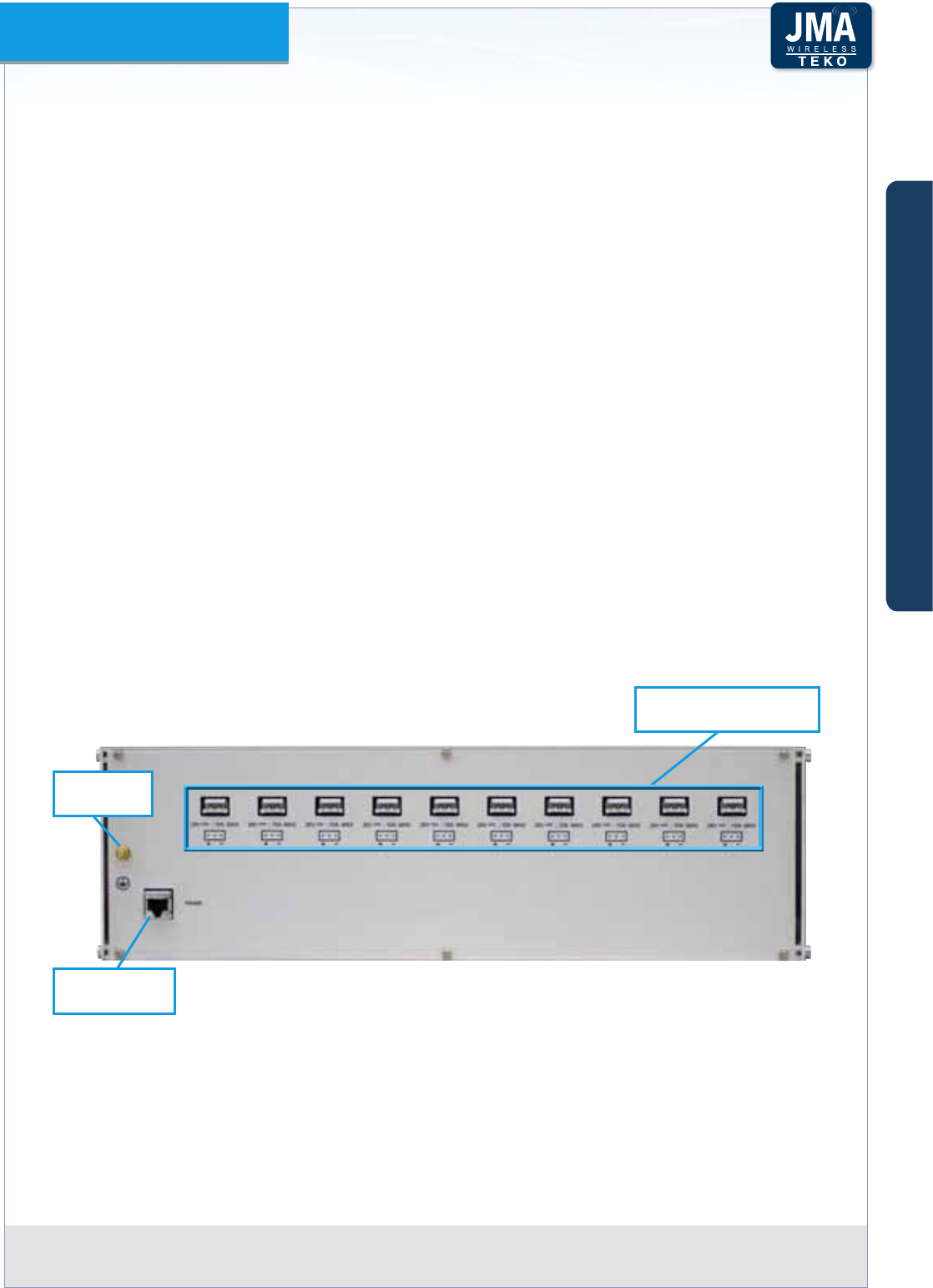
Teko DAS Platform Technical Handbook Doc ID Number 91 080 0783 rev. 01 | page A60
TEKO DAS Platform
Subracks hosting the System modulesA.2.8
Active subracks (SUB-TRX-PSU)•
Active Subracks are provided with a backplane that allows the management and power
supply of up to 12 active modules.
The following connectors are available on each active subrack rear panel:
a ground bolt; -
one or more 28Vdc input/output connectors; -
an RJ45 connector (RS485) to be used to connect monitored Active Subracks to the RS485 -
ports, available on the front panel of the Supervision Module (when power supply modules
are not equipped in monitored Active Subracks).
Please note
Master SUB-TRX-PSU: the RJ45 connector, available on the rear panel of the SUB-TRX-PSU
hosting the Supervision module, is used only when the System is equipped with the SUB-
PSU-MU in addition to other 12 monitored Active Subracks, connected to the Supervision
Module RS485 front ports. It provides an additional port for the management of the power
supply subrack.
Remote SUB-TRX-PSU: the RS485 port, available on the rear panel of a Remote Point to Point
Slave Subrack, is used only when a SUB-PSU-MU or SUB-PSU-MU/48 subrack is installed to
provide power supply to the remote subracks.
28VDC ± 0.5VDC outputs
(max 10A each)
Equipment
Grounding
RS 485
RJ45 connector
Active Subrack - rear viewFigure A47 –
A
B
C
Components & Solutions

Teko DAS Platform Technical Handbook Doc ID Number 91 080 0783 rev. 01 | page A61
TEKO DAS Platform
Deep subracks (SUB-TRX-PSU-D)
19” - 3U, 360mm (14.17in) deep subracks are required to host fully equipped Digital Donor
Front End modules.
Please note
Extender boards are required to plug standard-depth modules into deep subracks.
Teko Extender Board (TME-SUB-TRX-D)Figure A48 –
Passive subracks (SUB-HPOI)•
Passive modules that do not require power nor management to function can be housed in
Passive subracks thus allowing a reduction in the cost of the whole system.
A
B
C
Components & Solutions

Teko DAS Platform Technical Handbook Doc ID Number 91 080 0783 rev. 01 | page A62
TEKO DAS Platform
Forced-air cooling SubrackA.2.9
Teko forced-air cooling subrack is able to provide a maximum air ow of 180cfm (5m3/min) in
order to ensure the proper operation of cabinet installed equipment.
Forced-air cooling Subrack Access Points
LED
Forced-air cooling subrack - Front viewFigure A49 –
28V ;10A MAX RS485
GND
Forced-air cooling subrack - Figure A50 – Rear view
Access Point Description
LED Forced-air cooling subrack general operating status LED
Green: normal operation
Blinking Orange: presence of active alarms with warning severity level
Orange: presence of active alarms with minor severity level
Blinking Red: presence of active alarms with major severity level
Red: presence of active alarms with critical severity level
RS485 RJ45 connector for RS485 connection to the Supervision Module
28V ;10A MAX 28VDC ± 0.5VDC input (max 10A)
GND Equipment grounding
A
B
C
Components & Solutions
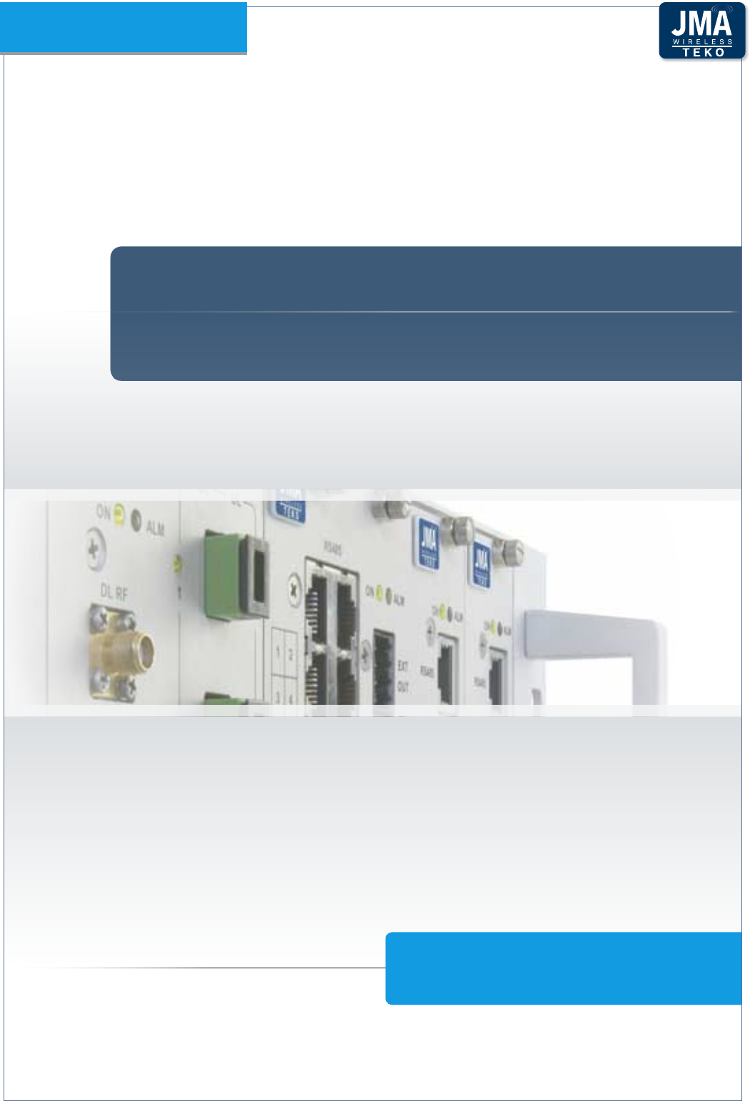
TEKO DAS PLATFORM
PART A - COMPOnEnTS AnD SOLuTiOnS
TEKO DAS Platform
COVERAGE SOLUTIONS
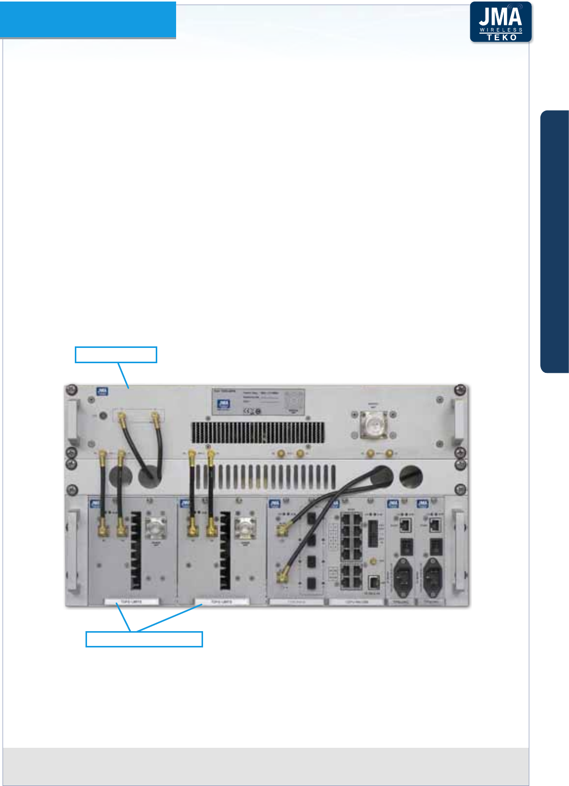
Teko DAS Platform Technical Handbook Doc ID Number 91 080 0783 rev. 01 | page A64
TEKO DAS Platform
Coverage and Capacity SolutionsA3
The components of the Teko Platform can be assembled to provide Modular Repeaters, Optical
DAS and integrated solutions to improve coverage in dierent environments.
Rack-mounted Modular RepeaterA.3.1
The Teko platform can be congured for RF repeater applications where the need for optimized
signal coverage is adequate to provide better end-user service that is transparent to protocol
and modulation.
Populating the Teko Master Unit with digital Donor Front End (DFE) and service front-end
modules, multi-band, multi-operator coverage solutions can be congured.
The modularity of the Teko platform allows easy adaptability to new technologies or extending
the solutions to additional operators as needed.
No physical connections are required between the Modular Repeaters and the cellular network:
the Digital Donor Front End is connected to a Donor Antenna, providing the connection
towards a BTS or NodeB/e-NodeB over an air link.
Donor Front End Modules
Service Front End
Rack-mounted Modular Repeater exampleFigure A51 –
The Digital Donor Front End is the single-band/single-operator RF interface towards the
signal source; the Service Front End is the multi-band/single operator equipment that
provides enhanced wireless signal to the area to be covered.
A
B
C
Components & Solutions
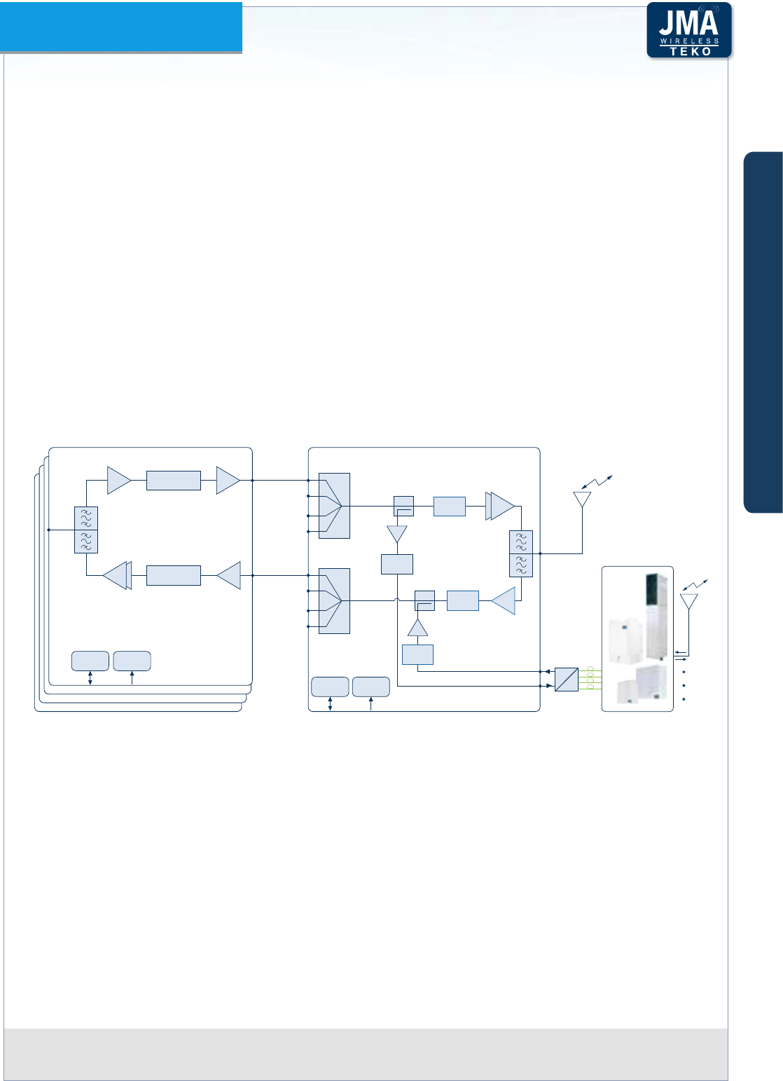
Teko DAS Platform Technical Handbook Doc ID Number 91 080 0783 rev. 01 | page A65
TEKO DAS Platform
Multiple DFEs (up to 4) can be connected with a single service front-end for single band,
multi-operator congurations. Multiple service front-ends can be utilized with multiple DFEs
to create multi-band, multi-operator solutions.
Operating principle
Modular repeaters use a directional antenna to interface with the operator’s donor BS and one
or more service antennas to transmit the amplied wireless signal to the area to be covered.
In downlink the repeater receives the signals from the BS, amplies them and re-transmits
them to the mobiles. In uplink the repeater receives the signals from the mobiles (MS),
amplies them and re- transmits them to the base station.
When Modular Repeaters do not provide satisfactory coverage (extensive areas, long tunnels),
they can be used along with a ber fed System (Teko Optical DAS).
TSFE
DL RF
Input 1
Service
Antenna
Port
Duplexer
DL RF Input 2
(from TDFE 2)
UL RF Output 2
(to TDFE 2)
DL RF Input 3
(from TDFE 3)
UL RF Output 3
(to TDFE 3)
DL RF Input 4
(from TDFE 4)
UL RF Output 4
(to TDFE 4)
4:1
4:1
Digital
Attenuator
Digital
Attenuator
RS485
TDFE 1
DL RF
Output
UL RF
Input UL RF
Output 1
Donor
Antenna
Port DUPLEXER
Digital Filter
Digital Filter
LNA
TDFE 2
TDFE 3
TDFE 4
DC/DC
μP
28÷30VDC
PA
Digital
Attenuator PA
LNA
Digital
Attenuator
Remote
Units
To/From
Remote
Units
Fiber Optic
TX/RX
Auxiliary DL Out
To Optics
Auxiliary UL In
From Optics
E
O
OPTICAL SYSTEM & DAS
DC/DC
μP
28÷30VDC
Rack-mounted Modular Repeaters block diagramFigure A52 –
A
B
C
Components & Solutions

Teko DAS Platform Technical Handbook Doc ID Number 91 080 0783 rev. 01 | page A66
TEKO DAS Platform
Optical DASA.3.2
The Teko Platform components can be congured to provide multi-carrier Optical Distributed
Antenna Systems.
Optical Systems are based on the Radio over Fiber technology, which enables radio signal
transmission over optical ber. This technology oers wide bandwidth and very little loss
along the ber optic cable, allowing the signals to be propagated over long distances. This
allows extensive areas coverage.
Each Teko Optical DAS is made up of two main parts: the Master Unit, interfacing the signal
source, and Remote Units, distributed throughout the territory to be served. Master Unit and
Remote Units are connected via single mode optical ber (SMR 9/125).
Master UnitA –
The Master Unit provides both the RF interface towards the signal source (one or more BTSs
or NodeBs/e-NodeBs) and the optical interface towards Remote Units.
It is a rack-based modular equipment: Teko Coverage and Capacity Systems components can
be assembled in a variety of ways providing dierent Master Unit conguration options.
Each Master Unit can be equipped with one or more RF interface subracks, hosting RF interface
modules and with one or more Optical Subracks, hosting Fiber Optic Transmitter/Receiver
modules.
When the Master Unit is equipped with Master and Slave Point to Point Modules, RF interface
subracks and optical subracks can be separated by a maximum distance of 20km.
RF interface subracks•
RF Interface subracks operate over dierent frequencies and with various frequency
combinations in the frequency range from 380 to 2700MHz.
Each RF interface subrack can be equipped with one or more RF Interface modules.
Master Unit RF Interface modules can be Point of Interface (POI/TAPOI/TDTPOI) modules and/
or Donor Front End modules.
Master Units equipped with POI/TAPOI/ TDTPOI modules must be installed next to the donor
BTS or NodeB/e-NodeB).
POI modules can be equipped in passive subracks; TAPOI/TDTPOI modules require active
subracks (SUB-TRX).
Donor Front End modules allow the Optical DAS to be driven without the need of a dedicated
BTS or NodeB/e-NodeB: each Donor Front End module interfaces with a Donor Antenna
oriented towards a BTS or NodeB/e-NodeB (connection over an air link).
Active Subracks are required to host Digital Donor Front Ends; fully equipped Digital Donor
Front Ends require deep Active Subracks (depth = 360mm / 14.17in). Each subrack can be
equipped with up to 4 Donor Front End Modules.
A
B
C
Components & Solutions

Teko DAS Platform Technical Handbook Doc ID Number 91 080 0783 rev. 01 | page A67
TEKO DAS Platform
RF Interface subracks also host passive modules providing distribution and ltering:
Splitter/Combiner•
Band Splitter/Combiner (Triplexer) with or without built-in 1:4 Splitter/Combiner•
Pentaplexer/Esaplexer.•
Due to the exible conguration options of Teko Coverage and Capacity Systems, the same
passive modules can be used for dierent purposes:
the splitter/combiner can be used to manage multiple RF interface modules, operating in •
the same band (Multi-Operator Optical Systems) or multiple Fiber Optic modules;
the triplexer (with built-in 4-way Splitter/Combiner) can be used to manage•
up to 3 RF interface modules operating in dierent bands (and up to 4 Fiber Optic -
Transmitter/Receiver Modules) or
up to 3 Service Front End subracks operating in dierent bands (and up to 4 Fiber Optic -
Transmitter/Receiver Modules) or
up to 3 four-way splitter/combiner modules, used to manage multiple RF interface -
modules -up to 4 for each band (and up to 4 Fiber Optic Transmitter/Receiver Modules).
the Pentaplexer and Esaplexer can be used to manage•
up to 5 (Pentaplexer)/ up to 6 (Esaplexer) RF interface modules operating in dierent -
bands or
up to 5 (Pentaplexer)/ up to 6 (Esaplexer) Service Front End subracks operating in -
dierent bands or
up to 5 (Pentaplexer)/ up to 6 (Esaplexer) four-way splitter/combiner modules- used to -
manage multiple RF interface modules (up to 4 for each band).
The RF Interface subracks can also host up to 4 Master Point to Point modules for the
management of up to 4 optical subracks installed in dierent remote locations.
Digital Donor Front End modules can be connected to Service Front End Subracks to provide
coverage to the area adjoining the Master Unit site.
Each Service Front End can be fed by up to 4 Donor Front-End Modules interfacing the signal
source. Downlink and uplink auxiliary ports are available to drive the Optical System.
A
B
C
Components & Solutions
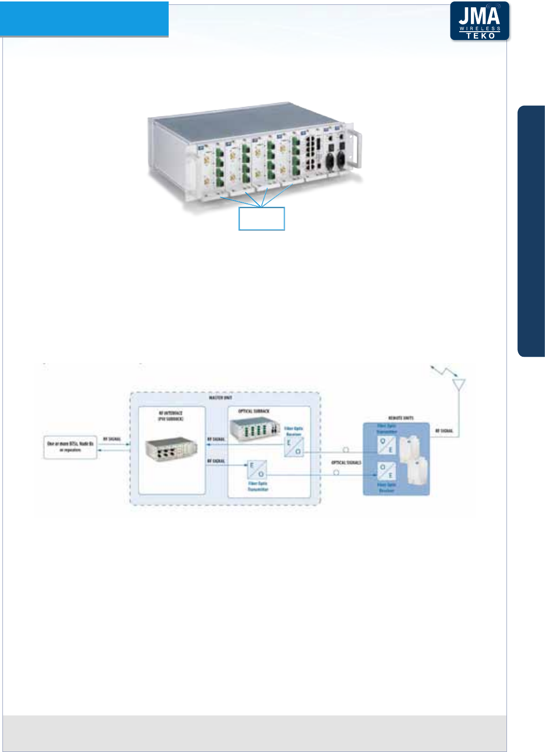
Teko DAS Platform Technical Handbook Doc ID Number 91 080 0783 rev. 01 | page A68
TEKO DAS Platform
Optical Subracks•
Optical Subracks are Active Subracks hosting Fiber Optic Transmitter/Receiver modules.
Fiber Optic
Modules
Optical Subrack (example)Figure A53 –
Fiber Optic Transmitter/Receiver modules are the optical interface towards Remote Units:
they provide RF to optical /optical to RF conversion.
Fiber Optic modules are connected to Remote Units via single-mode optical ber (SMR
9/125); each Fiber Optic Module can manage up to 4 Remote Units (up to 5 in cascade
conguration).
Up to 6 Fiber Optic Modules can be housed in a single Optical Subrack.
In Downlink RF signals are converted into optical signals in the Fiber Optic Transmitter modules
of the Master Unit and then they are propagated through optical ber distribution to Remote
Units. In the Fiber Optic Receiver of each Remote Unit, the optical signal is then converted
back into an RF signal that is amplied and transmitted to mobiles through an antenna or a
passive distribution system.
In Uplink RF signal is converted into an optical signal in the Fiber Optic Transmitter of each
Remote Unit and then it is propagated via ber optics to the Master Unit. Optical signals from
Remote Units are then converted by the Fiber Optic Receiver modules of the Master Unit into
RF signals and transmitted to the signal recipient.
Uplink and downlink optical signals are transmitted over the same single mode optical ber
A
B
C
Components & Solutions

Teko DAS Platform Technical Handbook Doc ID Number 91 080 0783 rev. 01 | page A69
TEKO DAS Platform
(Wavelength Division Multiplexing -WDM- technology).
When the Coverage System includes point to point links, the remote optical subracks host the
Slave point to point modules to be connected, via optical ber, to their Master Point to Point
modules, equipped in the RF interface subracks.
The slave point to point module includes the 4-way splitter/combiner to manage up to 4
Fiber Optic Transmitter/Receiver Modules and a built-in Supervision unit for the management
of the remote optical subrack, the power supply subrack (SUB-PSU-MU or SUB-PSU-MU/48,
when equipped), and all connected Remote Units.
When Remote optical subracks are equipped with 2 or 3 Slave Point to Point Modules only
one module is connected to the System Supervision module (the one installed on the left side
of the remote subrack - slots 1 to 6).
4-WAY
SPLITTER
COMBINER
TRIPLEXER
+
4-WAY
SPLITTER
COMBINER
FIBER OPTIC
TRANSMITTER
RECEIVER
MODULES
4-WAY
SPLITTER
COMBINER
4-WAY
SPLITTER
COMBINER
TO/FROM
REMOTE UNITS
SIGNAL SOURCE
SIGNAL SOURCE
SIGNAL SOURCE
INTERFACE MODULES
OPERATING IN THE
SAME BAND
INTERFACE MODULE:
POI MODULE or
TDFE MODULE
INTERFACE MODULES
OPERATING IN THE
SAME BAND
INTERFACE MODULE:
POI MODULE or
TDFE MODULE
INTERFACE MODULES
OPERATING IN THE
SAME BAND
INTERFACE MODULE:
POI MODULE or
TDFE MODULE
MASTER
POINT TO POINT
MODULE
SLAVE
POINT TO POINT
MODULE
POINT TO
POINT
OPTICAL LINK
POINT TO
POINT
OPTICAL LINK
MASTER
POINT TO POINT
MODULE
REMOTE OPTICAL
SUBRACK 1
FIBER OPTIC
TRANSMITTER
RECEIVER
MODULES
TO/FROM
REMOTE UNITS
FIBER OPTIC
TRANSMITTER
RECEIVER
MODULES
TO/FROM
REMOTE UNITS
SLAVE
POINT TO POINT
MODULE
REMOTE OPTICAL
SUBRACK 2
OPTICAL SUBRACK
MULTI-OPERATOR MULTI-STANDARD RF INTERFACE
EQUIPPED WITH MASTER POINT TO POINT MODULES
Example: Optical DAS serving 2 remote optical subracksFigure A54 –
A
B
C
Components & Solutions
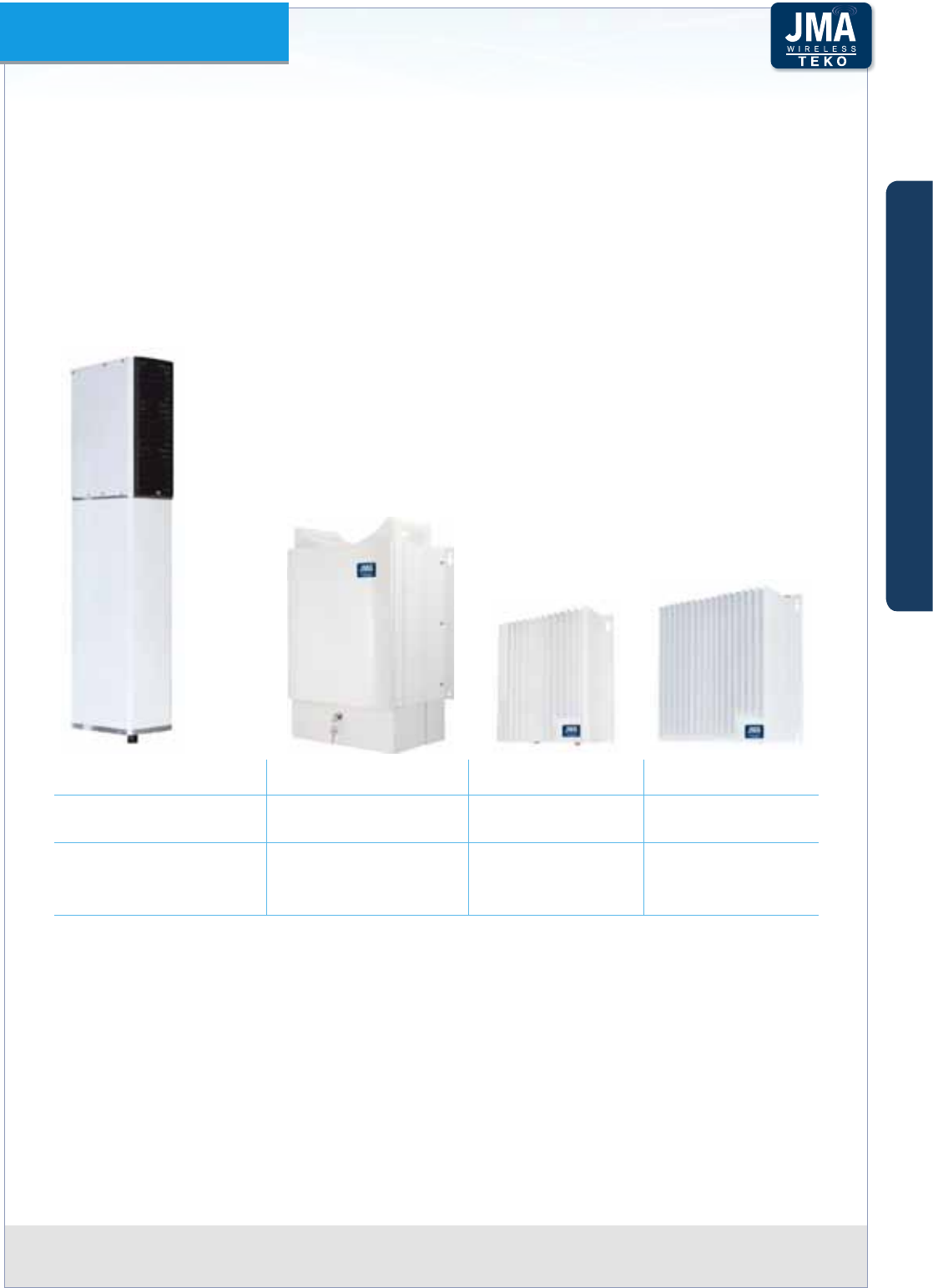
Teko DAS Platform Technical Handbook Doc ID Number 91 080 0783 rev. 01 | page A70
TEKO DAS Platform
B – Remote Units
Remote Units distribute wireless signals throughout the area to be covered; they can be
installed up to 20km (12.4miles) from the Master Unit site.
Remote Units can be Single band or Multi-band with dierent power classes.
Pole-mounting Remote Unit mechanical design allows the Unit to be mounted inside utility
poles with 12” internal radius. The Unit can also be mounted outside, fastened to a thinner
pole, due to its IP66 rating.
Pole-mount Remote Unit Boxed Remote Unit Low Power Remote Unit Low Power Remote Unit
Multi-band Single, Dual, Tri-band Single, Dual, Tri-band 4-band,5-band,6-band
Mechanical design
optimized for Pole
Mounting (inside/outside)
Wall Mounting
(pole mounting kit
available as option)
Wall Mounting (pole
mounting kit available
as option)
Wall Mounting (pole
mounting kit available
as option)
Remote Units are equipped with the Fiber Optic Receiver and Transmitter modules (for Optical
to RF and RF to Optical conversion) power ampliers and ltering.
A single Master Unit can drive up to 144 Remote Units. Various network structures can be
supported by the Master Unit: the Remote Units of the same Optical System can be deployed
with a point-to-point connection (star-conguration - using one ber optic per Remote Unit) or
with cascading of up to 5 Remote Units using a single ber and optimized optical couplers.
A
B
C
Components & Solutions
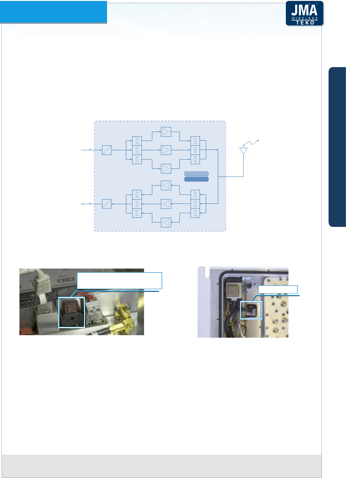
Teko DAS Platform Technical Handbook Doc ID Number 91 080 0783 rev. 01 | page A71
TEKO DAS Platform
The following gure shows the Tri-band wideband Remote Unit block diagram: in down-link
the optical signal from Master Unit is converted into an RF signal by the Fiber Optic Receiver
module. RF signals, ltered by the triplexer, are amplied by Power ampliers, ltered and
transmitted through an antenna or a passive distribution system.
In up-link the RF signal is ltered by the triplexer. The three RF signals are amplied by
Low-Noise Ampliers, ltered and then converted into an optical signal by the Fiber Optic
Transmitter module. The signal is transmitted via ber optics to the Master Unit.
Fiber Optic
Receiver
From MASTER unit
(DownLink)
To MASTER unit
(UpLink)
PA900
PA1800
PA2100
Antenna
System
LNA900
LNA1800
LNA2100
Fiber Optic
Transmitter
Management module
PSU
O
E
O
E
Example: Tri-band wideband RemoteFigure A55 – Unit block diagram
Please Note: each nal power amplier is protected by a fuse.
Final ampliers fuse position and electrical rating
Fuse 32V-7,5A HPA/MPA
Fuse 32V-20A VHPA/WHPA (40W) Fuse 32V-7,5A
Low Power Remote Unit nal amplier fuse
position and electrical rating
The management module collects information relevant to the various modules. An RF modem
allows data communication over ber between Remote Unit and Master Unit.
A
B
C
Components & Solutions
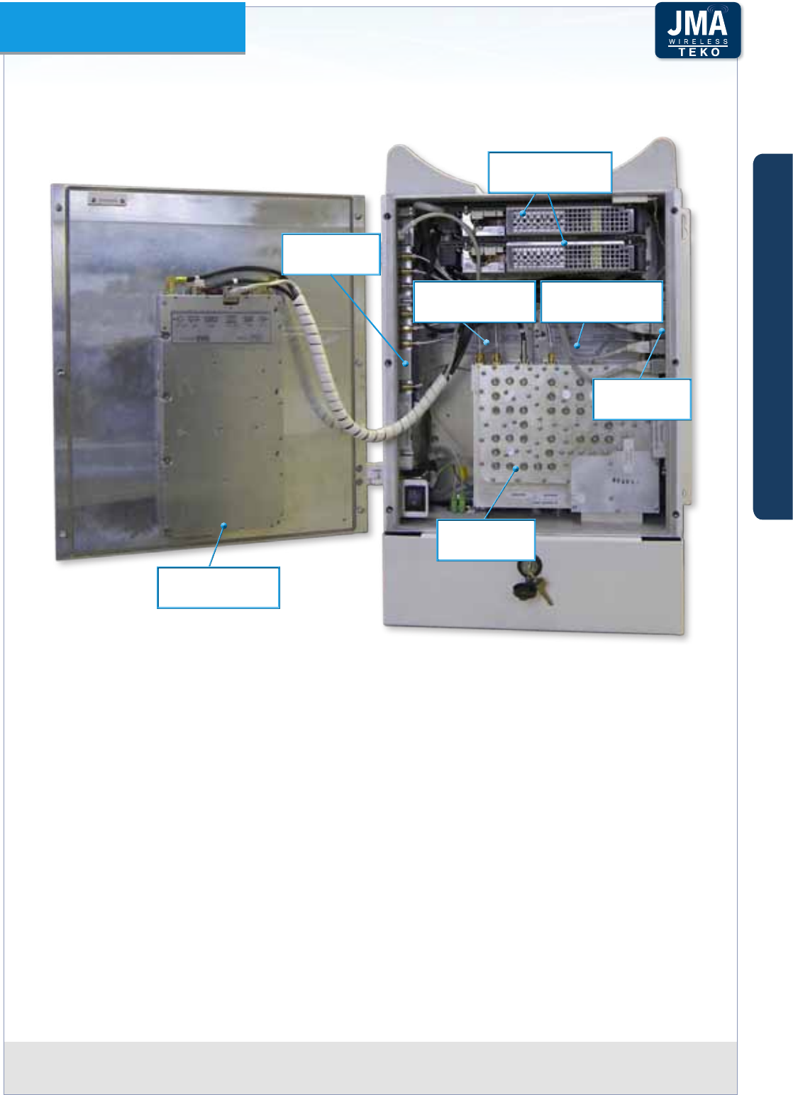
Teko DAS Platform Technical Handbook Doc ID Number 91 080 0783 rev. 01 | page A72
TEKO DAS Platform
High/Medium Power boxed Remote Units Composition•
POWER SUPPLY
MODULES
SUPERVISION
MODULE
FIBER OPTIC
MODULE
POWER AMPLIFIER
(BAND1)
POWER AMPLIFIER
(BAND2)
POWER AMPLIFIER
(BAND3)
CAVITY
6-PLEXER
A
B
C
Components & Solutions
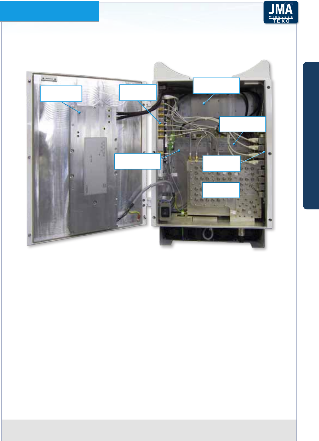
Teko DAS Platform Technical Handbook Doc ID Number 91 080 0783 rev. 01 | page A73
TEKO DAS Platform
Very High Power boxed Remote Unit Composition
POWER SUPPLY
MODULE
CAVITY
6-PLEXER
SUPERVISION
MODULE
FIBER OPTIC
MODULE
POWER AMPLIFIER
(BAND1)
POWER AMPLIFIER
(BAND2)
POWER AMPLIFIER
(BAND3)
PLEASE NOTE
The boxed Remote Unit case is equipped with a lock to guarantee protection of the equipment.
The following procedure describes how to open the equipment.
OPENING THE REMOTE UNIT
Unlock the cables protection using the keys delivered with the equipment•
Remove the cables protection•
Remove the Remote Unit cover, sliding it downwards•
Unscrew the 6 screws on the Remote Unit door•
Open the Remote Unit door.•
A
B
C
Components & Solutions

Teko DAS Platform Technical Handbook Doc ID Number 91 080 0783 rev. 01 | page A74
TEKO DAS Platform
Remote Units can be either AC powered or DC powered.
The following gures show power supply modules protection fuses position and electrical rating.
Fuse SMD F10A, 125V
Low Power Remote Unit: DC/DC Power Supply Module protection fuse position and electrical Figure A56 –
rating
F20A, 250V
F20A, 250V
Boxed Very High Power and pole-mount Remote Units: DC/DC Power Supply Module protection Figure A57 –
fuses position and electrical rating
F20A, 250V
F25A, 250V
Boxed Very High Power and pole-mount Remote Units: AC/DC Power Supply Module protection Figure A58 –
fuses position and electrical rating
A
B
C
Components & Solutions
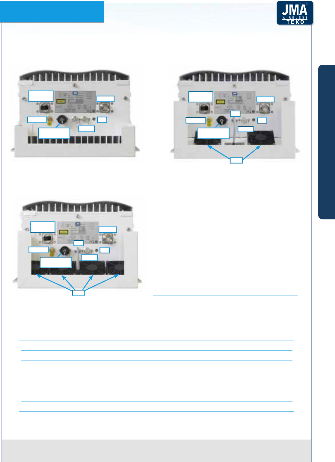
Teko DAS Platform Technical Handbook Doc ID Number 91 080 0783 rev. 01 | page A75
TEKO DAS Platform
Remote Units External Access Points•
Boxed Remote Units External Access Points
GROUND
OPTICAL
DL/UL WDM
ALARM
RF PORT
LED
Medium power and Single band High power Remote Units
Connector side view
GROUND
OPTICAL
DL/UL WDM
ALARM
RF PORT
LED
FAN
FANS
Dual band/Triband high power Remote Units
Connector side view
Very high power Remote Units and high power Remote Units
equipped with ampliers operating in the LTE2600 band
Connector side view
GROUND
OPTICAL
DL/UL WDM
ALARM
RF PORT
LED
FAN
FANS
REMOTE UNIT GENERAL OPERATING STATUS
LED DESCRIPTION LED
Green: regular operation (no alarm)
Blinking Orange: presence of active alarms with
warning severity level
Orange: presence of active alarms with minor
severity level
Blinking Red: presence of active alarms with
major severity level
Red: presence of active alarms with critical
severity level
POWER SUPPLY
INPUT
POWER SUPPLY
INPUT
POWER SUPPLY
INPUT
Label (Connectors) Description
RF PORT RF connector - 7/16 (f) type duplex
OPTICAL DL/UL WDM Optical ber input/output connector (laser aperture)
GROUND Equipment grounding
POWER SUPPLY
INPUT
AC voltage input (100-240Vac)
DC voltage input (-72 ÷ -36Vdc)
FAN Fans power supply and control connector
ALARM Auxiliary alarms connector (4 in, 4 out)
A
B
C
Components & Solutions
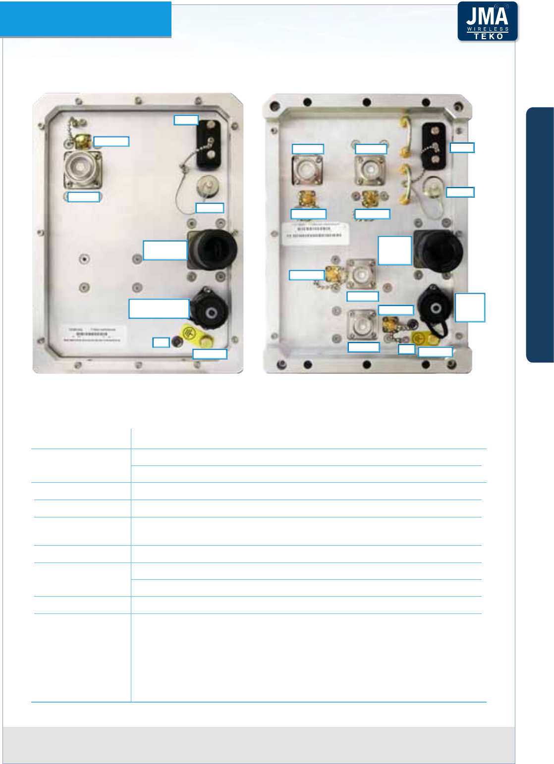
Teko DAS Platform Technical Handbook Doc ID Number 91 080 0783 rev. 01 | page A76
TEKO DAS Platform
Pole-mount Remote Units External Access Points
Pole mount single band/multi-band
High Power/ Very High power wideband
Remote Units - Connector side view
GROUND
OPTICAL
DL/UL WDM
ALARM
RS232
RF PORT
POWER SUPPLY
INPUT
LED
COUPLER
Pole mount multi-band 40W output power
Duplexed Remote Units
Connector side view
GROUND
OPTICAL
DL/UL
WDM
ALARM
RS232
RF PORT RF PORT
RF PORT
RF PORT
POWER
SUPPLY
INPUT
LED
COUPLER COUPLER
COUPLER
COUPLER
Label (Connectors) Description
RF PORT Wideband Remote Units: 1 x RF connector - 7/16 (f) type duplex
40W duplexed Remote Units 4 x RF connectors - 4.3-10 (f) type
COUPLER Monitor port(s) for measurements (Mobile Station side)
RS 232 Factory use only
OPTICAL DL/UL
WDM
Optical ber input/output connector (laser aperture)
GROUND Equipment grounding
POWER SUPPLY
INPUT
AC voltage input: 100-240Vac
DC voltage input: -72 ÷ -36Vdc
ALARM Auxiliary alarms connector (4 in, 4 out)
LED Remote Unit General Operating STATUS LED description
Green: regular operation (no alarm)
Blinking Orange: presence of active alarms with warning severity level
Orange: presence of active alarms with minor severity level
Blinking Red: presence of active alarms with major severity level
Red: presence of active alarms with critical severity level
A
B
C
Components & Solutions
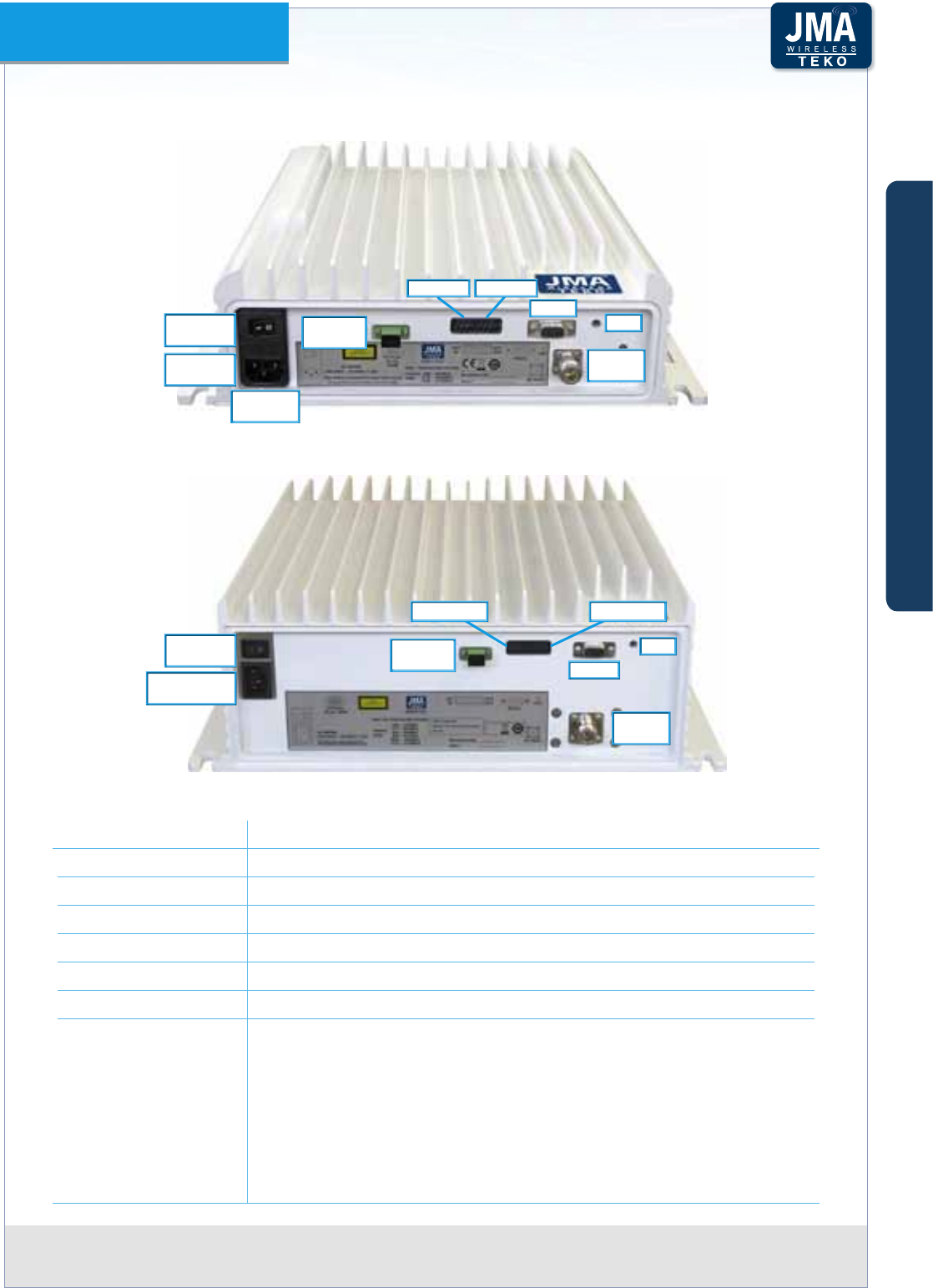
Teko DAS Platform Technical Handbook Doc ID Number 91 080 0783 rev. 01 | page A77
TEKO DAS Platform
Low Power Remote Units External Access Points (AC Powered)
AC
MAINS
MAINS
SOCKET
MAINS
SWITCH
RS232
RF
PORT
LED
OPTICAL
DL/UL
EXT IN EXT OUT
Single/Dual/Tri-Band Low Power Remote Units External Access Points
Vac MAINS
CONNECTOR
AC MAINS
SWITCH RS232
RF
PORT
LED
OPTICAL
DL/UL
EXT OUTEXT IN
Six-Band Low Power Remote Unit External Access Points
Label (Connectors) Description
RF PORT RF connector - N (f) or 4.3-10 (f ) type duplex
OPTICAL DL/UL Optical ber input/output SC-APC connector (laser aperture)
AC MAINS AC voltage input (100-240Vac) and switch
EXT OUT External alarms output connector
EXT IN External alarms input connector
RS 232 Factory use only
LED Remote Unit general operating status LED
Green: no alarm
Blinking Orange: presence of active alarms with warning severity
level
Orange: presence of active alarms with minor severity level
Blinking Red: presence of active alarms with major severity level
Red: presence of active alarms with critical severity level
A
B
C
Components & Solutions
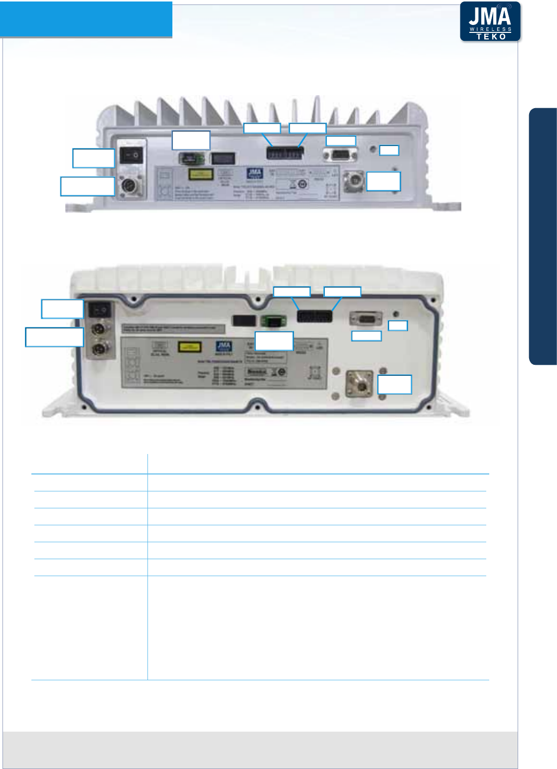
Teko DAS Platform Technical Handbook Doc ID Number 91 080 0783 rev. 01 | page A78
TEKO DAS Platform
DC Powered Low Power Remote Unit External Access Points
Vdc INPUT
CONNECTOR
48Vdc
SWITCH
EXT IN EXT OUT
RS232
RF
PORT
LED
OPTICAL
DL/UL
Vdc INPUT
CONNECTORS
48Vdc
SWITCH
RS232
RF
PORT
LED
OPTICAL
DL/UL
EXT OUTEXT IN
Label (Connectors) Description
RF PORT RF connector - N (f) or 4.3-10 (f ) type duplex
OPTICAL DL/UL Optical ber input/output SC-APC connector (laser aperture)
48V Vdc input connector (48Vdc) and switch
EXT OUT External alarms output connector
EXT IN External alarms input connector
RS 232 Factory use only
LED Remote Unit general operating status LED
Green: no alarm
Blinking Orange: presence of active alarms with warning severity
level
Orange: presence of active alarms with minor severity level
Blinking Red: presence of active alarms with major severity level
Red: presence of active alarms with critical severity level
A
B
C
Components & Solutions

Teko DAS Platform Technical Handbook Doc ID Number 91 080 0783 rev. 01 | page A79
TEKO DAS Platform
Coverage Systems Management and Power SupplyA.3.3
Coverage Systems can be accessed and managed simply connecting a PC, either locally or
remotely, to the IP address of the System Supervision Module.
The Supervision Module Communication Interfaces (Ethernet LAN port / Modem) allow the
System to be managed either by a Local Maintenance Terminal (LMT), connected locally to
the Supervision Module LAN port, or by a Network Element Manager (NEM). The connection
with a Network Element Manager (NEM) can be either a physical (Ethernet LAN) or a modem
connection.
The optional wireless modem (GSM/GPRS or GSM/GPRS/UMTS), integrated inside the
Supervision module, allows the Coverage System remote management. A VPN application
installed on the Supervision Module provides remote and secure access to the System using
the Internet. An embedded SNMP agent software is available to provide a Northbound SNMP
interface, allowing easy integration into upper level Network Management Systems (NMS).
The management of the System is performed via JMA Wireless Teko OMT (Operation and
Maintenance Terminal) web pages: the Supervision Module is equipped with a web-server and
each component of the System is associated to a web page displaying detailed information
about the component.
OMT web pages show the Coverage System operating parameters and alarm status. They
allow the commissioning, monitoring, setting and troubleshooting of the whole Coverage
System. Please refer to JMA Wireless Teko OMT web pages User’s Guide for details.
Teko Operation Management Centre (OMC) proprietary software allows the management
of multiple Teko Coverage and Capacity Systems in a Network. Please refer to Teko OMC
User’s Guide for details.
A single Teko Supervision (TSPV) allows the management of an entire Coverage and Capacity
System:
Rack-mount Light Supervision shelf Ì
A rack mount Light Supervision shelf is available for modular repeaters or small/medium
DAS: it is able to manage up to 4 Active Subracks. Four ports (RS485) are available on
the Supervision front panel to be connected to the RS485 ports of monitored Active
Subracks.
Rack-mount Light Supervision shelfFigure A59 –
A
B
C
Components & Solutions
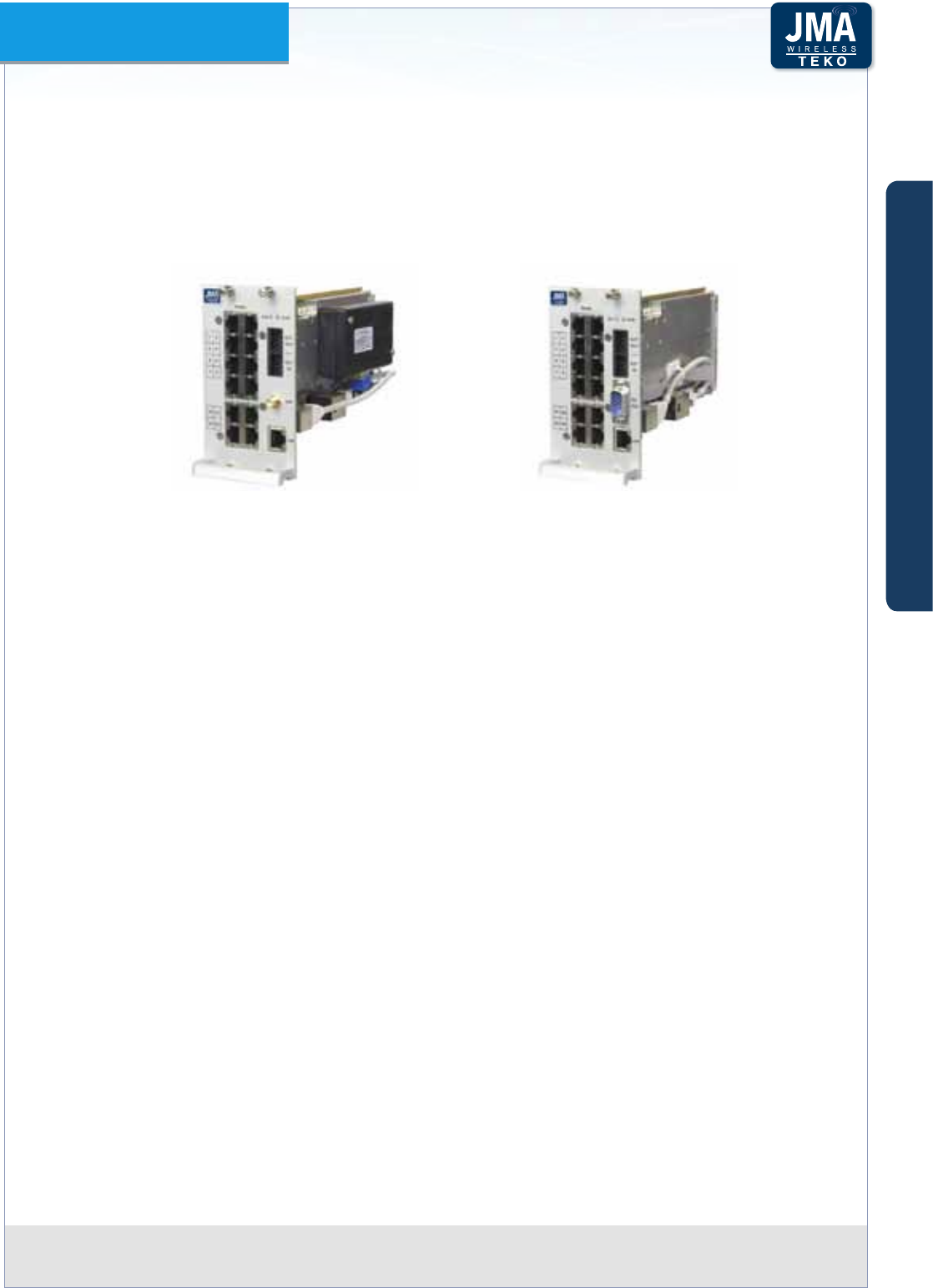
Teko DAS Platform Technical Handbook Doc ID Number 91 080 0783 rev. 01 | page A80
TEKO DAS Platform
Supervision Module Ì
A Supervision module is available for the management of more sophisticated Teko DAS
architectures: the module is able to manage the Active Subrack it is equipped in (Master
Subrack), the power supply subrack, up to other 12 Active Subracks (Monitored Subracks),
and all connected Remote Units.
Supervision Module with optional wireless modem (left) without wireless modem (right)Figure A60 –
Twelve ports (1 to 8 and S1 to S4) are available on the Supervision Module front panel to
be connected to the RS485 ports of monitored Active Subracks.
Ports numbered from 1 to 8•
The ports numbered from 1 to 8 are available for the connection to monitored subracks
mounted within the same rack hosting the Master Subrack.
Ports numbered from S1 to S4•
The other four ports (S1 to S4) are available for the management of remote active
subracks equipped with Point to Point Slave modules.
The Slave Point to Point module installed on the left side of the remote slave subrack
(slots 1 to 6) manages the remote optical subrack, the remote power supply subrack
(if any), and all connected Remote Units. The Coverage System Supervision Module
communicates with the Slave Point to Point built-in Supervision via the single-mode
optical ber (SMR 9/125), connecting Master and Slave Point to Point modules.
The ports S1 to S4 not connected to remote subracks can be used to manage additional
subracks, mounted within the same rack hosting the Master Subrack.
Additional RS485 port available on the Master Subrack rear panel•
The RS485 connector, available on the rear panel of the SUB-TRX-PSU hosting the
Supervision module, provides an additional port for the management of the power
supply subrack (SUB-PSU-MU or SUB-PSU-MU/48). This port is used only when the
System is equipped with the power supply subrack in addition to other 12 monitored
Active Subracks, connected to the Supervision Module RS485 front ports.
RS485 port available on the Remote Subrack rear panel•
A
B
C
Components & Solutions

Teko DAS Platform Technical Handbook Doc ID Number 91 080 0783 rev. 01 | page A81
TEKO DAS Platform
The RS485 port, available on the rear panel of a Remote Point to Point Slave Subrack, is
used only when a SUB-PSU-MU or SUB-PSU-MU/48 is installed to provide power supply
to the remote subracks.
Address assignment
Each monitored Subrack takes its address from the Supervision Module port it is
connected to (please refer to Paragraph B.4.2 RS485 Connections for details).
The Active Subrack equipped with the Supervision Module (Master Subrack) takes address
= 0 (zero).
A
B
C
Components & Solutions
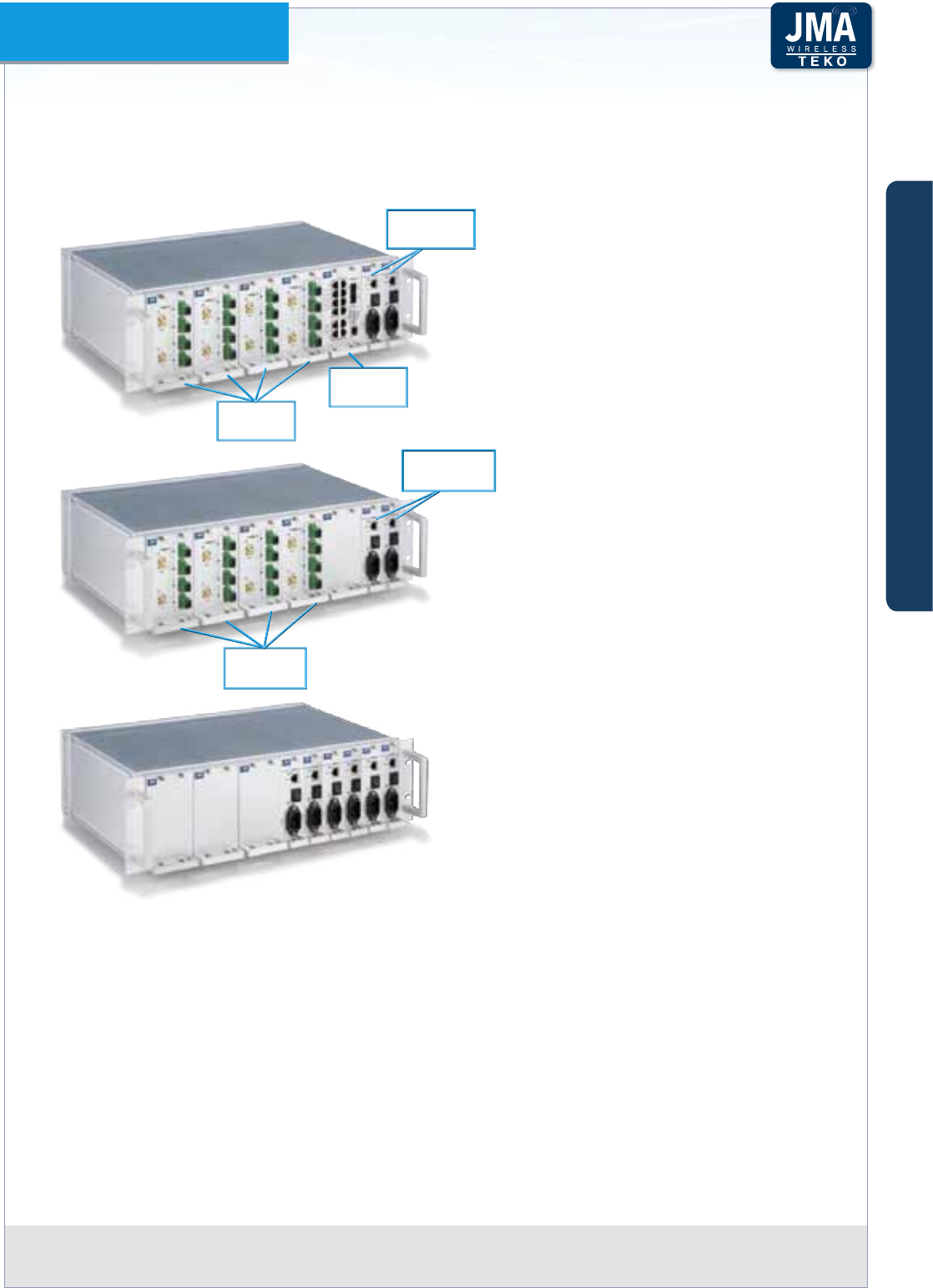
Teko DAS Platform Technical Handbook Doc ID Number 91 080 0783 rev. 01 | page A82
TEKO DAS Platform
Power Supply
Coverage Systems can be AC or DC powered. Power supply modules can be equipped in
monitored Active Subracks or in the Master Subrack or in dedicated Active Subracks.
Example of Power Supply Modules equipped
in the Master Optical Subrack (the second
Power Supply Module, optional, provides
power supply redundancy for higher
reliability).
Power Supply
Modules
Fiber Optic
Modules
Supervision
Module
Power Supply
Modules
Fiber Optic
Modules
Example of Power Supply Modules equipped
in a monitored Active Subrack. The RJ45
connector available on the Power Supply
Module front panel can be used for connection
to the Supervision Module, equipped in the
Master Active Subrack.
Example of Power Supply Modules equipped
in a dedicated Active Subrack.
Space ecient AC-to-DC and DC-to-DC Power Supply subracks are available to provide up to
2.4kW (AC/DC) / 3kW (DC/DC) maximum output power in just one height unit space.
A Power Supply distribution system is also available for the remote powering of Teko 48VDC
Low Power Remote Units.
Please refer to Paragraph A.2.7 for details.
A
B
C
Components & Solutions
Teko DAS Platform Technical Handbook Doc ID Number 91 080 0783 rev. 01 | page A83
TEKO DAS Platform
A.3.4 Coverage Systems Technical Specications
Coverage and Capacity Systems mechanical, environmental and power supply specications
are available in the following tables. Please refer to Teko datasheets for detailed specications.
Contact Teko Sales Oce for further information.
Remote Units•
Remote Unit model Dimensions (HxWxD)
max volume
Weight Operating
temperature range
IP rating Power
supply
LOW POWER
Single
Dual
Tri
band
N (f)
connector
≈ 355.5 x350x102mm
(14.00 x13.78x4.02 in) (*) 13kg
(28.7lbs)
-20°C up to +55°C
(-4°F up to +131°F)
IP32 (box)
IP66 (with
optional
protection
kit)
AC version:
85÷264Vac
(50-60Hz)
Nominal
range:
100÷240Vac
DC version:
-72 ÷ -36Vdc
4.3-10 (f)
connector
≈ 363 x350x102mm
(14.29 x13.78x4.02 in) (*)
5-US band
6-US band
N (f)
connector
≈ 414 x 414 x 145.6mm
(16.30 x 16.30 x 5.73in) (*) 19kg
(41.9lbs)
4.3-10 (f)
connector
≈ 421.4 x 414 x 145.6mm
(16.60 x 16.30 x 5.73in) (*)
4-US band
4-EU band
5-EU band
N (f)
connector
≈ 398.2x 414 x 145.6mm
(15.70 x 16.30 x 5.73in) (*) 19kg
(41.9lbs)
4.3-10 (f)
connector
≈ 405.6 x 414 x 145.6mm
(15.97 x 16.30 x 5.73in) (*)
(*) heat sinks and connectors included
BOXED MEDIUM POWER
Single band ≈ 570 x 408.5 x 263 mm
(22.44 x 16.08 x 10.35 in)
heat sinks, handles and
connectors included
26kg
(57.32 lbs)
-20°C up to +55°C
(-4°F up to +131°F)
IP66 AC version:
85÷264Vac
(50-60Hz)
Nominal
range:
100÷240Vac
DC version:
-72 ÷ -36Vdc
Dual band 28kg
(61.73lbs)
Triband 30kg
(66.1lbs)
BOXED HIGH POWER
Single band ≈ 570 x 408.5 x 263 mm
(22.44 x 16.08 x 10.35 in)
heat sinks, handles and
connectors included
28kg
(61.73lbs)
-20°C up to +55°C
(-4°F up to +131°F)
IP66 AC version:
85÷264Vac
(50-60Hz)
Nominal
range:
100÷240Vac
DC version:
-72 ÷ -36Vdc
Dual band 31kg
(68.34lbs)
Triband 32kg
(70.55lbs)
BOXED VERY HIGH POWER
Single band ≈ 620 x 408.5 x 263 mm
(24.41 x 16.08 x 10.35 in)
heat sinks, handles and
connectors included
36kg
(79.37lbs)
-20°C up to +55°C
(-4°F up to +131°F)
IP66 AC version:
85÷264Vac
(50-60Hz)
Nominal
range:
100÷240Vac
DC version:
-72 ÷ -36Vdc
Dual band 37kg
(81.57lbs)
Triband 38kg
(83.78lbs)
A
B
C
Components & Solutions

Teko DAS Platform Technical Handbook Doc ID Number 91 080 0783 rev. 01 | page A84
TEKO DAS Platform
Pole-mount Remote Units•
Remote Unit
model
Dimensions
(HxWxD)
Weight Operating
temperature range
IP rating Power
supply
Up to 4-EU band
Up to 5-US band
≈ 1060 x 185 x 273mm
(41.73 x 7.28 x 10.75in)
≈ 40kg
(88.18lbs)
-20°C up to +55°C
(-4°F up to +131°F)
IP66 AC version:
90÷264Vac
(50-60Hz)
Nominal
range:
100÷240Vac
DC version:
-72 ÷ -36Vdc
System Subracks•
Subrack Commercial Code and Description Dimensions Operating Temperature Range
SUB-TRX-PSU
Standard Active Subrack
19” - 3U
depth 270mm (10.63in)
-5°C up to +55°C (+23°F up to +131°F)
with proper forced-air cooling
SUB-HPOI
Standard Passive Subrack
19” - 3U
depth 270mm (10.63in)
-5°C up to +55°C
(+23°F to +131°F)
SUB-TRX-PSU-D
Deep Active Subrack, required to host fully
equipped Digital Donor Front End modules
19” - 3U
depth 360mm (14.17in)
-5°C up to +55°C
(+23°F to +131°F)
TSFE
Service Front End Subrack
19” - 2U
depth 360mm (14.17 in)
-5°C up to +55°C
(+23°F to +131°F)
TFAN191U4F28V
Forced-Air Cooling Subrack
19” - 1U
depth 270mm (10.63in)
-5°C up to +55°C
(+23°F to +131°F)
Power Supply Components•
Commercial Code and
Description
Dimensions Operating Temperature
Range
Output Power
TPSU/AC
AC/DC Power Supply
Module
3U - 7TE -5°C up to +55°C (+23°F
to +131°F) with proper
forced-air cooling
100W each, up to 2 in parallel
90W each, 3-4 in parallel
80W each, more than 4 in
parallel
TPSU/48
DC/DC Power Supply
Module
SUB-PSU-MU
AC/DC Power Supply
Subrack
(equipped with 1 to 3
TPSU/AC-30-1K, AC/DC
Power Supply module)
19” - 1U, depth
(handles included)
376mm (14.8in)
0°C up to +70°C (+32°F
to +158°F)
50 to 60°C, derate 2% /°C;
60 to 70°C, derate 2.5% /°C
900W, each AC/DC Power
Supply module
2430W, max conguration (3x
TPSU/AC-30-1K)
SUB-PSU-MU/48
DC/DC Power Supply
Subrack
(equipped with 1 to 3
TPSU/48-30-1K, DC/DC
Power Supply module)
19” - 1U, depth
(handles included)
376mm (14.8in)
-5°C up to +55°C (+23°F
to +131°F)
1kW
each DC/DC Power Supply
module
A
B
C
Components & Solutions

Teko DAS Platform Technical Handbook Doc ID Number 91 080 0783 rev. 01 | page A85
TEKO DAS Platform
Commercial Code and
Description
Dimensions Operating Temperature
Range
Output Power
SUB-RPSU2-MU/AC
SUB-RPSU-MU/AC
Power Supply
distribution system for
remote units
(equipped with 1 to 4
TRPSU/AC-58-1.2K
AC/DC Power Supply
module )
19” - 2U, depth
421.5mm (16.59in)
(handles and
connectors included)
-5°C up to +55°C (+23°F
to +131°F) with proper
forced-air cooling
1.2kW @110-120Vac
1.9kW @200-270Vac
each AC/DC Power Supply
module
SUB-RPSU2-MU/48 and
SUB-RPSU-MU/48
Power Supply
distribution system for
remote units
(equipped with 1 to 4
TRPSU/48-58-2K
DC/DC Power Supply
Module)
19” - 2U, depth
421.5mm (16.59in)
(handles and
connectors included)
-5°C up to +55°C (+23°F
to +131°F) with proper
forced-air cooling
1.9kW
each DC/DC Power Supply
module
A
B
C
Components & Solutions