Teldat TLDPV00A1 Enterprise Router User Manual
Teldat S.A. Enterprise Router
UserManual.wiki
>
Teldat
>
TLDPV00A1 User Manual
user manual
Navigation menu
Upload a User Manual
Namespaces
Wiki Guide
HTML
PDF
Info
Views
User Manual
Discussion / Help
Navigation

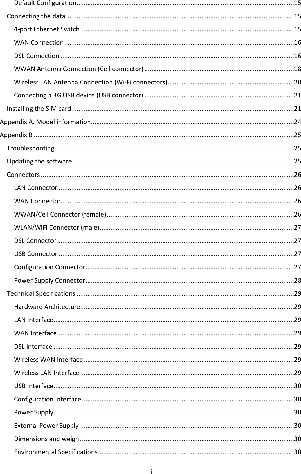
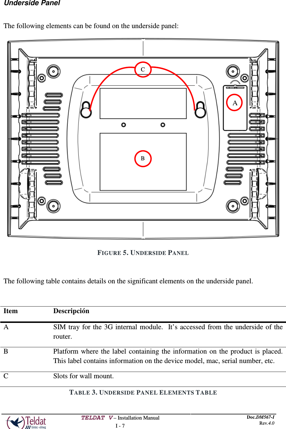
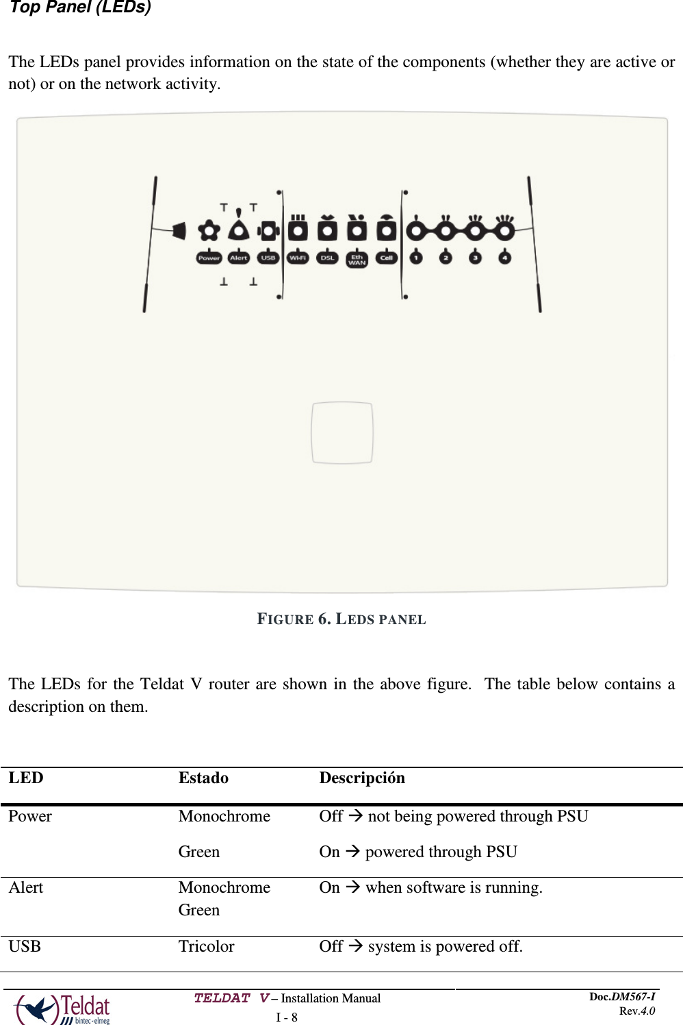
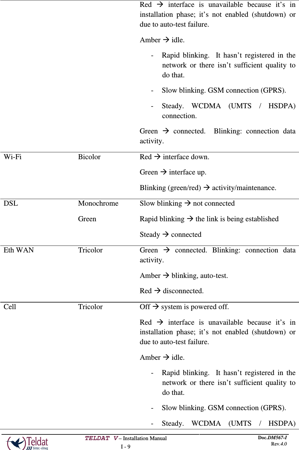
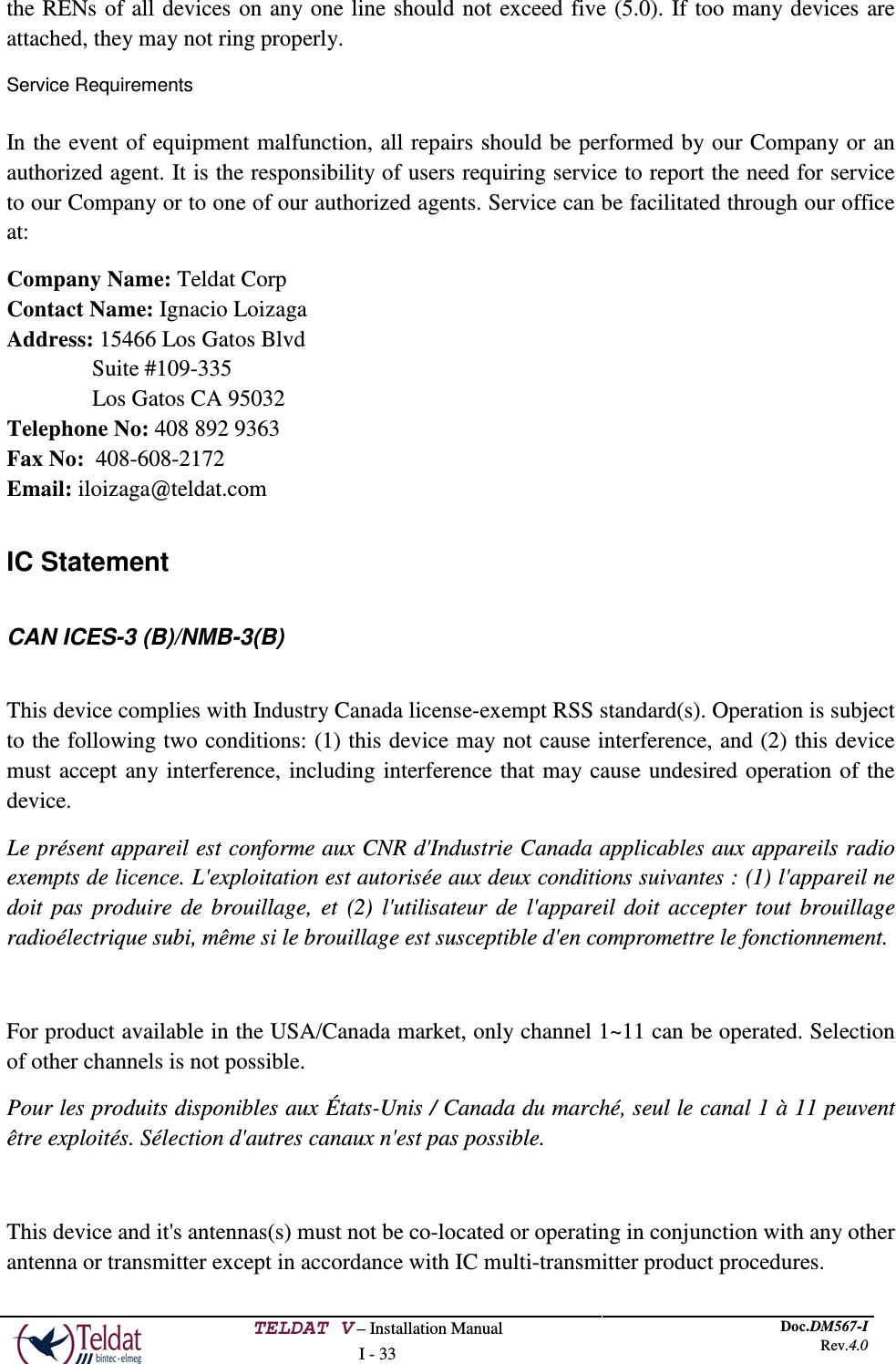
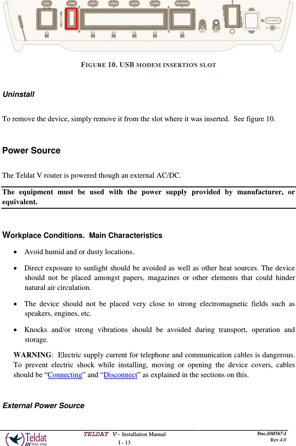
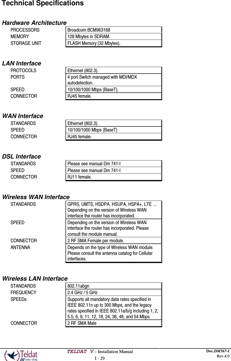
![TELDAT V – Installation Manual I - 10 Doc.DM567-I Rev.4.0 connection. Green connected. Blinking: connection data activity. Cobertura (1, 2, 3, 4) Monochrome blue Indicates the coverage level the 3G internal module has. 0 level (all LEDs off) to 4 (all LEDs on). TABLE 4. LEDS TABLE Mounting in rack The Teldat V router cannot be mounted in a rack. However there are other types of mounting. Standalone The Teldat V router can be placed as a standalone on a flat, stable surface. You need to make sure that there is enough space around the router for ventilation purposes and ensure that the electricity cables can reach it. Wall mounting The Teldat V can be mounted on the wall. There are two slots on the underside of the device which are used to fix it to the wall. You can see this in the section on the “Underside panel”. You must provide the screws and wall anchors. We recommend the following accessories for wall mounting, valid for solid wall and Gypsum board (plaster) wall: • 2 screws: [COACH SCREW HEAD 90 DEGR.POZIDR. 3,5x30]](https://usermanual.wiki/Teldat/TLDPV00A1/User-Guide-2087757-Page-14.png)
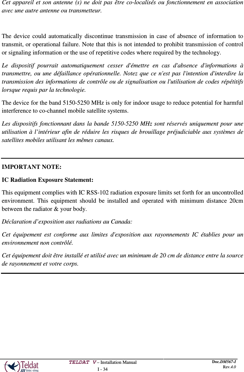
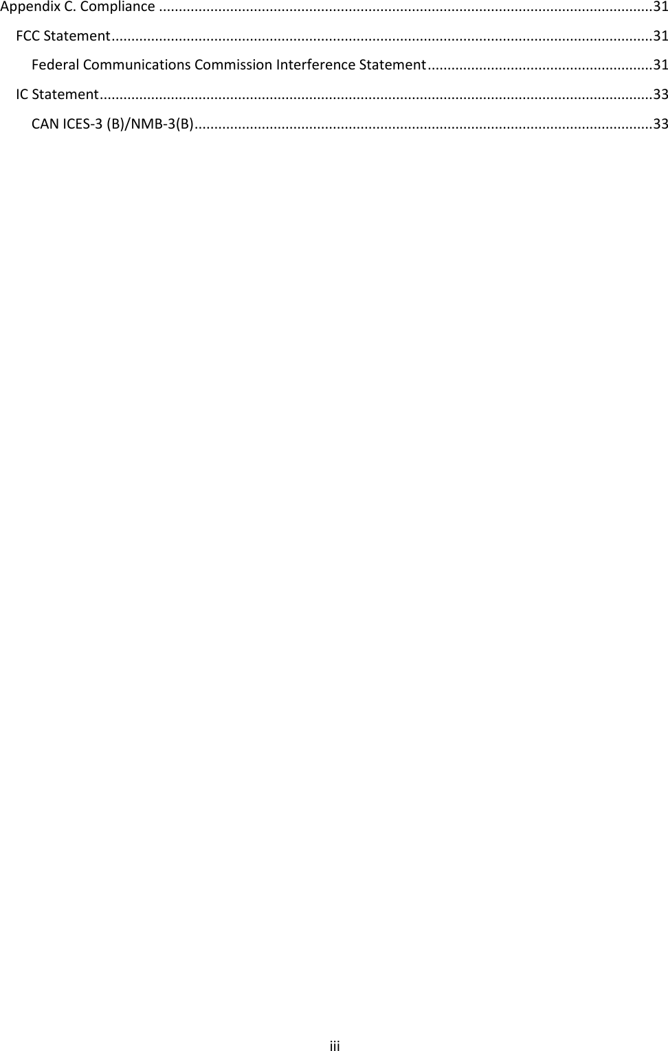
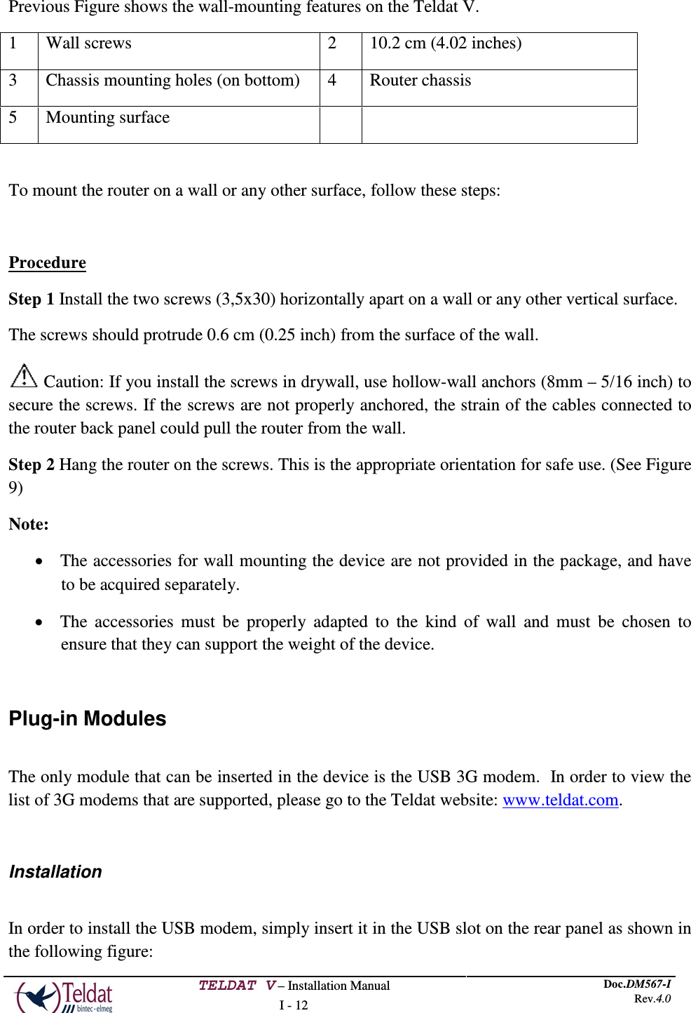
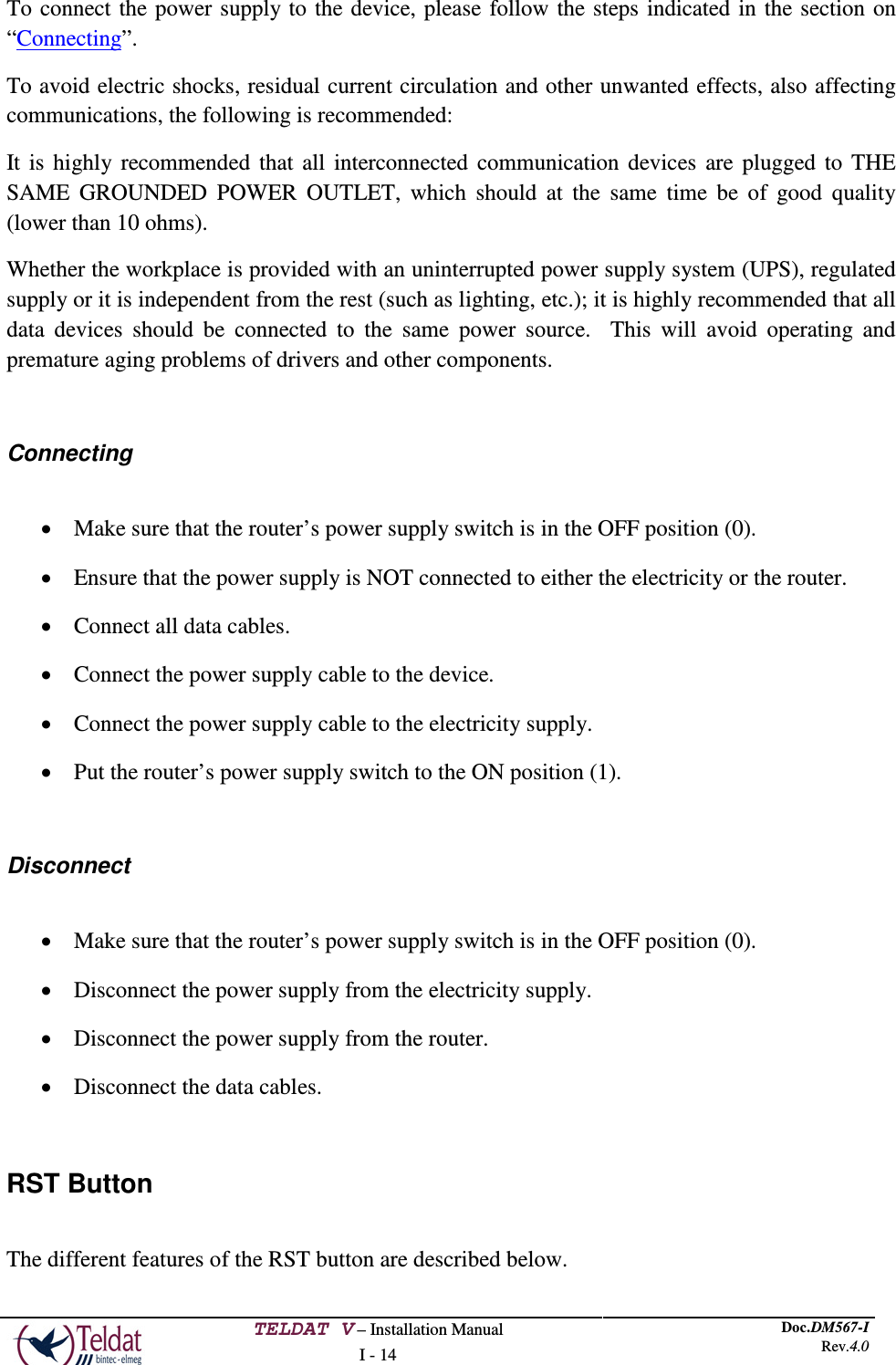
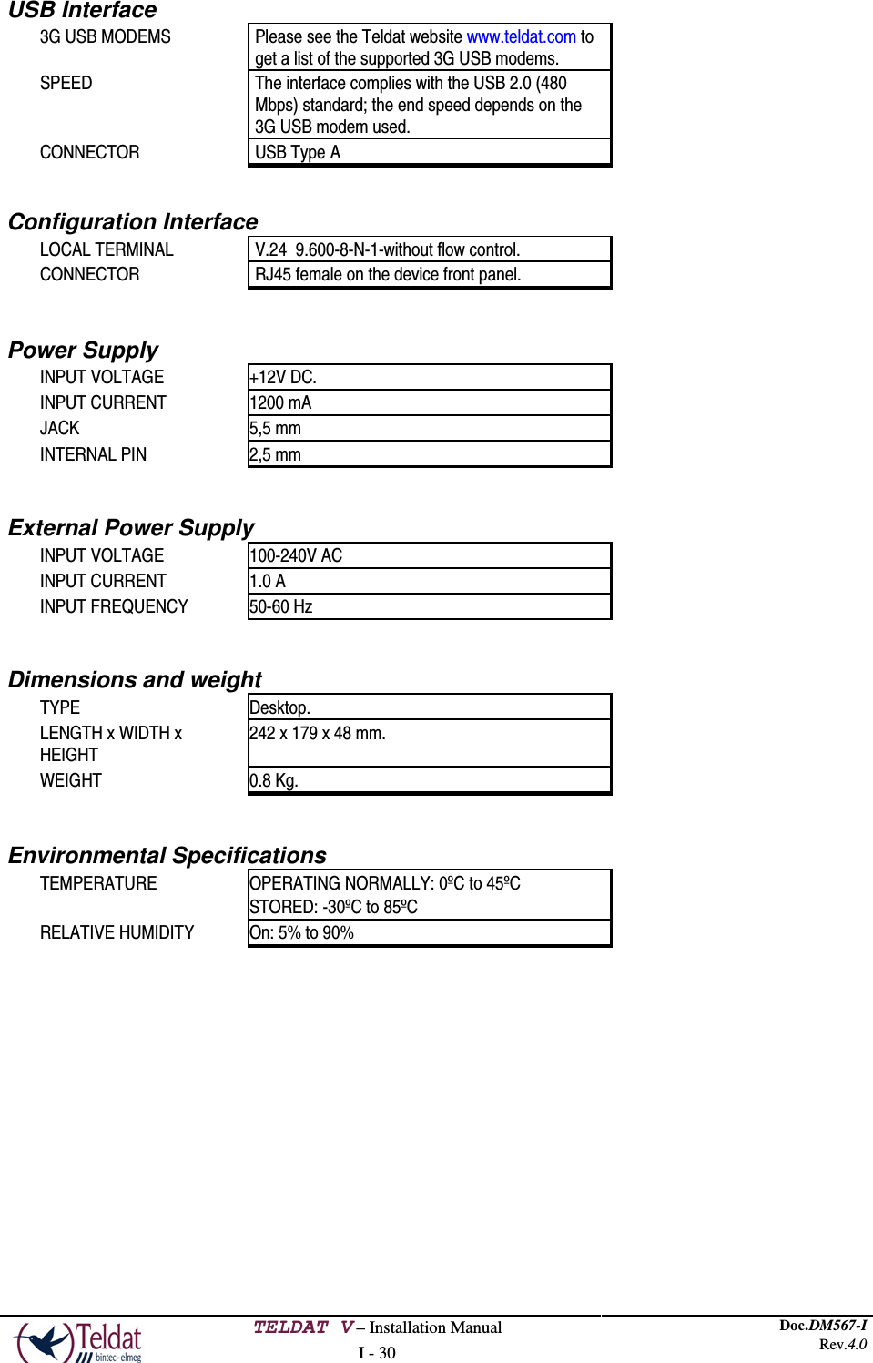
![TELDAT V – Installation Manual I - 11 Doc.DM567-I Rev.4.0 FIGURE 7. SCREW • 2 wall anchors: [WHITE STRIATED WALL ANCHOR DIAM.8mm] FIGURE 8. WALL ANCHOR Caution: The screws must go into a wall stud (wood) or a wall anchor of the appropriate type for the wall. Screws into drywall are not sufficient to mount the router. FIGURE 9. WALL-MOUNTING FEATURES ON THE TELDAT V ROUTER](https://usermanual.wiki/Teldat/TLDPV00A1/User-Guide-2087757-Page-15.png)
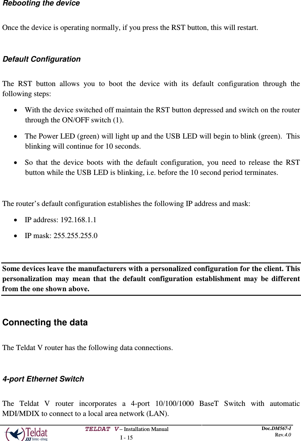
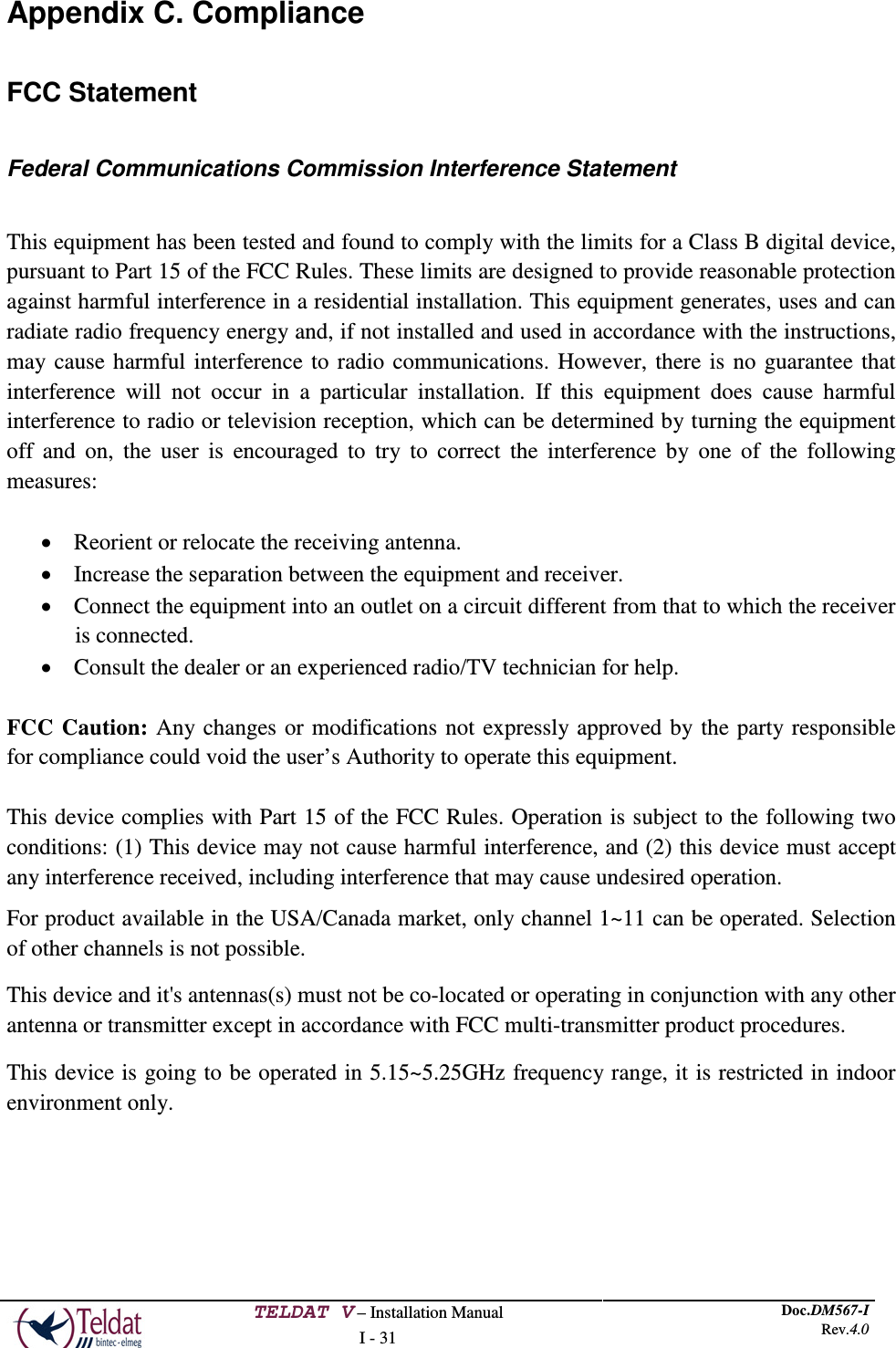
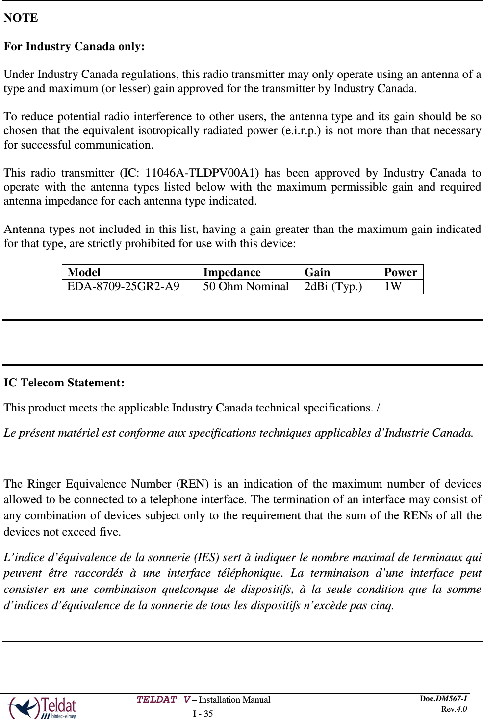
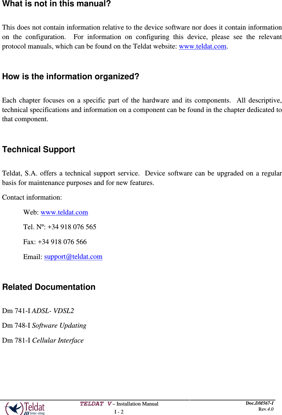
![TELDAT V – Installation Manual I - 32 Doc.DM567-I Rev.4.0 IMPORTANT NOTE: FCC Radiation Exposure Statement: This equipment complies with FCC radiation exposure limits set forth for an uncontrolled environment. This equipment should be installed and operated with minimum distance 20cm between the radiator & your body. FCC 68 Customer Information This equipment complies with Part 68 of the FCC rules and the requirements adopted by the ACTA. On bottom of this equipment is a label that contains, among other information, a product identifier of [US: TLDDL01BTLDPV00A1]. If requested, this number must be provided to the telephone company. If this equipment [Enterprise Router] causes harm to the telephone network, the telephone company will notify you in advance that temporary discontinuance of service may be required. But if advance notice isn't practical, the telephone company will notify the customer as soon as possible. Also, you will be advised of your right to file a complaint with the FCC if you believe it is necessary. The telephone company may make changes in its facilities, equipment, operations or procedures that could affect the operation of the equipment. If this happens the telephone company will provide advance notice in order for you to make necessary modifications to maintain uninterrupted service. If you experience trouble with this equipment, you disconnect it from the network until the problem has been corrected or until you are sure that the equipment is not malfunctioning. Please follow instructions for repairing if any (e.g. battery replacement section); otherwise do not alternate or repair any parts of device except specified. If the telephone company requests information on what equipment is connected to their lines, inform them of: (a) The telephone number that this unit is connected to, (b) The ringer equivalence number [01] (c) The USOC jack required [RJ11C], and (d) The FCC Registration Number [TLD] Items (b) and (d) are indicated on the label. The ringer equivalence number (REN) is used to determine how many devices can be connected to your telephone line. In most areas, the sum of](https://usermanual.wiki/Teldat/TLDPV00A1/User-Guide-2087757-Page-36.png)