user manual

TELDAT V ROUTER
Installation Manual
Doc. Dm567-I Rev. 4.0
September, 2013

i
Contents
About This Manual ........................................................................................................................................ 1
Supported Devices .................................................................................................................................... 1
Who should read this manual? ................................................................................................................. 1
When should this manual be read? .......................................................................................................... 1
What is in this manual? ............................................................................................................................. 1
What is not in this manual? ...................................................................................................................... 2
How is the information organized? ........................................................................................................... 2
Technical Support ...................................................................................................................................... 2
Related Documentation ............................................................................................................................ 2
Teldat V Router ............................................................................................................................................. 3
Features ..................................................................................................................................................... 3
Power supply ......................................................................................................................................... 3
Hardware Monitoring ............................................................................................................................ 3
Components and Power Supply .................................................................................................................... 4
Components .............................................................................................................................................. 5
Front Panel ............................................................................................................................................ 5
Rear Panel ............................................................................................................................................. 5
Side Panels ............................................................................................................................................ 6
Underside Panel .................................................................................................................................... 7
Top Panel (LEDs) .................................................................................................................................... 8
Mounting in rack ..................................................................................................................................... 10
Standalone .......................................................................................................................................... 10
Wall mounting ..................................................................................................................................... 10
Plug-in Modules ...................................................................................................................................... 12
Installation ........................................................................................................................................... 12
Uninstall .............................................................................................................................................. 13
Power Source .......................................................................................................................................... 13
External Power Source ........................................................................................................................ 13
Connecting .......................................................................................................................................... 14
Disconnect ........................................................................................................................................... 14
RST Button ............................................................................................................................................... 14
Rebooting the device .......................................................................................................................... 15
ii
Default Configuration .......................................................................................................................... 15
Connecting the data ................................................................................................................................ 15
4-port Ethernet Switch ........................................................................................................................ 15
WAN Connection ................................................................................................................................. 16
DSL Connection ................................................................................................................................... 16
WWAN Antenna Connection (Cell connector) .................................................................................... 18
Wireless LAN Antenna Connection (Wi-Fi connectors) ....................................................................... 20
Connecting a 3G USB device (USB connector) .................................................................................... 21
Installing the SIM card ............................................................................................................................. 21
Appendix A. Model information .................................................................................................................. 24
Appendix B .................................................................................................................................................. 25
Troubleshooting ...................................................................................................................................... 25
Updating the software ............................................................................................................................ 25
Connectors .............................................................................................................................................. 26
LAN Connector .................................................................................................................................... 26
WAN Connector................................................................................................................................... 26
WWAN/Cell Connector (female) ......................................................................................................... 26
WLAN/WiFi Connector (male) ............................................................................................................. 27
DSL Connector ..................................................................................................................................... 27
USB Connector .................................................................................................................................... 27
Configuration Connector ..................................................................................................................... 27
Power Supply Connector ..................................................................................................................... 28
Technical Specifications .......................................................................................................................... 29
Hardware Architecture ........................................................................................................................ 29
LAN Interface ....................................................................................................................................... 29
WAN Interface ..................................................................................................................................... 29
DSL Interface ....................................................................................................................................... 29
Wireless WAN Interface ...................................................................................................................... 29
Wireless LAN Interface ........................................................................................................................ 29
USB Interface ....................................................................................................................................... 30
Configuration Interface ....................................................................................................................... 30
Power Supply ....................................................................................................................................... 30
External Power Supply ........................................................................................................................ 30
Dimensions and weight ....................................................................................................................... 30
Environmental Specifications .............................................................................................................. 30
iii
Appendix C. Compliance ............................................................................................................................. 31
FCC Statement ......................................................................................................................................... 31
Federal Communications Commission Interference Statement ......................................................... 31
IC Statement ............................................................................................................................................ 33
CAN ICES-3 (B)/NMB-3(B) .................................................................................................................... 33

TELDAT V – Installation Manual
I - 1
Doc.DM567-I
Rev.4.0
About This Manual
This is the installation manual for the Teldat V router and contains information to correctly
install this device in a working environment.
Supported Devices
The information contained in this installation manual only applies to the Teldat V router, models
TLDPV00A1 / TLDPV01A1 / TLDPV02A1 / TLDPV03A1 / TLDPV04A1.
Who should read this manual?
This manual should be read by the support personnel who need to install, configure, maintain
and monitor the device.
When should this manual be read?
Read this guide as soon as you are ready to familiarize yourself with the device and its
components.
This manual will help you understand your new device in greater depth.
What is in this manual?
This installation guide contains the following information:
• Description of the available features in the Teldat V.
• Technical specifications.
• Power supply requirements.
• Elements you can connect to the device while it is running.
• Installation and removal procedures for modules and power supplies.
• Description of the device LEDs and the connectors.
• Troubleshooting.

TELDAT V – Installation Manual
I - 2
Doc.DM567-I
Rev.4.0
What is not in this manual?
This does not contain information relative to the device software nor does it contain information
on the configuration. For information on configuring this device, please see the relevant
protocol manuals, which can be found on the Teldat website: www.teldat.com.
How is the information organized?
Each chapter focuses on a specific part of the hardware and its components. All descriptive,
technical specifications and information on a component can be found in the chapter dedicated to
that component.
Technical Support
Teldat, S.A. offers a technical support service. Device software can be upgraded on a regular
basis for maintenance purposes and for new features.
Contact information:
Web: www.teldat.com
Tel. Nº: +34 918 076 565
Fax: +34 918 076 566
Email: support@teldat.com
Related Documentation
Dm 741-I ADSL- VDSL2
Dm 748-I Software Updating
Dm 781-I Cellular Interface

TELDAT V – Installation Manual
I - 3
Doc.DM567-I
Rev.4.0
Teldat V Router
Features
Power supply
For further information on the power supply in the Teldat V router, please see the chapter on
“Components and power supplies”, in the section on “Power Source”.
Hardware Monitoring
The only way to monitor the Teldat V router hardware is through the LEDs panel. The LEDs
provide visual information on what is happening in the device. These indicate the state of the
hardware components, if there is connectivity, data flow, etc.
For further information on the LEDs panel, please see the section on “Components” in the
following chapter.

TELDAT V – Installation Manual
I - 4
Doc.DM567-I
Rev.4.0
Components and Power Supply
The following chapter provides detailed information on the chassis of the Teldat V router and its
components. This information includes:
• Components.
• Information on assembly.
• Installation and removal of modules.
• Power supply.
• RST button.
• Data connection.
• SIM card installation.
TELDAT V – Installation Manual
I - 5
Doc.DM567-I
Rev.4.0
Components
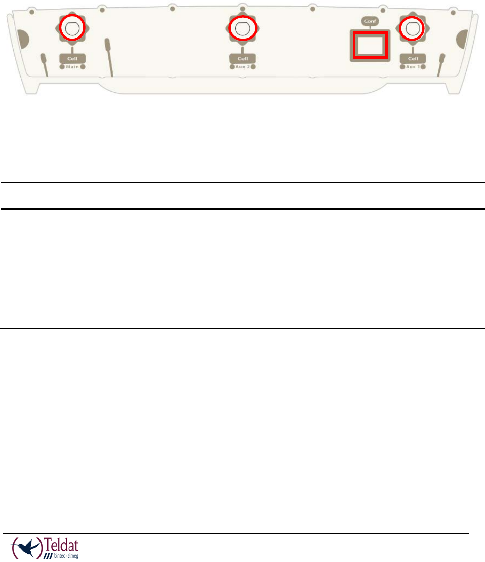
Front Panel
The following figure shows the front panel. The only thing to be found here are the 3G antenna
connectors.
FIGURE 1. FRONT PANEL
The front panel elements are as follows:
Item
Description
A
Main antenna for the Teldat V cellular module.
B
Auxiliary antenna 2 for the Teldat V cellular module.
C
Auxiliary antenna 1 for the Teldat V cellular module.
D
RJ-45 connector to provide access to the Teldat V local console for configuring
and monitoring purposes.
TABLE 1. FRONT PANEL ELEMENTS
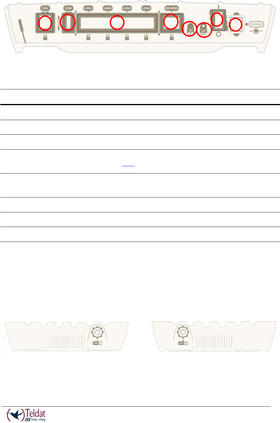
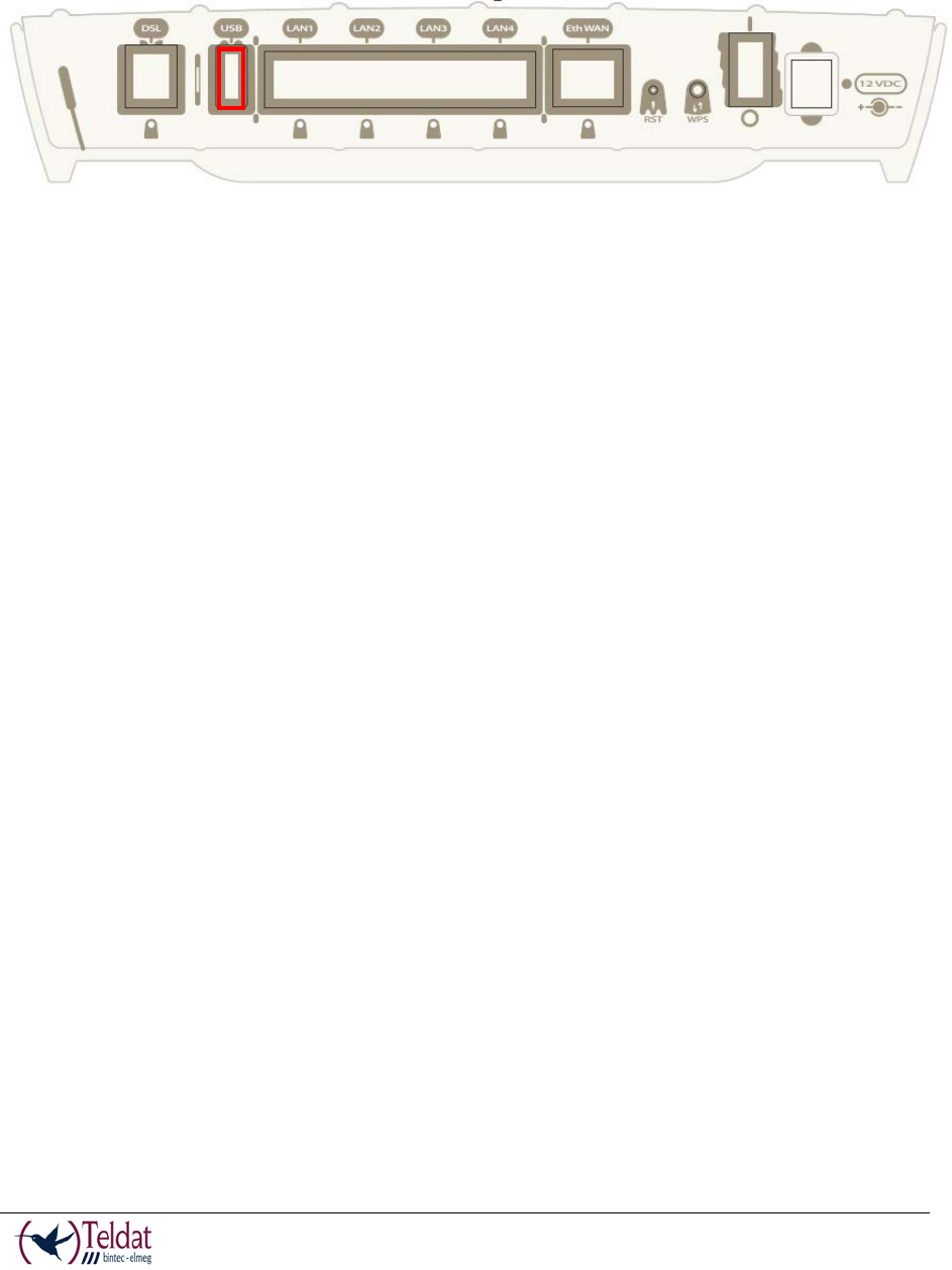
Rear Panel
The following figure shows the rear panel. Here you can see the rest of connectors for the Teldat
V router.
A
B
C
D
TELDAT V – Installation Manual
I - 6
Doc.DM567-I
Rev.4.0
FIGURE 2. REAR PANEL
The following table provides information on each connector as well as a description:
Item
Descripción
A
DSL. DSL connector.
B
USB. Slot where you can insert a 3G USB modem.
C
4-port Gigabit Ethernet Switch.
D
RST. Reset button. For further information on how the reset button works,
please see the section on “RST Button” in this chapter.
E
WPS (Wireless Protected Setup). This allows for easy and secure configuration
of the WiFi network parameters.
F
Eth WAN. WAN Gigabit Ethernet.
G
On/Off switch.
H
Power source connection (PSU).
TABLE 2. REAR PANEL ELEMENTS
Side Panels
Two WiFi antennas are located on the side panels, one on either side.
FIGURE 3. RIGHT HAND SIDE PANEL
FIGURE 4. LEFT HAND SIDE PANEL
A
B
C
D
E
F
G
H
TELDAT V – Installation Manual
I - 7
Doc.DM567-I
Rev.4.0
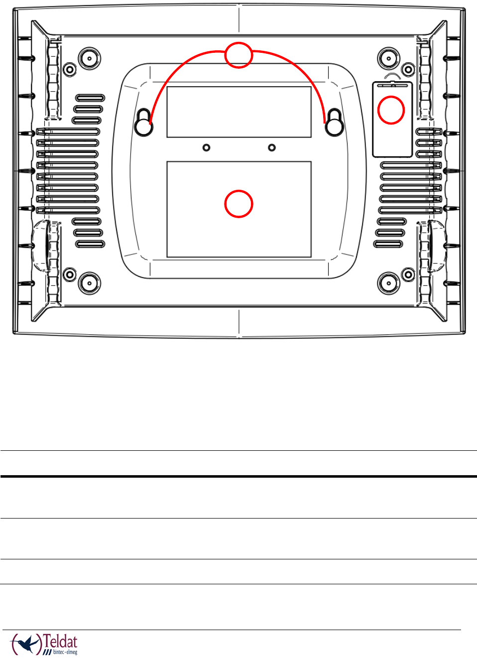
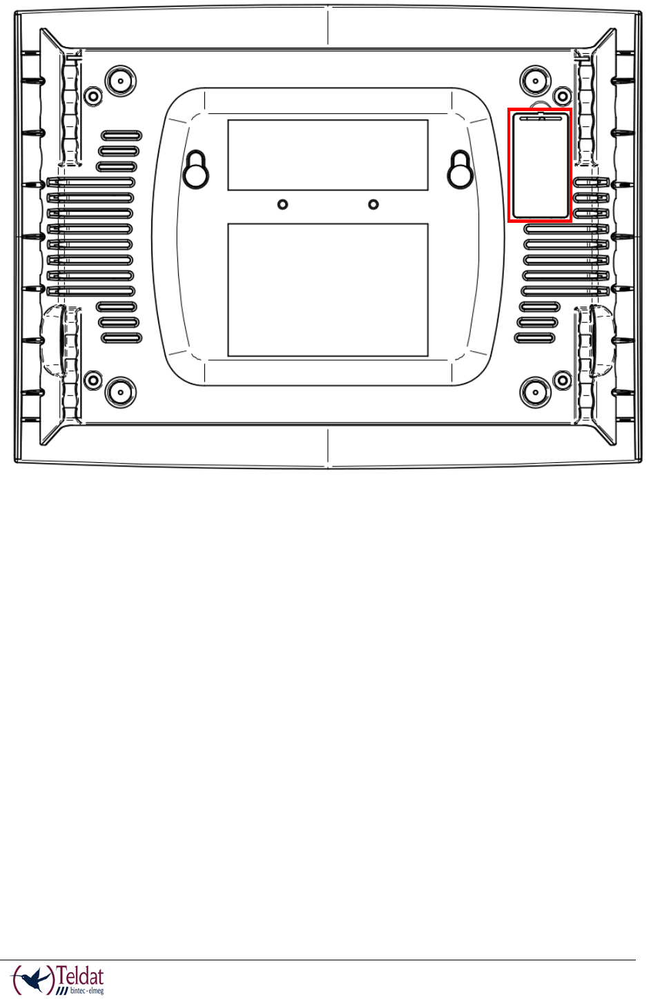
Underside Panel
The following elements can be found on the underside panel:
FIGURE 5. UNDERSIDE PANEL
The following table contains details on the significant elements on the underside panel.
Item
Descripción
A
SIM tray for the 3G internal module. It’s accessed from the underside of the
router.
B
Platform where the label containing the information on the product is placed.
This label contains information on the device model, mac, serial number, etc.
C
Slots for wall mount.
TABLE 3. UNDERSIDE PANEL ELEMENTS TABLE
B
A
C
TELDAT V – Installation Manual
I - 8
Doc.DM567-I
Rev.4.0
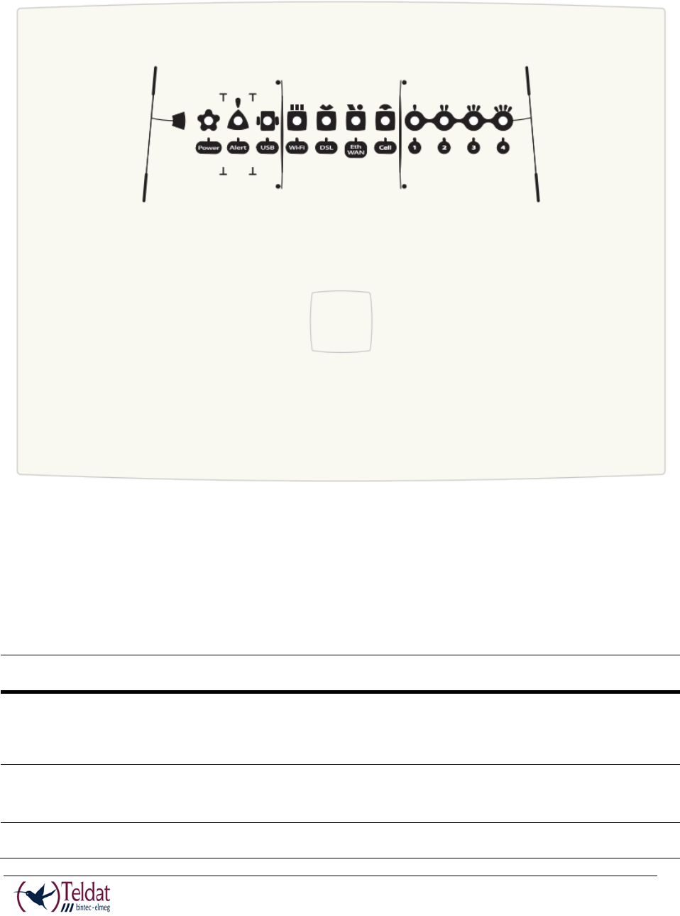
Top Panel (LEDs)
The LEDs panel provides information on the state of the components (whether they are active or
not) or on the network activity.
FIGURE 6. LEDS PANEL
The LEDs for the Teldat V router are shown in the above figure. The table below contains a
description on them.
LED
Estado
Descripción
Power
Monochrome
Green
Off
not being powered through PSU
On powered through PSU
Alert
Monochrome
Green
On
when software is running.
USB
Tricolor
Off system is powered off.

TELDAT V – Installation Manual
I - 9
Doc.DM567-I
Rev.4.0
Red interface is unavailable because it’s in
installation phase; it’s not enable
d (shutdown) or
due to auto-test failure.
Amber idle.
- Rapid blinking. It hasn’t registered in the
network or there isn’t sufficient quality to
do that.
- Slow blinking. GSM connection (GPRS).
- Steady. WCDMA (UMTS / HSDPA)
connection.
Green connected. Bl
inking: connection data
activity.
Wi-Fi
Bicolor
Red interface down.
Green interface up.
Blinking (green/red) activity/maintenance.
DSL
Monochrome
Green
Slow blinking not connected
Rapid blinking the link is being established
Steady connected
Eth WAN
Tricolor
Green connected. Blinking: connection data
activity.
Amber blinking, auto-test.
Red disconnected.
Cell
Tricolor
Off
system is powered off.
Red
interface is unavailable because it’s in
installation phase; it’s not enabled (shut
down) or
due to auto-test failure.
Amber idle.
- Rapid blinking. It hasn’t registered in the
network or there isn’t sufficient quality to
do that.
- Slow blinking. GSM connection (GPRS).
- Steady. WCDMA (UMTS / HSDPA)

TELDAT V – Installation Manual
I - 10
Doc.DM567-I
Rev.4.0
connection.
Green connected. Blinking:
connection data
activity.
Cobertura
(1, 2, 3, 4)
Monochrome
blue
Indicates the coverage level the 3G internal module
has. 0 level (all LEDs off) to 4 (all LEDs on).
TABLE 4. LEDS TABLE
Mounting in rack
The Teldat V router cannot be mounted in a rack. However there are other types of mounting.
Standalone
The Teldat V router can be placed as a standalone on a flat, stable surface.
You need to make sure that there is enough space around the router for ventilation purposes and
ensure that the electricity cables can reach it.
Wall mounting
The Teldat V can be mounted on the wall.
There are two slots on the underside of the device which are used to fix it to the wall. You can
see this in the section on the “Underside panel”.
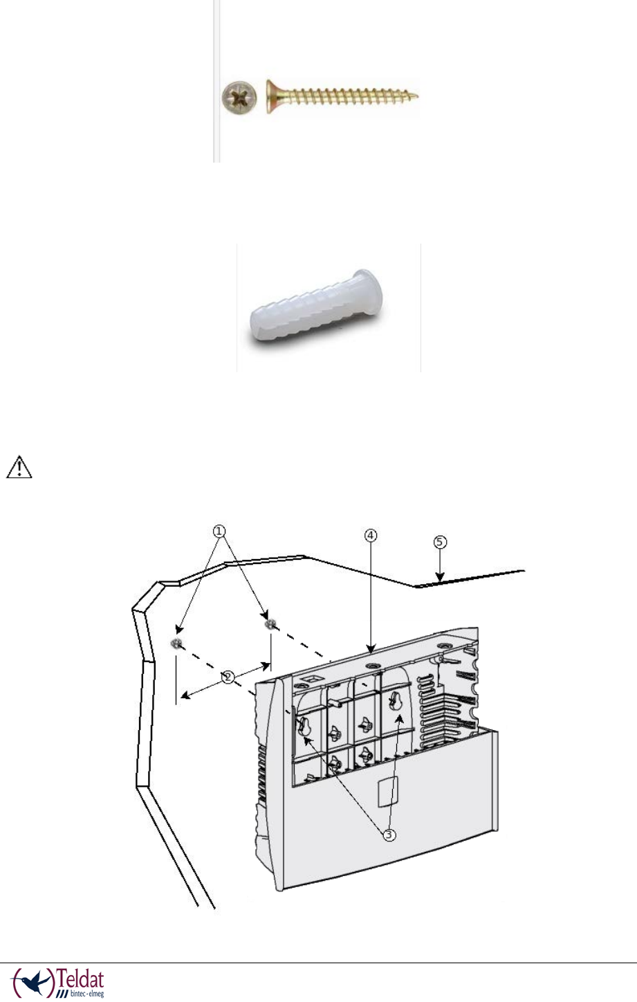
You must provide the screws and wall anchors. We recommend the following accessories for
wall mounting, valid for solid wall and Gypsum board (plaster) wall:
• 2 screws: [COACH SCREW HEAD 90 DEGR.POZIDR. 3,5x30]
TELDAT V – Installation Manual
I - 11
Doc.DM567-I
Rev.4.0
FIGURE 7. SCREW
• 2 wall anchors: [WHITE STRIATED WALL ANCHOR DIAM.8mm]
FIGURE 8. WALL ANCHOR
Caution: The screws must go into a wall stud (wood) or a wall anchor of the appropriate
type for the wall. Screws into drywall are not sufficient to mount the router.
FIGURE 9. WALL-MOUNTING FEATURES ON THE TELDAT V ROUTER
TELDAT V – Installation Manual
I - 12
Doc.DM567-I
Rev.4.0
Previous Figure shows the wall-mounting features on the Teldat V.
1
Wall screws
2
10.2 cm (4.02 inches)
3
Chassis mounting holes (on bottom)
4
Router chassis
5
Mounting surface
To mount the router on a wall or any other surface, follow these steps:
Procedure
Step 1 Install the two screws (3,5x30) horizontally apart on a wall or any other vertical surface.
The screws should protrude 0.6 cm (0.25 inch) from the surface of the wall.
Caution: If you install the screws in drywall, use hollow-wall anchors (8mm – 5/16 inch) to
secure the screws. If the screws are not properly anchored, the strain of the cables connected to
the router back panel could pull the router from the wall.
Step 2 Hang the router on the screws. This is the appropriate orientation for safe use. (See Figure
9)
Note:
• The accessories for wall mounting the device are not provided in the package, and have
to be acquired separately.
• The accessories must be properly adapted to the kind of wall and must be chosen to
ensure that they can support the weight of the device.
Plug-in Modules
The only module that can be inserted in the device is the USB 3G modem. In order to view the
list of 3G modems that are supported, please go to the Teldat website: www.teldat.com.
Installation
In order to install the USB modem, simply insert it in the USB slot on the rear panel as shown in
the following figure:
TELDAT V – Installation Manual
I - 13
Doc.DM567-I
Rev.4.0
FIGURE 10. USB MODEM INSERTION SLOT
Uninstall
To remove the device, simply remove it from the slot where it was inserted. See figure 10.
Power Source
The Teldat V router is powered though an external AC/DC.
The equipment must be used with the power supply provided by manufacturer, or
equivalent.
Workplace Conditions. Main Characteristics
• Avoid humid and or dusty locations.
• Direct exposure to sunlight should be avoided as well as other heat sources. The device
should not be placed amongst papers, magazines or other elements that could hinder
natural air circulation.
• The device should not be placed very close to strong electromagnetic fields such as
speakers, engines, etc.
• Knocks and/or strong vibrations should be avoided during transport, operation and
storage.
WARNING: Electric supply current for telephone and communication cables is dangerous.
To prevent electric shock while installing, moving or opening the device covers, cables
should be “Connecting” and “Disconnect” as explained in the sections on this.
External Power Source

TELDAT V – Installation Manual
I - 14
Doc.DM567-I
Rev.4.0
To connect the power supply to the device, please follow the steps indicated in the section on
“Connecting”.
To avoid electric shocks, residual current circulation and other unwanted effects, also affecting
communications, the following is recommended:
It is highly recommended that all interconnected communication devices are plugged to THE
SAME GROUNDED POWER OUTLET, which should at the same time be of good quality
(lower than 10 ohms).
Whether the workplace is provided with an uninterrupted power supply system (UPS), regulated
supply or it is independent from the rest (such as lighting, etc.); it is highly recommended that all
data devices should be connected to the same power source. This will avoid operating and
premature aging problems of drivers and other components.
Connecting
• Make sure that the router’s power supply switch is in the OFF position (0).
• Ensure that the power supply is NOT connected to either the electricity or the router.
• Connect all data cables.
• Connect the power supply cable to the device.
• Connect the power supply cable to the electricity supply.
• Put the router’s power supply switch to the ON position (1).
Disconnect
• Make sure that the router’s power supply switch is in the OFF position (0).
• Disconnect the power supply from the electricity supply.
• Disconnect the power supply from the router.
• Disconnect the data cables.
RST Button
The different features of the RST button are described below.

TELDAT V – Installation Manual
I - 15
Doc.DM567-I
Rev.4.0
Rebooting the device
Once the device is operating normally, if you press the RST button, this will restart.
Default Configuration
The RST button allows you to boot the device with its default configuration through the
following steps:
• With the device switched off maintain the RST button depressed and switch on the router
through the ON/OFF switch (1).
• The Power LED (green) will light up and the USB LED will begin to blink (green). This
blinking will continue for 10 seconds.
• So that the device boots with the default configuration, you need to release the RST
button while the USB LED is blinking, i.e. before the 10 second period terminates.
The router’s default configuration establishes the following IP address and mask:
• IP address: 192.168.1.1
• IP mask: 255.255.255.0
Some devices leave the manufacturers with a personalized configuration for the client. This
personalization may mean that the default configuration establishment may be different
from the one shown above.
Connecting the data
The Teldat V router has the following data connections.
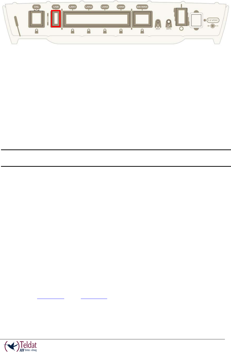
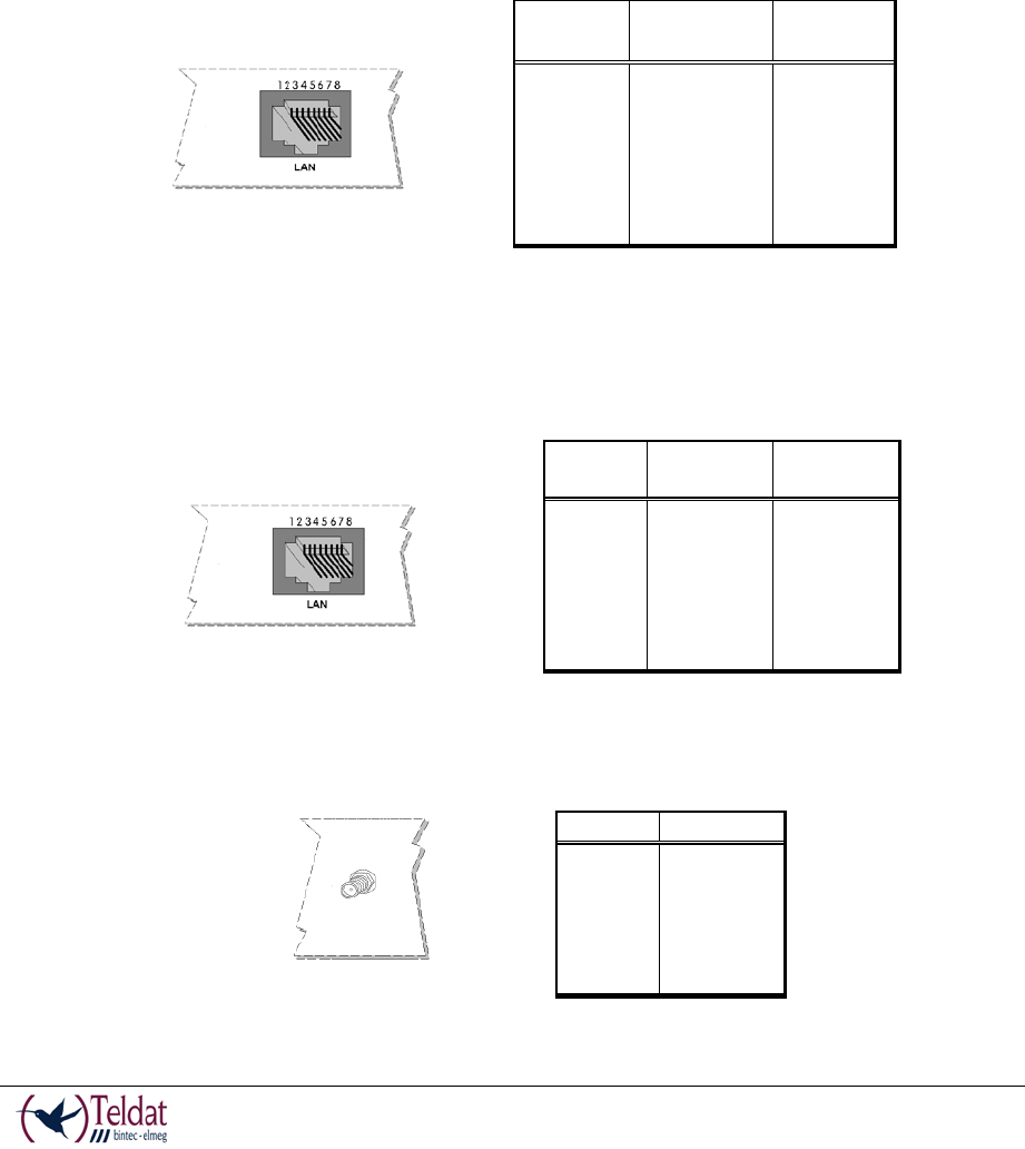
4-port Ethernet Switch
The Teldat V router incorporates a 4-port 10/100/1000 BaseT Switch with automatic
MDI/MDIX to connect to a local area network (LAN).
TELDAT V – Installation Manual
I - 16
Doc.DM567-I
Rev.4.0
Please pay careful attention to the labeling so you do not confuse this switch with other types of
ports:
FIGURE 11. LAN SWITCH PORTS
During booting and in BIOS mode, only the LAN 1 connector is available.
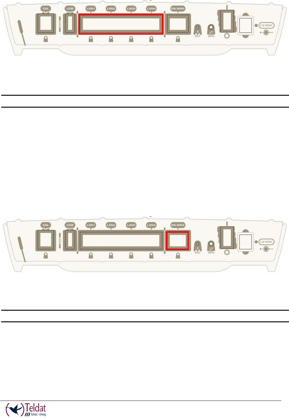
WAN Connection
The Teldat V incorporates an Ethernet WAN 10/100/1000 BaseT port with automatic
MDI/MDIX.
The WAN port is independent to the Switch and is handled as just one more interface.
Please pay careful attention to the labeling so you do not confuse this switch with other types of
ports:
FIGURE 12. WAN PORT
During booting and in BIOS mode, the Eth WAN connector is not operative.
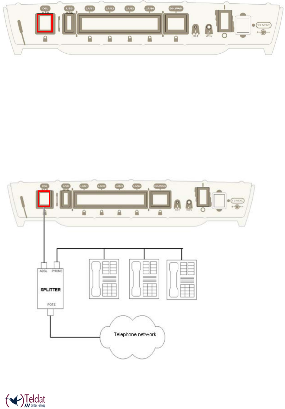
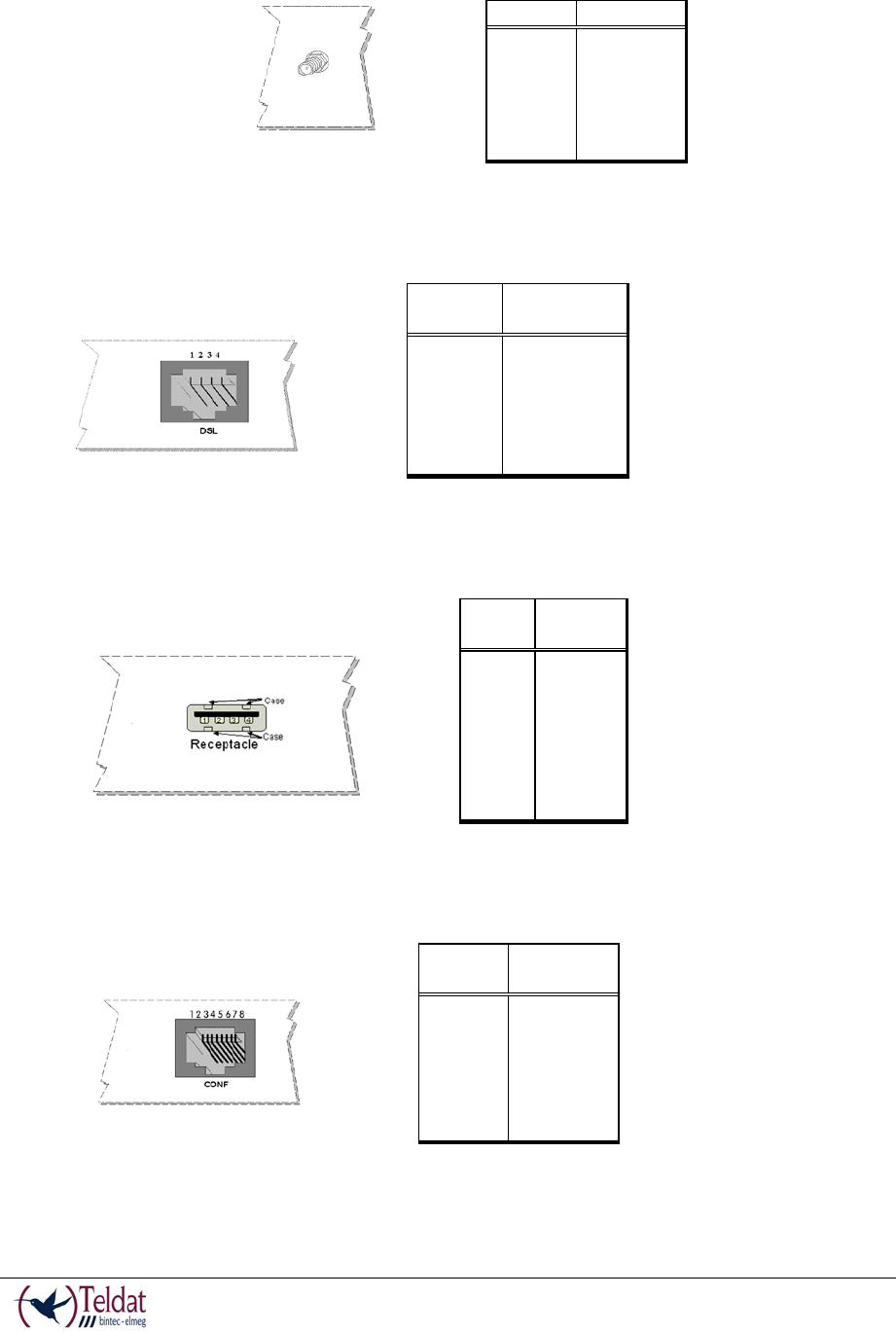
DSL Connection
The Teldat V has a DSL connector to connect to a VSDL2/ADSL network. This is a 4-wire
female RJ11 connector where the central pair is used for data transmission/reception.
For connection you can use the telephone cable with male RJ11 connectors that are provided
TELDAT V – Installation Manual
I - 17
Doc.DM567-I
Rev.4.0
with the device.
FIGURE 13. DSL PORT (VDSL2/ADSL)
The splitter
By default, the supported modes do not allow the use of the basic service device (PSTN or ISDN
depending on the model) directly connected to the same line; you need to use a device known as
a “splitter”, which separates the basic service frequencies band from those used by the DSL
connection, thus avoiding interferences between the telephone service and DSL service.
A typical installation with a splitter is shown in figure 14.
FIGURE 14. ADSL INSTALLATION WITHS PLITTER
TELDAT V – Installation Manual
I - 18
Doc.DM567-I
Rev.4.0
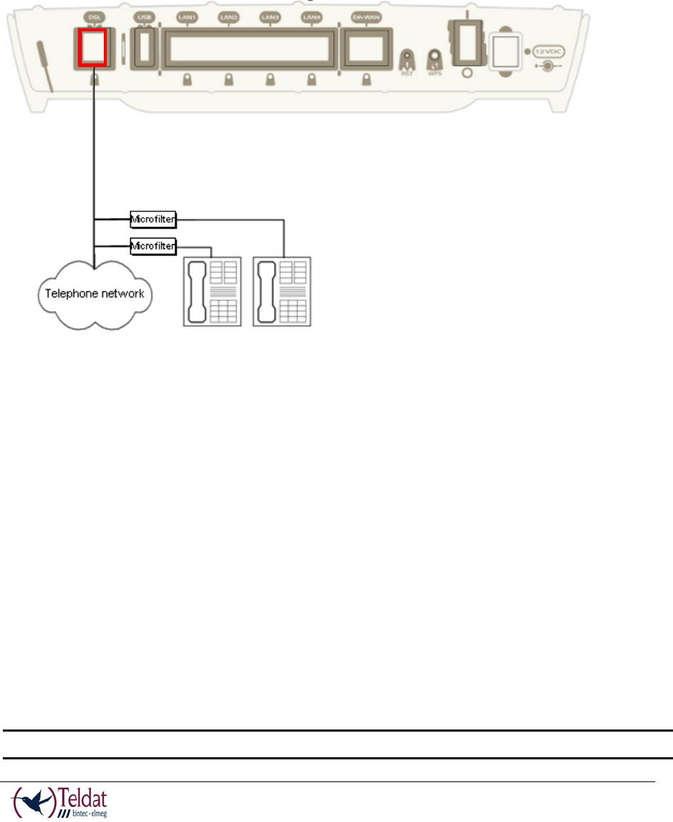
The micro-filters
Only some DSL operating modes (eg, G.Lite or ITU G.922.2) permit the use of basic service
devices (PSTN or ISDN) directly connected to the same line by using a device called “micro-
filter”. This device ensures that the DSL signal does not reach the basic service device and that
undesired signals generated by the device do not interfere with the DSL signal.
A typical installation with micro-filters is shown in figure 15.
FIGURE 15. ADSL INSTALLATION WITH MICROFILTERS
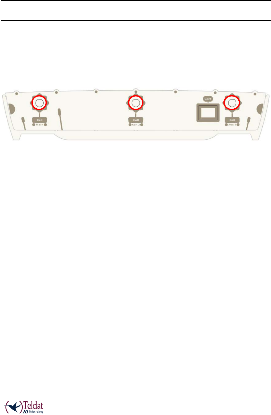
WWAN Antenna Connection (Cell connector)
The Teldat V router has three connectors to connect 3G antennas. To assemble and disassemble
the antennas, simply screw them into the connectors labeled Cell on the front panel of the router.
The installation of these antennas in the Teldat V router is essential in order to improve the
quality of the signal received and transmitted by the cellular model.
So that the Wireless WAN interface is operative, the device must have a plug-in Wireless WAN
card and the corresponding software license. If your device does not have the Wireless WAN
module incorporated, you can obtain this later on. The manual accompanying this module will
indicate how to install it as well as the corresponding antenna cables in the device.
To obtain good performance, the router should always have the WWAN antennas installed.
TELDAT V – Installation Manual
I - 19
Doc.DM567-I
Rev.4.0
So the cellular interface is operative, the router must have the corresponding software
license incorporated.
Some cellular telephony technologies use the antenna diversity technique to improve the quality
of the received signal (HSUPA, CDMA EV-DO, etc.). Due to this the Teldat V router
incorporates various WWAN connectors
FIGURE 16. WWAN ANTENNAS
When the Main and Aux 1 antennas are not installed directly connected to the router but through
extension cords, the minimum distance between the two of them must be 7cm. The maximum
recommended distance between the two is 25cm.
To achieve an optimum performance, the radio frequency accessories installed (antennas and
cables) should be those recommended by Teldat.
Teldat has a series of accessories available (90º mount antennas, antennas for exterior
installation, antennas ceiling installation, extension cables, etc) which allow you to install the
devices in different locations.
Placing the Antenna
The orientation of the antenna, its location with respect to other wireless devices or other
radiation sources such as communication devices, personal computers, etc can significantly
influence the performance level of the equipment.
The antennas transmit and receive radio signals. This performance is also affected by
environment factors such as the distance between the device and the base station, physical
obstacles and other interferences due to radiofrequencies (RF).
In order to receive better coverage, follow the instructions given below:
• Whenever possible, position the antenna in a place where there are no physical obstacles.
Obstacles between the antenna and the base station degrade the wireless signal. Place the
antenna above ground level and appropriately orientate it towards the nearest base
station.
TELDAT V – Installation Manual
I - 20
Doc.DM567-I
Rev.4.0
• The density of materials also affects the antennas. Position it away from all types of
walls, metal screens, mirrors, etc.
• Do not place the antenna near columns that could throw shadows and reduce the coverage
area.
• Keep the antenna away from metal ducts such as canalization, air-conditioning etc.
• Bear in mind that other wireless devices such as telephones, microwaves, etc can
temporarily interfere with the quality of the wireless signal.
• We do not recommend that you install antennas in racks containing communication
devices, computers, etc. Use an extension cord for this and locate the antenna outside.
The following recommendations are applicable to all wireless devices:
• Do not touch or move the antenna while the device is transmitting or receiving.
• Do not handle any equipment that contains devices which radiate so the antenna is very
close or touching any exposed part of the body, particularly the face or eyes, when it is
transmitting.
• Do not install the device in areas where the atmosphere is potentially explosive.
• Wireless devices can cause interferences with other devices. Do not use the device in
environments where medical equipment is installed.
• To ensure the R&TTE 1999/5/EC directive is complied with, the device must be at least
15 cm away from a person’s body when operating.
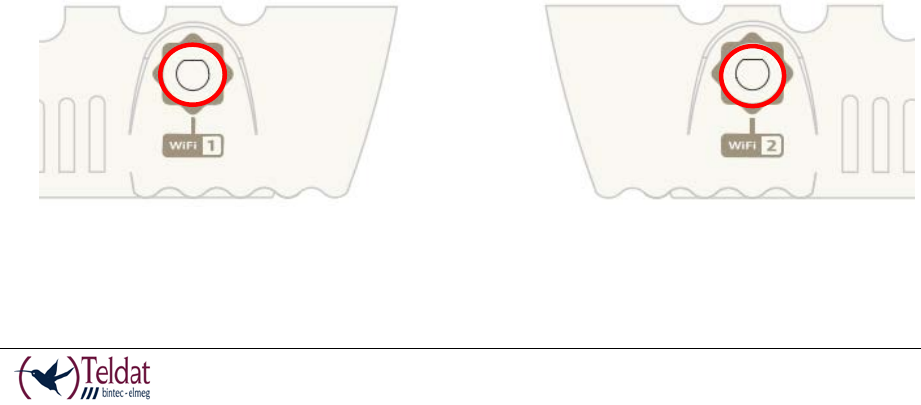
Wireless LAN Antenna Connection (Wi-Fi connectors)
The Teldat V router has two RF antenna connectors to connect an external antenna to improve
the quality of the signal received and transmitted by the Wireless LAN module.
This module is internal and can be activated by purchasing the corresponding software license.
To assemble and disassemble the antennas provided with the device, just screw them into the
connectors, labeled Wi-Fi, which are located on both lateral panels of the router.
FIGURE 17. WI-FI ANTENNA 1
FIGURE 18. WI-FI ANTENNA 2
TELDAT V – Installation Manual
I - 21
Doc.DM567-I
Rev.4.0
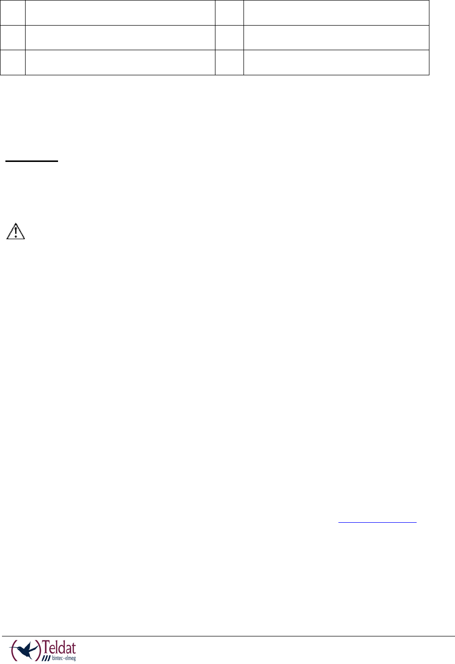
Connecting a 3G USB device (USB connector)
The Teldat V has a USB HOST 2.0 Type A connector interface which permits 3G USB modems
to be connected. The interface can be activated by purchasing the corresponding software
license.
FIGURE 19. USB 3G CONNECTOR
Installing the SIM card
The Teldat V has a Wireless WAN interface that in order to operate require one SIM card that
must be inserted into the device. There are determined services (CDMA) provided by some
carriers in certain countries that do not require SIM cards.
To access the 3G module SIM tray, you need to go to the underside of the router, open the flap
which is shown in the following figure in order to insert the SIM card.
TELDAT V – Installation Manual
I - 22
Doc.DM567-I
Rev.4.0
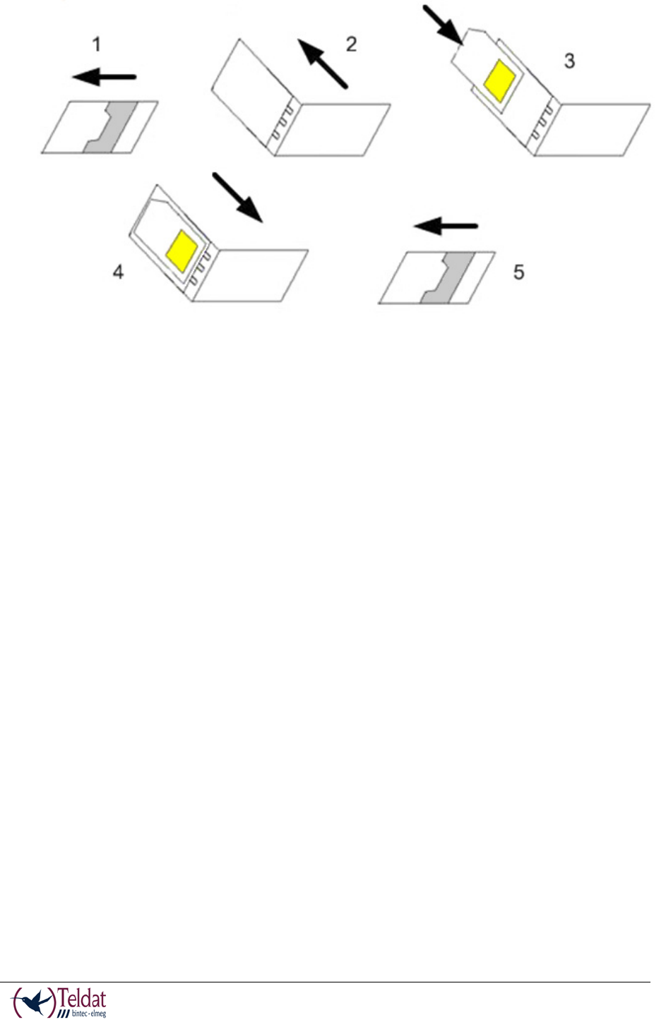
FIGURE 20. 3G MODULE SIM TRAY
You need to insert the SIM in the following way. First locate the slot and remove the flap. The
SIM tray at that point is visible. Then you need to carry out the following steps:
1. Push the fastening in the direction indicated by the labelled OPEN.
2. Open the upper part of the tray.
3. Fully insert the SIM card using the guides.
4. Return the tray to its original position
5. While pressing on the tray, push the fastening towards the inside of the tray OPEN so it is
completely held.
TELDAT V – Installation Manual
I - 23
Doc.DM567-I
Rev.4.0
FIGURE 21. INSTRUCTIONS TO INSERT THE SIM IN THE 3G MODULE

TELDAT V – Installation Manual
I - 24
Doc.DM567-I
Rev.4.0
Appendix A. Model information
Actually exists several equipments with different WWAN module configuration. Next table
shows the relation between the commercial name, regulatory model and functionality.
Part Number
Comercial Name
Regulatory Name
Description
RCTVH001 Teldat V TLDPV00A1 Teldat V: 1xVDSL2/ADSL2+, 4xGE
RCTVH003 Teldat V-H+ TLDPV01A1 Teldat V-H+: 1xVDSL2/ADSL2+, 4xGE, HSPA+
RCTVH004 Teldat V-LE TLDPV02A1 Teldat V-LE: 1xVDSL2/ADSL2+, 4xGE, LTE (Europe)
RCTVH005 Teldat V-LA TLDPV03A1 Teldat V-LA: 1xVDSL2/ADSL2+, 4xGE, LTE (AT&T)
RCTVH006 Teldat V-LV TLDPV04A1 Teldat V-LV: 1xVDSL2/ADSL2+, 4xGE, LTE (Verizon)
RCTVH101 Teldat V-GE TLDPV00A1 Teldat-V-GE: 1xGE, 4xGE
RCTVH103 Teldat V-GE-H+ TLDPV01A1 Teldat V-GE-H+: 1xGE, 4xGE, HSPA+
RCTVH104 Teldat V-GE-LE TLDPV02A1 Teldat V-GE-LE: 1xGE, 4xGE, LTE (Europe)
RCTVH105 Teldat V-GE-LA TLDPV03A1 Teldat V-GE-LA: 1xGE, 4xGE, LTE (AT&T)
RCTVH106 Teldat V-GE-LV TLDPV04A1 Teldat V-GE-LV: 1xGE, 4xGE, LTE (Verizon)
RCTVH303
Teldat VB-H+
TLDPV01A1
Teldat V VB-H+: 4xGE, HSPA+
RCTVH304
Teldat VB-LE
TLDPV02A1
Teldat VB-LE: 4xGE, LTE (Europe)
RCTVH305
Teldat VB-LA
TLDPV03A1
Teldat VB-LA: 4xGE, LTE (AT&T)
RCTVH306
Teldat VB-LV
TLDPV04A1
Teldat VB-LV: 4xGE, LTE (Verizon)
TELDAT V – Installation Manual
I - 25
Doc.DM567-I
Rev.4.0
Appendix B
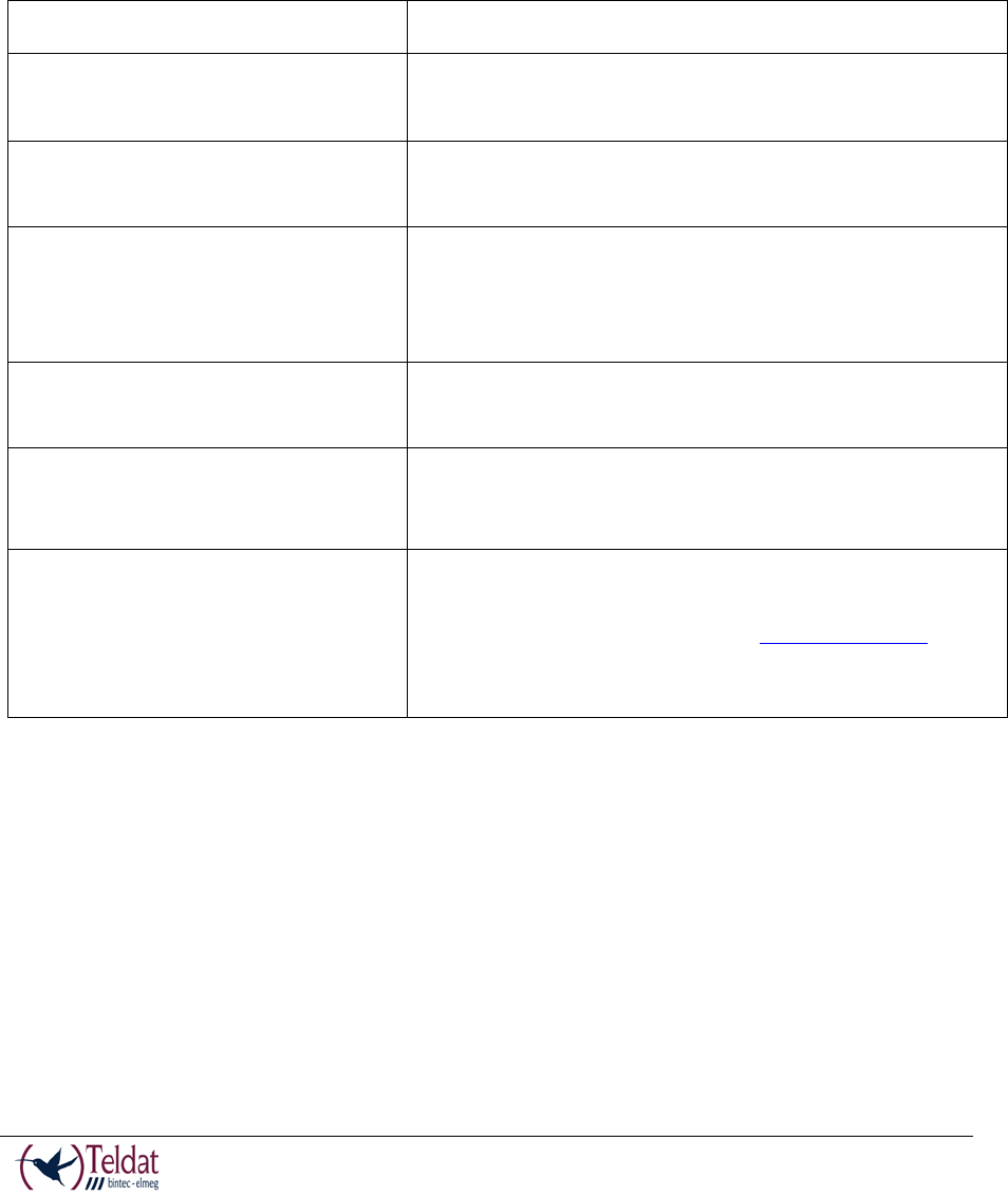
Troubleshooting
Below, you will find a table, which will help you to solve problems during the installation of the
router. If you cannot resolve the problem, please consult your distributor for additional
information.
Symptom
Solution
None of the LEDs lights up on the
router.
Check the power supply to the router (power source,
ON/OFF switch, main power outlet).
You have forgotten the access
password for the router.
Ignore the configuration through the RST button as
explained in the section relative to the RST button.
The DSL LED never lights up in
green.
If the device has an xDSL interface available, check the
connection to the network or to the splitter and make
sure that the telephone line you are connected supports
xDSL service.
The Eth WAN LED never lights up
in green.
Check the Ethernet cable and the connection to the
network.
The Wi-Fi LED never lights up in
green.
Check the router’s configuration and that for the remote
station(s).
Check the appropriate license is available for its use.
The USB LED never lights up in
green.
Check that the device inserted in the USB connector is
supported by the router.
Please check the Teldat website www.teldat.com to get
the list of 3G USB modems that are supported.
Check the appropriate license is available for its use.
Updating the software
The Teldat V router can be updated to new releases. Please consult your distributor for further
details on new releases.
There are various ways to update a Teldat router: For further information, please see the manual
on updating software: “Dm 748-I Software Updating”.
The software required to update Teldat routers is supplied in a format known as distribution.
This consists of a single file which contains all the files needed to update your device as well as
in-depth information on the contents of the files.
TELDAT V – Installation Manual
I - 26
Doc.DM567-I
Rev.4.0
The Teldat V incorporates independent modules for the Wireless WAN interface. You can use
modules from various manufacturers, or even various modules from the same manufacturer,
depending on the technology used. Generally the modules’ firmware is independent of the
device’s software. There is an UPGRADE file for each Wireless WAN module. Please ask you
distributor for the correct UPGRADE file for the module in your device. The document
describing the Cellular interface (manual Dm 781-I) explains how to UPGRADE the module.
Connectors
LAN Connector
RJ45 LAN
RJ45 PIN
FE Signals
GE Signals
1
2
3
4
5
6
7
8
BI-DA+
BI-DA-
BI-DB+
--
--
BI-DB-
--
--
BI-DA+
BI-DA-
BI-DB+
BI-DC+
BI-DC-
BI-DB-
BI-DD+
BI-DD-
TABLE 5. LAN CONNECTOR
WAN Connector
RJ45 WAN
RJ45 PIN
FE Signals
GE Signals
1
2
3
4
5
6
7
8
BI-DA+
BI-DA-
BI-DB+
--
--
BI-DB-
--
--
BI-DA+
BI-DA-
BI-DB+
BI-DC+
BI-DC-
BI-DB-
BI-DD+
BI-DD-
TABLE 6. WAN CONNECTOR
WWAN/Cell Connector (female)
PIN
ANT
Internal
External
RF in/out
GND
TABLE 7. WWAN/CELL CONNECTOR
TELDAT V – Installation Manual
I - 27
Doc.DM567-I
Rev.4.0
WLAN/WiFi Connector (male)
PIN
ANT
Internal
External
RF in/out
GND
TABLE 8. WLAN/WIFI CONNECTOR
DSL Connector
RJ11 DSL
RJ11 PIN
DSL
1
2
3
4
Joined to 2
Line
Line
Joined to 3
TABLE 9. DSL CONNECTOR
USB Connector
USB Type A
PIN
USB
1
2
3
4
Shell
VCC
DATA-
DATA+
GND
Shield
TABLE 10. USB CONNECTOR
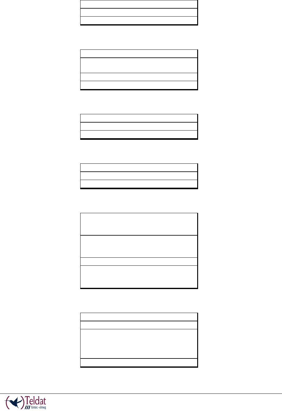
Configuration Connector
RJ45 CONFIGURATION
RJ45 PIN
CONF
1
2
3
4
5
6
7
8
--
RxD
GND
--
--
GND
TxD
--
TABLE 11. CONFIGURATION CONNECTOR
TELDAT V – Installation Manual
I - 28
Doc.DM567-I
Rev.4.0
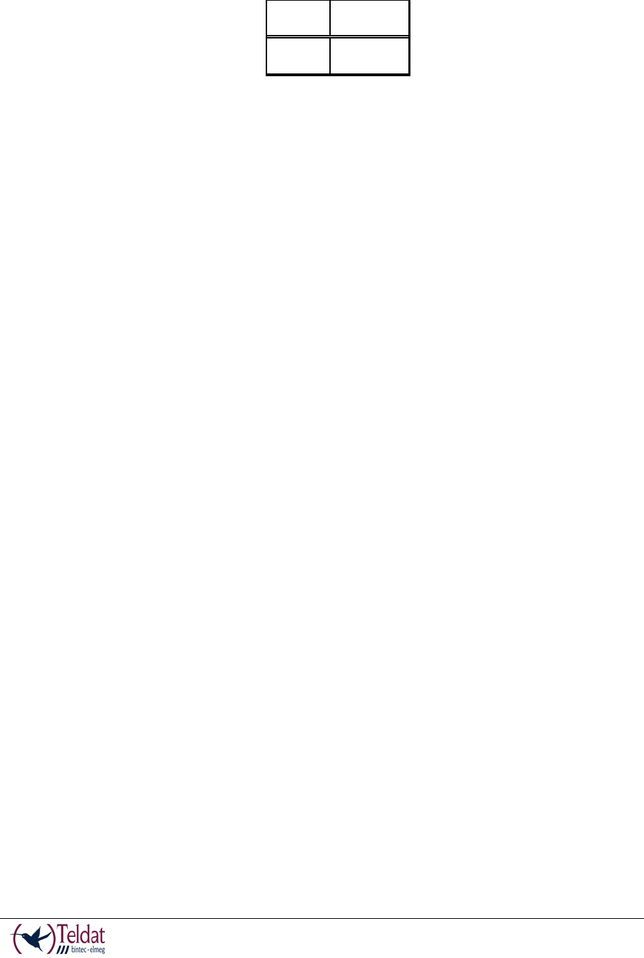
Power Supply Connector
PIN
ANT
Internal
External
POSITIVE
NEGATIVE
TABLE 12. POWER SUPPLY CONNECTOR
TELDAT V – Installation Manual
I - 29
Doc.DM567-I
Rev.4.0
Technical Specifications
Hardware Architecture
PROCESSORS
Broadcom BCM963168
MEMORY
128 Mbytes in SDRAM.
STORAGE UNIT
FLASH Memory (32 Mbytes).
LAN Interface
PROTOCOLS
Ethernet (802.3).
PORTS
4 port Switch managed with MDI/MDX
autodetection.
SPEED
10/100/1000 Mbps (BaseT).
CONNECTOR
RJ45 female.
WAN Interface
STANDARDS
Ethernet (802.3).
SPEED
10/100/1000 Mbps (BaseT)
CONNECTOR
RJ45 female.
DSL Interface
STANDARDS
Please see manual Dm 741-I
SPEED
Please see manual Dm 741-I
CONNECTOR
RJ11 female.
Wireless WAN Interface
STANDARDS
GPRS, UMTS, HSDPA, HSUPA, HSPA+, LTE …
Depending on the version of Wireless WAN
interface the router has incorporated.
SPEED
Depending on the version of Wireless WAN
interface the router has incorporated. Please
consult the module manual.
CONNECTOR
2 RF SMA Female per module.
ANTENNA
Depends on the type of Wireless WAN module.
Please consult the antenna catalog for Cellular
interfaces.
Wireless LAN Interface
STANDARDS
802.11abgn
FREQUENCY
2.4 GHz / 5 GHz
SPEEDs
Supports all mandatory data rates specified in
IEEE 802.11n up to 300 Mbps, and the legacy
rates specified in IEEE 802.11a/b/g including 1, 2,
5.5, 6, 9, 11, 12, 18, 24, 36, 48, and 54 Mbps
CONNECTOR
2 RF SMA Male
TELDAT V – Installation Manual
I - 30
Doc.DM567-I
Rev.4.0
USB Interface
3G USB MODEMS
Please see the Teldat website www.teldat.com to
get a list of the supported 3G USB modems.
SPEED
The interface complies with the USB 2.0 (480
Mbps) standard; the end speed depends on the
3G USB modem used.
CONNECTOR
USB Type A
Configuration Interface
LOCAL TERMINAL
V.24 9.600-8-N-1-without flow control.
CONNECTOR
RJ45 female on the device front panel.
Power Supply
INPUT VOLTAGE
+12V DC.
INPUT CURRENT
1200 mA
JACK
5,5 mm
INTERNAL PIN
2,5 mm
External Power Supply
INPUT VOLTAGE
100-240V AC
INPUT CURRENT
1.0 A
INPUT FREQUENCY
50-60 Hz
Dimensions and weight
TYPE
Desktop.
LENGTH x WIDTH x
HEIGHT
242 x 179 x 48 mm.
WEIGHT
0.8 Kg.
Environmental Specifications
TEMPERATURE
OPERATING NORMALLY: 0ºC to 45ºC
STORED: -30ºC to 85ºC
RELATIVE HUMIDITY
On: 5% to 90%

TELDAT V – Installation Manual
I - 31
Doc.DM567-I
Rev.4.0
Appendix C. Compliance
FCC Statement
Federal Communications Commission Interference Statement
This equipment has been tested and found to comply with the limits for a Class B digital device,
pursuant to Part 15 of the FCC Rules. These limits are designed to provide reasonable protection
against harmful interference in a residential installation. This equipment generates, uses and can
radiate radio frequency energy and, if not installed and used in accordance with the instructions,
may cause harmful interference to radio communications. However, there is no guarantee that
interference will not occur in a particular installation. If this equipment does cause harmful
interference to radio or television reception, which can be determined by turning the equipment
off and on, the user is encouraged to try to correct the interference by one of the following
measures:
• Reorient or relocate the receiving antenna.
• Increase the separation between the equipment and receiver.
• Connect the equipment into an outlet on a circuit different from that to which the receiver
is connected.
• Consult the dealer or an experienced radio/TV technician for help.
FCC Caution: Any changes or modifications not expressly approved by the party responsible
for compliance could void the user’s Authority to operate this equipment.
This device complies with Part 15 of the FCC Rules. Operation is subject to the following two
conditions: (1) This device may not cause harmful interference, and (2) this device must accept
any interference received, including interference that may cause undesired operation.
For product available in the USA/Canada market, only channel 1~11 can be operated. Selection
of other channels is not possible.
This device and it's antennas(s) must not be co-located or operating in conjunction with any other
antenna or transmitter except in accordance with FCC multi-transmitter product procedures.
This device is going to be operated in 5.15~5.25GHz frequency range, it is restricted in indoor
environment only.

TELDAT V – Installation Manual
I - 32
Doc.DM567-I
Rev.4.0
IMPORTANT NOTE:
FCC Radiation Exposure Statement:
This equipment complies with FCC radiation exposure limits set forth for an uncontrolled
environment. This equipment should be installed and operated with minimum distance 20cm
between the radiator & your body.
FCC 68
Customer Information
This equipment complies with Part 68 of the FCC rules and the requirements adopted by the
ACTA. On bottom of this equipment is a label that contains, among other information, a product
identifier of [US: TLDDL01BTLDPV00A1]. If requested, this number must be provided to the
telephone company.
If this equipment [Enterprise Router] causes harm to the telephone network, the telephone
company will notify you in advance that temporary discontinuance of service may be required.
But if advance notice isn't practical, the telephone company will notify the customer as soon as
possible. Also, you will be advised of your right to file a complaint with the FCC if you believe
it is necessary.
The telephone company may make changes in its facilities, equipment, operations or procedures
that could affect the operation of the equipment. If this happens the telephone company will
provide advance notice in order for you to make necessary modifications to maintain
uninterrupted service.
If you experience trouble with this equipment, you disconnect it from the network until the
problem has been corrected or until you are sure that the equipment is not malfunctioning.
Please follow instructions for repairing if any (e.g. battery replacement section); otherwise do not
alternate or repair any parts of device except specified.
If the telephone company requests information on what equipment is connected to their lines,
inform them of:
(a) The telephone number that this unit is connected to,
(b) The ringer equivalence number [01]
(c) The USOC jack required [RJ11C], and
(d) The FCC Registration Number [TLD]
Items (b) and (d) are indicated on the label. The ringer equivalence number (REN) is used to
determine how many devices can be connected to your telephone line. In most areas, the sum of

TELDAT V – Installation Manual
I - 33
Doc.DM567-I
Rev.4.0
the RENs of all devices on any one line should not exceed five (5.0). If too many devices are
attached, they may not ring properly.
Service Requirements
In the event of equipment malfunction, all repairs should be performed by our Company or an
authorized agent. It is the responsibility of users requiring service to report the need for service
to our Company or to one of our authorized agents. Service can be facilitated through our office
at:
Company Name: Teldat Corp
Contact Name: Ignacio Loizaga
Address: 15466 Los Gatos Blvd
Suite #109-335
Los Gatos CA 95032
Telephone No: 408 892 9363
Fax No: 408-608-2172
Email: iloizaga@teldat.com
IC Statement
CAN ICES-3 (B)/NMB-3(B)
This device complies with Industry Canada license-exempt RSS standard(s). Operation is subject
to the following two conditions: (1) this device may not cause interference, and (2) this device
must accept any interference, including interference that may cause undesired operation of the
device.
Le présent appareil est conforme aux CNR d'Industrie Canada applicables aux appareils radio
exempts de licence. L'exploitation est autorisée aux deux conditions suivantes : (1) l'appareil ne
doit pas produire de brouillage, et (2) l'utilisateur de l'appareil doit accepter tout brouillage
radioélectrique subi, même si le brouillage est susceptible d'en compromettre le fonctionnement.
For product available in the USA/Canada market, only channel 1~11 can be operated. Selection
of other channels is not possible.
Pour les produits disponibles aux États-Unis / Canada du marché, seul le canal 1 à 11 peuvent
être exploités. Sélection d'autres canaux n'est pas possible.
This device and it's antennas(s) must not be co-located or operating in conjunction with any other
antenna or transmitter except in accordance with IC multi-transmitter product procedures.

TELDAT V – Installation Manual
I - 34
Doc.DM567-I
Rev.4.0
Cet appareil et son antenne (s) ne doit pas être co-localisés ou fonctionnement en association
avec une autre antenne ou transmetteur.
The device could automatically discontinue transmission in case of absence of information to
transmit, or operational failure. Note that this is not intended to prohibit transmission of control
or signaling information or the use of repetitive codes where required by the technology.
Le dispositif pourrait automatiquement cesser d'émettre en cas d'absence d'informations à
transmettre, ou une défaillance opérationnelle. Notez que ce n'est pas l'intention d'interdire la
transmission des informations de contrôle ou de signalisation ou l'utilisation de codes répétitifs
lorsque requis par la technologie.
The device for the band 5150-5250 MHz is only for indoor usage to reduce potential for harmful
interference to co-channel mobile satellite systems.
Les dispositifs fonctionnant dans la bande 5150-5250 MHz sont réservés uniquement pour une
utilisation à l’intérieur afin de réduire les risques de brouillage préjudiciable aux systèmes de
satellites mobiles utilisant les mêmes canaux.
IMPORTANT NOTE:
IC Radiation Exposure Statement:
This equipment complies with IC RSS-102 radiation exposure limits set forth for an uncontrolled
environment. This equipment should be installed and operated with minimum distance 20cm
between the radiator & your body.
Déclaration d’exposition aux radiations au Canada:
Cet équipement est conforme aux limites d'exposition aux rayonnements IC établies pour un
environnement non contrôlé.
Cet équipement doit être installé et utilisé avec un minimum de 20 cm de distance entre la source
de rayonnement et votre corps.
TELDAT V – Installation Manual
I - 35
Doc.DM567-I
Rev.4.0
NOTE
For Industry Canada only:
Under Industry Canada regulations, this radio transmitter may only operate using an antenna of a
type and maximum (or lesser) gain approved for the transmitter by Industry Canada.
To reduce potential radio interference to other users, the antenna type and its gain should be so
chosen that the equivalent isotropically radiated power (e.i.r.p.) is not more than that necessary
for successful communication.
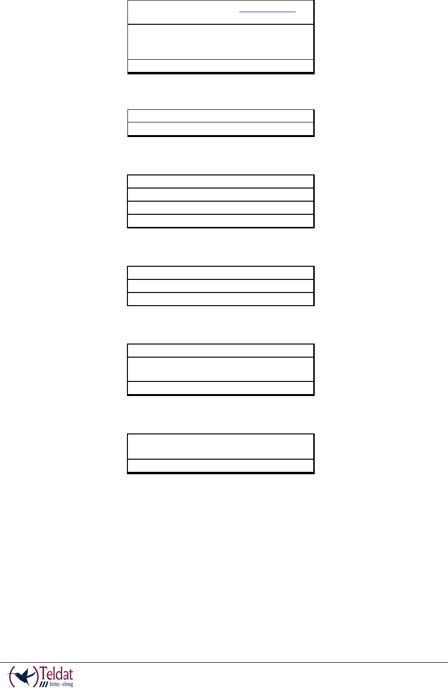
This radio transmitter (IC: 11046A-TLDPV00A1) has been approved by Industry Canada to
operate with the antenna types listed below with the maximum permissible gain and required
antenna impedance for each antenna type indicated.
Antenna types not included in this list, having a gain greater than the maximum gain indicated
for that type, are strictly prohibited for use with this device:
Model
Impedance
Gain
Power
EDA-8709-25GR2-A9
50 Ohm Nominal
2dBi (Typ.)
1W
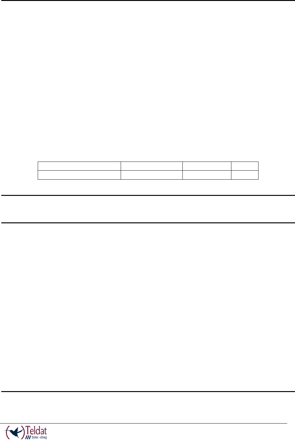
IC Telecom Statement:
This product meets the applicable Industry Canada technical specifications. /
Le présent matériel est conforme aux specifications techniques applicables d’Industrie Canada.
The Ringer Equivalence Number (REN) is an indication of the maximum number of devices
allowed to be connected to a telephone interface. The termination of an interface may consist of
any combination of devices subject only to the requirement that the sum of the RENs of all the
devices not exceed five.
L’indice d’équivalence de la sonnerie (IES) sert à indiquer le nombre maximal de terminaux qui
peuvent être raccordés à une interface téléphonique. La terminaison d’une interface peut
consister en une combinaison quelconque de dispositifs, à la seule condition que la somme
d’indices d’équivalence de la sonnerie de tous les dispositifs n’excède pas cinq.