Tele Radio C1101A Receiver User Manual IM TGS RX001 A10 EN on March 15 2011
Tele Radio AB Receiver IM TGS RX001 A10 EN on March 15 2011
User manual
1
Manual
and installation instructions
Technology by:

TigerShark
boat lift solutions
2
Table of contents
Getting started ..................................................................... 3
Control panel ...................................................................................................................... 4
Raise/lower the boat using automatic systems ...................................................................4
Raising/lowering the boat manually ........................................................................................5
Adjusting the boat hoist level ...................................................................................................6
Raising/lowering the boat outside of the boat hoist’s stopping positions. ..................7
Remote control .................................................................................................................. 8
Raising/lowering the boat using remote control ................................................................8
Other remote control functions: ......................................................................................... 10
Installation ........................................................................... 11
Limit switch .................................................................................................................................12
Functional description of limit switch ..................................................................................13
Adjustment of limit switch (hoist) ........................................................................................14
Adjusting the limit switch (lowering) ...................................................................................15
Connection of limit switch to radio receiver ....................................................................16
Installation ........................................................................... 17
Mounting the limit switch into the hoist motor............................................................... 18
SAFETY II stop function.......................................................................................................... 23
General notice ..................................................................... 24
Installation ........................................................................... 25
Connecting hoist motors to the control panel ................................................................ 26
Standard color coded motor .......................................................................................................... 26
Standard T-motor .............................................................................................................................28
Eastbay motor ...................................................................................................................................30
AO Smith motor ................................................................................................................................ 32
Leeson Balldor motor.......................................................................................................................34
General Electric motor ....................................................................................................................36
Century Magnatech motor ............................................................................................................ 38
Emerson motor .................................................................................................................................. 40
Leeson motor...................................................................................................................................... 42
Baldor motor ......................................................................................................................................44
Appendix 2-motor lifts ....................................................... 46
Connection schematics ........................................................................................................... 47
Wire size recommendation chart ........................................................................................ 54
Pairing a transmitter to the TigerShark ............................................................................. 56
Deleting transmitters for the TigerShark .......................................................................... 57
Appendix 4-motor lifts ....................................................... 58
Connection schematics ........................................................................................................... 59

3
Getting started
How to use the control panel and the remote control for the boat hoist
WARNING any adjustment to TigerShark not described in this manual or
approved in writing by TeleRadio voids warranty and releases TeleRadio and its
subsidiaries from liability due to improper handling or installation.
All manouvering of the lift has to be monitored by the user.
AUTO stop function is a convenience function, lift still has to be monitored by
the user.
SAFETY function is in place to minimize damage in the event of lift failure, lift
still has to be monitored by the user.
WARNING when lift is not in use the power should be disconnected either at
the mains power switch or at the ground fault interruptor switch in the control
panel housing.
WARNING the control panel housing should always be locked or screwed shut
to avoid use by unauthorized party(ies).
WARNING the lift should only be operated by users who have read and
understood the instructions.
WARNING do not climb or play on the lift as there is risk for personal injury.
WARNING electrical installation can only be performed by licensed electricians.
The radio control system should only be used for functions such as starting
and halting of an application. The radio control systems must not be a safety-
related part of a control system. We recommend a wired emergency stop where
applicable, as well as other protections against personal injuries, e.g. pinch
protection.
TigerShark
boat lift solutions
4
AUTO ON
AUTORUN
OVERIDE
OFF
BOAT DOWN
BOAT UP
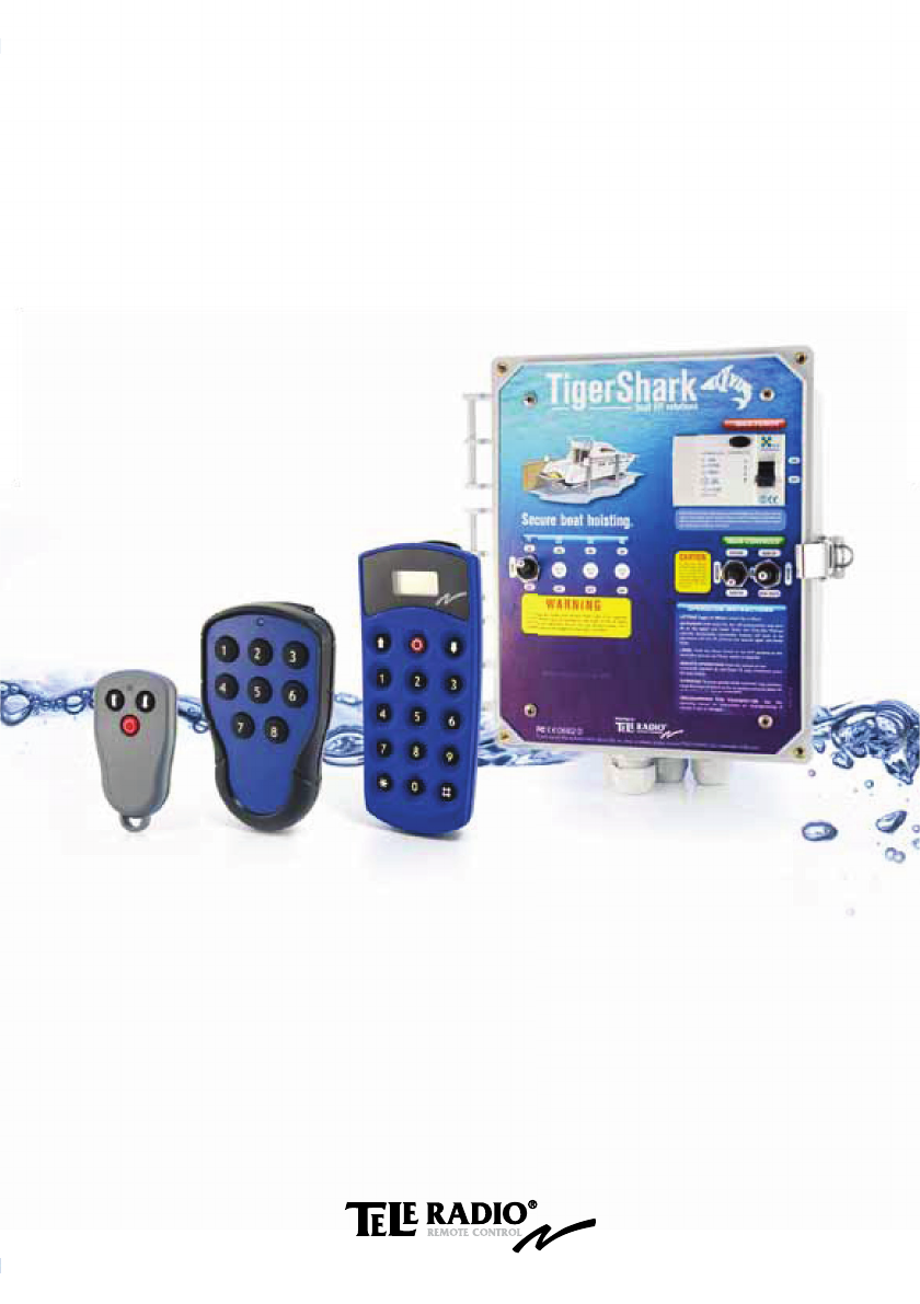
Raise/lower the boat using automatic systems
You can use the automatic systems to raise or lower the boat to a preset position
by briefly pressing the boat up/down lever. The boat can be raised or lowered to
the position set as the end point during installation. See page 12.
Raising the boat automatically:
AUTO ON
AUTORUN
OVERIDE
OFF
BOAT DOWN
BOAT UP
Lowering the boat automatically:
Control panel
Explanation of signs:
= Quick press = Hold down/up
5
AUTO ON
AUTORUN
OVERIDE
OFF
BOAT DOWN
BOAT UP
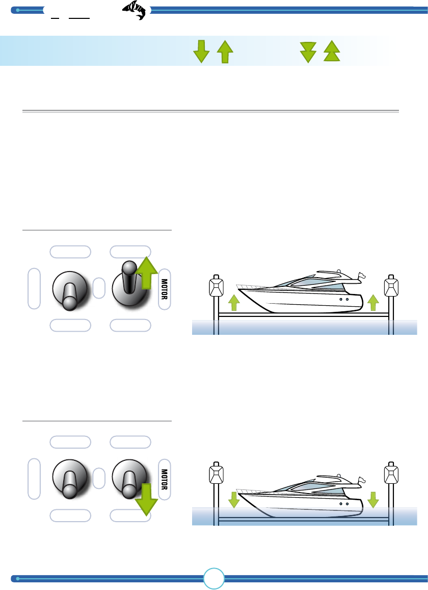
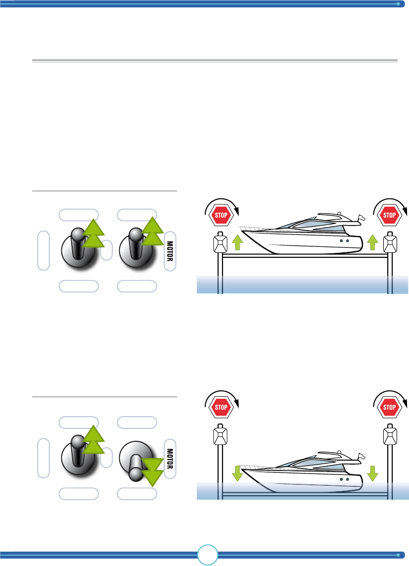
Raising/lowering the boat manually
You can lower or raise the boat manually without using the automated stopping sys-
tem. When the boat has been raised or lowered to its final position, the hoist turns
off. The boat is only raised or lowered as long as the lever is held up or down.
The boat can be lowered or raised to the position set as the end position.
See page 12.
Raising the boat manually:
AUTO ON
AUTORUN
OVERIDE
OFF
BOAT DOWN
BOAT UP
Lowering the boat manually:
TigerShark
boat lift solutions
6
AUTO ON
AUTORUN
OVERIDE
OFF
BOAT DOWN
BOAT UP
AUTO ON
AUTORUN
OVERIDE
OFF
BOAT DOWN
BOAT UP
Adjusting the boat hoist level
You can adjust the level of the hoist motors using the control panel. Do this by
turning off one of the motors using the LEVEL breaker. This may be necessary if
the boat hoist is on a slant or if a level adjustment must be performed for other
reasons.
Adjusting the level of the hoist upward:
Adjusting the level of the hoist downward:
OFF
ON
LEVEL
OFF
ON
LEVEL
Note! The motor used for level adjustment varies depending on
the boat hoist. Check with your installer before use.
Note! The motor used for level adjustment varies depending on
the boat hoist. Check with your installer before use.
WARNING! Be careful when adjusting the level, as too high an adjustment can
endanger the boat hoist’s load.
7
AUTO ON
AUTORUN
OVERIDE
OFF
BOAT DOWN
BOAT UP
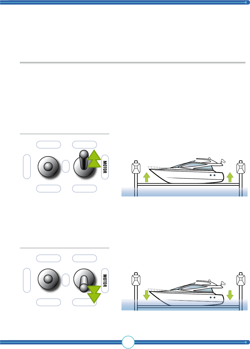
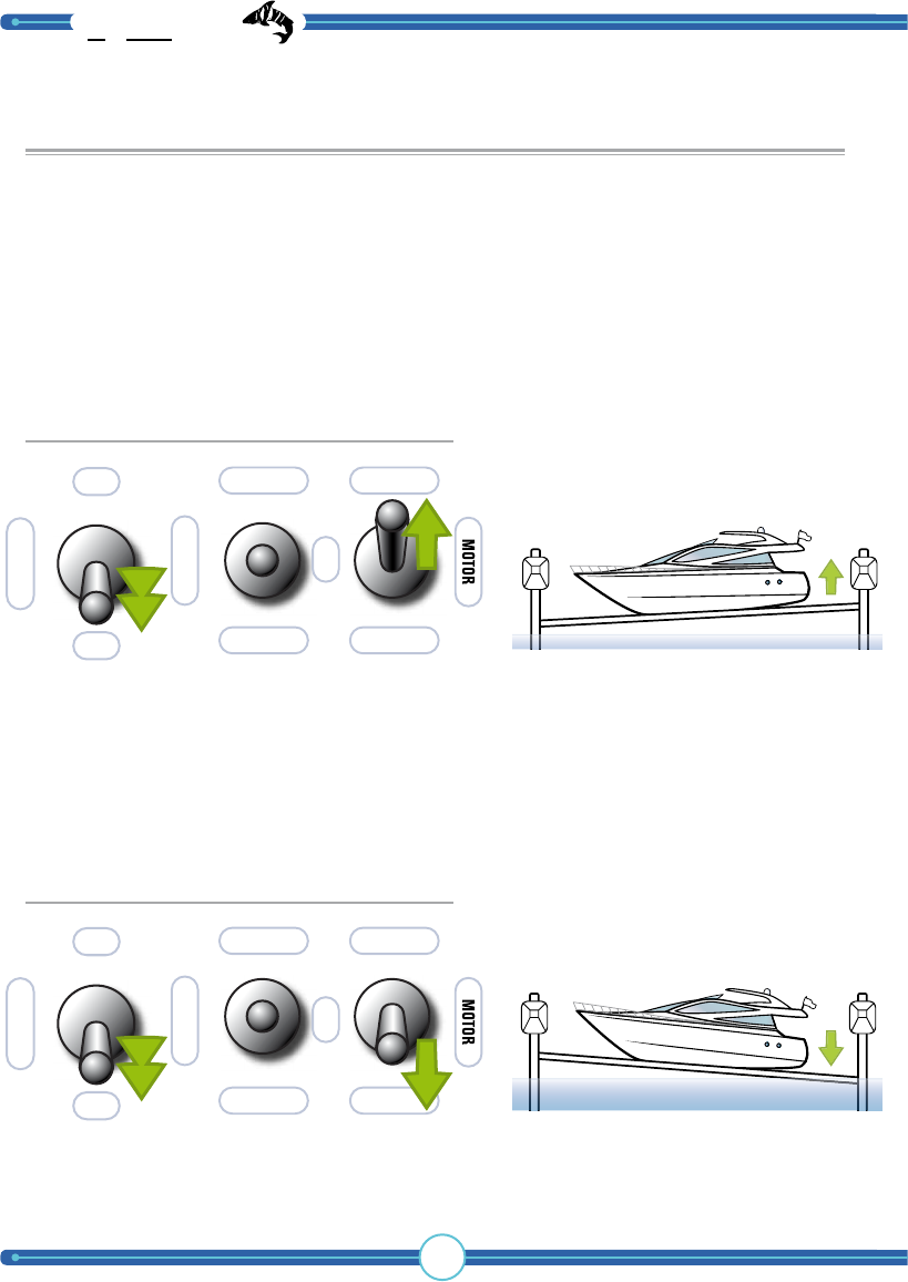
Raising/lowering the boat outside of the boat hoist’s
stopping positions.
You can lower or raise the boat outside of the preset stopping positions for the
boat hoist. This can be useful (i.e. at high or low tide), when the hoist doesn’t
reach high or low enough. Hold the lever toward the STOP POSITION to get
past the automatic stop.
Raising outside of stop positions:
AUTO ON
AUTORUN
OVERIDE
OFF
BOAT DOWN
BOAT UP
Lowering outside of stop positions:
WARNING! Raising/lowering the boat outside of the preset end positions can lead
to serious equipment damage if proper care is not exercised. For this reason, be very
careful when using this function.
TigerShark
boat lift solutions
8
Remote control
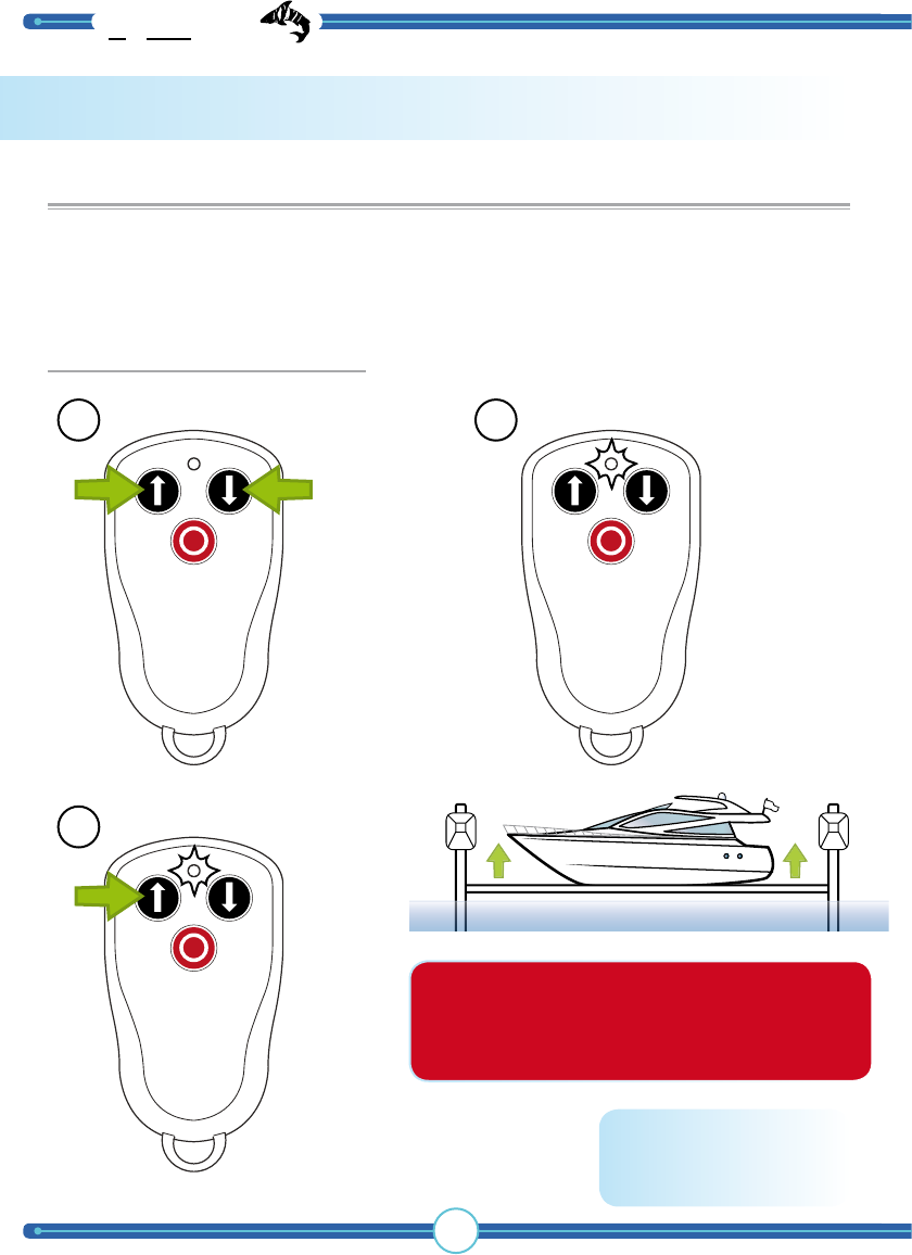
Raising/lowering the boat using remote control
You can automatically* lower or raise the boat to a preset position by briefly
pressing either the up or down button. The boat is lowered or raised to the
position set as the end point during installation.
1 2
2
Press both arrow
buttons to turn
transmitter power on.
Transmitter times out after 2 minutes of
inactivity. To re-activate, repeat step 1.
Note: Transmitter is already paired with
the receiver.
*) If your lift is not equipped with a limit switch, you do
not have the automatic lift/lower functionality. You must then
continuously hold the up/down button. Be aware that the lift
can then be raised/lowered outside its maximum limits with
possible equipment damage or personal injury as a result.
The LED turns
on.
Pressing the up button will
raise the boat hoist to the
stop position.
Raising the boat automatically*:
9
1 2
2
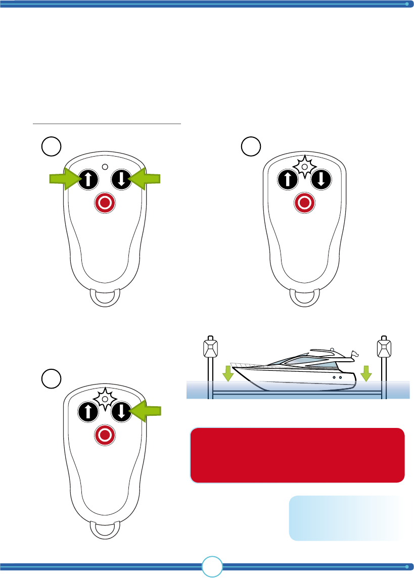
*) If your lift is not equipped with a limit switch, you do
not have the automatic lift/lower functionality. You must then
continuously hold the up/down button. Be aware that the lift
can then be raised/lowered outside its maximum limits with
possible equipment damage or personal injury as a result.
Transmitter times out after 2 minutes of
inactivity. To re-activate, repeat step 1.
Note: Transmitter is already paired with
the receiver.
Lowering the boat automatically*:
Press both arrow
buttons to turn
transmitter power on.
The LED turns
on.
Pressing the down button
lowers the boat hoist to the
stop position.
TigerShark
boat lift solutions
10
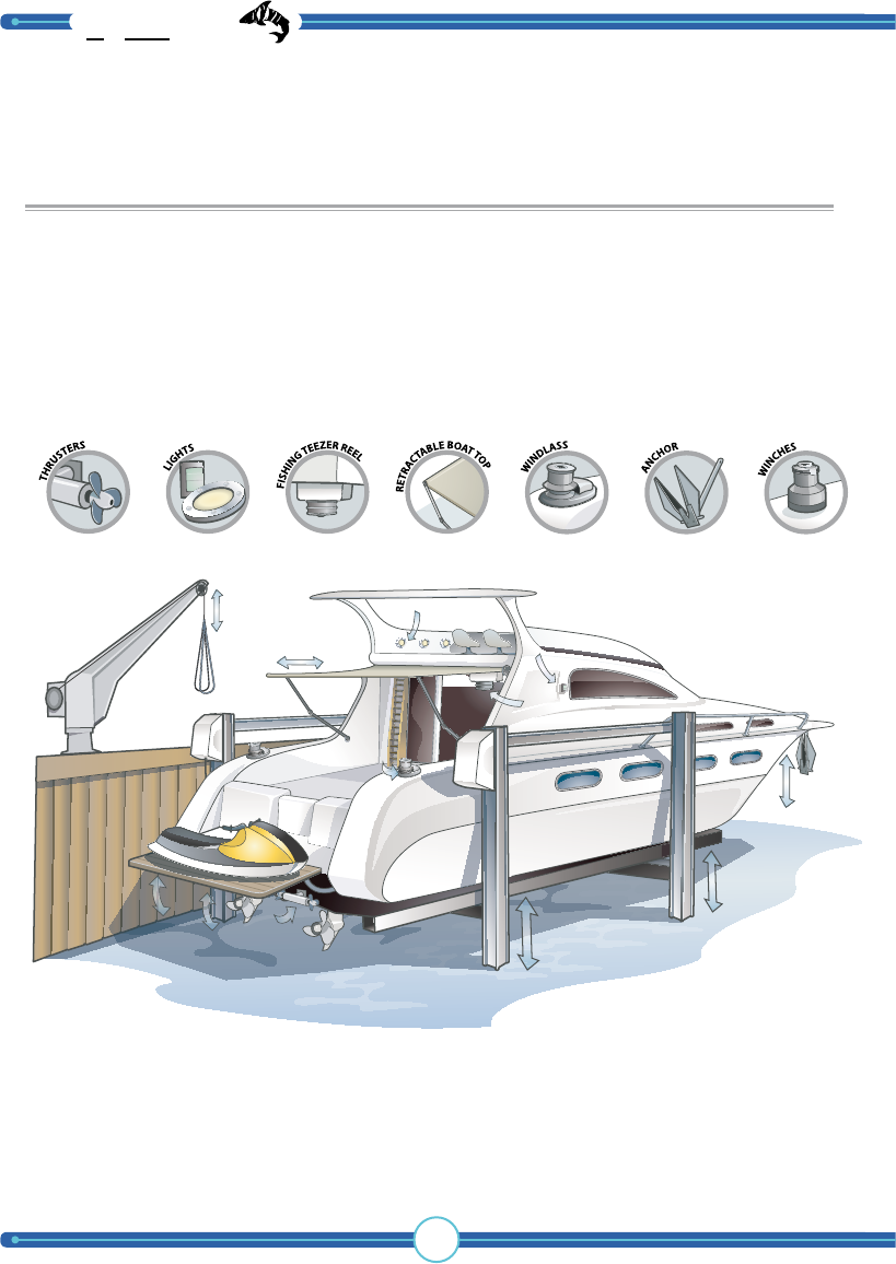
Other remote control functions:
The remote control can also be used to control other objects on or around the
boat. The standard remote control supports the control of two different objects.
You will find suggestions below. Your re seller can provide you with a transmitter
that allows you to control several objects at once.
Contact your re seller for more information. Please note that extra equipment
may be required.
Other objects may include jet ski hoists, harbour cranes, boat cranes,
ramps or boat traverses.
11
Installation
How to install
WARNING! This section of the
manual is only for licensed electricians and
installers. Interference with high-voltage
equipment is illegal for individuals without
the required training/authorization.
WARNING
Hazardrous voltage
Contact may cause
electric shock or burn.
Disconnect power
before servicing.
WARNING
Hazardrous voltage
Wrongful handling may cause
electric shock or burn.
Can only be installed
by licensed electrician.
the control panel
TigerShark
boat lift solutions
12
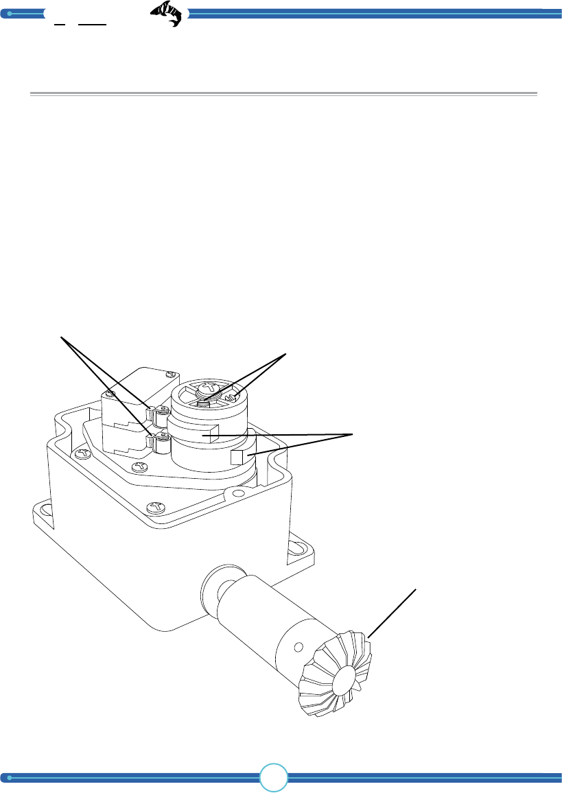
Limit switch
The limit switch is connected to the boat hoist motor. With the help of a micro-
breaker, this unit senses how high or how low the boat hoist has been moved.
When the boat hoist is in the top position, a high position breaker cuts the power
to the motor.
When the boat hoist is in the bottom position, a low position breaker cuts the
power to the motor.
Adjustment screws
Micro-breakers
Breaker handle
Motor connection
13
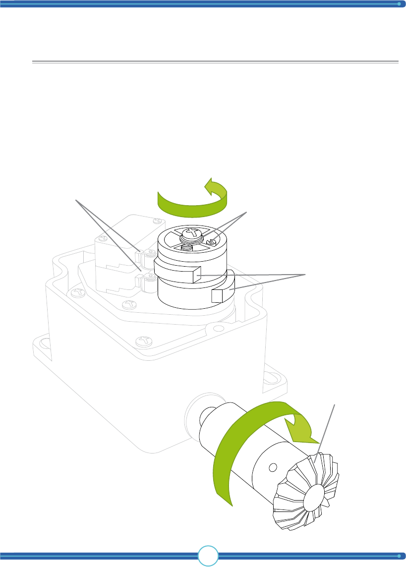
Functional description of limit switch
The limit switch, which connects to the engine axle, is turned when the engine
axle is spinning, turning the breaker handle in turn. The breaker handle should be
adjusted so that when the engine axle is spinning enough, (i.e. when the hoist is in
the desired top or bottom position), the micro-breakers engage to cut the power
to the motor.
Adjustment screws
Micro-breakers
Breaker handle
Motor connection
WARNING! Be careful to check which breaker handle is for the top position and
which is for the bottom position. This depends on how the limit switch is installed.
TigerShark
boat lift solutions
14
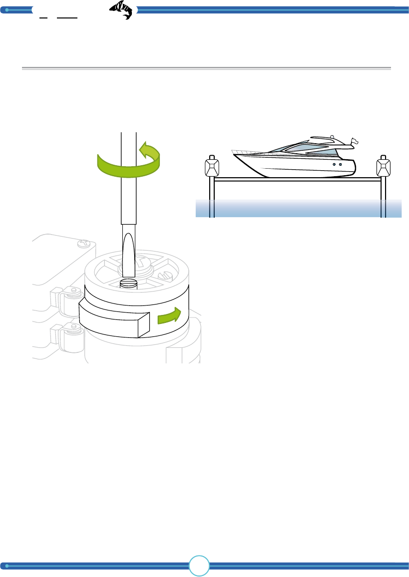
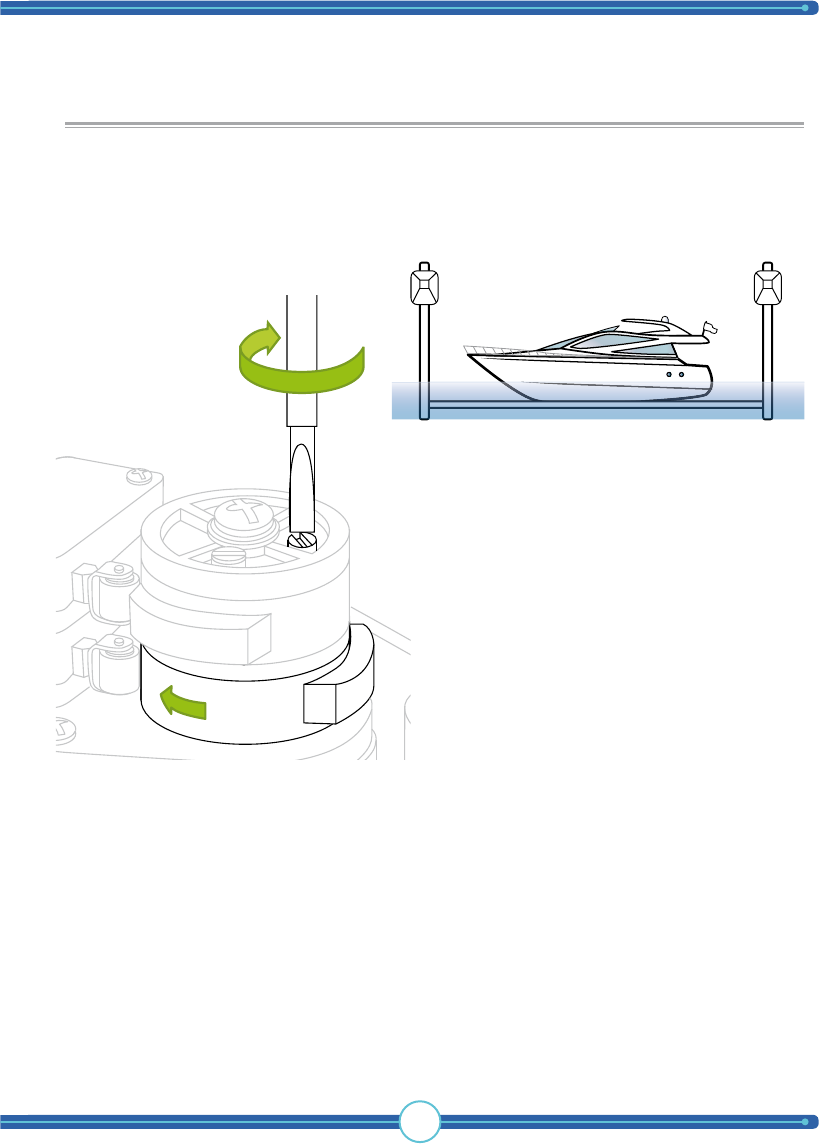
Adjustment of limit switch (hoist)
In order for the limit switch to work properly, it needs to be adjusted upon
installation. This is done in two steps, first when the boat hoist is in the top
position, and then when it is in the bottom position - this is when the breaker
handles are adjusted.
When the hoist is in the desired top position, turn the screw that corresponds to
the handle/breaker you selected to regulate the height. Turn the screw until the
breaker handle activates the micro-breaker with a click.
When the breaker handle reaches this position during a hoist, the micro-breaker
will cut power to the relay that controls the hoist function.
Adjust the boat hoist or the hoisting motors to the position that corresponds to
the hoist’s top position. That is, the highest position you want to be controlled
by “AUTORUN.”
NOTE! In this example, the lower breaker has been chosen to control the lowering relay. This
may vary by installation. Depending on how the position indicator is attached, the meaning of
the breakers may be reversed. For this reason, take the necessary precautions during installa-
tion and testing to prevent damage to people or property.
NOTE! This function must be checked carefully to avoid incorrect boat hoist operation.
15
Adjusting the limit switch (lowering)
In order for the limit switch to work properly, it needs to be adjusted upon
installation. This is done in two steps, first when the boat hoist is in the top
position, and then when it is in the bottom position - this is when the breaker
handles are adjusted.
When the hoist is in the desired bottom position, turn the screw that corresponds
to the handle/breaker you selected to regulate the lowering function. Turn the
screw until the breaker handle activates the micro-breaker with a click.
When the breaker handle reaches this position during lowering, the micro-breaker
will cut the power to the relay that controls the lowering function.
Adjust the boat hoist or the hoisting engines to the position that corresponds
to the hoist’s bottom position. That is, to the lowest position you want to be
controlled by “AUTORUN.”
NOTE! In this example, the lower breaker has been chosen to control the lowering relay. This
may vary by installation. Depending on how the position indicator is attached, the meaning of
the breakers may be reversed. For this reason, take the necessary precautions during installa-
tion and testing to prevent damage to people or property.
NOTE! This function must be checked carefully to avoid incorrect boat hoist operation.
TigerShark
boat lift solutions
16
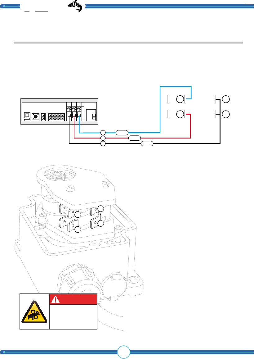
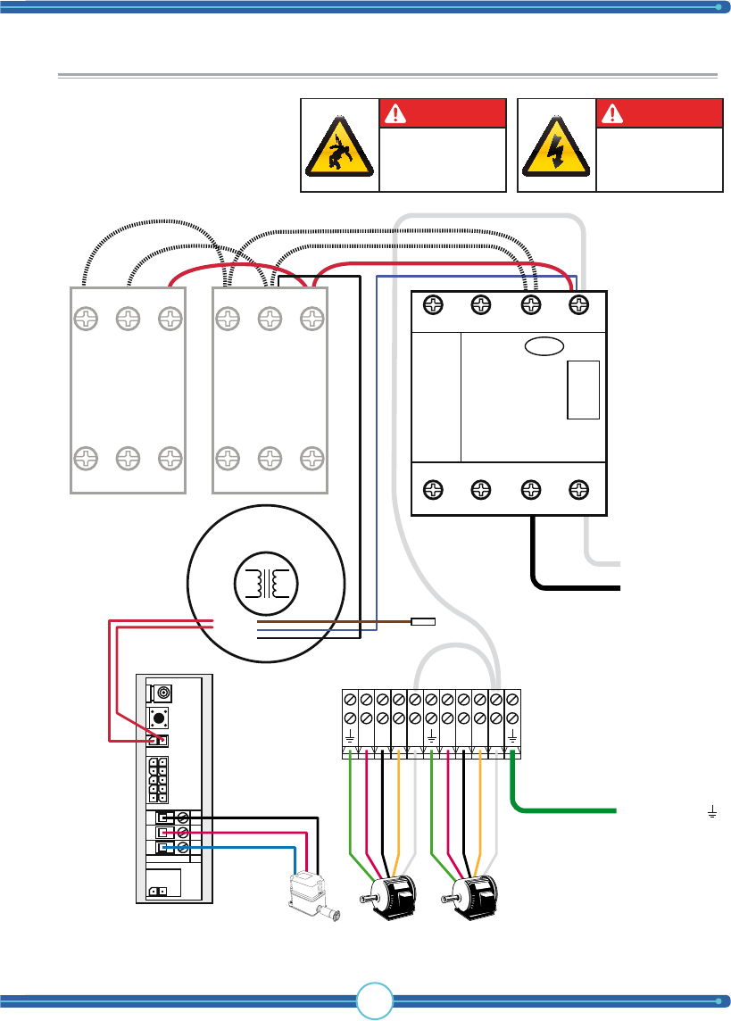
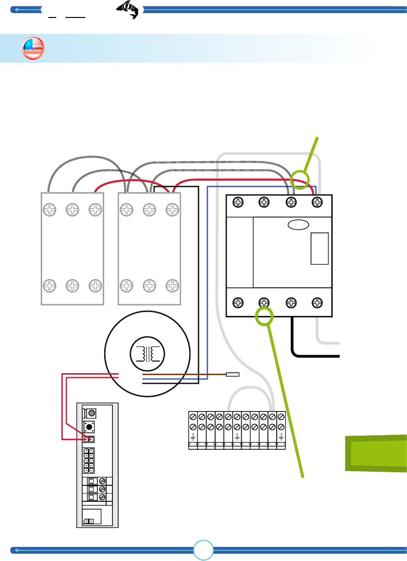
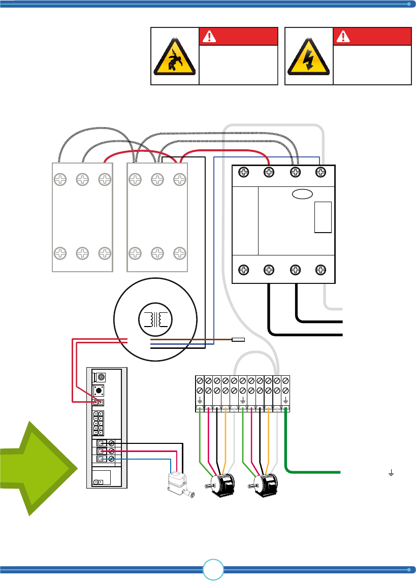
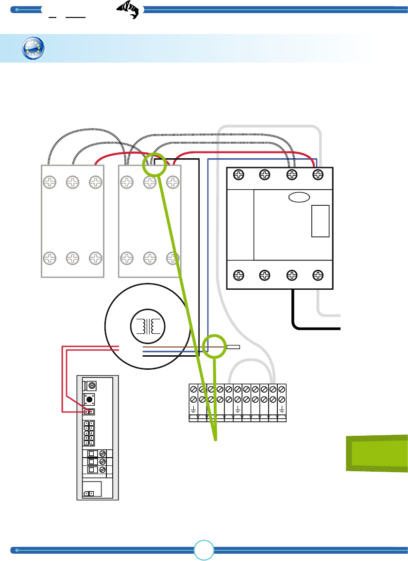
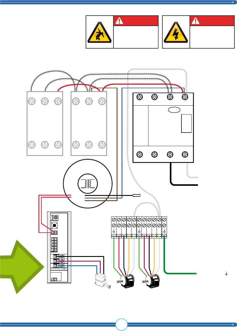
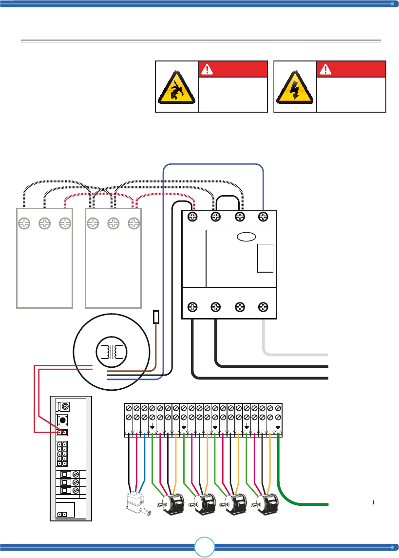
Connection of limit switch to radio receiver
Below, you’ll see how the connections should be drawn from the micro-breakers’
poles to the radio receiver in the control panel.
C
B
A
A
A
A
C
C
B
A
B
BLACK
RED
BLUE
WARNING! It is very important
that this phase of the installation is
carefully thought out and performed
with precision. If the micro- breakers
are connected incorrectly, thus disabling
them, the hoist will NOT stop at the au-
tomatic stop positions, leading to serious
equipment damage as a result. For this
reason, test the hoist equipment without
the automatic hoisting features before
installation. See “Raising/lowering the
boat outside of the boat hoist’s stopping
positions.” for information on how to do
this.
WARNING
Moving parts can crush.
Exposed mechanical
parts of boat lift equip.
Stay away from boat
lift when operating.
Connections between limit switch and recevier
TIP: If the boat hoist does not stop at
the end position, you can remedy this
by switching conductors (B) and (C) in
the receiver box. This will reverse the
breaker handles’ functionality.

17
Installation
How to install the
WARNING! This section of the
manual is only for licensed electricians and
installers. Interference with high-voltage
equipment is illegal for individuals without
the required training/authorization.
WARNING
Hazardrous voltage
Contact may cause
electric shock or burn.
Disconnect power
before servicing.
WARNING
Hazardrous voltage
Wrongful handling may cause
electric shock or burn.
Can only be installed
by licensed electrician.
limit switch & safety stop function
TigerShark
boat lift solutions
18
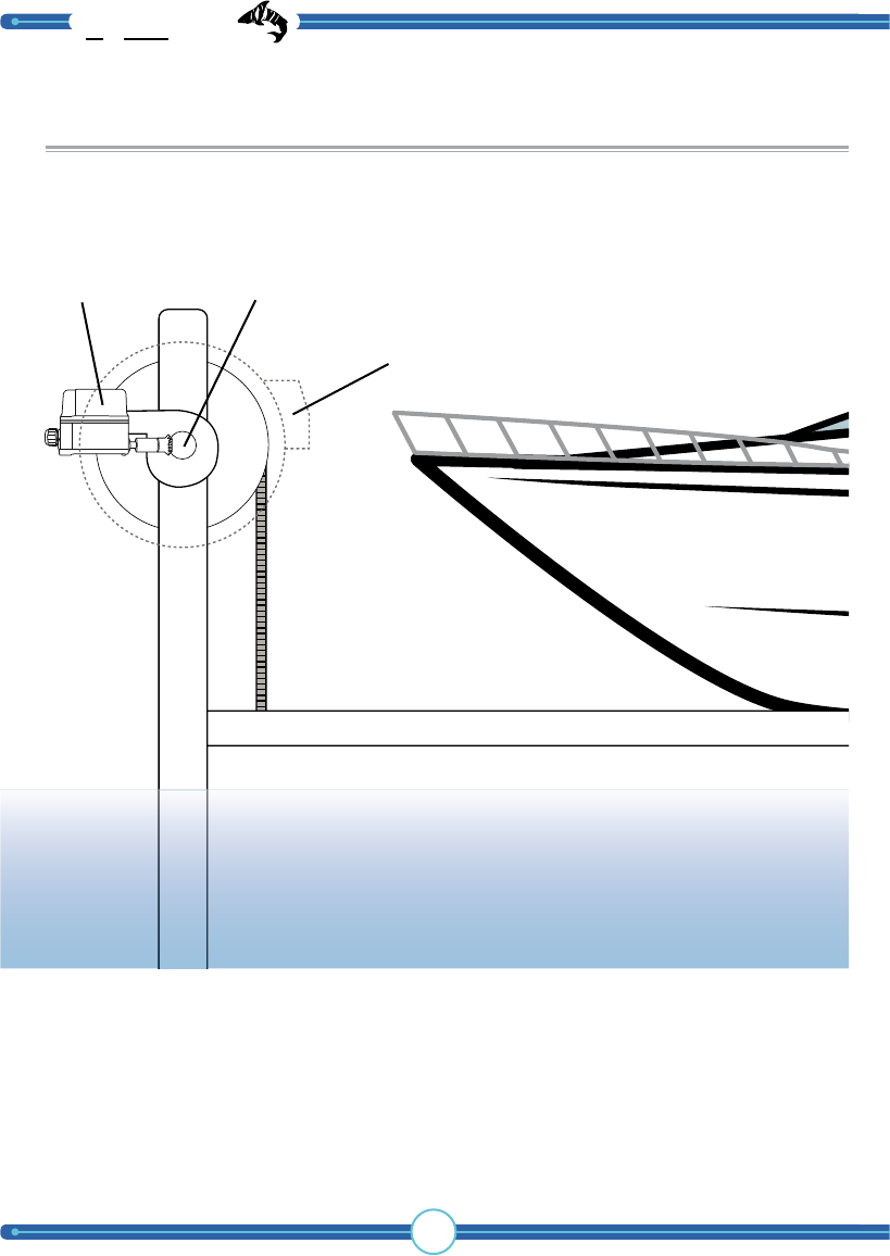
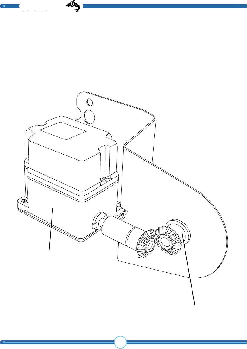
Mounting the limit switch into the hoist motor
The installation of the limit switch may vary depending on the type of boat hoist it
is being installed on. Below are some examples.
In the image, the limit switch is mounted at a 90 degree angle to the crankshaft.
The motor connection’s cogwheel on the limit switch is connected to a cogwheel
on the boat hoist’s crankshaft.
NOTE! This function must be checked carefully to avoid incorrect boat hoist operation.
Crankshaft
Hoist motor
Limit switch
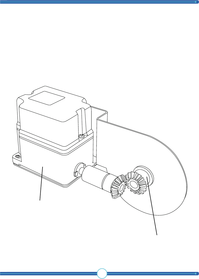
19
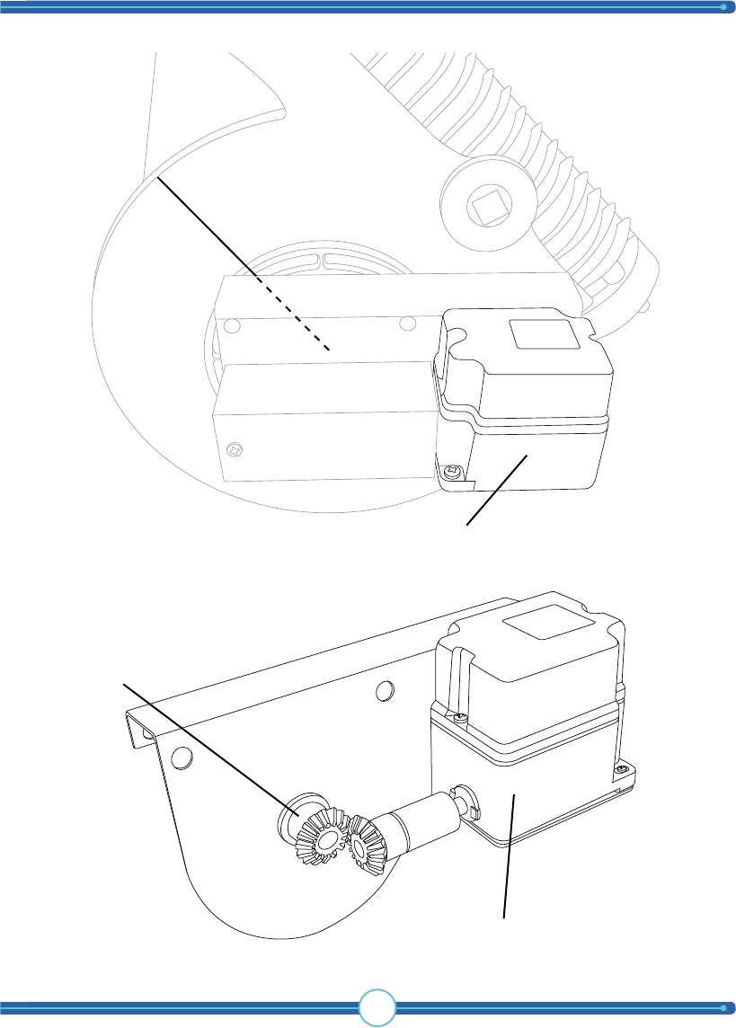
Crankshaft
Limit switch
Crankshaft
Limit switch
TigerShark
boat lift solutions
20
Crankshaft
Limit switch
Option 2
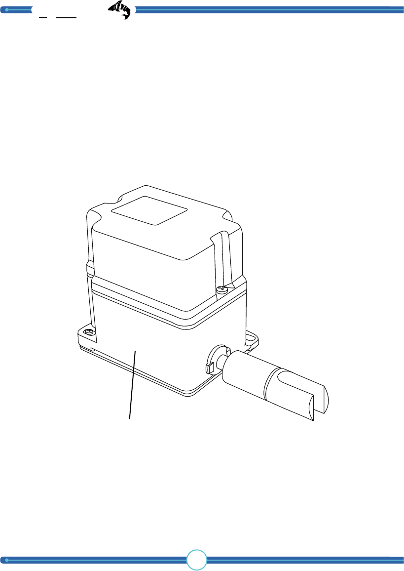
21
Option 3
Crankshaft
Limit switch
TigerShark
boat lift solutions
22
Option 4
Limit switch
23
SAFETY II stop function
The Tigershark 2.0 has many safety features as standard in order to prevent prob-
lems. In order to make the lift even more secure an added control feature can
be activated called SAFETY II. To activate this feature the lift has to be installed
completely and tested.
NOTICE! When using the SAFETY II function the lift should always be tested to
verify that the programming was successful.
1. Run a whole lift cycle, up and down, to verify that top- and bottom end posi-
tions are at a satisfactory level.
2. Lower the lift to the bottom end position, lift should stop automatically when
the limit switch perceives it has reached the bottom end position.
5. Lift goes up, when the lift reaches the pre-programmed top end position the lift
stops and the receiver stores the cycle time.
6. When the receiver stores the cycle time a yellow LED will blink in the receiver.
This can be hard to see so a manual test of the SAFETY II function is recommended.
1. Adjust the limit switch top position to a point where the lift stops higher up.
2. Lower the lift to the bottom end position.
3. Raise the lift, either manually or with the transmitter.
4. The lift should now stop before the limit switch engages.
5. Adjust the limit switch top position back to its original stop position.
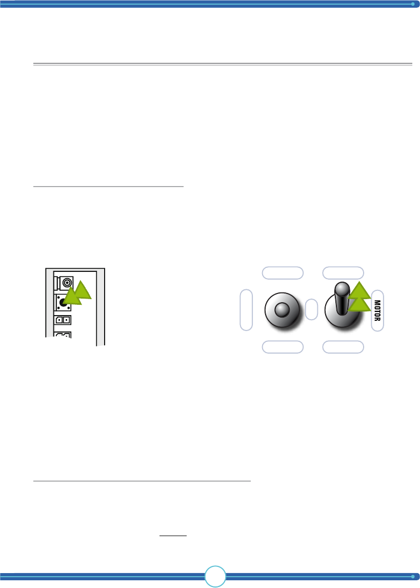
3. Press the indicated button on the
receiver. The RED led will light up.
4. Immediately move the indicated
control panel switch to “BOAT UP”.
~AUTO ON
AUTORUN
OVERIDE
OFF
BOAT DOWN
BOAT UP
Activating the SAFETY II function:
Manual testing of the SAFETY II function:

TigerShark
boat lift solutions
24
General notice
The TigerShark system is delivered in
a 120V (1 phase 120V) version.
The reason behind this is to minimize
the following if the wrong installation is
performed:
• Possible transformer blowout
• Possible contactor blowout
• Possible motor destruction and or fire

25
Installation
How to connect
WARNING! This section of the
manual is only for licensed electricians and
installers. Interference with high-voltage
equipment is illegal for individuals without
the required training/authorization.
WARNING
Hazardrous voltage
Contact may cause
electric shock or burn.
Disconnect power
before servicing.
WARNING
Hazardrous voltage
Wrongful handling may cause
electric shock or burn.
Can only be installed
by licensed electrician.
hoist motors to the control panel
WARNING: Motor connections shown
are to be used as a guide. We require
you to contact your boat lift dealer, motor
manufacturer, installer and professional
electrician to double check and verify
connections to your boat lift as many
motors change over time.
Tele Radio will not be responsible for
improper connections.
There are a number of different motor solutions on the market. We present the
most COMMON ones here.
NOTE: Your motor MAY NOT be pictured
Read the instructions for your motor for the correct connection. Tele Radio
cannot be held responsible for connections made OUTSIDE the TigerShark box.
TigerShark
boat lift solutions
26
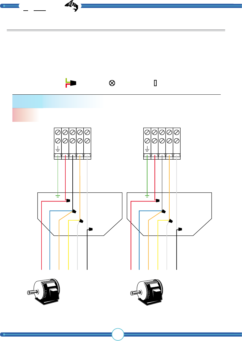
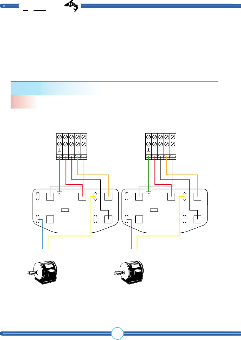
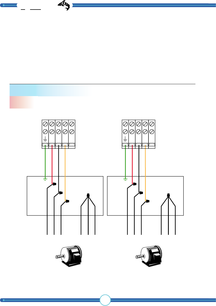
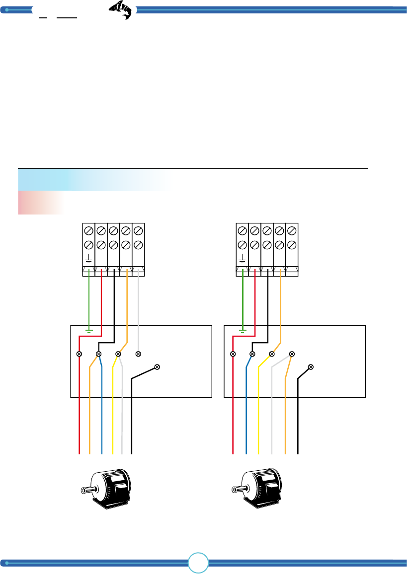
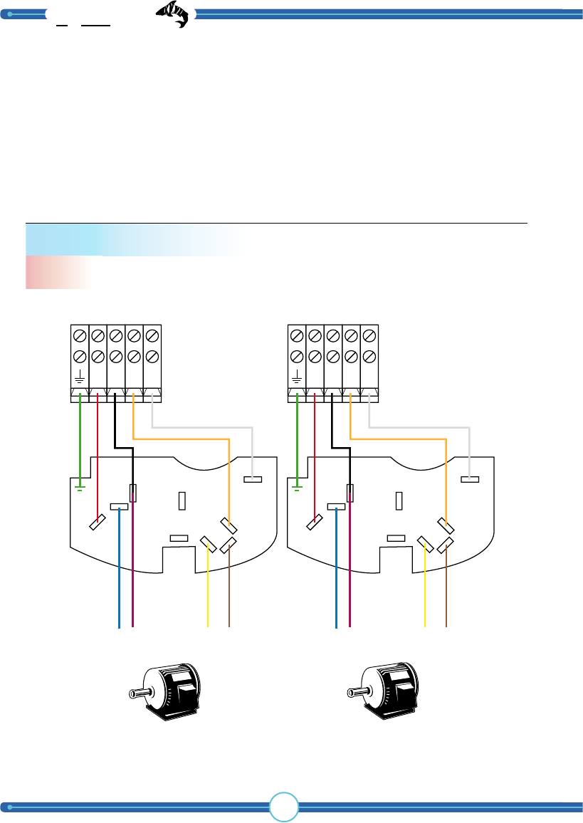
Standard color coded motor
120 V
A.O. Smith, Baldor, Dayton, Electrogear,
Emerson, Leeson, Lincon, Marathon and
other colored motor wires.
Motor 1 Motor 2
TIP: To change direction, switch MOTOR RED & BLACK.
NR1B1O1
GROUND
RED
BLACK
ORANGE
WHITE
Motor RED
Motor BLUE
Motor ORANGE
Motor YELLOW
Motor WHITE
Motor BLACK
Motor RED
Motor BLUE
Motor ORANGE
Motor YELLOW
Motor WHITE
Motor BLACK
A
B
C
D
NR2B2O2
GROUND
RED
BLACK
ORANGE
WHITE
A
B
C
D
Connecting hoist motors to the control panel
= Cap = Screw = Pin
Wiring symbols
WARNING: Motor connections shown are to be used as a guide. We require you to
contact your boat lift dealer, motor manufacturer, installer and professional electrician to
double check and verify connections to your boat lift as many motors change over time.
Tele Radio will not be responsible for improper connections.
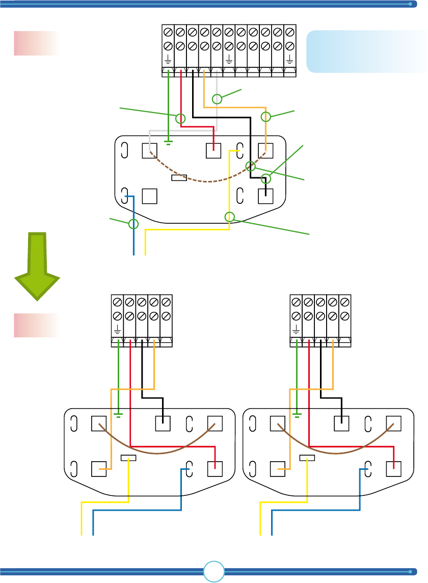
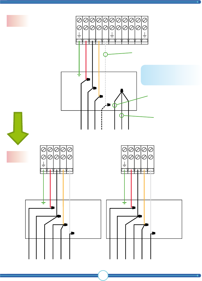
27
NR1B1O1
GROUND
RED
BLACK
ORANGE
WHITE
Motor RED
Motor BLUE
Motor ORANGE
Motor YELLOW
Motor WHITE
Motor BLACK
A
B
C
D
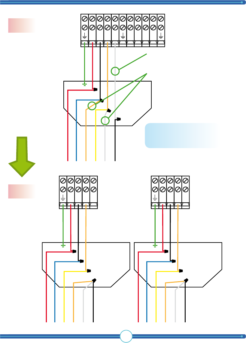
NR1B1O1
R2B2O2N
GROUND
Motor RED
Motor BLUE
Motor YELLOW
Motor ORANGE
Motor WHITE
Motor BLACK
RED
BLACK
ORANGE
A
B
C
D
NR2B2O2
GROUND
Motor RED
Motor BLUE
Motor YELLOW
Motor ORANGE
Motor WHITE
Motor BLACK
RED
BLACK
ORANGE
A
B
C
D
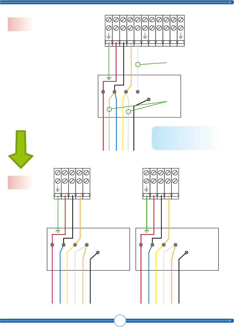
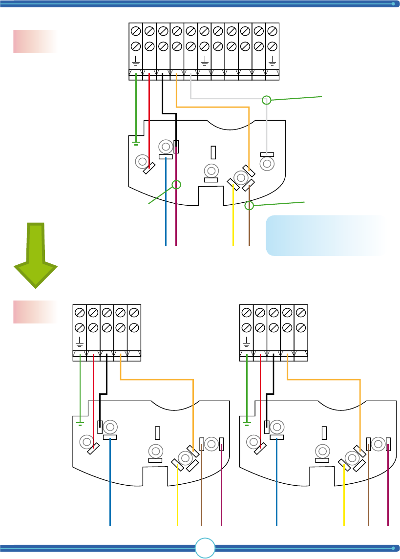
Wire together Motor ORANGE with
Motor WHITE & BLACK at position
marked “D”.
Remove TigerShark White.
Changeover process
120 V
230 V
From 120 V to 230 V
NOTE: Do this change on
both motors!
TigerShark
boat lift solutions
28
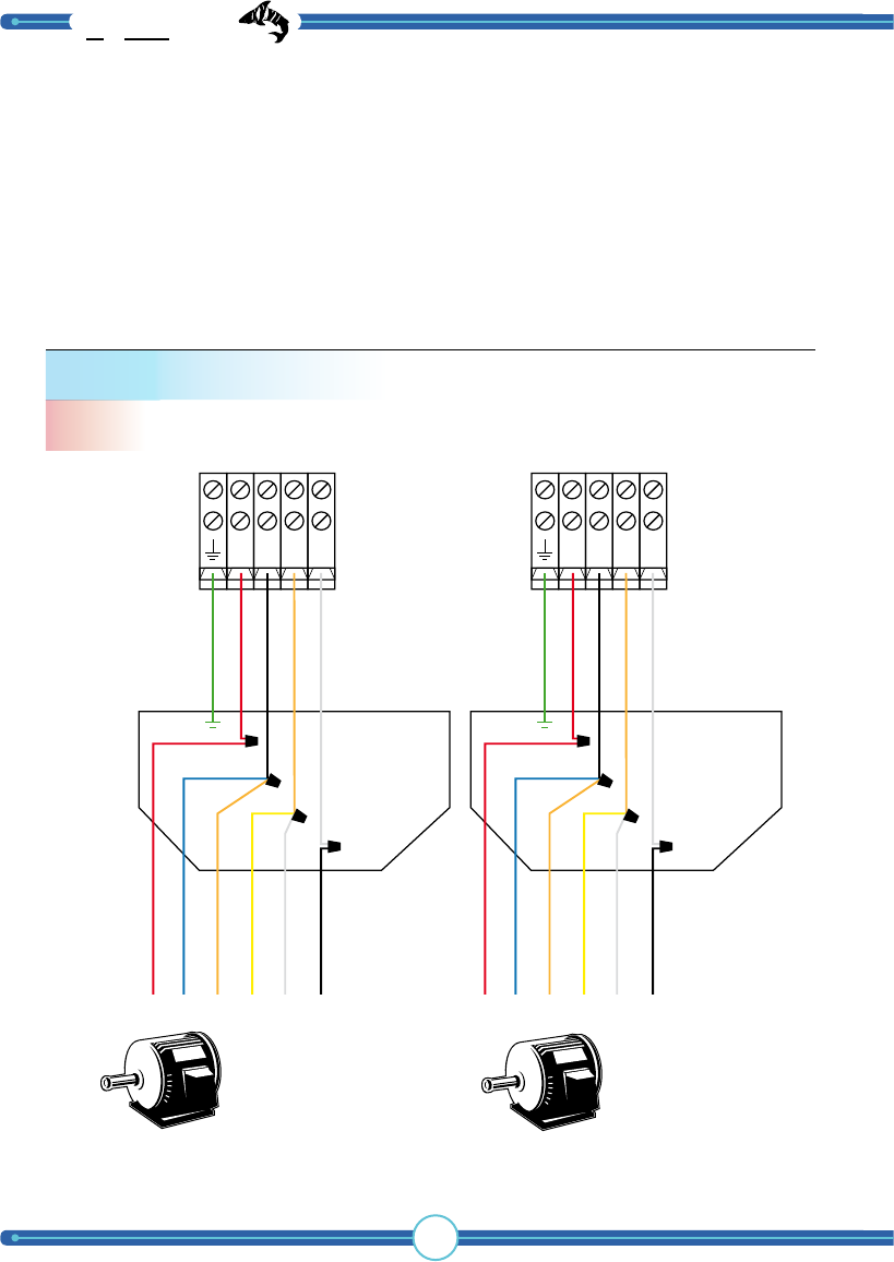
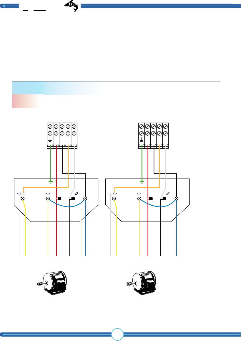
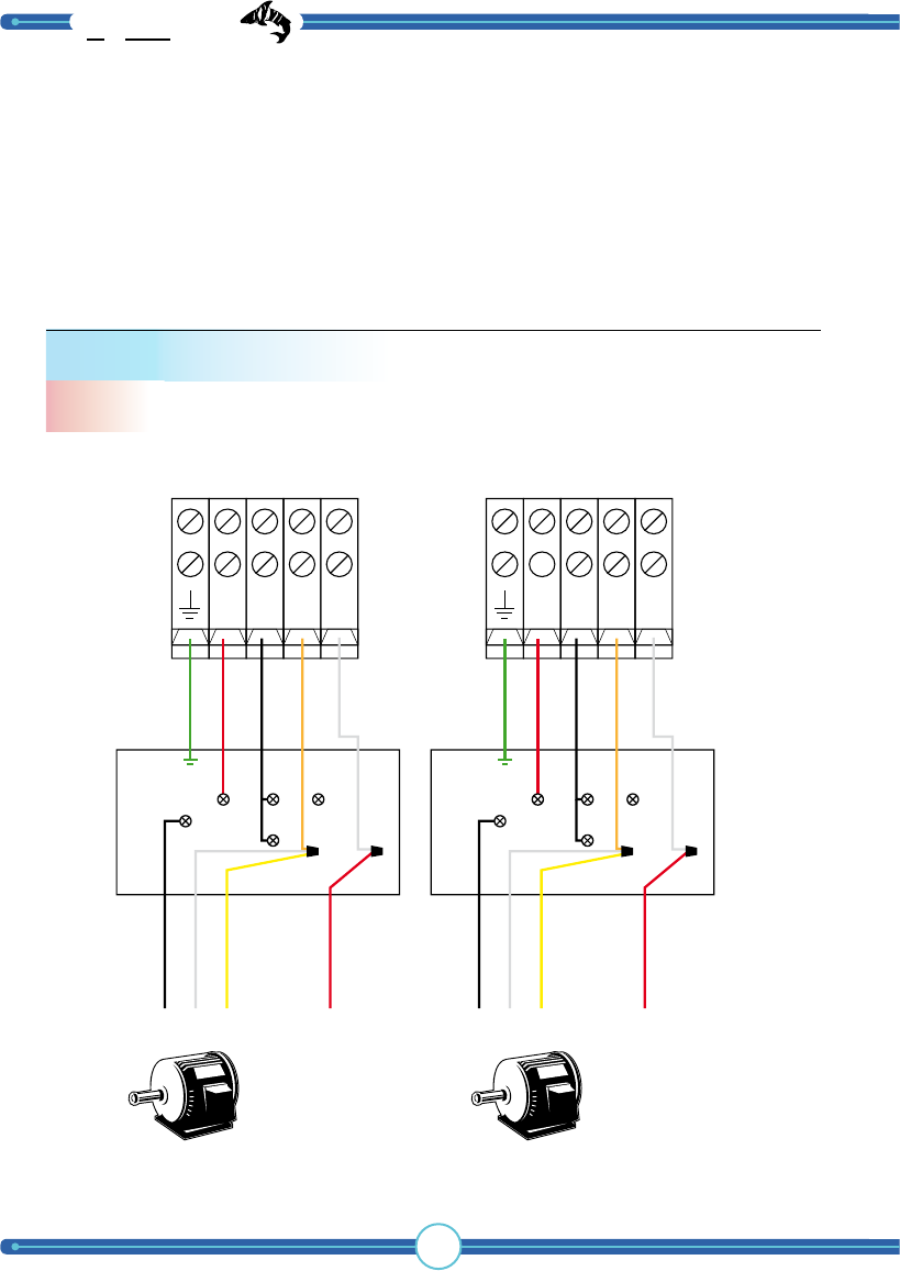
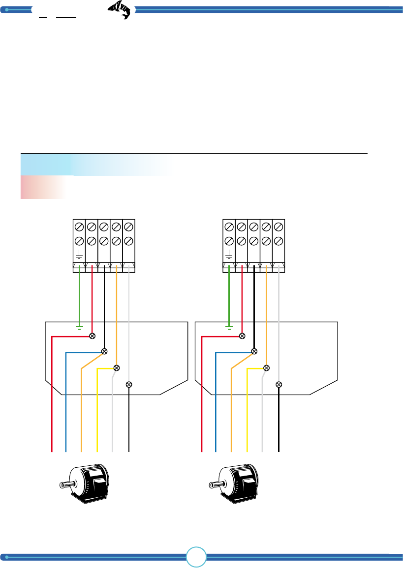
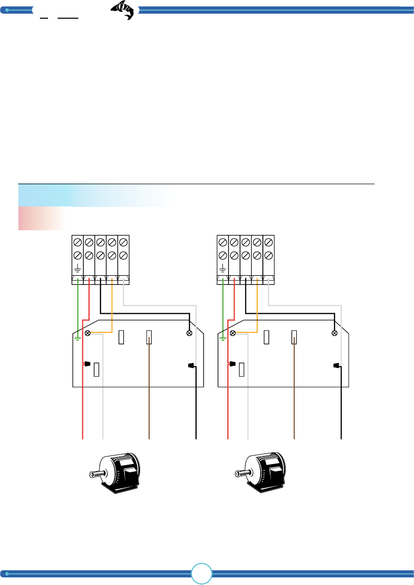
Standard T-motor
120 V
Motor 1 Motor 2
TIP: To change direction, switch T5 & T8.
NR1B1O1
GROUND
RED
BLACK
ORANGE
WHITE
T8
T1
T3
T4
T2
T5
A
B
C
D
NR2B2O2
GROUND
RED
BLACK
ORANGE
WHITE
T8
T1
T3
T4
T2
T5
A
B
C
D
A.O. Smith, Baldor, Dayton, Deco, GE,
Electrogear, Emerson, Leeson, Lincon,
Marathon, SMC and other T-numbered
motor wires.
WARNING: Motor connections shown are to be used as a guide. We require you to
contact your boat lift dealer, motor manufacturer, installer and professional electrician to
double check and verify connections to your boat lift as many motors change over time.
Tele Radio will not be responsible for improper connections.
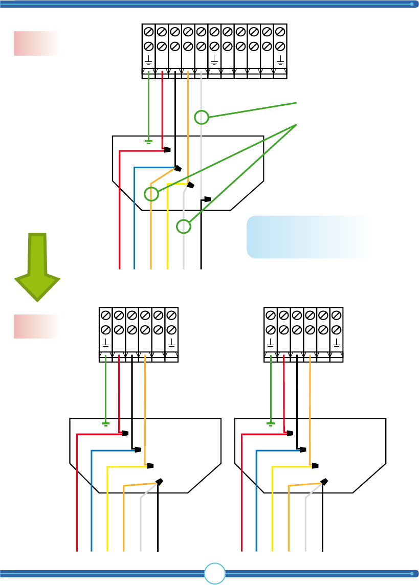
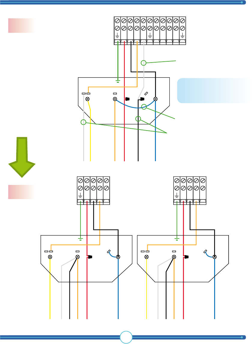
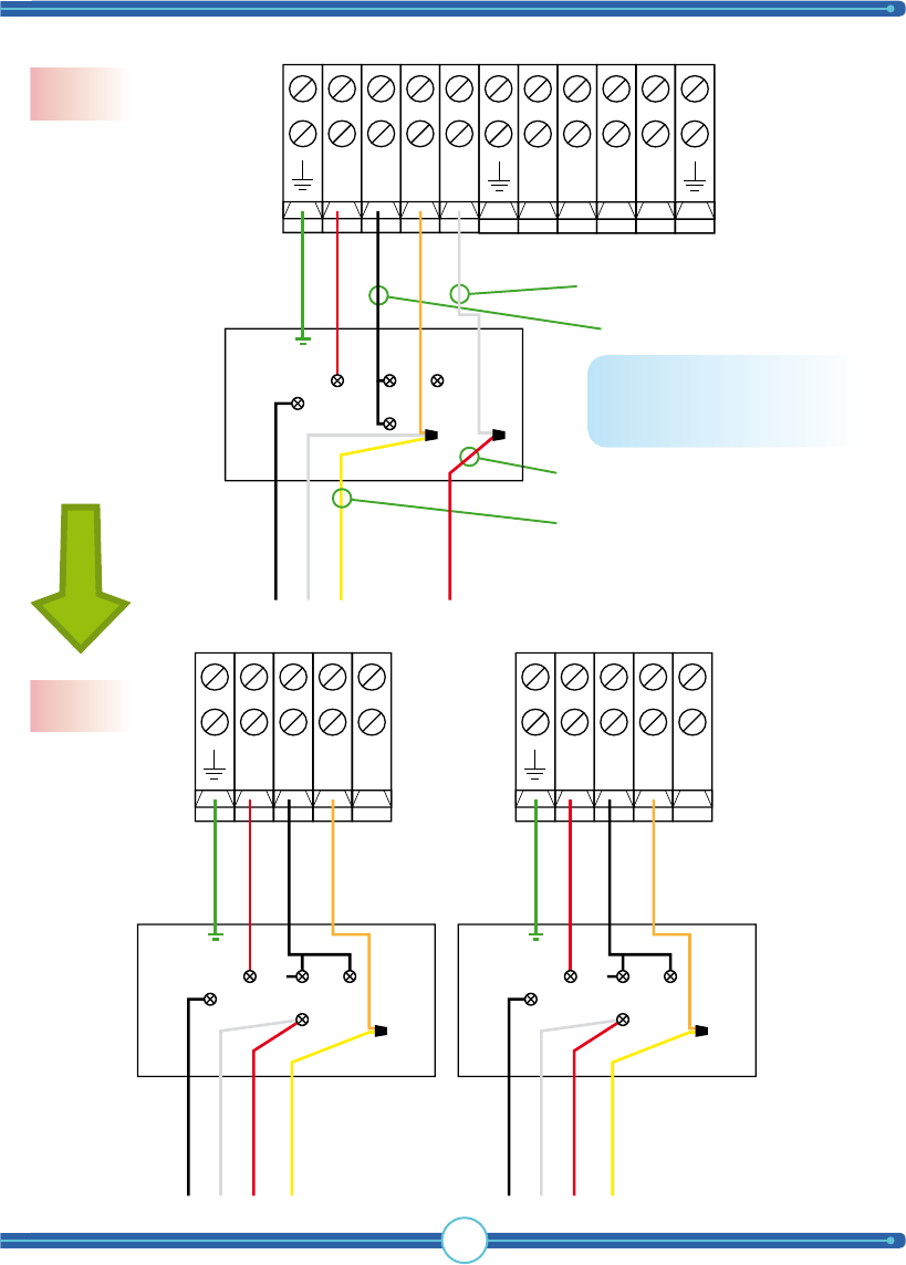
29
NR
1
B
1
O
1
GROUND
RED
BLACK
ORANGE
WHITE
T8
T1
T3
T4
T2
T5
A
B
C
D
NR
1
B
1
O
1
NR
2
B
2
O
2
GROUND
T8
T1
T4
T3
T2
T5
RED
BLACK
ORANGE
A
B
C
D
NR
1
B
1
O
1
GROUND
T8
T1
T4
T3
T2
T5
RED
BLACK
ORANGE
A
B
C
D
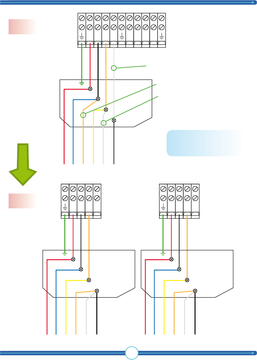
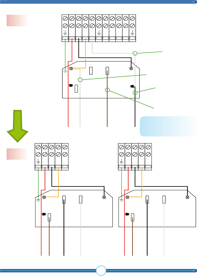
Remove TigerShark WHITE.
Wire together Motor T3 with
Motor T2 & T5 at position
marked “D”.
NOTE: Do this change on
both motors!
Changeover process
120 V
230 V
From 120 V to 230 V
TigerShark
boat lift solutions
30
Eastbay motor
120 V
Motor 1 Motor 2
TIP: To change direction, switch E(RED) & D(Jumper
Wire)
NR1B1O1
1
2
B A 5 D
C 3 E
4
BLUE
RED
GROUND
BLACK
ORANGE
WHITE
YELLOW
NR1B1O1
1
2
B A 5 D
C 3 E
4
BLUE
RED
GROUND
BLACK
ORANGE
WHITE
YELLOW
WARNING: Motor connections shown are to be used as a guide. We require you to
contact your boat lift dealer, motor manufacturer, installer and professional electrician to
double check and verify connections to your boat lift as many motors change over time.
Tele Radio will not be responsible for improper connections.
31
R2B2O2NNR1B1O1
1
2
B A 5 D
C 3 E
4
BLUE
RED
GROUND
BLACK
ORANGE
WHITE
YELLOW
NR1B1O1
1
2
B A 5 D
C 3 E
4
BLUE
RED
GROUND
BLACK
ORANGE
YELLOW
J
U
M
P
E
R
W
I
R
E
NR2B2O2
1
2
B A 5 D
C 3 E
4
BLUE
RED
GROUND
BLACK
ORANGE
YELLOW
J
U
M
P
E
R
W
I
R
E
Move Motor YELLOW cable
from “5” to “4”
Move Motor BLUE cable
from “2” to “3”
Move TigerShark ORANGE
cable from “D” to “C”.
Add a JUMPER WIRE between
“B” and “D”.
Move TigerShark RED cable
from “A” to “E”
Remove the WHITE cable
between “N” and “B”
Move TigerShark BLACK cable
from “E” to “A”.
NOTE: Do this change on
both motors!
Changeover process
120 V
230 V
From 120 V to 230 V
TigerShark
boat lift solutions
32
AO Smith motor
120 V
NR1B1O1
GROUND
RED
BLACK
ORANGE
WHITE
Motor WHITE
Motor YELLOW
Motor ORANGE
Motor RED
Motor BLACK
Motor BLUE
1 2 3 5
L2 L14
NR2B2O2
GROUND
RED
BLACK
ORANGE
WHITE
Motor WHITE
Motor YELLOW
Motor ORANGE
Motor RED
Motor BLACK
Motor BLUE
1 2 3 5
L2 L14
Motor 1 Motor 2
TIP: To change direction, switch MOTOR RED & BLACK.
WARNING: Motor connections shown are to be used as a guide. We require you to
contact your boat lift dealer, motor manufacturer, installer and professional electrician to
double check and verify connections to your boat lift as many motors change over time.
Tele Radio will not be responsible for improper connections.
33
NR1B1O1R2B2O2N
GROUND
RED
BLACK
ORANGE
WHITE
Motor WHITE
Motor YELLOW
Motor ORANGE
Motor RED
Motor BLACK
Motor BLUE
1 2 3 5
L2 L14
GROUND
RED
BLACK
ORANGE
Motor YELLOW
Motor ORANGE
Motor BLACK
Motor WHITE
Motor RED
Motor BLUE
NR1B1O1
1 2 3 5
L2 L14
Remove the TigerShark WHITE.
Move Motor BLACK and wire
together with Motor WHITE and ORANGE
cable at position marked “4”.
Move jumper from position “4” to
position “5”
GROUND
RED
BLACK
ORANGE
Motor YELLOW
Motor ORANGE
Motor BLACK
Motor WHITE
Motor RED
Motor BLUE
NR2B2O2
1 2 3 5
L2 L14
NOTE: Do this change on
both motors!
Changeover process
120 V
230 V
From 120 V to 230 V
TigerShark
boat lift solutions
34
Leeson Balldor motor
230 V
GROUND
T8
T1
T4
T3
T2
T5
RED
BLACK
ORANGE
GROUND
T8
T1
T4
T3
T2
T5
RED
BLACK
ORANGE
R2B2O2
R1B1O1
NOT
USED
NOT
USED
NN
Motor 1 Motor 2
TIP: To change direction, switch T8 & T5.
WARNING: Motor connections shown are to be used as a guide. We require you to
contact your boat lift dealer, motor manufacturer, installer and professional electrician to
double check and verify connections to your boat lift as many motors change over time.
Tele Radio will not be responsible for improper connections.
35
NR1B1O1R2B2O2N
NR1B1O1
GROUND
T8
T1
T3
T4
T2
T5
RED
BLACK
ORANGE
WHITE
NR2B2O2
GROUND
T8
T1
T3
T4
T2
T5
RED
BLACK
ORANGE
WHITE
GROUND
T8
T1
T4
T3
T2
T5
RED
BLACK
ORANGE
Add a WHITE cable to “N” and wire
together with Motor T5
Wire together cable T3 with
cable T1 and TigerShark BLACK
Wire together cable T2
with cable T4 and
TigerShark ORANGE
NOTE: Do this change on
both motors!
Changeover process
120 V
230 V
From 120 V to 230 V
TigerShark
boat lift solutions
36
General Electric motor
120 V
R1B1O1N
GROUND
RED
BLACK
ORANGE
WHITE
Motor BLACK
Motor WHITE
Motor YELLOW
Motor RED
12
A
5
4
R2B2O2N
GROUND
RED
BLACK
ORANGE
WHITE
Motor BLACK
Motor WHITE
Motor YELLOW
Motor RED
12
A
5
4
Motor 1 Motor 2
TIP: To change direction, switch MOTOR RED & BLACK.
WARNING: Motor connections shown are to be used as a guide. We require you to
contact your boat lift dealer, motor manufacturer, installer and professional electrician to
double check and verify connections to your boat lift as many motors change over time.
Tele Radio will not be responsible for improper connections.
37
NR1B1O1
GROUND
RED
BLACK
ORANGE
Motor BLACK
Motor WHITE
Motor RED
Motor YELLOW
12
A
5
4
NR2B2O2
GROUND
RED
BLACK
ORANGE
Motor BLACK
Motor WHITE
Motor RED
Motor YELLOW
12
A
5
4
Remove TigerShark WHITE cable.
Move Motor RED cable and wire
together Motor WHITE.
Move Motor YELLOW cable and wire
together Motor ORANGE.
Move and connect TigerShark BLACK
from “5” to “4”.
R2B2O2N
R1B1O1N
GROUND
RED
BLACK
ORANGE
WHITE
Motor BLACK
Motor WHITE
Motor YELLOW
Motor RED
12
A
5
4
NOTE: Do this change on
both motors!
Changeover process
120 V
230 V
From 120 V to 230 V
TigerShark
boat lift solutions
38
Century Magnatech motor
120 V
R2B2O2N
NOT
USED
GROUND
RED
BLACK
ORANGE
Motor RED
Motor BLUE
Motor YELLOW
Motor WHITE
Motor ORANGE
2 1 6 5
4
Motor BLACK
R1B1O1N
GROUND
RED
BLACK
WHITE
ORANGE
Motor RED
Motor WHITE
Motor YELLOW
Motor WHITE
Motor BLACK
2 1 6 5
4
Motor ORANGE
Motor 1 Motor 2
TIP: To change direction, switch MOTOR RED & BLACK.
WARNING: Motor connections shown are to be used as a guide. We require you to
contact your boat lift dealer, motor manufacturer, installer and professional electrician to
double check and verify connections to your boat lift as many motors change over time.
Tele Radio will not be responsible for improper connections.
39
R
2
B
2
O
2
N
R1B1O1N
GROUND
RED
BLACK
WHITE
ORANGE
Motor RED
Motor WHITE
Motor YELLOW
Motor WHITE
Motor BLACK
2 1 6 5
4
Motor ORANGE
NR1B1O1
GROUND
RED
BLACK
ORANGE
Motor RED
Motor BLUE
Motor YELLOW
Motor WHITE
Motor ORANGE
2 1 6 5
4
Motor BLACK
NR2B2O2
GROUND
RED
BLACK
ORANGE
Motor RED
Motor BLUE
Motor YELLOW
Motor WHITE
Motor ORANGE
2 1 6 5
4
Motor BLACK
Remove the TigerShark WHITE.
Move Motor WHITE and Motor Orange and
wire together at position “5”.
NOTE: Do this change on
both motors!
Changeover process
120 V
230 V
From 120 V to 230 V
TigerShark
boat lift solutions
40
Emerson motor
120 V
NR1B1O1
GROUND
Motor RED
Motor BLUE
Motor ORANGE
Motor YELLOW
Motor WHITE
Motor BLACK
RED
BLACK
ORANGE
WHITE
2
3
1
4
NR2B2O2
GROUND
Motor RED
Motor BLUE
Motor ORANGE
Motor YELLOW
Motor WHITE
Motor BLACK
RED
BLACK
ORANGE
WHITE
2
3
1
4
Motor 1 Motor 2
TIP: To change direction, switch MOTOR RED & BLACK.
WARNING: Motor connections shown are to be used as a guide. We require you to
contact your boat lift dealer, motor manufacturer, installer and professional electrician to
double check and verify connections to your boat lift as many motors change over time.
Tele Radio will not be responsible for improper connections.
41
NR1B1O1R2B2O2N
GROUND
Motor RED
Motor BLUE
Motor ORANGE
Motor YELLOW
Motor WHITE
Motor BLACK
RED
BLACK
ORANGE
WHITE
2
3
1
4
NR1B1O1
GROUND
RED
BLACK
ORANGE
Motor RED
Motor BLUE
Motor YELLOW
Motor ORANGE
Motor WHITE
Motor BLACK
2
3
1
4
NR1B1O1
GROUND
RED
BLACK
ORANGE
Motor RED
Motor BLUE
Motor YELLOW
Motor ORANGE
Motor WHITE
Motor BLACK
2
3
1
4
Remove TigerShark WHITE cable.
Move Motor ORANGE and wire together with
Motor WHITE and BLACK at position “4”.
Move Motor WHITE to “1”.
Changeover process
120 V
230 V
From 230 V to 120 V
NOTE: Do this change on
both motors!
TigerShark
boat lift solutions
42
Leeson motor
120 V
R1B1O1N
GROUND
BLACK
3
1
4
6
2
5
RED
ORANGE
WHITE
Motor BLUE
Motor BROWN
Motor PURPLE
Motor YELLOW
R1B1O1N
GROUND
BLACK
3
1
4
6
2
5
RED
ORANGE
WHITE
Motor BLUE
Motor BROWN
Motor PURPLE
Motor YELLOW
Motor 1 Motor 2
TIP: To change direction, switch ORANGE & BLACK.
WARNING: Motor connections shown are to be used as a guide. We require you to
contact your boat lift dealer, motor manufacturer, installer and professional electrician to
double check and verify connections to your boat lift as many motors change over time.
Tele Radio will not be responsible for improper connections.
43
R1B1O1N
GROUND
BLACK
3
1
4
6
2
5
RED
ORANGE
WHITE
Motor BLUE
Motor BROWN
Motor PURPLE
Motor YELLOW
R2B2O2N
NR
1
B
1
O
1
GROUND
BLACK
3
1
4
6
2
5
RED
ORANGE
Motor BLUE
Motor BROWN
Motor PURPLE
Motor YELLOW
Remove TigerShark WHITE cable.
Move Motor PURPLE to “5”. Move Motor BROWN to “5”.
NR
2
B
2
O
2
GROUND
BLACK
3
1
4
6
2
5
RED
ORANGE
Motor BLUE
Motor BROWN
Motor PURPLE
Motor YELLOW
NOTE: Do this change on
both motors!
Changeover process
120 V
230 V
From 230 V to 120 V
TigerShark
boat lift solutions
44
Baldor motor
120 V
R1B1O1N
GROUND
Motor RED / T8
Motor WHITE / T2
Motor BROWN / J
BLACK
RED
ORANGE
WHITE
L2 L1
3
4
Motor BLACK / T5
R1B1O1N
GROUND
Motor RED / T8
Motor WHITE / T2
Motor BROWN / J
BLACK
RED
ORANGE
WHITE
L2 L1
3
4
Motor BLACK / T5
Motor 1 Motor 2
TIP: To change direction, switch Motor RED / T8 and Motor BLACK / T5
WARNING: Motor connections shown are to be used as a guide. We require you to
contact your boat lift dealer, motor manufacturer, installer and professional electrician to
double check and verify connections to your boat lift as many motors change over time.
Tele Radio will not be responsible for improper connections.
45
Changeover process
120 V
230 V
From 230 V to 120 V
R
2
B
2
O
2
N
R
1
B
1
O
1
N
GROUND
Motor RED / T8
Motor WHITE / T2
Motor BROWN / J
BLACK
RED
ORANGE
WHITE
L2 L1
3
42
2
Motor BLACK / T5
NR
1
B
1
O
1
L1
3
4
GROUND
Motor RED / T8
Motor WHITE / T2
Motor BROWN / J
BLACK
RED
ORANGE
WHITE
L2
Motor BLACK / T5
Remove TigerShark WHITE .
Move Motor BLACK / T5 to “2”.
Move Motor
BROWN / J to “3”
Move Motor WHITE / T2 to “4”.
2
NR
2
B
2
O
2
L1
3
4
GROUND
Motor RED / T8
Motor WHITE / T2
Motor BROWN / J
BLACK
RED
ORANGE
WHITE
L2
Motor BLACK / T5
NOTE: Do this change on
both motors!

TigerShark
boat lift solutions
46
Appendix
2-motor lifts
Internal connection schematic and
wiring charts
WARNING! This section of the
manual is only for licensed electricians and
installers. Interference with high-voltage
equipment is illegal for individuals without
the required training/authorization.
Your TigerShark unit has been delivered how it appears on the following page
(Delivery design). Before connecting power you must first determine what AC
voltage your boat lift requires and then proceed to change the wiring accordingly.
In the following pages you will find all the different voltages that can be available at
your location. Contact your boat lift manufacturer for further assistance.
WARNING
Hazardrous voltage
Contact may cause
electric shock or burn.
Disconnect power
before servicing.
WARNING
Hazardrous voltage
Wrongful handling may cause
electric shock or burn.
Can only be installed
by licensed electrician.
47
2 4 6
L3 L2 L1
L1 L2 L3 L1 L2 L3
1 3 5 N
N
1 2 3 4
230V
Isolate
MOTOR 1LIMIT SWITCH
NR1B1O1R2B2O2N
MOTOR 2
INCOMING GROUND
INCOMING PHASE 1 (120V)
INCOMING NEUTRAL (N)
120V
US 120 VAC
(1 phase, 120 VAC)
Delivery design WARNING
Hazardrous voltage
Contact may cause
electric shock or burn.
Disconnect power
before servicing.
WARNING
Hazardrous voltage
Wrongful handling may cause
electric shock or burn.
Can only be installed
by licensed electrician.
Connection schematics
TigerShark
boat lift solutions
48
Add the second 120V
phase to position “2”.
Delivery design, US 120 VAC -> US 230 VAC (2 phase, 120 VAC)
Change instructions
2 4 6
L3 L2 L1
L1 L2 L3 L1 L2 L3
1 3 5 N
N
1 2 3 4
230V
Isolate
NR1B1O1R2B2O2N
INCOMING PHASE 1 (120V)
INCOMING NEUTRAL (N)
120V
Move the red conductor
to position “3”.
49
2 4 6
L3 L2 L1
L1 L2 L3 L1 L2 L3
1 3 5 N
N
1 2 3 4
230V
Isolate
MOTOR 1LIMIT SWITCH
NR1B1O1R2B2O2N
MOTOR 2
INCOMING GROUND
INCOMING PHASE 2 (120V)
INCOMING PHASE 1 (120V)
INCOMING NEUTRAL (N)
120V
Connection schematic WARNING
Hazardrous voltage
Contact may cause
electric shock or burn.
Disconnect power
before servicing.
WARNING
Hazardrous voltage
Wrongful handling may cause
electric shock or burn.
Can only be installed
by licensed electrician.
US 230 VAC
(2 phase, 120 VAC)
TigerShark
boat lift solutions
50
2 4 6
L3 L2 L1
L1 L2 L3 L1 L2 L3
1 3 5 N
N
1 2 3 4
230V
Isolate
NR1B1O1R2B2O2N
INCOMING PHASE 1 (120V)
INCOMING NEUTRAL (N)
120V
Delivery design US 120 VAC -> 1 phase, 230 VAC
Disconnect the black 120V
conductor and isolate. Connect
the brown 230V conductor to
the right contactor “L2”.
Change instructions
51
Connection schematic
1 phase, 230 VAC
WARNING
Hazardrous voltage
Contact may cause
electric shock or burn.
Disconnect power
before servicing.
WARNING
Hazardrous voltage
Wrongful handling may cause
electric shock or burn.
Can only be installed
by licensed electrician.
2 4 6
L3 L2 L1
L1 L2 L3 L1 L2 L3
1 3 5 N
N
1 2 3 4
Isolate
MOTOR 1LIMIT SWITCH
NR1B1O1R2B2O2N
MOTOR 2
INCOMING GROUND
INCOMING PHASE 1 (230V)
INCOMING NEUTRAL (N)
120V
230V

TigerShark
boat lift solutions
52
PAGE INTENTIONALLY LEFT BLANK

53
PAGE INTENTIONALLY LEFT BLANK
TigerShark
boat lift solutions
54
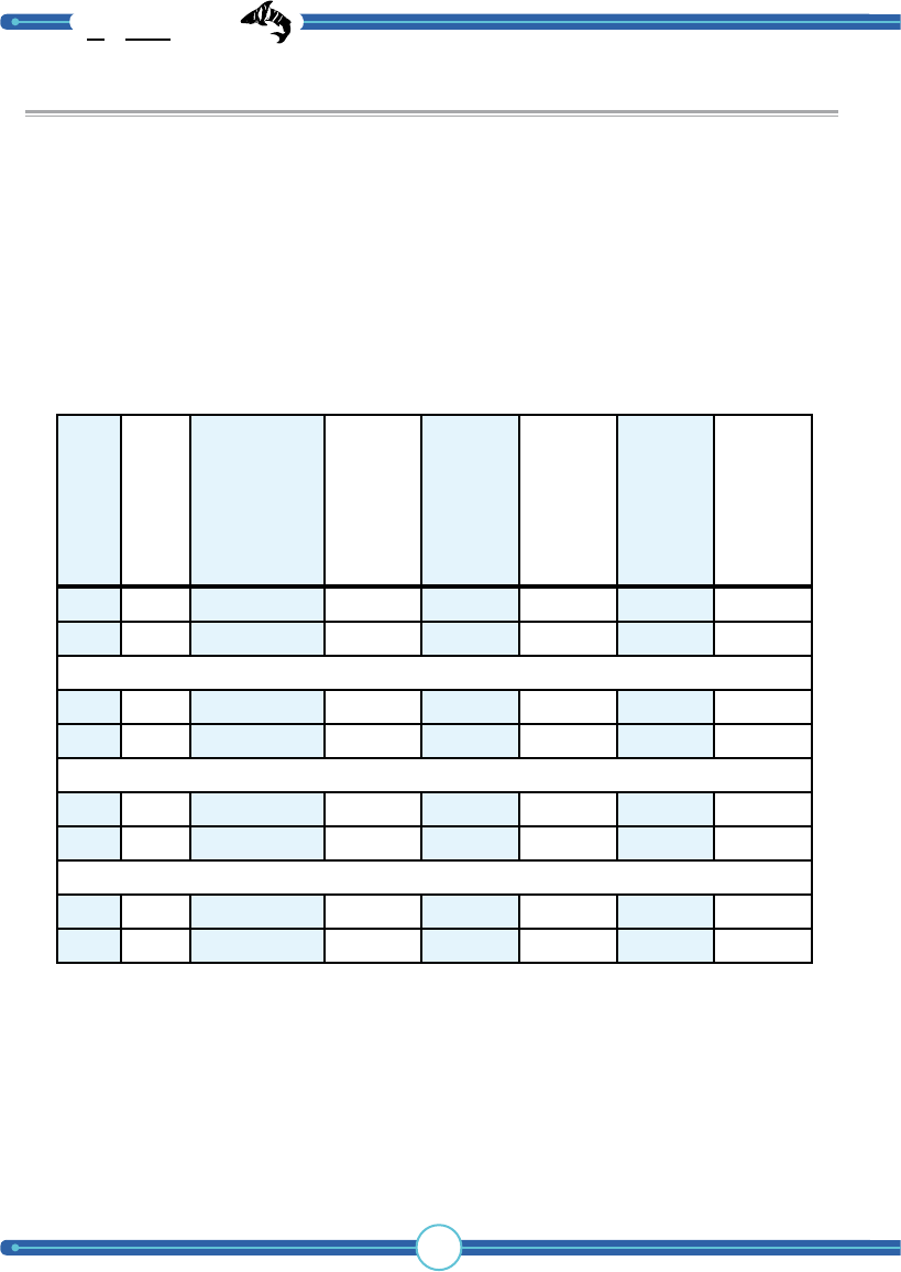
Wire size recommendation chart
½ 1 10A (8,8A) 12 10 6 4 4
220A (17,6A) 10 6 4 2 1
¾ 1 15A (10,8A) 12 8 6 4 3
225A (21,6A) 8 6 3 1 -
1 1 15A (12,8A) 10 8 6 4 3
230A (25,6A) 8 4 2 1 -
1-½ 1 20A (17,1A) 10 6 4 2 1
235A (34,4A) 6 4 1 - -
Motor HP
# Motors
Breaker size
15 m
50 feet
30 m
100 feet
60 m
200 feet
90 m
300 feet
120 m
400 feet
(actual current)
120 V AC - 1 phase
WARNING! Use the below chart for proper wire size. Using the wrong sized wires
might damage your motors and the TigerShark unit.

55
½ 1 5A (4,4A) 14 14 12 10 10 6
210A (5,4A) 12 12 10 8 6 3
420A (17,6A) 12 10 6 4 4 2
¾ 1 10A (5,4A) 14 13 12 12 10 6
215A (10,8A) 12 12 10 8 6 3
425A (21,3A) 12 8 6 4 3 1
1 1 10A (6,4A) 14 14 12 12 10 6
215A (12,8A) 12 10 8 6 4 1
430A (26,0A) 10 8 4 3 2 1
1-½ 1 10A (8,5A) 14 14 10 10 8 4
220A (17,0A) 12 10 8 4 2 1
440A (36,1A) 10 6 4 2 1 1/0
2 4 45A (44,8A) 8 6 3 1 1/0 -
Motor HP
# Motors
Breaker size
15 m
50 feet
30 m
100 feet
60 m
200 feet
90 m
300 feet
120 m
400 feet
240 m
800 feet
(actual current)
230 V AC - 2 phase
TigerShark
boat lift solutions
56
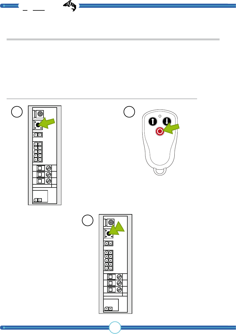
Pairing a transmitter to the TigerShark
Situations might arise where you want to add a transmitter to the TigerShark boat
lift (i.e. if you have lost a transmitter or you want to add another transmitter).
The RED led inside
will flash three
times. The pairing
process is complete.
3
Pairing a transmitter (performed in the TigerShark control box and with a transmitter)
Press and hold the
learn button for
about a second.
The RED led inside
should turn on.
1Press the red
button on the
transmitter.
2
57
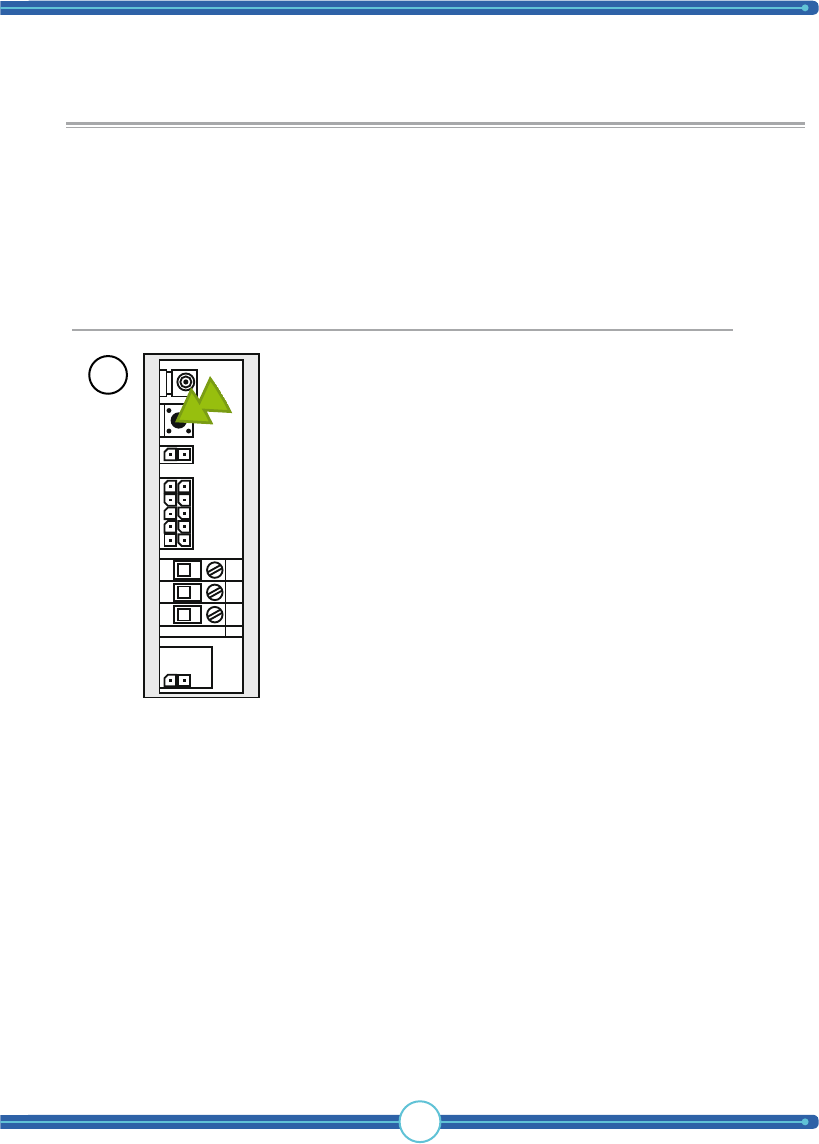
Deleting transmitters for the TigerShark
Situations might arise where you want to add a delete all the transmitters for the
TigerShark boat lift.
Locate the radio
unit in the box.
Press and hold the
learn button for
about six seconds.
The RED led inside
should turn off.
All the transmitters
are now removed
from memory.
1
Deleting transmitters (performed in the TigerShark control box and with a transmitter)
TigerShark
boat lift solutions
58
Appendix
4-motor lifts
Internal connection schematic and
wiring charts
WARNING! This section of the
manual is only for licensed electricians and
installers. Interference with high-voltage
equipment is illegal for individuals without
the required training/authorization.
Your TigerShark unit has been delivered how it appears on the following page
(Delivery design). Before connecting power you must first determine what AC
voltage your boat lift requires and then proceed to change the wiring accordingly.
In the following pages you will find all the different voltages that can be available at
your location. Contact your boat lift manufacturer for further assistance.
WARNING
Hazardrous voltage
Contact may cause
electric shock or burn.
Disconnect power
before servicing.
WARNING
Hazardrous voltage
Wrongful handling may cause
electric shock or burn.
Can only be installed
by licensed electrician.
59
Before connecting power you must first determine what AC voltage your boat
lift requires. Contact your boat lift manufacturer for further assistance.
230 VAC
(2 phase, 120 VAC) WARNING
Hazardrous voltage
Contact may cause
electric shock or burn.
Disconnect power
before servicing.
WARNING
Hazardrous voltage
Wrongful handling may cause
electric shock or burn.
Can only be installed
by licensed electrician.
L1 L2 L3 L1 L2 L3
2 4 6
1 3 5 N
N
120V
230V
ISOLATE
1 R1B1O1R2B2O2R3B3O3R4B4O4
2 3
MOTOR 1 MOTOR 2 MOTOR 3 MOTOR 4LIMIT SWITCH
INCOMING GROUND
INCOMING PHASE 1 (120V)
INCOMING PHASE 2 (120V)
INCOMING NEUTRAL (N)
L1 L2 L3
Connection schematics
TigerShark
boat lift solutions
60
www.tele-radio.com
14895 NE 20th Ave Toll free phone 1-866-629-0780
North Miami FL 33181 Toll free fax 1-866-254-5850
usa@tele-radio.com
IM-TS-001-A10
MODIFICATION STATEMENT:
Caution: The user is cautioned that changes or modifications not expressly ap-
proved by the party responsible for compliance could void the user’s authority
to operate the equipment.
15.105 CLASS B DIGITAL DEVICE OR PERIPHERAL
Note: This equipment has been tested and found to comply with the limits for
a Class B digital device, pursuant to part 15 of the FCC Rules. These limits are
designed to provide reasonable protection against harmful interference in a
residential installation. This equipment generates, uses and can radiate radio
frequency energy and, if not installed and used in accordance with the instruc-
tions, may cause harmful interference to radio communications. However, there
is no guarantee that interference will not occur in a particular installation. If this
equipment does cause harmful interference to radio or television reception,
which can be determined by turning
the equipment off and on, the user is encouraged to try to correct the interfer-
ence by one or more of the following measures:
- Reorient or relocate the receiving antenna.
- Increase the separation between the equipment and receiver.
- Connect the equipment into an outlet on a circuit different from that to which
the receiver is connected.
- Consult the dealer or an experienced radio/TV technician for help.
FCC compliance statement