Tele Radio C1108A Radio module User Manual
Tele Radio AB Radio module
ONFC1108A & 4807A-C1108A User Manual
Tele Radio
FCC-IM-TG-RX007-B01-EN
ARTICLE CODE: R00004-03, R00004-08, T0009-12
LANGUAGE: ENGLISH (ORIGINAL)
SAFETY INSTRUCTIONS
Thank you for purchasing a Tele Radio product
R00004-03, R00004-08, T0009-12
READ ALL INSTRUCTIONS CAREFULLY BEFORE MOUNTING, INSTALLING AND
CONFIGURATING THE PRODUCT.
These instructions are published by Tele Radio AB without any guarantee. These
!"#$%&'$!("#)*%+)#(,+,-).!%+'$+.)$(/*%.#)0&*,!1+.)!"#$*,,+%#2)34+)!"5(%6*$!(")#4*,,)"($)7+)
handed to end users. 34+)!"#$%&'$!("#)6*-)7+)%+6(8+.)(%)%+8!#+.)7-)3+,+)%*.!()9:)*$)
*"-)$!6+)*".)/!$4(&$)*"-)5&%$4+%)"($!'+2);(%%+'$!("#)*".)*..!$!("#)/!,,)7+)*..+.)$()$4+)
&<.*$+.)8+%#!("#)(5)$4+)!"#$%&'$!("#2)
34+)!"#$%&'$!("#)$4*$)'("$*!")!"5(%6*$!(")(")$4+)!"#$*,,*$!(")*".)'("1=&%*$!(")(5)$4+)
%+6($+)%*.!()'("$%(,)&"!$)(")$4+)6*'4!"+)*%+)"($)!"$+".+.)$()7+)<*##+.)(")$()$4+)+".)
&#+%2)>",-)#&'4)!"5(%6*$!(")6*-)7+)<*##+.)(")$()$4+)+".)&#+%?)$4*$)!#)"++.+.)$()(<+%*$+)
$4+)6*'4!"+)'(%%+'$,-)7-)%*.!()%+6($+)'("$%(,2)
3+,+)@*.!()9:)<%(.&'$#)*%+)'(8+%+.)7-)*)=&*%*"$++)*=*!"#$)6*$+%!*,?)'("#$%&'$!(")(%)
6*"&5*'$&%!"=)5*&,$#2)A&%!"=)$4+)=&*%*"$++)<+%!(.?)3+,+)@*.!()9:)6*-)%+<,*'+)$4+)<%(.&'$)
(%)5*&,$-)<*%$#)/!$4)"+/2))B(%C)&".+%)=&*%*"$++)6&#$)7+)'*%%!+.)(&$)7-)3+,+)@*.!()9:)
(%)7-)*")*&$4(%!D+.)#+%8!'+)'+"$%+)#<+'!1+.)7-)3+,+)@*.!()9:2)E*C+)#&%+)$4*$)%+<*!%#)*".)
6*!"$+"*"'+)*%+)(",-)'*%%!+.)(&$)7-)0&*,!1+.)<+%#(""+,2))F#+)(",-)#<*%+)<*%$#)5%(6)3+,+)
@*.!()9:2);("$*'$)-(&%)3+,+)@*.!()%+<%+#+"$*$!8+)!5)-(&)"++.)#&<<(%$)(%)#+%8!'+2)
©Tele Radio AB, 2012
TELE RADIO AB
A*$*8G=+")HI?)JKLMNO)NH)9#C!62)J/+.+")
3+,P)QMOLNILRMS)TM)OU))
V*WP)QMOLNILOS)TM)OM)
///2$+,+L%*.!(2'(62)
info
@
$+,+L%*.!(2'(6

4
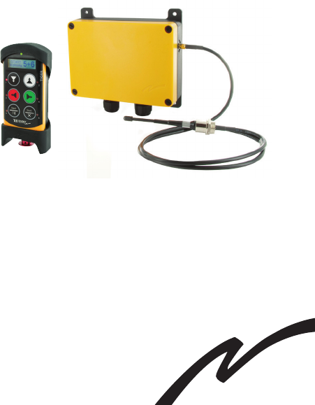
RECEIVER
TECHNICAL DATA
E*W!6&6)'&%%+"$)'("#&6<$!("
RX MODEL 12 V DC 24V DC 48V AC 230V AC
R00004-03 HSU)69 IMU)69 IMU)69 HU)69
R00004-08 TUU)69 HMU)69 HNU)69 TU69
RELAYS:
R00004-03 H)#*5+)%+,*-#)X6*C+#Y7%+*C#)) )
) ) ) IO9)9;Z[)Q)R)5&"'$!(")%+,*-#)X<($+"$!*,))
) ) ) 5%++\?6*C+#Y7%+*C#)S9)9;Z[2)
R00004-08 H)#*5+)%+,*-#)X6*C+#Y7%+*C#)) )
) ) ) IO9)9;Z[)Q)IR)5&"'$!(")%+,*-#)X<($+"$!*,))
) ) ) 5%++\?6*C+#Y7%+*C#)S9)9;Z[2)
OPERATING FREQUENCY: ]UN2UIHTL]HO2]SRT)E^D2
V@K_FK`;a):9`bJP) IT)7*"C#
JZcKP)))))) ) ) RT)W)IHO)W)IRO)662Y)
) ) ) H]2T”)W)M]2O”)W)O]2N”
BKZd^3P)))) ) IUUU)=%*6#Y)H2H),7#2
K`;9eJFf93Z>`)Ze);f9JJP) ZeOT
\)<($+"$!*,)5%++)6+*"#)$4*$)-(&)4*8+)$()#&<<,-)8(,$*=+)$()=+$)8(,$*=+)(&$)(5)*)%+,*-)X+2=2)8!*)*)
'(""+'$!(")'(67[2)
IMPORTANT!)B+)%+'(66+".)$4*$)$4+)5&"'$!("*,!$-)(5)$4+)J3>e)7&$$(")!#)7+!"=)
$+#$+.)*$)*)%+=&,*%)7*#!#P)9$)*)6!"!6&6?)/4+")&#+.)5(%)HUU)4(&%#2)3+#$)$4+)J3>e)
button by pressing and pulling it out.
STOP BUTTON TEST
T
AC AC
48-230V 12-24V
AC/DC
+/AC
-/GND
+/AC
SR1 SR2 1 2 3 4567
1 2 3 4 5 6 8 9 10 11 12 13 14 15 16 17 18 19 20 21 22 23 24 25 26 27 28 29 30 317
32 33 34 35 36 37 38 39 40 41 42 43
R1
SR1 SR2 R2 R3 R4 R5 R6 R7
LED1
LED2
LED3
LED4
LED5
LED6
LED7
LED6
LED7
LED3
LED2LED1
SR 1+2
LED LED4 LED5
LED1
LED8
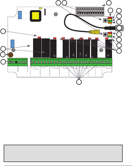
1. Stop relays 1+2 LED (red)
2. Stop relays 1+2
N2)>7,!=*$(%-)5&#+P)H9)X#,(/[?)6&#$)))))
)))'(6<,-)/!$4)ZK;O]IYK`OUO]I
M2)3+%6!"*,)7,('C)5(%)<(/+%)#&<<,-)))
(see next page)
T2)V&"'$!(")%+,*-#)ILR
O2)@+,*-)fKA#ILR)X%+.[
7. Function LED 7 (green)
S2)V&"'$!(")fKA)O)X-+,,(/[
]2))V&"'$!(")fKA)T)X%+.[
10. Antenna connector
11.Function LED 4 (orange)
12. Function LED 3 (green)
13. Function LED 2 (yellow)
14. Function LED 1 (red)
IT2)3+%6!"*,)7,('C)5(%)6!W+.)ZY>#
IO2)V&"'$!(")7&$$(")
(Cancel button)
17. Select button (OK button)
2
3
4
T
O
7
9
11
12
13
8
14
IT
IO17
10
1
RECEIVER TG-R00004-03, TG-R00004-08
BASE BOARD
IMPORTANT!
3+,+)@*.!()%+6($+)'("$%(,#)*%+)(5$+")7&!,$)!"$()/!.+%)*<<,!'*$!("#2)B+)%+'(66+".)$4*$)
$4+)#-#$+6)!#)<%(8!.+.)/!$4)*)/!%+.)+6+%=+"'-)#$(<)/4+%+)"+'+##*%-2
O
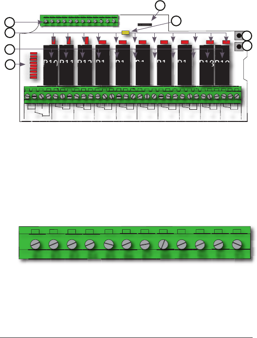
TG-R00004-08
10 RELAYS EXPANSION BOARD
81. GND
82. GND
83. GND
84. GND
ST2)A!=!$*,)!"<&$)N
SO2)A!=!$*,)!"<&$)M
SR2)A!=!$*,)!"<&$)T
SS2)A!=!$*,)!"<&$)O
89. Digital input 7
90. Digital input 8
91. Digital input 9
92. Digital input 10
R6
10 11 12 13 14 15 16 17 18 19
51 52 53 54 55 56 57 58 59 60 61 62 63 64 65 66 67 68 69 70 71 72 73 74 75 76 77 78 79 80
51
50
R10 R11 R12 R13 R14 R15 R16 R17 R18
R19
LED1
LED20
LE
D
1
1
LED2
LED2
2
2
2
LED3
LED
3
3
3
3
LED4
LED4
4
4
LED4
4
4
4
4
LED5
LED
5
5
LED
5
5
5
5
5
LED6
LED
6
6
LED
6
6
6
6
6
6
LED7
LED
7
7
LED
7
7
7
7
7
7
LED8
LED
8
LED
8
8
8
8
LED9
1
0
L
E
D
1
1
L
E
D
1
2
L
E
D
1
3
L
E
D
LE
D
2
0
1
4
L
E
D
1
5
L
E
D
1
6
L
E
D
1
7
L
E
D
1
8
L
E
D
1
9
L
E
D
52
2
1
5
1
3
3
5
50
0
5
0
1
5
3
5
52
2
52
5
3
5
1
1
54
54
5
5
55
5
56
57
57
54
5
1
2
7
58
59
9
57
1
3
0
61
62
60
14
63
63
64
4
65
6
6
15
6
6
6
6
67
68
8
6
6
66
66
16
69
9
6
70
0
71
1
72
7
6
17
2
73
7
74
72
7
1
8
75
5
75
5
76
7
77
7
78
75
19
8
8
8
8
79
9
80
8
78
78
IS2)3+%6!"*,)7,('C)5(%).!=!$*,)!"<&$#
19. Relay LEDs 10-19
20. Function relays 10-19
21. Relay LEDs 1-9 (see next page)
22. Select button (OK)
23. Function button (Cancel)
HM2):*#+)7(*%.)'(66&"!'*$!("L)) ))))))
LED (yellow)
HT2)e%(=%*66!"=)'(""+'$(%
IS2)3+%6!"*,)7,('C)5(%).!=!$*,)!"<&$#
18
20
21
23
24
HT
22
19
81 82 83 84 85 86 87 88 89 90 91 92
81 82 83 84 85 86 87 88 89 90 91 92

7
LED 1
LED 2
LED 3
LED 4
LED 5
LED 6
LED 7
LED 8
LED 9
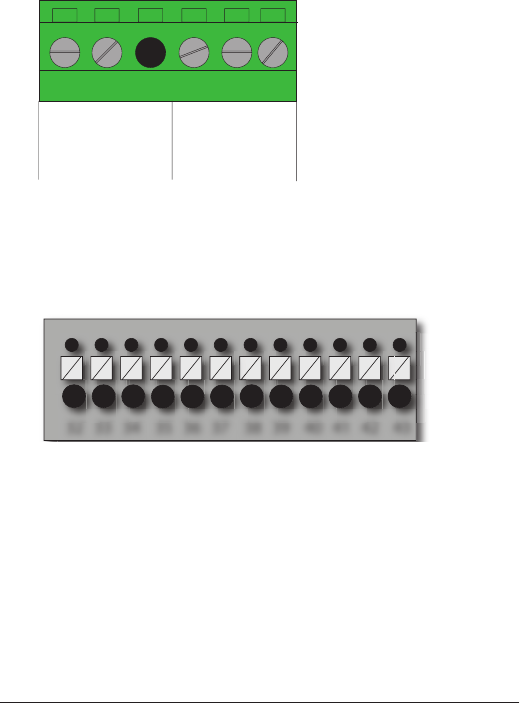
LED 1= function relay 1
LED 2= function relay 2
LED 3= function relay 3
LED 4= function relay 4
fKA)Tg)5&"'$!(")%+,*-)T
fKA)Og)5&"'$!(")%+,*-)O
LED 7= function relay 7
LED 8= not used
LED 9= stop relay 1+2
LEDs 1-9 on the expansion board indicate the status of the relays on the
7*#+)7(*%.2)B4+")("+)(%)6(%+)(5)$4+#+)fKA#)*%+),!$?)$4+)'(%%+#<(".!"=)
%+,*-)(")$4+)7*#+)7(*%.)!#)*'$!8*$+.)X#++),!#$[2)
21. Relay LEDs 1-9
8
32 33 34 35 36 37 38 39 40 41 42 43
AC AC
48-230V AC 12-24V
AC/DC
+/AC
-/GND
+/AC
1 2 3 4 5 6
1. 48-230V AC
2. 48-230V AC
3. (not used)
M2)IHLHMh)9;YA;
T2)d`A
O2)IHLHMh)9;YA;
32. +12V DC
NN2)QTh)A;
34. GND
NT2)d`A
NO2)A!=!$*,)!"<&$)I
37. Buzzer
38. Digital input 2
39. GND
40. +3.3V DC
MI2)@JMST9
MH2)@JMST:
43. GND
IT2)3+%6!"*,)7,('C)5(%)6!W+.)ZY>#
4. Input power
V(%)A;)8(,$*=+#P
;(""+'$)<(#!$!8+)8(,$*=+)$()M)(%)O2);(""+'$)"+=*$!8+)8(,$*=+)$()T2)
9
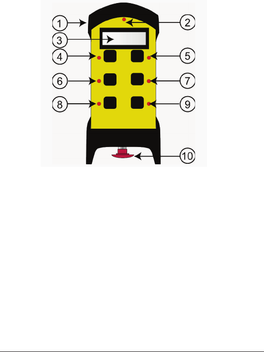
TRANSMITTER T0009-12
I2)@&77+%)'(8+% 7. Button 4
2. Top LED S2):&$$(")T)X#$*%$)7&$$("[
3. Display ]2):&$$(")O)X#$*%$)7&$$("[
4. Button 1 10. Stop button
T2):&$$(")H
O2):&$$(")N

10
START UP IN OPERATING MODE
1. Pull out the stop button.
The top LED lights (green when the battery capacity is good, red
when the battery capacity is poor).
2. BZ3^Z`)N)EZ`F3KJP)e%+##)7&$$(")T)Q)O)*$)$4+)#*6+)$!6+2
The buzzer beeps.
3. @+,+*#+)7&$$(")TQO2
)))))))))34+)7&DD+%)#$(<#)7++<!"=2)34+)$(<)fKA)i*#4+#)X=%++")/4+")$4+)
battery capacity is good, red when the battery capacity is poor).
ENTER THE TRANSMITTER CONFIGURATION MENU
1. Pull out the stop button.
The top LED lights (green when the battery capacity is good, red
when the battery capacity is poor).
2. e%+##)7&$$(")O2)b++<)<%+##+.2)
3. Press the stop button.
4. @+,+*#+)7&$$(")O2)
)))))))))34+)$(<)fKA)i*#4+#)X=%++")/4+")$4+)7*$$+%-)'*<*'!$-)!#)=((.?)%+.))
when the battery capacity is poor).
TURN OFF
1. Press the STOP button.
NOTE! All relays disconnect when the STOP button is
pressed.
11
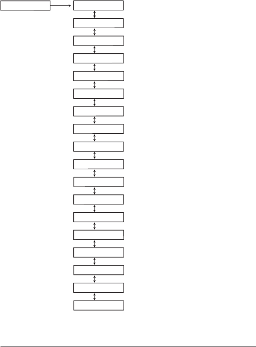
TRANSMITTER CONFIGURATION MENU MAP
>Channel/Bank
>Register
SETTINGS>
>Logout
>Erase
>Replace
>Show receivers
>Auto shutdown
>Load selection
>Startup protection
>Settings protection
>Learn RFID
>Show RFID
>Erase RFID
>Enter PIN
>Show PIN
>Erase PIN
>Show SW vers.
>Test mode

12
NAVIGATE IN THE CONFIGURATION MENU
3()"*8!=*$+)!")$4+)'("1=&%*$!(")6+"&?)<%+##P
Button 1 Step down
Button 2 Step up
Button 3 J$+<),+5$Y)=()7*'C
Button 4 Step right
:&$$(")T J+,+'$Y)'("1%6
:&$$(")O Exit
REGISTER THE TRANSMITTER IN THE RECEIVER
a(&)'*")%+=!#$+%)ILIT)3ZdK@)$%*"#6!$$+%#)!")*)3ZdK@)%+'+!8+%2)K*'4)
$%*"#6!$$+%)4*#)*)&"!0&+)ZA)'(.+2
1. e%+##)$4+)%+'+!8+%)V&"'$!(")7&$$("2
))))))))V&"'$!(")fKA)I)i*#4+#)%+.2)
2. @+,*-)fKA#)ILR),!=4$)$()#4(/)4(/)6*"-)$%*"#6!$$+%#)$4*$)*%+)
*,%+*.-)%+=!#$+%+.)!")$4+)%+'+!8+%2
3. e%+##)$4+)%+'+!8+%)J+,+'$)7&$$(")5(%),+##)$4*")M)#+'(".#)$()+"$+%)
%+=!#$+%!"=)6(.+2)34+)%+'+!8+%)/!,,)#$*-)!")%+=!#$+%!"=)6(.+)5(%)I)
6!"&$+)(%)&"$!,)*)$%*"#6!$$+%)4*#)7++")%+=!#$+%+.2
4. e&,,)(&$)$4+)#$(<)7&$$(")(")$4+)$%*"#6!$$+%2)
T2) e%+##)$%*"#6!$$+%)7&$$(")O2)b++<)<%+##+.2)
O2) Press the stop button.
7. @+,+*#+)7&$$(")O2)
)))))))))34+)$(<)fKA)i*#4+#)X=%++")/4+")$4+)7*$$+%-)'*<*'!$-)!#)=((.?)%+.))
when the battery capacity is poor).
8. d()$()j@+=!#$+%k)!")$4+);("1=&%*$!(")6+"&2)
9. )J+,+'$)7-)<%+##!"=)7&$$(")T2)
10. J+,+'$)*)%+'+!8+%)!")$4+),!#$2)

13
11. ;("1%6)7-)<%+##!"=)7&$$(")T2)
The display shows [Registering] while the process is ongoing.
)))))))))B4+")$4+)%+'+!8+%)4*#)5(&".)$4+)$%*"#6!$$+%?)*,,)%+,*-)fKA#)i*#42)
12. e%+##)$4+)%+'+!8+%)J+,+'$)7&$$("2)
))))))))V&"'$!(")fKA#)ILR)i*#4)N)$!6+#2)34+)%+,*-)fKA#)=()(552)
13. 34+)%+'+!8+%)%+#$*%$#2)
All Function LEDs light for approx. 1 second.
IMPORTANT! For safety reasons, avoid registering transmitters
in receivers where you don´t intend to use it.
ERASE THE TRANSMITTER FROM THE RECEIVER
IMPORTANT! Do not use the erase function during a running
session.
NOTE ! The receiver must be powered during the erase function.
1. e&,,)(&$)$4+)#$(<)7&$$(")(")$4+)$%*"#6!$$+%2)
2. e%+##)$%*"#6!$$+%)7&$$(")O2)b++<)<%+##+.2)
3. Press the stop button.
4. @+,+*#+)7&$$(")O2)
)))))))))34+)$(<)fKA)i*#4+#)X=%++")/4+")$4+)7*$$+%-)'*<*'!$-)!#)=((.?)%+.))
when the battery capacity is poor).
T2) d()$()jK%*#+k)!")$4+);("1=&%*$!(")6+"&2)
O2) )J+,+'$)*)%+'+!8+%)$()+%*#+2)
7. ;("1%6)7-)<%+##!"=)7&$$(")T2)
The display shows [Erasing] while the process is ongoing.
If the erasing fails, the display shows [FAILED]. If the erasing succeeds,
the display shows [OK].
8. 34+)$%*"#6!$$+%)$&%"#)(552)

14
SWITCH FREQUENCY BANK
1. e&,,)(&$)$4+)#$(<)7&$$(")(")$4+)$%*"#6!$$+%2)
2. e%+##)$%*"#6!$$+%)7&$$(")O2)b++<)<%+##+.2)
3. Press the stop button.
4. @+,+*#+)7&$$(")O2)
)))))))))34+)$(<)fKA)i*#4+#)X=%++")/4+")$4+)7*$$+%-)'*<*'!$-)!#)=((.?)%+.))
when the battery capacity is poor).
T2) d()$()j;4*""+,Y:*"Ck)!")$4+);("1=&%*$!(")6+"&2)
O2) J+,+'$)7-)<%+##!"=)7&$$(")T2)
7. 34+)$%*"#6!$$+%)$&%"#)(552)
))))))))B4+")-(&)%+#$*%$)$4+)$%*"#6!$$+%)*5$+%)#/!$'4!"=)5%+0&+"'-?)!$)/!,,))))))))))
)))))))$%*"#6!$)(")$4+)'4*""+,#)!"',&.+.)!")$4+)#+,+'$+.)7*"C2)
CHARGE THE TRANSMITTER BATTERY
BATTERY TYPE:)) ) Z"$+%"*,?)%+'4*%=+*7,+),!$4!&6L!("
CHARGE: With a charger plug in the back of the
) ) ) $%*"#6!$$+%
;^9@dZ`d)3KEeK@93F@KP) Ul;)$()MTl;Y)NHlV)$()IINl
>eK@93Z`d)3ZEKP)) ) 9<<%(W2)IT)42)/!$4)'("$!"&(&#)&#*=+

IT
FCC AND IC INFORMATION
;*&$!("P)34+)&#+%)!#)'*&$!("+.)$4*$)'4*"=+#)(%)6(.!1'*$!("#)"($)
+W<%+##,-)*<<%(8+.)7-)$4+)<*%$-)%+#<("#!7,+)5(%)'(6<,!*"'+)'(&,.)8(!.)
$4+)&#+%m#)*&$4(%!$-)$()(<+%*$+)$4+)+0&!<6+"$2
34!#).+8!'+)'(6<,!+#)/!$4)Z".&#$%-);*"*.*),!'+"'+L+W+6<$)@JJ)
#$*".*%.X#[)*".)e*%$)IT)(5)$4+)V;;)@&,+#2)><+%*$!(")!#)#&7n+'$)$()
$4+)5(,,(/!"=)$/()'(".!$!("#P)XI[)$4!#).+8!'+)6*-)"($)'*&#+)4*%65&,)
!"$+%5+%+"'+?)*".)XH[)$4!#).+8!'+)6&#$)*''+<$)*"-)!"$+%5+%+"'+)%+'+!8+.?)
!"',&.!"=)!"$+%5+%+"'+)$4*$)6*-)'*&#+)&".+#!%+.)(<+%*$!("2
f+)<%o#+"$)*<<*%+!,)+#$)'("5(%6+)*&W);`@).mZ".&#$%!+);*"*.*)*<<,!'*-
7,+#)*&W)*<<*%+!,#)%*.!()+W+6<$#).+),!'+"'+)+$),*)<*%$!+)IT).+#)@p=,+#)
V;;2)fm+W<,(!$*$!(")+#$)*&$(%!#o+)*&W).+&W)'(".!$!("#)#&!8*"$+#)P)
(1) l’appareil ne doit pas produire de brouillage, et
(2) l’utilisateur de l’appareil doit accepter tout brouillage radioélec-
$%!0&+)#&7!?)6q6+)#!),+)7%(&!,,*=+)+#$)#&#'+<$!7,+).m+")'(6<%(6+$$%+),+)
5("'$!(""+6+"$2
34!#)+0&!<6+"$)'(6<,!+#)/!$4)V;;)%*.!*$!(")+W<(#&%+),!6!$#)#+$)5(%$4)
5(%)*")&"'("$%(,,+.)+"8!%("6+"$2)K".)&#+%)6&#$)5(,,(/)$4+)#<+'!1')
(<+%*$!"=)!"#$%&'$!("#)5(%)#*$!#5-!"=)@V)+W<(#&%+)'(6<,!*"'+2)34!#)
$%*"#6!$$+%)6&#$)"($)7+)'(L,('*$+.)(%)(<+%*$!"=)!")'("n&"'$!(")/!$4)
*"-)($4+%)*"$+""*)(%)$%*"#6!$$+%2
;+$)*<<*%+!,)+#$)'("5(%6+)*&W),!6!$+#).m+W<(#!$!(")*&)%*-(""+6+"$)@V)
#$!<&,o+#)<*%),*)V;;)+$),mZ;)<(&%)&"+)&$!,!#*$!(").*"#)&")+"8!%(""+6+"$)
"(")'("$%r,o2)fm&$!,!#*$+&%)1"*,).(!$)#&!8%+),+#)!"#$%&'$!("#).+)5("'$!("-
"+6+"$)#<o'!10&+#)<(&%),+)%+#<+'$).m+W<(#!$!(")*&W)@V2)f+#o6+$$+&%#)
"+).(!8+"$)<*#)q$%+)<,*'o+#)<%p#).m*&$%+#)*"$+""+#)(&)o6+$$+&%#)(&)
5("'$!(""+%)*8+')'+&WL'!2
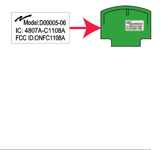
34+)%*.!()6(.&,+)!")$4!#)<%(.&'$)!#),*7+,,+.)/!$4)!$#)(/")V;;)ZA)*".)
Z;)"&67+%2)34+)V;;)ZA)*".)Z;)!#)"($)8!#!7,+)/4+")$4+)%*.!()6(.&,+)!#)
!"#$*,,+.)!"#!.+)*"($4+%).+8!'+2)34+%+5(%+?)$4+)(&$#!.+)(5)$4+).+8!'+)!"$()
/4!'4)$4+)6(.&,+)!#)!"#$*,,+.)6&#$)*,#().!#<,*-)*),*7+,)%+5+%%!"=)$()$4+)
%*.!()6(.&,+2)34+)1"*,)+".).+8!'+)6&#$)7+),*7+,,+.)!")*)8!#!7,+)*%+*)/!$4)
the following:
“Contains FCC ID: ONFC1108A”
“Contains IC: 4807A-C1108A”
or
“Contains FCC ID: ONFC1104B”
“Contains IC: 4807A-C1104B”
IO
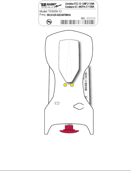
TRANSMITTER PRODUCT LABEL
PLACEMENT
I2)@+6(8+)$4+)%&77+%)'(8+%)7-)4*".2
H2)34+)<%(.&'$),*7+,)/!$4)V;;Y)Z;)!"5(%6*$!(")!#)<,*'+.)$()$4+)%!=4$)(")
$4+)$%*"#6!$$+%)7*'C#!.+)X#++)<!'$&%+[2
1 0
17
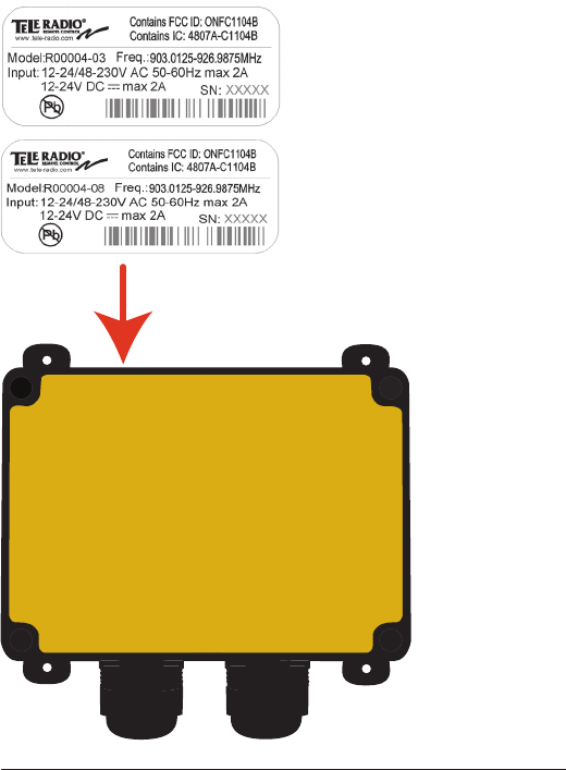
RECEIVER PRODUCT LABEL PLACEMENT
18
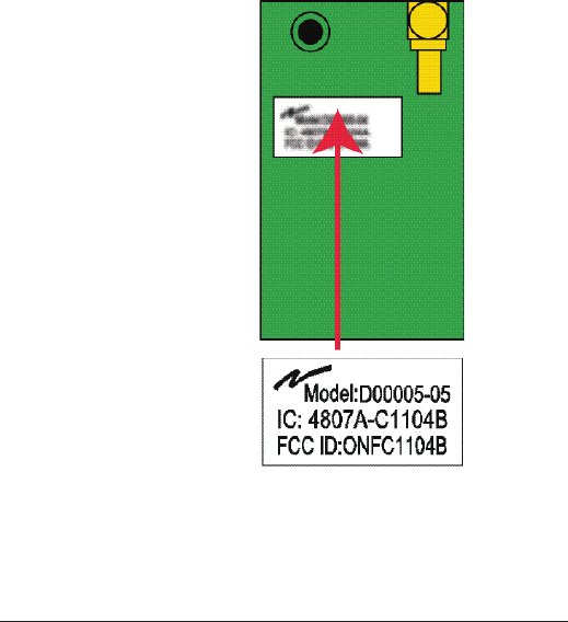
V;;Y)Z;)f9:Kf)ef9;KEK`3)>`
TRANSMITTER
34+)V;;Y)Z;),*7+,)!#)<,*'+.)(")$4+)%*.!()6(.&,+2)34+)%*.!()6(.&,+)!#)
6(&"$+.)!"#!.+)$4+)$%*"#6!$$+%2
fmo$!0&+$$+)V;;YZ;)+#$)<,*'o+)#&%),+)6(.&,+)%*.!(2)f+)6(.&,+)%*.!()+#$)
6("$o)s),m!"$o%!+&%).&)%o'+<$+&%2
19
V;;Y)Z;)f9:Kf)ef9;KEK`3)>`)@K;KZhK@
34+)V;;Y)Z;),*7+,)!#)<,*'+.)(")$4+)%*.!()6(.&,+2)34+)%*.!()6(.&,+)!#)
6(&"$+.)!"#!.+)$4+)%+'+!8+%2
fmo$!0&+$$+)V;;YZ;)+#$)<,*'o+)#&%),+)6(.&,+)%*.!(2)f+)6(.&,+)%*.!()+#$)
6("$o)s),m!"$o%!+&%).+),mo6+$$+&%2

20
THE RADIO MODULE
FUNCTION
K*'4)%+'+!8+%)*".)$%*"#6!$$+%)&"!$)!")$4+)3+,+)@*.!()3!=+%)<%(.&'$)
%*"=+?)'("$*!"#)*)%*.!()6(.&,+)$4*$)!#)#<+'!1'*,,-).+#!="+.)$()6*$'4)*)
3+,+)@*.!()3!=+%)&"!$)!")$+%6#)(5)<4-#!'*,).!6+"#!("#?)'(""+'$!(")<(!"$#?)
8(,$*=+),+8+,#?)#!="*,)!"$+%5*'+)+$'2)3()&#+)$4+)%*.!()6(.&,+#)!")"(")3+,+)
@*.!()<%(.&'$#)!#)"($)<+%6!$$+.2
34+)%*.!()6(.&,+#)*%+).+#!="+.)$()!"$+%5*'+).!%+'$,-)$()$4+)6*!")7(*%.)
(5)$4+)%+'+!8+%Y$%*"#6!$$+%)&"!$2)34+-)*%+)<(/+%)#&<<,!+.)7-)$4+)6*!")
board and the radio circuit operates strictly according to instructions
5%(6)*)6!'%(<%('+##(%)(")$4+)6*!")7(*%.2)34+)%*.!()'!%'&!$)'("1=L
&%*$!(")!#)#$(%+.)!")*)i*#4)6+6(%-)(")$4+)%*.!()6(.&,+2
9)%+'+!8+%Y$%*"#6!$$+%)&"!$)/!$4)*).+5+'$!8+Y"()%*.!()6(.&,+)/!,,)=!8+)
*")+%%(%)6+##*=+)!66+.!*$+,-)*5$+%)<(/+%)&<?)*".)!$)/!,,)"($)7+)
possible to start a radio session.
CROSS REFERENCE
;%(##)%+5+%+"'+)(5)%*.!()6(.&,+#)*".)'(%%+#<(".!"=)<%(.&'$#P
3!=+%)&"!$)@*.!()6(.&,+P)
T0009-* TR224
@UUUML\) 3@HTM

21
INSTALLATION
INSTALLATION INSTRUCTIONS FOR TR224:
I2)E*C+)#&%+)$4*$)$4+)$%*"#6!$$+%)&"!$)!#)$&%"+.)(552
2. Open the T0009-* enclosure.
N2)9##+67,+)3@HHM)$()$4+)H)W)IH)<(,+)#('C+$)'(""+'$(%)(")$4+)7($$(6)
#!.+)(5)$4+)6*!")7(*%.2)
Z`J39ff93Z>`)Z`J3@F;3Z>`J)V>@)3@HTMP
1. Make sure that the unit is turned off.
2. Open the R0004-* enclosure.
N2);(""+'$)$4+)HWIH)<(,+)#('C+$)'(""+'$(%)(5)3@HTM).!%+'$,-)$()$4+)
6*!")7(*%.)(5)@UUUML\2