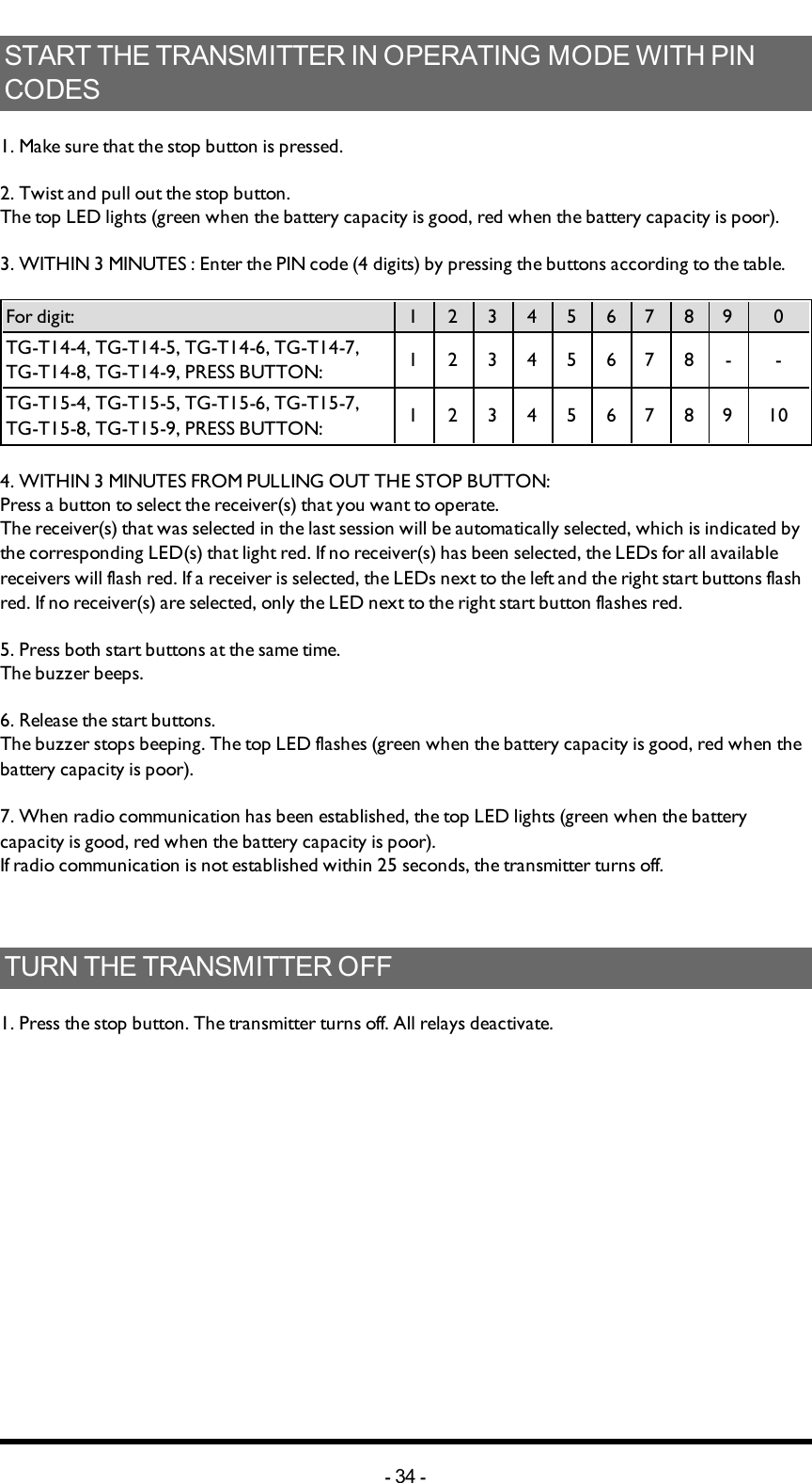
Tele Radio C1406A RF Module User Manual IM TG2 RX002 A10 EN
Tele Radio AB RF Module IM TG2 RX002 A10 EN
UserManual.wiki
>
Tele Radio
>
C1406A User Manual
User Manual
Navigation menu
Upload a User Manual
Namespaces
Wiki Guide
HTML
PDF
Info
Views
User Manual
Discussion / Help
Navigation

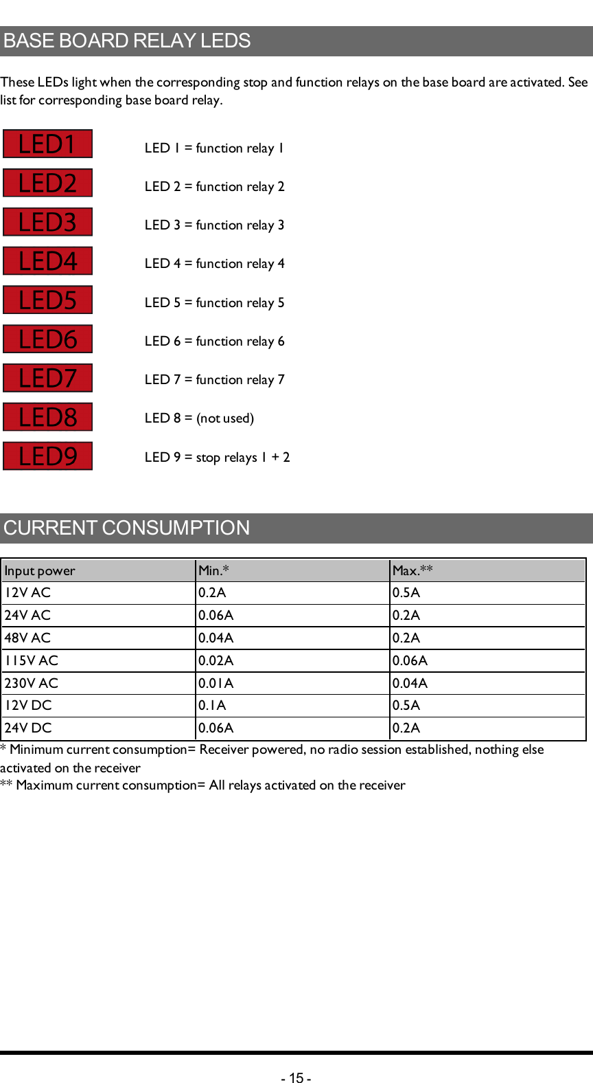
![Chapter 4: INSTALLERS GUIDECHAPTER 4: INSTALLERS GUIDENAVIGATEINMENUMODETo navigate when in menu mode:Press... to...Button 1 Step downButton 2 Step upButton 3 Step left/ go backButton 4 Step rightThe left start button Select/ confirmThe right start button ExitENABLEPINCODES1. Make sure that the stop button is pressed.2. Twist and pull out the stop button.The top LED lights (green when the battery capacity is good, red when the battery capacity is poor).3. Press the right start button. Keep pressed.4. Press the stop button. 5. Release the right start button.The top LED flashes (green when the battery capacity is good, red when the battery capacity is poor) when in menu mode.6. Go to [Startup Protect.].7. Select one or more start-up protection choices by pressing the left start button.Select... to...[Stored PIN] Only accept PIN codes registered in the trans-mitter[Any PIN] Accept any PIN code[Allow skip] Allow to skip any start-up authorization8. Confirm by pressing the left start button.-30 -](https://usermanual.wiki/Tele-Radio/C1406A/User-Guide-2497728-Page-30.png)
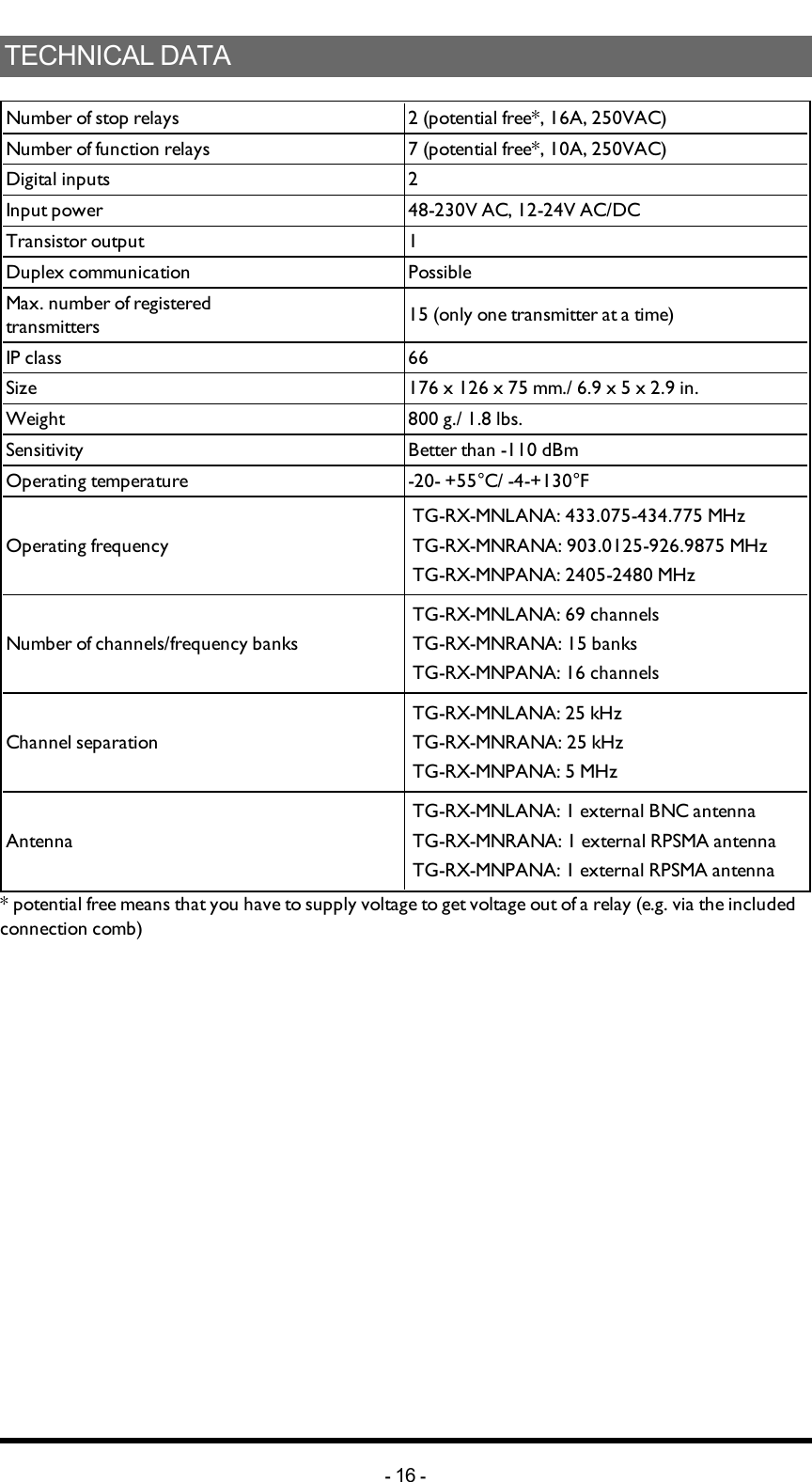
![CREATEPINCODESNOTE! You can store up to 10 PIN codes in the transmitter.NOTE! '0000' is not a valid PIN code.1. Make sure that the stop button is pressed.2. Twist and pull out the stop button.The top LED lights (green when the battery capacity is good, red when the battery capacity is poor).3. Press the right start button. Keep pressed.4. Press the stop button.5. Release the right start button.The top LED flashes (green when the battery capacity is good, red when the battery capacity is poor) when in menu mode.6. Go to [PIN] --> [Enter PIN].7. Select what position in the list that you want to store the new PIN code in by pressing the left start button.8. Enter the new PIN code (4 digits) by pressing the buttons 1-4:Press... to...Button 1 Step upButton 2 Step downButton 3 Step rightButton 4 Step left9. Confirm by pressing the left start button.-31 -](https://usermanual.wiki/Tele-Radio/C1406A/User-Guide-2497728-Page-31.png)
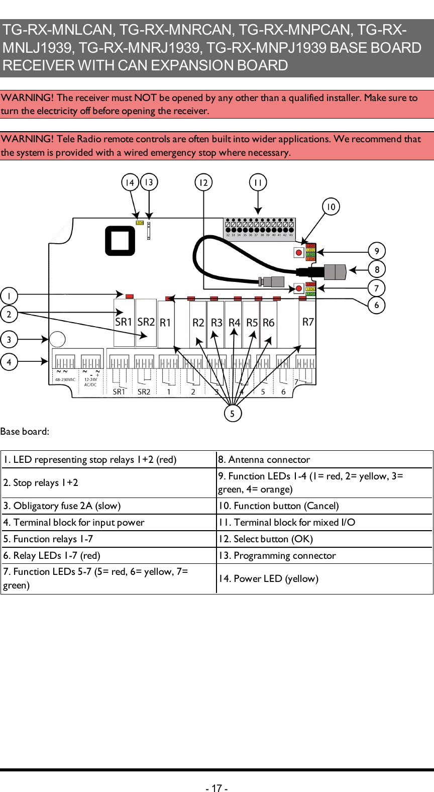
![ERASEPINCODES1. Make sure that the stop button is pressed.2. Twist and pull out the stop button.The LEDs light (green when the battery capacity is good, red when the battery capacity is poor).3. Press the right start button. Keep pressed.4. Press the stop button.5. Release the right start button.The LEDs light (green when the battery capacity is good, red when the battery capacity is poor) when in menu mode. 6. Go to [PIN] --> [Erase PIN].7. Scroll the list to select the PIN code that you want to erase.8. Select by pressing the left start button.9. Confirm by pressing the left start button.SHOWREGISTEREDPINCODES1. Make sure that the stop button is pressed.2. Twist and pull out the stop button.The top LED lights (green when the battery capacity is good, red when the battery capacity is poor).3. Press the right start button. Keep pressed.4. Press the stop button.5. Release the right start button.The top LED flashes (green when the battery capacity is good, red when the battery capacity is poor) when in menu mode.6. Go to [PIN] --> [Show PIN].7. The display shows a list of all registered PIN codes.-32 -](https://usermanual.wiki/Tele-Radio/C1406A/User-Guide-2497728-Page-32.png)
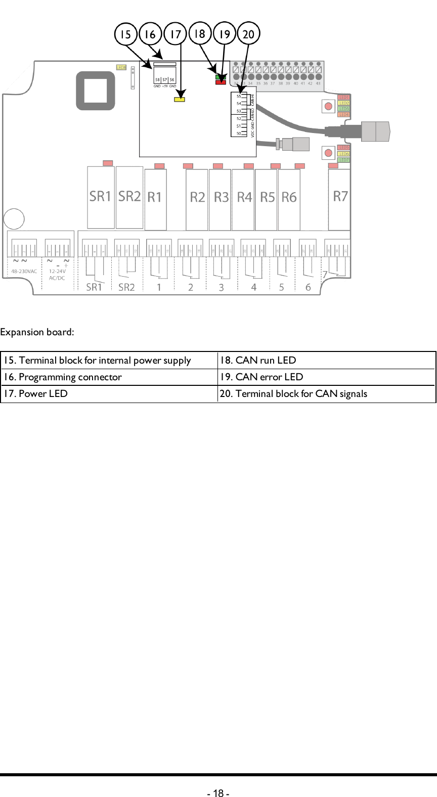
![LOGIN/LOGOUTNOTE! When the transmitter has established radio communication with one or more receivers, you can make a Quick logout from those receivers. Note that the Quick logout will log the transmitter out from all receivers that are participating in the session.NOTE! If you need to log out a transmitter that is lost or damaged, it is possible to log out from the receiver. We do not recommend this way of logging out. Contact your representative for assistance.NOTE! To be able to control a receiver, the transmitter must be registered in the receiver, and logged in to the receiver. If another transmitter is already logged in to the receiver, it has to be logged out before any other transmitter can be logged in. If no transmitter is logged in to a receiver, a registered transmitter will automatically log in when sending radio signals to the receiver. The transmitter will stay logged in until it is manually logged out. More than one transmitter can be registered in the receiver, but only one transmitter can be logged in at a time.Quick logout1. Make sure that the transmitter is started in operating mode.NOTE! The transmitter must have established a radio session with one or more receivers.2. Press the left start button. Keep pressed.3. Press the stop button.4. Release the left start button.The top LED lights red.The display shows [Logging out].The transmitter turns off after logging out.-35 -](https://usermanual.wiki/Tele-Radio/C1406A/User-Guide-2497728-Page-35.png)
![Logout from menu mode1. Make sure that the stop button is pressed.2. Twist and pull out the stop button.The top LED lights (green when the battery capacity is good, red when the battery capacity is poor).3. Press the right start button. Keep pressed.4. Press the stop button.5. Release the right start button.The top LED flashes (green when the battery capacity is good, red when the battery capacity is poor) when in menu mode.6. Go to [Logout].7. Select by pressing the left start button.8. Select a receiver to log out from.9. Confirm by pressing the left start button. The display shows [Logging out...] while the process is ongoing.If logout fails, the display shows [FAILED]. The transmitter turns off.If logout succeeds, the display shows [OK]. The transmitter turns off after logging out.REGISTERWARNING! Do not perform this when the receiver is in a session with another transmitter. The radio communication may become disturbed or broken.NOTE! Before starting to perform these settings, make sure that the stop relays are deactivated!Register the transmitter in the receiver1. Press the receiver Function button.Function LED 1 flashes red.2. Relay LEDs 1-7 light to show how many transmitters that are already registered in the receiver.3. Press the receiver Select button until all relay LEDs light red. The receiver will stay in registering mode for 1 minute or until a transmitter has been registered.4. On the transmitter: Make sure that the stop button is pressed.5. Twist and pull out the stop button.The top LED lights (green when the battery capacity is good, red when the battery capacity is poor).6. Press the right start button. Keep pressed.7. Press the stop button.8. Release the right start button.-36 -](https://usermanual.wiki/Tele-Radio/C1406A/User-Guide-2497728-Page-36.png)
![The top LED flashes (green when the battery capacity is good, red when the battery capacity is poor) when in menu mode. 9. Go to [Register].10. Select an empty slot and confirm by pressing the left start button. The display shows [Registering] .11. When the receiver has found the transmitter, all relay LEDs flash red. The display shows [Confirm on RX]. 12. Press the receiver Select button. Function LEDs 1-7 flash 3 times. The relay LEDs go off. 13. All Function LEDs light for approx. 1 second. The transmitter is now registered in the receiver. The transmitter turns off. 14. If registering fails, the display shows [FAILED]. The transmitter turns off.ERASEWARNING! If a transmitter is lost or becomes seriously damaged, it is possible to erase it from the receiver. We do not recommend this way. Contact your representative for assistance.NOTE! If the transmitter already have receivers registered, we recommend that you erase all receivers from the transmitter before starting the replacement. The receiver will automatically be stored in the same position as it was stored in the old transmitter. If this position is not available, the replacement will not take place. 1. Make sure that the stop button is pressed.2. Twist and pull out the stop button.The top LED lights (green when the battery capacity is good, red when the battery capacity is poor).3. Press the right start button. Keep pressed.4. Press the stop button.5. Release the right start button.The top LED flashes (green when the battery capacity is good, red when the battery capacity is poor) when in menu mode. 6. Go to [Erase].7. Select by pressing the left start button.8. Select a receiver. Confirm by pressing the left start button. The display shows [Erasing] while the process is ongoing.If the erasing fails, the display shows [FAILED]. The transmitter turns off.If the erasing succeeds, the display shows [OK]. The transmitter turns off.-37 -](https://usermanual.wiki/Tele-Radio/C1406A/User-Guide-2497728-Page-37.png)
![REPLACEWARNING! Do not perform this when the receiver is in a session with another transmitter. The radio communication may become disturbed or broken.NOTE! You can replace a registered transmitter with another transmitter without having access to the receiver.NOTE! If the transmitter that needs to be replaced is registered in more than one receiver, it will only be replaced in one receiver at a time. If you want to replace a transmitter in more than one receiver, you need to perform a replacement for each receiver.NOTE! If the transmitter already have receivers registered, we recommend that you erase all receivers from the transmitter before starting the replacement. The receiver will automatically be stored in the same position as it was stored in the old transmitter. If this position is not available, the replacement will not take place.Replace a transmitter with a new transmitter1. Make sure that the stop button is pressed.2. Twist and pull out the stop button.The top LED lights (green when the battery capacity is good, red when the battery capacity is poor).3. Press the right start button. Keep pressed.4. Press the stop button.5. Release the right start button.The top LED flashes (green when the battery capacity is good, red when the battery capacity is poor) when in menu mode.6. Go to [Replace].7. Select by pressing the left start button.8. Enter the serial number/ID code for the transmitter that you want to replace by pressing the buttons according to the table below:Press... to...Button 1 Count -1Button 2 Count +1Button 3 Go leftButton 4 Go right9. Press the left start button.The display shows [Replacing] while the process is ongoing.If the replacement fails, the display shows [FAILED].The transmitter turns off.If the replacement succeeds, the display shows [OK]. The transmitter turns off.-38 -](https://usermanual.wiki/Tele-Radio/C1406A/User-Guide-2497728-Page-38.png)
![AUTOMATICSHUTDOWNNOTE! Turning on automatic shutdown can save battery capacity by automatically turning the transmitter off when no function has been activated for a set time.Set the time for automatic shutdown1. Make sure that the stop button is pressed.2. Twist and pull out the stop button.The top LED lights (green when the battery capacity is good, red when the battery capacity is poor).3. Press the right start button. Keep pressed.4. Press the stop button.5. Release the right start button.The top LED flashes (green when the battery capacity is good, red when the battery capacity is poor) when in menu mode.6. Go to [Auto Shutdown].7. Select by pressing the left start button.8. Select the time that you want for automatic shutdown: 0-255 minutes. If you want to turn off automatic shutdown, select 0.9. Press the left start button.-39 -](https://usermanual.wiki/Tele-Radio/C1406A/User-Guide-2497728-Page-39.png)
![FREQUENCIES&CHANNELSNOTE! If your system is transmitting on the frequency bands 433MHz eller 2.4 GHz, the receiver will automatically detect and switch to the same channel that the transmitter is using. If your system is transmitting on the 915 MHz frequency band, you have to switch bank in the receiver by using the PC program Settings manager. Contact your representative for assistance. Switch channel on the transmitter1. Make sure that the stop button is pressed.2. Twist and pull out the stop button.The top LED lights (green when the battery capacity is good, red when the battery capacity is poor).3. Press the right start button. Keep pressed.4. Press the stop button.5. Release the right start button.The top LED flashes (green when the battery capacity is good, red when the battery capacity is poor) when in menu mode.6. Go to [Channel] or [Bank].7. Go to the frequency table and select a channel.8. Press the left start button.-40 -](https://usermanual.wiki/Tele-Radio/C1406A/User-Guide-2497728-Page-40.png)
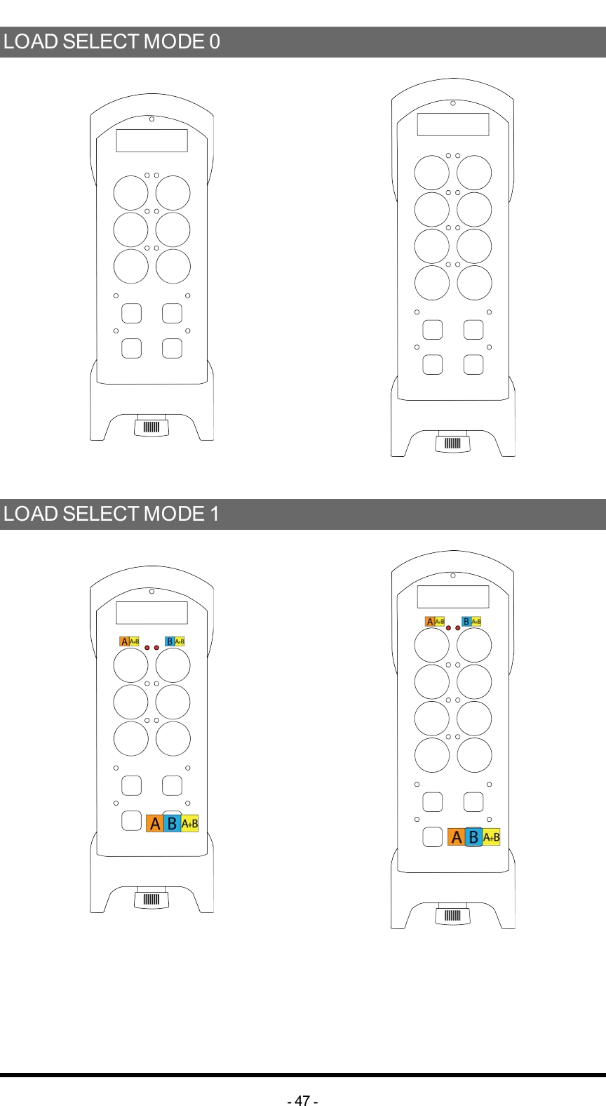
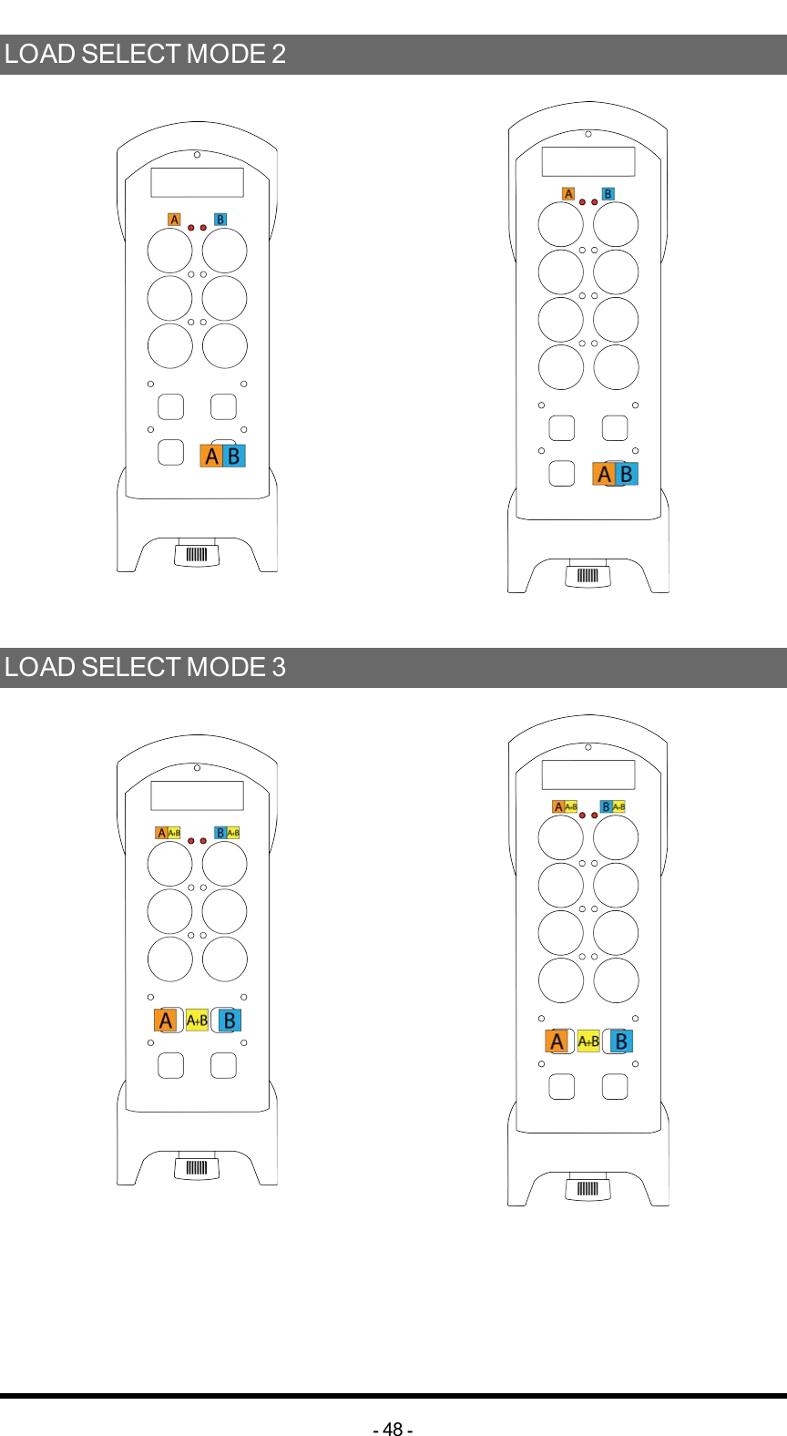
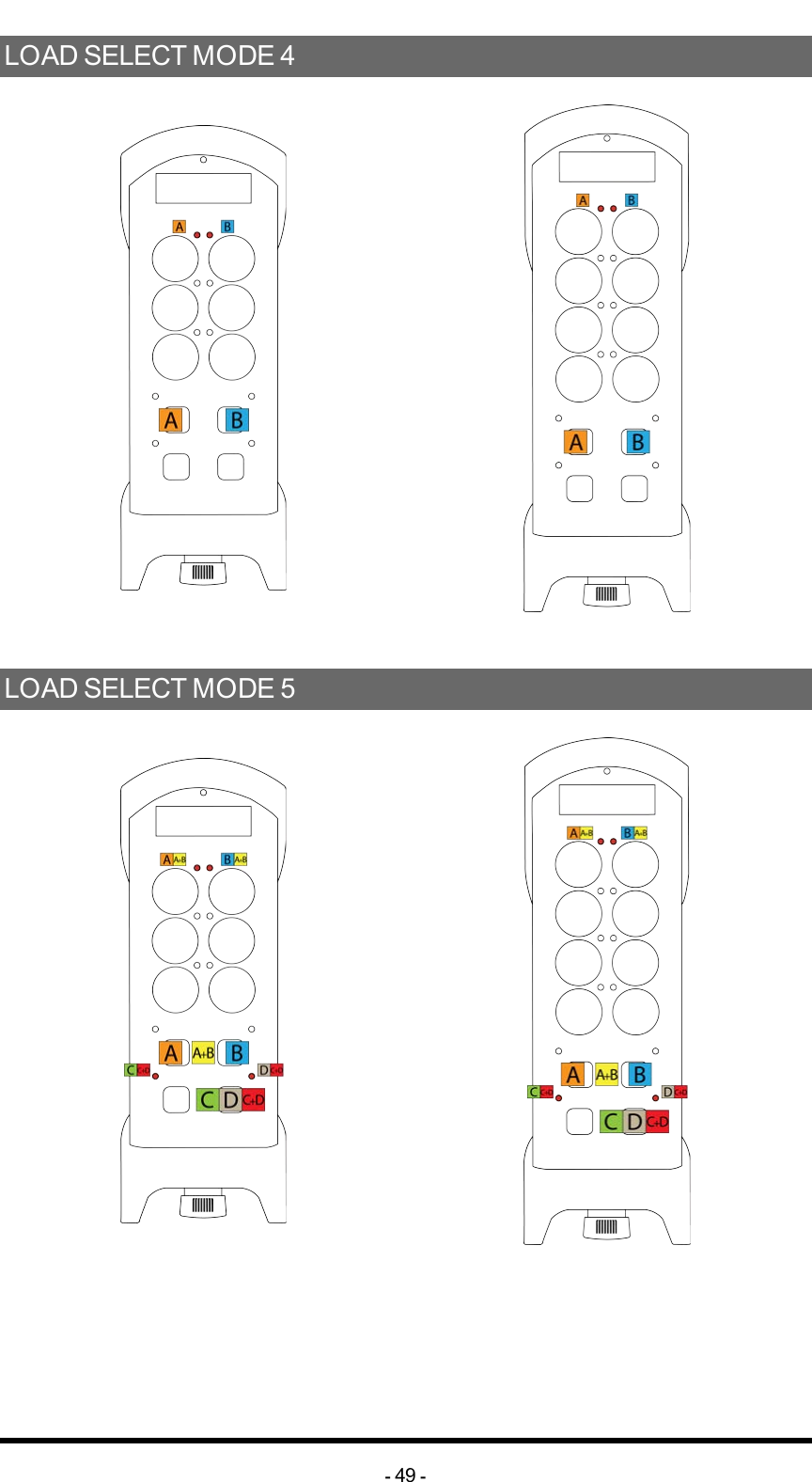
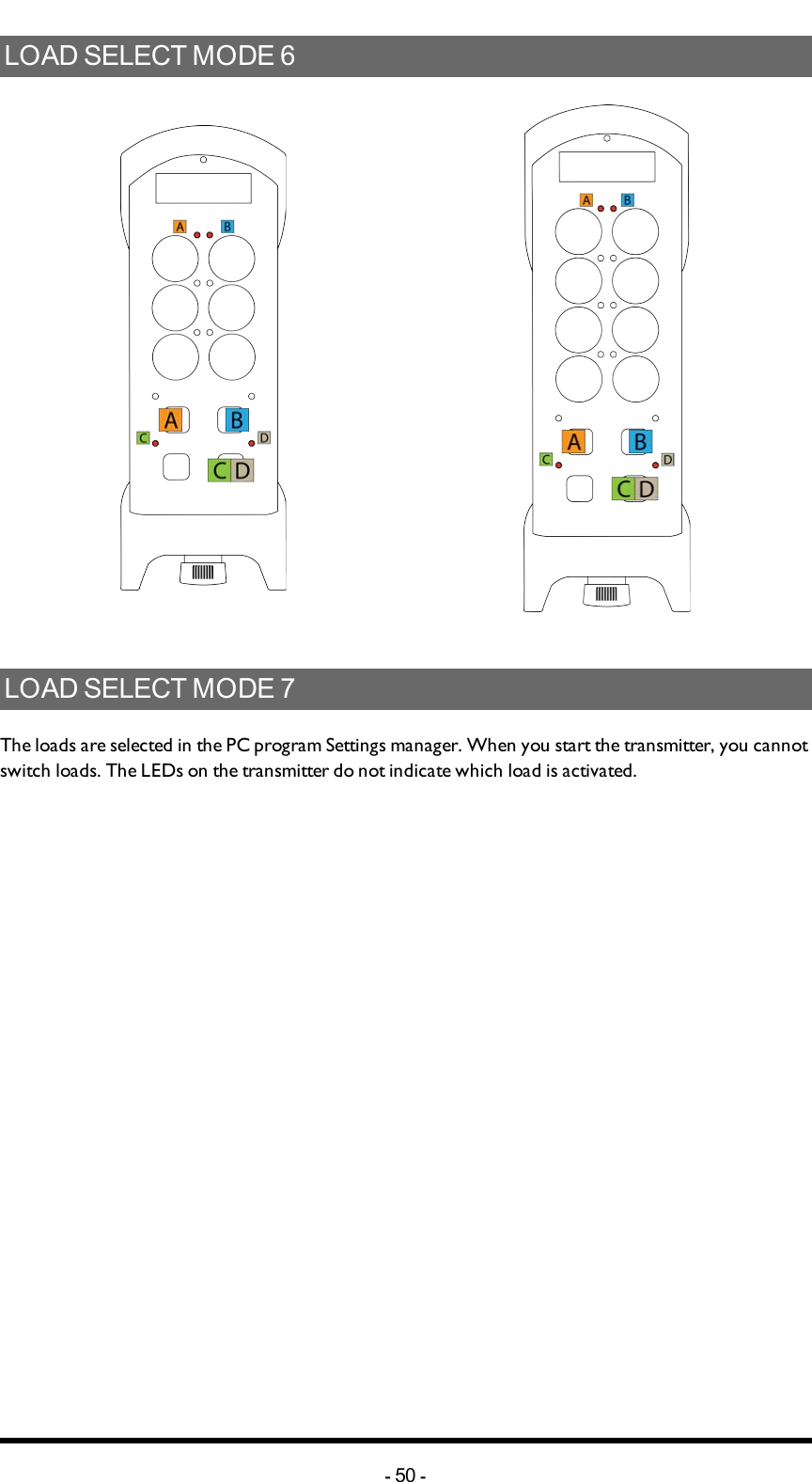
![Chapter 6: LOAD SELECT MODESCHAPTER 6: LOAD SELECT MODESLOADSELECTMODENOTE! Before starting to perform these settings, make sure that the stop relays are deactivated!1. Make sure that the stop button is pressed.2.Twist and pull out the stop button.The top LED lights (green when the battery capacity is good, red when the battery capacity is poor).3. Press the right start button. Keep pressed.4. Press the stop button. 5. Release the right start button.The top LED flashes (green when the battery capacity is good, red when the battery capacity is poor) when in menu mode. 6. Go to [Load select].7. Select Load select mode and confirm by pressing the left start button.-46 -](https://usermanual.wiki/Tele-Radio/C1406A/User-Guide-2497728-Page-46.png)